US9466448B2 - HV relay sticking control system and method - Google Patents
HV relay sticking control system and method Download PDFInfo
- Publication number
- US9466448B2 US9466448B2 US14/223,599 US201414223599A US9466448B2 US 9466448 B2 US9466448 B2 US 9466448B2 US 201414223599 A US201414223599 A US 201414223599A US 9466448 B2 US9466448 B2 US 9466448B2
- Authority
- US
- United States
- Prior art keywords
- contactor
- high voltage
- coil power
- power cycles
- sticking control
- Prior art date
- Legal status (The legal status is an assumption and is not a legal conclusion. Google has not performed a legal analysis and makes no representation as to the accuracy of the status listed.)
- Active, expires
Links
- 238000000034 method Methods 0.000 title claims abstract description 25
- 238000001514 detection method Methods 0.000 claims abstract description 23
- 230000005540 biological transmission Effects 0.000 claims description 7
- 238000010586 diagram Methods 0.000 description 5
- 230000001351 cycling effect Effects 0.000 description 2
- 230000009849 deactivation Effects 0.000 description 1
Images


Classifications
-
- H—ELECTRICITY
- H01—ELECTRIC ELEMENTS
- H01H—ELECTRIC SWITCHES; RELAYS; SELECTORS; EMERGENCY PROTECTIVE DEVICES
- H01H47/00—Circuit arrangements not adapted to a particular application of the relay and designed to obtain desired operating characteristics or to provide energising current
- H01H47/002—Monitoring or fail-safe circuits
-
- B—PERFORMING OPERATIONS; TRANSPORTING
- B60—VEHICLES IN GENERAL
- B60L—PROPULSION OF ELECTRICALLY-PROPELLED VEHICLES; SUPPLYING ELECTRIC POWER FOR AUXILIARY EQUIPMENT OF ELECTRICALLY-PROPELLED VEHICLES; ELECTRODYNAMIC BRAKE SYSTEMS FOR VEHICLES IN GENERAL; MAGNETIC SUSPENSION OR LEVITATION FOR VEHICLES; MONITORING OPERATING VARIABLES OF ELECTRICALLY-PROPELLED VEHICLES; ELECTRIC SAFETY DEVICES FOR ELECTRICALLY-PROPELLED VEHICLES
- B60L3/00—Electric devices on electrically-propelled vehicles for safety purposes; Monitoring operating variables, e.g. speed, deceleration or energy consumption
- B60L3/0023—Detecting, eliminating, remedying or compensating for drive train abnormalities, e.g. failures within the drive train
- B60L3/0069—Detecting, eliminating, remedying or compensating for drive train abnormalities, e.g. failures within the drive train relating to the isolation, e.g. ground fault or leak current
-
- B—PERFORMING OPERATIONS; TRANSPORTING
- B60—VEHICLES IN GENERAL
- B60R—VEHICLES, VEHICLE FITTINGS, OR VEHICLE PARTS, NOT OTHERWISE PROVIDED FOR
- B60R16/00—Electric or fluid circuits specially adapted for vehicles and not otherwise provided for; Arrangement of elements of electric or fluid circuits specially adapted for vehicles and not otherwise provided for
- B60R16/02—Electric or fluid circuits specially adapted for vehicles and not otherwise provided for; Arrangement of elements of electric or fluid circuits specially adapted for vehicles and not otherwise provided for electric constitutive elements
- B60R16/03—Electric or fluid circuits specially adapted for vehicles and not otherwise provided for; Arrangement of elements of electric or fluid circuits specially adapted for vehicles and not otherwise provided for electric constitutive elements for supply of electrical power to vehicle subsystems or for
-
- G—PHYSICS
- G01—MEASURING; TESTING
- G01R—MEASURING ELECTRIC VARIABLES; MEASURING MAGNETIC VARIABLES
- G01R31/00—Arrangements for testing electric properties; Arrangements for locating electric faults; Arrangements for electrical testing characterised by what is being tested not provided for elsewhere
- G01R31/327—Testing of circuit interrupters, switches or circuit-breakers
- G01R31/3277—Testing of circuit interrupters, switches or circuit-breakers of low voltage devices, e.g. domestic or industrial devices, such as motor protections, relays, rotation switches
- G01R31/3278—Testing of circuit interrupters, switches or circuit-breakers of low voltage devices, e.g. domestic or industrial devices, such as motor protections, relays, rotation switches of relays, solenoids or reed switches
-
- H—ELECTRICITY
- H01—ELECTRIC ELEMENTS
- H01H—ELECTRIC SWITCHES; RELAYS; SELECTORS; EMERGENCY PROTECTIVE DEVICES
- H01H47/00—Circuit arrangements not adapted to a particular application of the relay and designed to obtain desired operating characteristics or to provide energising current
- H01H47/002—Monitoring or fail-safe circuits
- H01H2047/003—Detecting welded contacts and applying weld break pulses to coil
Definitions
- Illustrative embodiments of the disclosure generally relate to electric vehicles. More particularly, illustrative embodiments of the disclosure generally relate to an HV (high voltage) relay sticking control system and method which reopens HV battery contactors by cycling coil power through the contactors.
- HV high voltage
- Electric vehicles including hybrid electric vehicles may include a high voltage battery pack which may be electrically connected to a pair of contactors.
- a high voltage bus may electrically interface with the contactors, and the vehicle electrical system may electrically interface with the high voltage bus.
- the contactors When the vehicle is turned off, the contactors are opened and the battery is electrically uncoupled from the high voltage bus.
- the contactors When the vehicle is turned on, the contactors are closed and the battery is electrically coupled to the high voltage bus.
- a contact weld may occur at one or both of the contactors, causing the contactor to “stick” or remain closed. This may result in undesired flow of electrical current in the battery circuit or vehicle electrical system.
- HV high voltage
- Illustrative embodiments of the disclosure are generally directed to a high voltage relay sticking control system for a vehicle having at least one contactor, a high voltage battery pack interfacing with the contactor and a weld diagnostic detection system interfacing with the high voltage battery pack and the contactor.
- An illustrative embodiment of the high voltage relay sticking control system includes an increment counter adapted to interface with the contactor, the high voltage battery pack and the weld diagnostic detection system. The increment counter is adapted to transmit at least one set of coil power cycles through the contactor if a weld exists at the contactor.
- Illustrative embodiments of the disclosure are further generally directed to a high voltage relay sticking control method for a vehicle having at least one contactor.
- An illustrative embodiment of the method includes detecting a weld at the at least one contactor and transmitting at least one set of coil power cycles through the at least one contactor.
- FIG. 1 is a block diagram of an illustrative embodiment of an HV relay sticking control system
- FIG. 2 is a block diagram of an illustrative embodiment of an HV relay sticking control method
- FIG. 3 is a block diagram of an exemplary increment counter which is suitable for implementation of the HV relay sticking control system and method.
- the word “exemplary” or “illustrative” means “serving as an example, instance, or illustration.” Any implementation described herein as “exemplary” or “illustrative” is not necessarily to be construed as preferred or advantageous over other implementations. All of the implementations described below are exemplary implementations provided to enable users skilled in the art to practice the disclosure and are not intended to limit the scope of the claims. Moreover, the illustrative embodiments described herein are not exhaustive and embodiments or implementations other than those which are described herein and which fall within the scope of the appended claims are possible. Furthermore, there is no intention to be bound by any expressed or implied theory presented in the preceding technical field, background, brief summary or the following detailed description.
- an illustrative embodiment of a high voltage (HV) relay sticking control system is generally indicated by reference numeral 120 in FIG. 1 .
- An exemplary electric vehicle which is suitable for implementation of the HV relay sticking control system 120 is generally indicated by reference numeral 100 in FIG. 1 .
- the electric vehicle 100 may be a hybrid vehicle (HEV) such as a plug in hybrid electric vehicle (PHEV), for example and without limitation.
- HEV hybrid vehicle
- PHEV plug in hybrid electric vehicle
- FIG. 3 A block diagram of an exemplary increment counter 122 which is suitable for implementation of the HV relay sticking control system 100 is shown in FIG. 3 .
- the electric vehicle 100 may include a high voltage battery pack 102 which supplies electrical power to a vehicle electrical system 114 .
- a positive contactor 108 and a negative contactor 110 may be electrically connected to a positive terminal 104 and a negative terminal 106 , respectively, of the high voltage battery pack 102 .
- a high voltage bus 112 may be electrically connected to the positive contactor 108 and the negative contactor 110 .
- the vehicle electrical system 114 may be electrically connected to the high voltage bus 112 .
- the positive contactor 108 and the negative contactor 110 are open to prevent flow of electrical current from the high voltage battery pack 102 to the vehicle electrical system 114 through the high voltage bus 112 .
- the positive contactor 108 and the negative contactor 108 close. Accordingly, electrical current flows from the high voltage battery pack 102 to the vehicle electrical system 114 through the positive contactor 108 , the negative contactor 110 and the high voltage bus 112 , respectively, for operation of the electric vehicle 100 .
- a weld diagnostic detection system 116 may be electrically connected to the high voltage battery pack 102 , the positive contactor 108 and the negative contactor 110 .
- the weld diagnostic detection system 116 determines that a “weld” exists at the positive contactor 108 or the negative contactor 110 , meaning that the positive contactor 108 or negative contactor 110 is stuck or has failed to open upon previous deactivation of the vehicle ignition, the weld diagnostic detection system 116 detects which of the positive contactor 108 and the negative contactor 110 is stuck, such as in the conventional manner.
- a vehicle controller 118 may interface with the weld diagnostic detection system 116 and the vehicle electrical system 114 .
- the HV relay sticking control system 120 may include an increment counter 122 .
- the increment counter 122 may electrically interface with the high voltage battery pack 102 , the positive contactor 108 , the negative contactor 110 and the weld diagnostic detection system 116 . In the event that it detects a weld at the positive contactor 108 or the negative contactor 110 , the weld diagnostic detection system 116 notifies the increment counter 122 .
- the increment counter 122 may be adapted to initiate and sustain at least one set 126 ( FIG. 3 ) of multiple coil power cycles 124 in which electrical current is transmitted in cycles from the high voltage battery pack 102 through the stuck positive contactor 108 or negative contactor 110 . Therefore, the coil power cycles 124 may reopen the stuck positive contactor 108 or negative contactor 110 .
- the increment counter 122 may be adapted to notify the weld diagnostic detection system 116 after each set 126 of coil power cycles 124 is transmitted through the stuck positive contactor 108 or negative contactor 110 .
- the weld diagnostic detection system 116 may be adapted to recheck the stuck or open status of the positive contactor 108 or negative contactor 110 after each set 126 of coil power cycles 124 .
- the vehicle controller 118 may initiate ignition of the electric vehicle 100 such as via the vehicle electrical system 114 .
- the weld diagnostic detection system 116 may again notify the increment counter 122 .
- the increment counter 122 may initiate and sustain a subsequent set 126 of the coil power cycles 124 through the stuck positive contactor 108 or negative contactor 110 .
- the increment counter 122 may be adapted to count the number of sets 126 of coil power cycles 124 which are transmitted through the stuck positive contactor 108 or negative contactor 110 as responses to notifications from the weld diagnostic detection system 116 that the positive contactor 108 or negative contactor 110 remains stuck. Therefore, in the event that the weld diagnostic detection system 116 notifies the increment counter 122 that the positive contactor 108 or negative contactor 110 remains stuck after a predetermined number of sets 126 of the power cycles 124 (such as 3 sets, for example and without limitation) has been transmitted through the stuck positive contactor 108 or negative contactor 110 , the increment counter 122 may be adapted to terminate further transmission of coil power cycles 124 through the positive contactor 108 or negative contactor 110 .
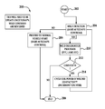
- FIG. 2 a block diagram of an illustrative embodiment of an HV relay sticking control method 200 for a vehicle is shown.
- the method 200 may start at block 202 .
- weld detection at a positive contactor or a negative contactor may be carried out.
- the vehicle may proceed to start if a weld is not detected at one of the contacts at block 204 and the method 200 may then end at block 208 .
- weld diagnostics processes may be carried out at block 210 .
- the number of sets of coil power cycles which have been transmitted through the stuck positive contactor or negative contactor may be counted.
- a predetermined number such as 0-3, for example and without limitation
- a first or subsequent set of coil power cycles may be transmitted through the stuck positive contactor or negative contactor in an attempt to open the contactor at block 214 .
- Weld detection may then again be carried out at block 204 .
- further transmission of coil power cycles may be terminated and the method may end at block 208 .
Landscapes
- Engineering & Computer Science (AREA)
- Mechanical Engineering (AREA)
- Physics & Mathematics (AREA)
- General Physics & Mathematics (AREA)
- Life Sciences & Earth Sciences (AREA)
- Sustainable Development (AREA)
- Sustainable Energy (AREA)
- Power Engineering (AREA)
- Transportation (AREA)
- Electric Propulsion And Braking For Vehicles (AREA)
Abstract
Description
Claims (20)
Priority Applications (3)
| Application Number | Priority Date | Filing Date | Title |
|---|---|---|---|
| US14/223,599 US9466448B2 (en) | 2014-03-24 | 2014-03-24 | HV relay sticking control system and method |
| DE102015104019.0A DE102015104019A1 (en) | 2014-03-24 | 2015-03-18 | HV relay bonding control system and method |
| CN201510128972.3A CN104960434B (en) | 2014-03-24 | 2015-03-24 | HV relay sticking control system and method |
Applications Claiming Priority (1)
| Application Number | Priority Date | Filing Date | Title |
|---|---|---|---|
| US14/223,599 US9466448B2 (en) | 2014-03-24 | 2014-03-24 | HV relay sticking control system and method |
Publications (2)
| Publication Number | Publication Date |
|---|---|
| US20150270081A1 US20150270081A1 (en) | 2015-09-24 |
| US9466448B2 true US9466448B2 (en) | 2016-10-11 |
Family
ID=54053789
Family Applications (1)
| Application Number | Title | Priority Date | Filing Date |
|---|---|---|---|
| US14/223,599 Active 2035-04-29 US9466448B2 (en) | 2014-03-24 | 2014-03-24 | HV relay sticking control system and method |
Country Status (3)
| Country | Link |
|---|---|
| US (1) | US9466448B2 (en) |
| CN (1) | CN104960434B (en) |
| DE (1) | DE102015104019A1 (en) |
Families Citing this family (12)
| Publication number | Priority date | Publication date | Assignee | Title |
|---|---|---|---|---|
| EP2993679B1 (en) * | 2014-09-03 | 2019-08-14 | Electrolux Appliances Aktiebolag | Apparatus-, method-, appliance and computer program product for operating a relay |
| KR101679985B1 (en) * | 2015-10-16 | 2016-12-06 | 현대자동차주식회사 | Method for detecting fusion of relay |
| KR20170052095A (en) * | 2015-11-03 | 2017-05-12 | 현대자동차주식회사 | Battery control system and method for detecting fusion of relay |
| US10090125B2 (en) * | 2016-04-27 | 2018-10-02 | GM Global Technology Operations LLC | Methods of determining the order of operating contactors in high voltage circuits |
| US10298300B2 (en) * | 2016-07-27 | 2019-05-21 | Samsung Electronics Co., Ltd. | Linear combination codebook for CSI reporting in advanced wireless communication systems |
| CN108275000A (en) * | 2017-01-06 | 2018-07-13 | 武汉英康汇通电气有限公司 | A kind of viscous dead automatic recovery control method of electric vehicle contactor |
| CN109884525B (en) * | 2017-12-01 | 2021-08-10 | 微宏动力系统(湖州)有限公司 | Adhesion detection device and method for battery pack contactor |
| JP2022508310A (en) * | 2018-11-29 | 2022-01-19 | クラブ カー エルエルシー | Utility vehicle with vehicle control module |
| FR3092434B1 (en) * | 2019-02-04 | 2021-03-19 | Renault | Power relay diagnostic and take-off process |
| US20210097785A1 (en) * | 2019-10-01 | 2021-04-01 | Ford Global Technologies, Llc | System and method for contactor status check for electrified vehicle |
| KR20210152637A (en) * | 2020-06-08 | 2021-12-16 | 주식회사 엘지에너지솔루션 | Relay diagnosis apparatus, relay diagnosis method, battery system, and electric vehicle |
| KR20220012044A (en) * | 2020-07-22 | 2022-02-03 | 주식회사 엘지에너지솔루션 | Battery apparatus, battery management system, and method of diagonsing supply voltage of contactor |
Citations (11)
| Publication number | Priority date | Publication date | Assignee | Title |
|---|---|---|---|---|
| JP2000134707A (en) | 1998-10-26 | 2000-05-12 | Toyota Motor Corp | Power supply controller |
| US6828798B2 (en) | 2002-01-10 | 2004-12-07 | Panasonic Ev Energy Co., Ltd. | Method for inspecting relay contacts for contact weld in battery power source device |
| US7242196B2 (en) | 2004-09-28 | 2007-07-10 | Panasonic Ev Energy Co., Ltd. | Power supply controller apparatus for detecting welding of contactors |
| US20070221627A1 (en) * | 2006-03-24 | 2007-09-27 | Masaki Yugou | Electric power source for motor vehicle |
| US7368829B2 (en) | 2003-03-31 | 2008-05-06 | Nec Corporation | Method and apparatus for detecting welding of a relay contact |
| US7964985B2 (en) | 2006-04-24 | 2011-06-21 | Toyota Jidosha Kabushiki Kaisha | Power supply control device and method of detecting abnormality of relay |
| US20120105065A1 (en) * | 2010-10-29 | 2012-05-03 | GM Global Technology Operations LLC | Diagnosis of hev/ev battery disconnect system |
| US20130093427A1 (en) | 2011-10-17 | 2013-04-18 | Cobasys, Llc | Welded contactor checking systems and methods |
| US20130300429A1 (en) * | 2012-05-09 | 2013-11-14 | Schneider Electric USA, Inc. | Diagnostic Receptacle For Electric Vehicle Supply Equipment |
| US20140016238A1 (en) * | 2011-03-30 | 2014-01-16 | Panasonic Corporation | Relay-welding detection circuit and power supplying system |
| US20150137819A1 (en) * | 2013-10-31 | 2015-05-21 | Lear Corporation | System and Method for Monitoring Relay Contacts |
Family Cites Families (1)
| Publication number | Priority date | Publication date | Assignee | Title |
|---|---|---|---|---|
| CN202042798U (en) * | 2011-03-07 | 2011-11-16 | 武汉理工通宇新源动力有限公司 | High-voltage power distribution system for electric automobiles |
-
2014
- 2014-03-24 US US14/223,599 patent/US9466448B2/en active Active
-
2015
- 2015-03-18 DE DE102015104019.0A patent/DE102015104019A1/en active Pending
- 2015-03-24 CN CN201510128972.3A patent/CN104960434B/en active Active
Patent Citations (12)
| Publication number | Priority date | Publication date | Assignee | Title |
|---|---|---|---|---|
| JP2000134707A (en) | 1998-10-26 | 2000-05-12 | Toyota Motor Corp | Power supply controller |
| US6828798B2 (en) | 2002-01-10 | 2004-12-07 | Panasonic Ev Energy Co., Ltd. | Method for inspecting relay contacts for contact weld in battery power source device |
| US7368829B2 (en) | 2003-03-31 | 2008-05-06 | Nec Corporation | Method and apparatus for detecting welding of a relay contact |
| US7242196B2 (en) | 2004-09-28 | 2007-07-10 | Panasonic Ev Energy Co., Ltd. | Power supply controller apparatus for detecting welding of contactors |
| US20070221627A1 (en) * | 2006-03-24 | 2007-09-27 | Masaki Yugou | Electric power source for motor vehicle |
| US8085515B2 (en) | 2006-03-24 | 2011-12-27 | Sanyo Electric Co., Ltd. | Electric power source for motor vehicle |
| US7964985B2 (en) | 2006-04-24 | 2011-06-21 | Toyota Jidosha Kabushiki Kaisha | Power supply control device and method of detecting abnormality of relay |
| US20120105065A1 (en) * | 2010-10-29 | 2012-05-03 | GM Global Technology Operations LLC | Diagnosis of hev/ev battery disconnect system |
| US20140016238A1 (en) * | 2011-03-30 | 2014-01-16 | Panasonic Corporation | Relay-welding detection circuit and power supplying system |
| US20130093427A1 (en) | 2011-10-17 | 2013-04-18 | Cobasys, Llc | Welded contactor checking systems and methods |
| US20130300429A1 (en) * | 2012-05-09 | 2013-11-14 | Schneider Electric USA, Inc. | Diagnostic Receptacle For Electric Vehicle Supply Equipment |
| US20150137819A1 (en) * | 2013-10-31 | 2015-05-21 | Lear Corporation | System and Method for Monitoring Relay Contacts |
Also Published As
| Publication number | Publication date |
|---|---|
| US20150270081A1 (en) | 2015-09-24 |
| CN104960434A (en) | 2015-10-07 |
| DE102015104019A1 (en) | 2015-09-24 |
| CN104960434B (en) | 2019-02-22 |
Similar Documents
| Publication | Publication Date | Title |
|---|---|---|
| US9466448B2 (en) | HV relay sticking control system and method | |
| US10814737B2 (en) | Off-board charger for high-voltage battery charging | |
| KR102329913B1 (en) | Battery management system for monitoring and regulating the operation of a battery and battery system having such a battery management system | |
| US10144298B2 (en) | Power supply device of vehicle | |
| CN101526578B (en) | Method and device for detecting the high-voltage faults of vehicles | |
| CN104678296B (en) | System and method for control relay contact | |
| US9821669B2 (en) | Electric vehicular connector and vehicular power supply device | |
| US9481324B2 (en) | Vehicle battery charger | |
| CN111806236A (en) | System and method for charging contact weld inspection | |
| WO2018201764A1 (en) | Electric vehicle direct current charging control guiding auxiliary circuit and system and control method | |
| JP6510050B2 (en) | Contactor control system | |
| CN106842005B (en) | Relay fault judgment method for high-voltage system of electric automobile | |
| CN106030951A (en) | Battery system and method for operating such a battery system | |
| WO2013085007A1 (en) | Charging device of electric vehicle | |
| WO2017076063A1 (en) | Charging control system and method for electric vehicle, and electric vehicle | |
| CN105034841A (en) | Strong electricity charging and discharging control method of hybrid electric vehicle and apparatus thereof | |
| CN104192018B (en) | Battery management system and method for vehicle and vehicle | |
| CN204279115U (en) | The protection system of electronlmobil medium power battery and electronlmobil | |
| JP2017093008A (en) | Contactor failure determination device and contactor failure determination method | |
| JP2017099125A (en) | Battery system, battery monitoring system of secondary battery, and monitoring method of secondary battery | |
| WO2018191829A1 (en) | Power disconnect system for transportation means having power supply system | |
| JP6642338B2 (en) | vehicle | |
| CN105939887A (en) | Charging and discharging system for an electric vehicle | |
| CN103580245A (en) | Battery management system, motor vehicle and battery system | |
| CN109030985B (en) | One-vehicle multi-gun position detection method for direct-current charging pile |
Legal Events
| Date | Code | Title | Description |
|---|---|---|---|
| AS | Assignment |
Owner name: FORD GLOBAL TECHNOLOGIES, LLC, MICHIGAN Free format text: ASSIGNMENT OF ASSIGNORS INTEREST;ASSIGNOR:HARTL, DEREK;REEL/FRAME:032513/0530 Effective date: 20130923 |
|
| STCF | Information on status: patent grant |
Free format text: PATENTED CASE |
|
| MAFP | Maintenance fee payment |
Free format text: PAYMENT OF MAINTENANCE FEE, 4TH YEAR, LARGE ENTITY (ORIGINAL EVENT CODE: M1551); ENTITY STATUS OF PATENT OWNER: LARGE ENTITY Year of fee payment: 4 |
|
| MAFP | Maintenance fee payment |
Free format text: PAYMENT OF MAINTENANCE FEE, 8TH YEAR, LARGE ENTITY (ORIGINAL EVENT CODE: M1552); ENTITY STATUS OF PATENT OWNER: LARGE ENTITY Year of fee payment: 8 |