US946292A - Window-operating mechanism. - Google Patents
Window-operating mechanism. Download PDFInfo
- Publication number
- US946292A US946292A US40856307A US1907408563A US946292A US 946292 A US946292 A US 946292A US 40856307 A US40856307 A US 40856307A US 1907408563 A US1907408563 A US 1907408563A US 946292 A US946292 A US 946292A
- Authority
- US
- United States
- Prior art keywords
- sash
- window
- teeth
- racks
- rods
- Prior art date
- Legal status (The legal status is an assumption and is not a legal conclusion. Google has not performed a legal analysis and makes no representation as to the accuracy of the status listed.)
- Expired - Lifetime
Links
- 239000002184 metal Substances 0.000 description 3
- 230000004048 modification Effects 0.000 description 2
- 238000012986 modification Methods 0.000 description 2
- 229910000831 Steel Inorganic materials 0.000 description 1
- 239000000463 material Substances 0.000 description 1
- 239000010959 steel Substances 0.000 description 1
Images
Classifications
-
- E—FIXED CONSTRUCTIONS
- E05—LOCKS; KEYS; WINDOW OR DOOR FITTINGS; SAFES
- E05D—HINGES OR SUSPENSION DEVICES FOR DOORS, WINDOWS OR WINGS
- E05D13/00—Accessories for sliding or lifting wings, e.g. pulleys, safety catches
Definitions
- the present invention relates to certain improvements in window sash operating devices, and has specially in view the production of new and useful mechanism which will positively lock the sash in an open or closed position, and at the same time permit of such manipulation whereby the sash may be allowed to automatically rise, or to be manually lowered.
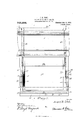
- Figure 1 is a front elevation, partly broken away, of a window frame and sash equipped with the improvements claimed herein.
- Fig. 2 is a vertical sectional view showing the sash in a locked lowered position, and also showing the connection between the sash and a raising weight and an intermediate pulley.
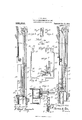
- Fig. 3 is a view similar to Fig. 2 on the line 33 of Fig. 1 but showing the sash having a connection with a spring-actuated raising roller, and also showing a modified form of operating rod and spring for the sash controlling mechanism.
- Fig. t is a detail view of the sash controlling arms.
- Fig. 5 is a horizontal sectional view taken on the line 55 of Fig. 1.
- Fig. 5 is a horizontal sectional view taken on the line 55 of Fig. 1.
- FIG. 6 is a detail view of the sash racks and one of the controlling arms showing their relative arrangement.
- Fig. 7 is a vertical sectional view of a window frame, showing a further modification of the invention.
- Fig. 8 is a detail view of the locking teeth at one end of each trip rod.
- Figs. 9 and 10 are detail sectional views respectively on the lines 99 and 1010 of Fig. 6, showing more clearly the form and relation of the teeth on the separate racks of each pair of racks.
- Fig. 11 is a detail view of the form of the flat spring shown in Figs. 3 and 7 Similar reference characters designate corresponding parts.
- 10 designates the hollow vertical side casings of a car window frame, 11 the top, and 12 the bottom or sill.
- the side casings of the frame are formed of sheet steel bent into a substantially U-shape to provide the oppositely located, outwardly extending fastening flanges 15 16, by means of which said side casings may be riveted or otherwise fastened to the wall of the car.
- the outer surface of each side casing is provided with a sheet metal facing angularly shaped to form an open sashguiding channel 17, a closed housing 18 for the sash-controlling mechanism, and an open guiding channel 19 for a window shade. (See Fig. 5).
- the sill of the window frame is also formed of sheet metal, and consists of an upper facing sheet 20, the front edge of which is bent down to form a verticalwall 21 having formed therein a guide opening 22.
- a bottom sheet 23, below the sheet 20 forms a housing for the operating end of the sash controlling mechanism, as will be presently explained.
- the upper part of the window sash frame is also formed of sheet metal and accommodates therein a pulley 24 over which a sash cord or chain 25 passes.
- This cord or chain extends down through the sash-guiding channels 17 and has its end fastened to the window sash 26.
- the other portion of said cord or chain passes down into the channel formed by the U-shaped side members and is fastened to a sash weight 25*.
- the sash weight boxes are lined with suitable sound-deadening material 25*, such as felt or the like.
- the sash 26 has the two side members 27--27 of its frame reduced in thickness at the edge 28 which is guided by the channel 17 and in each of said reduced portions two spaced-apart racks 2829 are secured the teeth of one rack being reversely disposed to the teeth of the other rack.
- each housing 18 is arranged a trip rod 32.
- the opposite rods 32 are connected at their lower ends by a transverse connecting member 32 having a pendent plate 33 from which projects a headed push pin 34, which is guided by the guide-opening 22 in the sill wall 21, through which said push pin extends.
- a spiral s ring 35 is interposed between the said bufl r plate 33 and a fixed abutment, the tension of which spring is sufficient to normally retain said plate 33 with its attached push pin, in an outwardly projected position.
- the upper ends of the rods 32 terminate in the offset bifurcated ends 37 provided with the ratchet teeth 3839, which lie in different planes to cor respond with the reverse arrangement of the teeth of the racks 2S and 29.
- a modified structure of the invention has been shown, the same consisting in connecting the sash cord or chain 25 to a spring actuated roller 2%.
- Said spring actuated roller may be of any of the well known types of automatically acting rollers, in which a spring is used that is constantly exerting a pressure upon the roller to cause itto revolve and wind upon its surface the sash cord or chain, and there by raise the window.
- a modified arrangement of operating mechanism for the trip rods 32 in which the plate 33 is dispensed with.
- the push pin 34 in this modified form of the invention connects directly with the connecting member 32 for the trip rods 32, and between said members and the wall of the sill casing a flat spring 35 is interposed, the tension of which is normally exerted to retain the trip rods in locking position.
- Fig. 7 of the drawings a further modification of the invention has been shown.
- the push rod et is arranged to have a vertical movement through the sill and is connected to the connecting member 32 for the trip rods 32 through the medium of a bell crank lever 35.
- the same form of spring 35 is used in this form of the invention as that described in Fig. 3.
- a sash carrying spaced-apart side racks the teeth of which are reversely disposed, means connected with said sash and tending to automatically raise the same, and a locking mechanism carrying forked rods the ends of which are provided with teeth corresponding to the teeth of the said side racks and adapted to engage therewith to prevent both the raising and lowering of said sash.
- a sash operating mechanism a sash the side edges of which are reduced, a pair of racks secured in each of said reduced portions of the sash, the teeth of each pair of racks being oppositely arranged, means for automatically raising said sash, and a locking mechanism comprising a spring-restrained member carrying a push pin and being provided with pivoted rods having bifurcated ends carrying teeth corresponding with the teeth of the racks and adapted to be engaged therewith to prevent raising or lowering of the sash.
Landscapes
- Engineering & Computer Science (AREA)
- Mechanical Engineering (AREA)
- Wing Frames And Configurations (AREA)
Description
J. E. ULSH. WINDOW OPERATING MECHANISM.
Patented Jan. 11,1910.
I APPLICATION FILED DEG. 30,1907. 946,292.
2 SHEETS-SHEET 1.
/2 JZ E yZ. v
ANDREW, uv GRAHAM on. FHDTD-LIYNDGR-IPHERS, WASHINGTON. DV 1:.
J. E. ULsHL I WINDOW OPERATING MECHANISM. v
APPLICATION FILED D-EO. 30,1907.
Patented Jan. 1 1, 1910,
witn eases JOSEPH E. ULSH, QF ALTOONA, PENNSYLVANIA.
WINDOW-OPERATIN G MECHANISM.
Specification of Letters Patent.
Patented Jan. 11, 1910.
Application filed December 30, 1907. Serial No. 408,563.
To all whom it may concern:
Be it known that I, JOSEPH E. ULsH, a citizen of the United States, residing at Altoona, in the county of Blair and State of Pennsylvania, have invented certain new and useful Improvements in Window-Operating Mechanism, of which the following is a specification.
The present invention relates to certain improvements in window sash operating devices, and has specially in view the production of new and useful mechanism which will positively lock the sash in an open or closed position, and at the same time permit of such manipulation whereby the sash may be allowed to automatically rise, or to be manually lowered.
In the drawings :Figure 1 is a front elevation, partly broken away, of a window frame and sash equipped with the improvements claimed herein. Fig. 2 is a vertical sectional view showing the sash in a locked lowered position, and also showing the connection between the sash and a raising weight and an intermediate pulley. Fig. 3 is a view similar to Fig. 2 on the line 33 of Fig. 1 but showing the sash having a connection with a spring-actuated raising roller, and also showing a modified form of operating rod and spring for the sash controlling mechanism. Fig. t is a detail view of the sash controlling arms. Fig. 5 is a horizontal sectional view taken on the line 55 of Fig. 1. Fig. 6 is a detail view of the sash racks and one of the controlling arms showing their relative arrangement. Fig. 7 is a vertical sectional view of a window frame, showing a further modification of the invention. Fig. 8 is a detail view of the locking teeth at one end of each trip rod. Figs. 9 and 10 are detail sectional views respectively on the lines 99 and 1010 of Fig. 6, showing more clearly the form and relation of the teeth on the separate racks of each pair of racks. Fig. 11 is a detail view of the form of the flat spring shown in Figs. 3 and 7 Similar reference characters designate corresponding parts.
In the accompanying drawings, the invention has been shown applied to car windows, although it is not intended that it should be restricted to such use.-
Referring to said drawings, 10 designates the hollow vertical side casings of a car window frame, 11 the top, and 12 the bottom or sill. The side casings of the frame are formed of sheet steel bent into a substantially U-shape to provide the oppositely located, outwardly extending fastening flanges 15 16, by means of which said side casings may be riveted or otherwise fastened to the wall of the car. The outer surface of each side casing is provided with a sheet metal facing angularly shaped to form an open sashguiding channel 17, a closed housing 18 for the sash-controlling mechanism, and an open guiding channel 19 for a window shade. (See Fig. 5). The sill of the window frame is also formed of sheet metal, and consists of an upper facing sheet 20, the front edge of which is bent down to form a verticalwall 21 having formed therein a guide opening 22. A bottom sheet 23, below the sheet 20 forms a housing for the operating end of the sash controlling mechanism, as will be presently explained. As shown in Fig. 2, the upper part of the window sash frame is also formed of sheet metal and accommodates therein a pulley 24 over which a sash cord or chain 25 passes. This cord or chain extends down through the sash-guiding channels 17 and has its end fastened to the window sash 26. The other portion of said cord or chain passes down into the channel formed by the U-shaped side members and is fastened to a sash weight 25*. The sash weight boxes are lined with suitable sound-deadening material 25*, such as felt or the like.
The sash 26 has the two side members 27--27 of its frame reduced in thickness at the edge 28 which is guided by the channel 17 and in each of said reduced portions two spaced-apart racks 2829 are secured the teeth of one rack being reversely disposed to the teeth of the other rack.
Within each housing 18 is arranged a trip rod 32. The opposite rods 32 are connected at their lower ends by a transverse connecting member 32 having a pendent plate 33 from which projects a headed push pin 34, which is guided by the guide-opening 22 in the sill wall 21, through which said push pin extends. A spiral s ring 35 is interposed between the said bufl r plate 33 and a fixed abutment, the tension of which spring is sufficient to normally retain said plate 33 with its attached push pin, in an outwardly projected position. The upper ends of the rods 32 terminate in the offset bifurcated ends 37 provided with the ratchet teeth 3839, which lie in different planes to cor respond with the reverse arrangement of the teeth of the racks 2S and 29. At an intermediate point between the ends 37 of said rods 32 and their junction with the member 3%, they are pivoted to the frame sides, as at 40. The spring 35 normally holds the teeth 38 and 39 engaged with the teeth of the racks carried by the window sash, thereby retaining the sash locked against movement. To release said rods 32 from the sash racks, the push pin is pressed in, moving the toothed ends of the rods out of engagement with said sash racks, whereupon the sash weight will raise the window automatically. But, as the pivotal movement allowed such rods 32 is not sufficient to entirely remove their toothed ends out of the path of movement of the sash racks, the result is that said teeth slip along the outer edges thereof, thereby exerting a slight frictional restraint against the movement of the sash, but not sutlicient to prevent such movement. And itwill also be understood that by means of the reverse arrangement of the teeth of the racks and the corresponding arrangement of the teeth 3839, the sash when partly raised is securely locked against movement in either direction.
In Fig. 3 of the drawings a modified structure of the invention has been shown, the same consisting in connecting the sash cord or chain 25 to a spring actuated roller 2%. Said spring actuated roller may be of any of the well known types of automatically acting rollers, in which a spring is used that is constantly exerting a pressure upon the roller to cause itto revolve and wind upon its surface the sash cord or chain, and there by raise the window. In this form of the invention there has also been shown a modified arrangement of operating mechanism for the trip rods 32 in which the plate 33 is dispensed with. The push pin 34 in this modified form of the invention connects directly with the connecting member 32 for the trip rods 32, and between said members and the wall of the sill casing a flat spring 35 is interposed, the tension of which is normally exerted to retain the trip rods in locking position.
In Fig. 7 of the drawings a further modification of the invention has been shown. In this form of the invention, the push rod et is arranged to have a vertical movement through the sill and is connected to the connecting member 32 for the trip rods 32 through the medium of a bell crank lever 35. The same form of spring 35 is used in this form of the invention as that described in Fig. 3.
I claim:
1. In a sash operating mechanism, a sash carrying spaced-apart side racks the teeth of which are reversely disposed, means connected with said sash and tending to automatically raise the same, and a locking mechanism carrying forked rods the ends of which are provided with teeth corresponding to the teeth of the said side racks and adapted to engage therewith to prevent both the raising and lowering of said sash.
2. In a sash operating mechanism, a sash the side edges of which are reduced, a pair of racks secured in each of said reduced portions of the sash, the teeth of each pair of racks being oppositely arranged, means for automatically raising said sash, and a locking mechanism comprising a spring-restrained member carrying a push pin and being provided with pivoted rods having bifurcated ends carrying teeth corresponding with the teeth of the racks and adapted to be engaged therewith to prevent raising or lowering of the sash.
In testimony whereof I hereunto atlix my signature in the presence of two witnesses.
JOSEPH E. ULSH.
lVitnesses NORMAN E. GEE, D. LLOYD GLAYCOMB.
Priority Applications (1)
| Application Number | Priority Date | Filing Date | Title |
|---|---|---|---|
| US40856307A US946292A (en) | 1907-12-30 | 1907-12-30 | Window-operating mechanism. |
Applications Claiming Priority (1)
| Application Number | Priority Date | Filing Date | Title |
|---|---|---|---|
| US40856307A US946292A (en) | 1907-12-30 | 1907-12-30 | Window-operating mechanism. |
Publications (1)
| Publication Number | Publication Date |
|---|---|
| US946292A true US946292A (en) | 1910-01-11 |
Family
ID=3014713
Family Applications (1)
| Application Number | Title | Priority Date | Filing Date |
|---|---|---|---|
| US40856307A Expired - Lifetime US946292A (en) | 1907-12-30 | 1907-12-30 | Window-operating mechanism. |
Country Status (1)
| Country | Link |
|---|---|
| US (1) | US946292A (en) |
-
1907
- 1907-12-30 US US40856307A patent/US946292A/en not_active Expired - Lifetime
Similar Documents
| Publication | Publication Date | Title |
|---|---|---|
| US946292A (en) | Window-operating mechanism. | |
| US870238A (en) | Lock mechanism for doors. | |
| US1056014A (en) | Releasing door-hanger. | |
| US1570654A (en) | Lock mechanism for slidable windows | |
| US433256A (en) | Car-door | |
| US421563A (en) | Window | |
| US714362A (en) | Roller-screen for car-windows. | |
| US995889A (en) | Device for operating vestibule doors and traps. | |
| US614713A (en) | Automatic weather-strip for doors | |
| US894903A (en) | Weather-strip. | |
| US153232A (en) | Improvement in sash-holders | |
| US1157760A (en) | Self-locking window-operating device. | |
| US1216436A (en) | Car-door. | |
| US946482A (en) | Automatic or self-adjustable weather-strip. | |
| US855933A (en) | Car-window. | |
| US803038A (en) | Automatic device for closing fireproof shutters. | |
| US1000352A (en) | Window-screen. | |
| US599161A (en) | Fourth to richard mcgahey | |
| US537741A (en) | Door or window protector | |
| US1129537A (en) | Gate for elevator-shafts. | |
| US1282979A (en) | Window. | |
| US500759A (en) | Henry chandler fuller | |
| US754575A (en) | Window-sash. | |
| US913610A (en) | Fire-escape door. | |
| US1006264A (en) | Sash-balance. |