US9448357B2 - Illuminated facade arrangement - Google Patents
Illuminated facade arrangement Download PDFInfo
- Publication number
- US9448357B2 US9448357B2 US14/110,909 US201214110909A US9448357B2 US 9448357 B2 US9448357 B2 US 9448357B2 US 201214110909 A US201214110909 A US 201214110909A US 9448357 B2 US9448357 B2 US 9448357B2
- Authority
- US
- United States
- Prior art keywords
- pane
- led
- arrangement according
- facade
- facade arrangement
- Prior art date
- Legal status (The legal status is an assumption and is not a legal conclusion. Google has not performed a legal analysis and makes no representation as to the accuracy of the status listed.)
- Expired - Fee Related, expires
Links
Images


Classifications
-
- G—PHYSICS
- G02—OPTICS
- G02B—OPTICAL ELEMENTS, SYSTEMS OR APPARATUS
- G02B6/00—Light guides; Structural details of arrangements comprising light guides and other optical elements, e.g. couplings
- G02B6/0001—Light guides; Structural details of arrangements comprising light guides and other optical elements, e.g. couplings specially adapted for lighting devices or systems
- G02B6/0011—Light guides; Structural details of arrangements comprising light guides and other optical elements, e.g. couplings specially adapted for lighting devices or systems the light guides being planar or of plate-like form
- G02B6/0081—Mechanical or electrical aspects of the light guide and light source in the lighting device peculiar to the adaptation to planar light guides, e.g. concerning packaging
- G02B6/0095—Light guides as housings, housing portions, shelves, doors, tiles, windows, or the like
-
- F—MECHANICAL ENGINEERING; LIGHTING; HEATING; WEAPONS; BLASTING
- F21—LIGHTING
- F21V—FUNCTIONAL FEATURES OR DETAILS OF LIGHTING DEVICES OR SYSTEMS THEREOF; STRUCTURAL COMBINATIONS OF LIGHTING DEVICES WITH OTHER ARTICLES, NOT OTHERWISE PROVIDED FOR
- F21V7/00—Reflectors for light sources
-
- B—PERFORMING OPERATIONS; TRANSPORTING
- B32—LAYERED PRODUCTS
- B32B—LAYERED PRODUCTS, i.e. PRODUCTS BUILT-UP OF STRATA OF FLAT OR NON-FLAT, e.g. CELLULAR OR HONEYCOMB, FORM
- B32B17/00—Layered products essentially comprising sheet glass, or glass, slag, or like fibres
- B32B17/06—Layered products essentially comprising sheet glass, or glass, slag, or like fibres comprising glass as the main or only constituent of a layer, next to another layer of a specific material
- B32B17/10—Layered products essentially comprising sheet glass, or glass, slag, or like fibres comprising glass as the main or only constituent of a layer, next to another layer of a specific material of synthetic resin
- B32B17/10005—Layered products essentially comprising sheet glass, or glass, slag, or like fibres comprising glass as the main or only constituent of a layer, next to another layer of a specific material of synthetic resin laminated safety glass or glazing
- B32B17/10009—Layered products essentially comprising sheet glass, or glass, slag, or like fibres comprising glass as the main or only constituent of a layer, next to another layer of a specific material of synthetic resin laminated safety glass or glazing characterized by the number, the constitution or treatment of glass sheets
- B32B17/10036—Layered products essentially comprising sheet glass, or glass, slag, or like fibres comprising glass as the main or only constituent of a layer, next to another layer of a specific material of synthetic resin laminated safety glass or glazing characterized by the number, the constitution or treatment of glass sheets comprising two outer glass sheets
- B32B17/10045—Layered products essentially comprising sheet glass, or glass, slag, or like fibres comprising glass as the main or only constituent of a layer, next to another layer of a specific material of synthetic resin laminated safety glass or glazing characterized by the number, the constitution or treatment of glass sheets comprising two outer glass sheets with at least one intermediate layer consisting of a glass sheet
- B32B17/10055—Layered products essentially comprising sheet glass, or glass, slag, or like fibres comprising glass as the main or only constituent of a layer, next to another layer of a specific material of synthetic resin laminated safety glass or glazing characterized by the number, the constitution or treatment of glass sheets comprising two outer glass sheets with at least one intermediate layer consisting of a glass sheet with at least one intermediate air space
-
- B—PERFORMING OPERATIONS; TRANSPORTING
- B32—LAYERED PRODUCTS
- B32B—LAYERED PRODUCTS, i.e. PRODUCTS BUILT-UP OF STRATA OF FLAT OR NON-FLAT, e.g. CELLULAR OR HONEYCOMB, FORM
- B32B17/00—Layered products essentially comprising sheet glass, or glass, slag, or like fibres
- B32B17/06—Layered products essentially comprising sheet glass, or glass, slag, or like fibres comprising glass as the main or only constituent of a layer, next to another layer of a specific material
- B32B17/10—Layered products essentially comprising sheet glass, or glass, slag, or like fibres comprising glass as the main or only constituent of a layer, next to another layer of a specific material of synthetic resin
- B32B17/10005—Layered products essentially comprising sheet glass, or glass, slag, or like fibres comprising glass as the main or only constituent of a layer, next to another layer of a specific material of synthetic resin laminated safety glass or glazing
- B32B17/10165—Functional features of the laminated safety glass or glazing
- B32B17/10174—Coatings of a metallic or dielectric material on a constituent layer of glass or polymer
-
- F—MECHANICAL ENGINEERING; LIGHTING; HEATING; WEAPONS; BLASTING
- F21—LIGHTING
- F21V—FUNCTIONAL FEATURES OR DETAILS OF LIGHTING DEVICES OR SYSTEMS THEREOF; STRUCTURAL COMBINATIONS OF LIGHTING DEVICES WITH OTHER ARTICLES, NOT OTHERWISE PROVIDED FOR
- F21V17/00—Fastening of component parts of lighting devices, e.g. shades, globes, refractors, reflectors, filters, screens, grids or protective cages
-
- F—MECHANICAL ENGINEERING; LIGHTING; HEATING; WEAPONS; BLASTING
- F21—LIGHTING
- F21V—FUNCTIONAL FEATURES OR DETAILS OF LIGHTING DEVICES OR SYSTEMS THEREOF; STRUCTURAL COMBINATIONS OF LIGHTING DEVICES WITH OTHER ARTICLES, NOT OTHERWISE PROVIDED FOR
- F21V33/00—Structural combinations of lighting devices with other articles, not otherwise provided for
- F21V33/006—General building constructions or finishing work for buildings, e.g. roofs, gutters, stairs or floors; Garden equipment; Sunshades or parasols
-
- F—MECHANICAL ENGINEERING; LIGHTING; HEATING; WEAPONS; BLASTING
- F21—LIGHTING
- F21W—INDEXING SCHEME ASSOCIATED WITH SUBCLASSES F21K, F21L, F21S and F21V, RELATING TO USES OR APPLICATIONS OF LIGHTING DEVICES OR SYSTEMS
- F21W2131/00—Use or application of lighting devices or systems not provided for in codes F21W2102/00-F21W2121/00
- F21W2131/40—Lighting for industrial, commercial, recreational or military use
- F21W2131/405—Lighting for industrial, commercial, recreational or military use for shop-windows or displays
-
- F21Y2103/003—
-
- F—MECHANICAL ENGINEERING; LIGHTING; HEATING; WEAPONS; BLASTING
- F21—LIGHTING
- F21Y—INDEXING SCHEME ASSOCIATED WITH SUBCLASSES F21K, F21L, F21S and F21V, RELATING TO THE FORM OR THE KIND OF THE LIGHT SOURCES OR OF THE COLOUR OF THE LIGHT EMITTED
- F21Y2103/00—Elongate light sources, e.g. fluorescent tubes
- F21Y2103/10—Elongate light sources, e.g. fluorescent tubes comprising a linear array of point-like light-generating elements
-
- F—MECHANICAL ENGINEERING; LIGHTING; HEATING; WEAPONS; BLASTING
- F21—LIGHTING
- F21Y—INDEXING SCHEME ASSOCIATED WITH SUBCLASSES F21K, F21L, F21S and F21V, RELATING TO THE FORM OR THE KIND OF THE LIGHT SOURCES OR OF THE COLOUR OF THE LIGHT EMITTED
- F21Y2115/00—Light-generating elements of semiconductor light sources
- F21Y2115/10—Light-emitting diodes [LED]
-
- G—PHYSICS
- G02—OPTICS
- G02B—OPTICAL ELEMENTS, SYSTEMS OR APPARATUS
- G02B6/00—Light guides; Structural details of arrangements comprising light guides and other optical elements, e.g. couplings
- G02B6/0001—Light guides; Structural details of arrangements comprising light guides and other optical elements, e.g. couplings specially adapted for lighting devices or systems
- G02B6/0011—Light guides; Structural details of arrangements comprising light guides and other optical elements, e.g. couplings specially adapted for lighting devices or systems the light guides being planar or of plate-like form
- G02B6/0066—Light guides; Structural details of arrangements comprising light guides and other optical elements, e.g. couplings specially adapted for lighting devices or systems the light guides being planar or of plate-like form characterised by the light source being coupled to the light guide
- G02B6/0073—Light emitting diode [LED]
-
- G—PHYSICS
- G02—OPTICS
- G02B—OPTICAL ELEMENTS, SYSTEMS OR APPARATUS
- G02B6/00—Light guides; Structural details of arrangements comprising light guides and other optical elements, e.g. couplings
- G02B6/0001—Light guides; Structural details of arrangements comprising light guides and other optical elements, e.g. couplings specially adapted for lighting devices or systems
- G02B6/0011—Light guides; Structural details of arrangements comprising light guides and other optical elements, e.g. couplings specially adapted for lighting devices or systems the light guides being planar or of plate-like form
- G02B6/0081—Mechanical or electrical aspects of the light guide and light source in the lighting device peculiar to the adaptation to planar light guides, e.g. concerning packaging
- G02B6/0083—Details of electrical connections of light sources to drivers, circuit boards, or the like
-
- Y—GENERAL TAGGING OF NEW TECHNOLOGICAL DEVELOPMENTS; GENERAL TAGGING OF CROSS-SECTIONAL TECHNOLOGIES SPANNING OVER SEVERAL SECTIONS OF THE IPC; TECHNICAL SUBJECTS COVERED BY FORMER USPC CROSS-REFERENCE ART COLLECTIONS [XRACs] AND DIGESTS
- Y10—TECHNICAL SUBJECTS COVERED BY FORMER USPC
- Y10T—TECHNICAL SUBJECTS COVERED BY FORMER US CLASSIFICATION
- Y10T29/00—Metal working
- Y10T29/49—Method of mechanical manufacture
- Y10T29/49826—Assembling or joining
Definitions
- the invention relates to an illuminated double or triple glazing, a façade constructed of the illuminated double or triple glazing, a method for producing the double or triple glazing, and use thereof.
- Illuminated window arrangements include panes and lighting means mounted directly on the edge of the panes. Reflective elements mounted on the pane surface enable the homogeneous illumination of the pane area. Thus, interior spaces and also exterior building façades can be very uniformly illuminated. Illuminated window arrangements are found in a large number of areas of application inside and outside buildings and motor vehicles.
- a very uniform, area, ambient light can be generated by an illuminated window arrangement.
- different light effects can also be realized.
- moving light effects can be generated through targeted activation and extinguishing of individual LEDs. For the observer, the light seems to spread out in waves of color. If multiple waves of color overlay each other, further effects such as a colored so-called moiré effect are produced.
- These light and color effects can also be used for advertising spaces or to generate artistic and architectonic effects.
- the pane For radiation of the light out of the pane, light reflectors mounted on the pane are necessary. For this, the pane can be printed on or provided with corresponding incisions. Since the light of the LEDs is coupled on the sides, a large proportion of the incident light is often lost. With use in double and triple glazings, the installation of the light reflectors, which not insubstantially increases the cost of the process, must be taken into account. In addition, the type of glazing quite substantially affects the amount of light radiated by the pane.
- DE 102 24 421 A1 discloses a light wall with lamps that is arranged behind a computer workstation.
- the light wall consists of a transparent glass or plastic pane, preferably illuminated by LEDs.
- the brightness and color components can be regulated by a control unit.
- the control unit can be directly connected to the PC of the computer workstation and can regulate the brightness of the workstation as a function of the brightness of the monitor.
- EP 1 379 742 B1 discloses an illuminated urban furnishing with windows in a frame structure.
- the lighting means are disposed on the front face of the window and radiate the incident light perpendicularly outward.
- EP 1 106 915 A1 discloses an illuminated urban furnishing with windows in a frame structure.
- the lighting means are disposed on the front face of the window and radiate the incident light perpendicularly outward.
- EP 1 106 915 A1 discloses an illuminated urban furnishing with windows in a frame structure.
- the lighting means are disposed on the front face of the window and radiate the incident light perpendicularly outward.
- EP 1 346 178 B1 discloses a sandwich-like panel element.
- the two panels are largely transparent to light.
- Solar cell elements are mounted in the intermediate space of the panel or on the panels.
- a light source is arranged on the front face of at least one panel and enables additional illumination.
- DE 10 2005 061 855 A1 discloses a glass element as part of a façade with a long afterglow effect.
- the long afterglow element has a long afterglow pigment in a matrix.
- DE 10 2005 036 869 A1 discloses a multilayer composite structure for covering interiors or exteriors of buildings or parts of buildings.
- the composite structure comprises at least one transparent rigid layer, a plurality of light conductive fibers, and one or a plurality of connectors for connection of the light conductive fibers to a light source.
- U.S. Pat. No. 6,185,883 B1 discloses a window with decorative elements.
- the window frame includes a triple insulating glazing with decorative elements in the middle pane.
- the object of the invention is to provide a glazing on which an LED strip can be mounted and maintained without measures to reconstruct the glazing being necessary.
- the glazing should also radiate the greatest possible amount of light from the pane surface.
- the installed electronic light sources and their feed lines must be implemented very long-lasting and robust. To that end, they should have a protection class in accordance with DIN EN 60529 of at least IP64, preferably IP67.
- a façade according to the invention, a method for producing the illuminated window arrangement, and the use of the window arrangement according to the invention emerge from other independent claims.
- the illuminated insulating glazing according to the invention comprises at least one composite glass pane and a lower (outer) pane.
- a circumferential (frame-like) connection element between the composite glass pane and the lower pane forms the basic structure of the insulating glazing.
- the connection element can, optionally, also be implemented in the form of two (connectable) connection elements.
- the panes contain materials such as glass and/or transparent polymers.
- the panes preferably have an optical transparency of >85%. In principle, various geometries of the panes are possible, for example, rectangular, trapezoidal, and rounded geometries.
- An LED housing is fastened to the side edge of the lower pane.
- the LED housing contains at least one LED, one LED printed circuit board (PCB) fastened to the LED, and one electrical connector fastened to the LED printed circuit board.
- the LEDs preferably include LEDs (light emitting diodes) and/or OLEDs (organic light emitting diodes).
- the LED printed circuit board includes commercially available PCBs and/or cards. These are made of electrically insulating materials on which electrical connections are mounted. Examples of insulating materials are nonconductive polymers such as epoxy-resin-impregnated glass fibers, Teflon, ceramic, and/or polyester film.
- the electrical connections for example, conducting wires, contain preferably copper, iron, tin, nickel, gold, silver, and/or alloys thereof.
- the LEDs are fastened to the LED printed circuit boards and make contact via the electrical connections.
- the electrical connector represents the connection to the power source.
- a control device is also arranged between the electrical connector and the power source. This control device enables targeted illumination of individual LEDs. Through the arrangement of different colored LEDs on the LED printed circuit board, colored light effects can be generated.
- the entire arrangement of the components made up of LED, LED printed circuit board, and electrical connector is situated inside sheathing. This sheathing can be implemented as a flexible or rigid housing.
- the LED housing is connected to the side edge of the lower pane via an optically transparent adhesive and/or adhesive tape.
- a reflector is preferably disposed between the connection element adjacent the LED housing and the lower pane.
- the reflector comprises bright coats of paint, for example, ceramic paint and bright polymer or metal bodies. The reflector prevents or reduces light loss in the region of the connection elements.
- the composite glass pane preferably comprises an upper pane, an adhesive layer, and a middle pane.
- the adhesive layer preferably contains PVB (polyvinyl butyral) and/or EVA (poly-ethylvinyl acetate).
- the adhesive layer optionally contains a polyester film, preferably polybutylene terephthalate (PBT), polycarbonate (PC), polyethylene terephthalate (PET), and polyethylene naphthalate (PEN), and/or mixtures and/or copolymers thereof.
- the adhesive layer can include a plurality of layers of the same or different polymers.
- the composite glass pane and/or the middle pane preferably have a thermal protection coating.
- the thermal protection coating preferably contains silver.
- the insulating glazing preferably has an optical transparency of >60%, preferably of >75%, particularly preferably of >85%.
- optical transparency describes, in the context of the invention, a mean optical transmission in the wavelength range from 400 nm to 800 nm (VIS range).
- the lower pane preferably contains luminous fields.
- the luminous fields reflect, emit, or diffuse the light coupled into the upper pane by the LEDs outward.
- the pane lights only in the region of the luminous fields.
- the entire radiating surface of the lower pane is provided with reflectors, the entire lower pane on the opposite side lights accordingly.
- the luminous fields preferably include structures for diffusion of light, particularly preferably particles, dot patterns, etched surfaces, stickers, deposits, indentations, incisions, line patterns, overprints, and/or screen prints.
- This sheathing preferably contains an optically transparent polymer, particularly preferably polyurethanes, silicones, polyisoprenes, styrene-butadiene rubber, butadiene acrylonitrile rubber, and/or polyacrylates as well as mixtures and/or copolymers thereof.
- an optically transparent polymer particularly preferably polyurethanes, silicones, polyisoprenes, styrene-butadiene rubber, butadiene acrylonitrile rubber, and/or polyacrylates as well as mixtures and/or copolymers thereof.
- the silicones preferably include RTV (room temperature vulcanizing) silicone rubber, HTV (high temperature vulcanizing) silicone rubber, peroxide vulcanizing silicone rubber, and/or addition vulcanizing silicone rubber as well as mixtures and/or copolymers thereof.
- RTV room temperature vulcanizing
- HTV high temperature vulcanizing silicone rubber
- peroxide vulcanizing silicone rubber peroxide vulcanizing silicone rubber
- addition vulcanizing silicone rubber as well as mixtures and/or copolymers thereof.
- the LED housing is preferably fastened to the side edge of the lower pane with an optically transparent adhesive and/or adhesive tape.
- the selection of the adhesive on the adhesive tape is guided by the material of the pane or of the sheathing.
- the optically transparent adhesive tape preferably contains a silicone-based adhesive on the side facing the sheathing and an acrylate-based adhesive on the side facing the pane.
- sheathing made of silicone can be fixedly connected to a pane made of glass or polyacrylic.
- the optically transparent adhesive tape is preferably activated by a corona discharge.
- the LED housing is preferably non-loadbearingly connected to the lower pane.
- non-loadbearingly means, in the context of the invention, that the LED housing is not in direct contact with the possible mounting devices of the illuminated triple glazing.
- the LED housing is preferably part of the non-loadbearing structure and thus does not itself contribute to the stability. This non-loadbearing assembly enables simple exchange and maintenance of the LED housing.
- An optically transparent adhesive and/or adhesive tape preferably contains acrylate adhesives, methyl methacrylate adhesives, cyanoacrylate adhesives, polyepoxies, silicone adhesives, and/or silane cross-linking polymer adhesives as well as mixtures and/or copolymers thereof.
- An optically transparent adhesive and/or adhesive tape preferably has an optical transparency of >80%, particularly preferably >90%.
- the LEDs preferably have a distance from the upper pane of ⁇ 1 mm, preferably ⁇ 0.5 mm.
- the LED printed circuit board preferably contains silver, copper, tin, nickel, gold, aluminum, iron, tungsten, chromium, and/or alloys thereof and/or an electrically conductive adhesive tape.
- connection elements preferably have a width of 5 mm to 20 mm and a height of 5 mm to 10 mm.
- the height is determined along the edge of the connection element pointing toward the composite pane and/or lower pane.
- the width is measured along the edge to the intermediate space between the composite glass pane and the lower pane.
- the connection elements are preferably implemented in block or cube shape.
- the connection elements preferably contain polymers and/or metals.
- the LED housing preferably has a recess for a cable.
- the recess enables the space-saving arrangement of a plurality of LED housings or LED strips in a row on a relatively long glass pane. Additionally, no additional space in the sheathing is required with the cable guided through the recess.
- Das LED housing preferably has a structural height less than 10 mm, preferably less than 8 mm. In a façade structure, this enables very compact construction.
- the invention further includes an illuminated façade arrangement, wherein two above-described illuminated triple glazings according to the invention are connected via fastening units to a façade mount.
- a cover is fastened between the individual insulating glazings to the sides of the insulating glazings turned away from the façade side.
- the supplying of power to the LED housing inside the illuminated insulating glazing according to the invention takes place via a cable from the LED housing to a (main) power feed inside the cover.
- the preferably removable cover enables simple exchanging of the LED housing.
- the invention further includes a method for producing an illuminated window arrangement.
- a first step an upper pane is connected to a middle pane via an adhesive layer in an autoclave. Subsequently or at the same time, at least one LED on a printed circuit board and an electrical connector are connected to form an LED arrangement.
- the arrangement obtained is provided with a sheathing and an LED housing is obtained. Then, in advance or at the same time, the middle pane and a lower pane are connected via a circumferential connection element.
- the connection elements are preferably further sealed with gaskets, for example, silicone-based gaskets.
- the LED housing is fastened to the side edge or to the edge of the lower pane via an optically transparent adhesive and/or adhesive tape.
- the invention further includes the use of the illuminated window arrangement as an illuminated external façade, building interior illumination, building exterior illumination, advertising medium, and/or a motor vehicle window pane.
- FIG. 1 depicts a cross-section of the illuminated triple glazing (I)
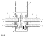
- FIG. 2 depicts a cross-section of the illuminated façade arrangement (II),
- FIG. 3 depicts another, schematic, detailed cross-section of the illuminated façade arrangement (II),
- FIG. 4 depicts a flowchart of the method according to the invention.
- FIG. 5 depicts a cross-section of a preferred embodiment of the LED housing.
- FIG. 1 depicts a cross-section of the illuminated window arrangement (I) according to the invention, consisting of a triple glazing.
- An upper pane ( 1 ) ist connected via an adhesive layer ( 2 ) to a middle pane ( 3 ) to form a composite glass pane ( 21 ).
- the middle pane ( 3 ) is fastened via a circumferential connection element ( 4 ) and a gasket ( 5 ) to a lower pane ( 6 ).
- the gasket ( 5 ) preferably contains a bright light reflecting material.
- An LED housing ( 8 ) is connected via an optically transparent adhesive ( 14 ) to the side edge of the lower pane ( 6 ).
- side edge or “edge” preferably describes, in the context of the invention, the smaller outside edge, perpendicular to the look-through side of the lower pane.
- An electrical connector ( 19 ) provides the LEDs ( 17 ) with current.
- a sheathing ( 20 ) made of transparent polyurethane or silicone forms the outer framework of the LED housing ( 8 ).
- FIG. 2 depicts a cross-section of the illuminated façade arrangement (II).
- the window arrangement (I) according to the invention is fastened via a façade mount ( 11 ) and fastening units ( 12 ) anchored thereon.
- the structure of the window arrangements (I) corresponds to the arrangement depicted in FIG. 1 .
- the LED housing ( 8 ) is provided with current via a cable ( 9 ) out of the main cable ( 10 ).
- the main cable ( 10 ) lies inside a removable cover ( 15 ) connected via an external fastening element ( 7 ).
- the LED housing ( 8 ), cable ( 9 ), and main cable ( 10 ) can be readily exchanged and maintained by removing the cover ( 15 ).
- FIG. 3 depicts an enlarged, schematic cross-section of the illuminated façade arrangement.
- the structure corresponds to that described in FIGS. 1 and 2 .
- the cover can optionally have various reversibly reclosable openings ( 16 ).
- FIG. 4 depicts a flowchart for producing the illuminated window arrangement (I) according to the invention.
- an upper pane ( 1 ) is connected via an adhesive layer ( 2 ) to a middle pane ( 3 ) in an autoclave.
- LEDs ( 17 ) are connected to an LED printed circuit board ( 18 ) and an electrical connector ( 19 ) to form an LED arrangement.
- the arrangement obtained is provided with a sheathing ( 20 ) and an LED housing ( 8 ) is obtained.
- the middle pane ( 3 ) and a lower pane ( 6 ) are connected via a circumferential connection element ( 4 ) to form an insulating glazing (I).
- the LED housing ( 8 ) is fastened to the edge of the lower pane ( 6 ) via an optically transparent adhesive and/or adhesive tape ( 14 ).
- the fastening of the LED housing ( 8 ) to the side edge or to the edge of the lower pane ( 6 ) prevents a contribution of the LED housing ( 8 ) to the load of the insulating glazing (I).
- the LED housing ( 8 ) in a façade arrangement can be exchanged, without the loadbearing elements such as, for instance, the fastening units ( 12 ) being influenced or even affected.
- the insulating glazing (I) is fastened to the fastening elements ( 12 ) of the façade mount ( 11 ).
- the electrical connecting of the cable ( 9 ) to the main cable ( 10 ) and the installation of the cover ( 15 ) take place.
- FIG. 5 depicts a cross-section of a preferred embodiment of the LED housing ( 8 ).
- the LED housing ( 8 ) has a recess ( 24 ) for the space-saving arrangement of the cable ( 9 ).
- the recess preferably has a length corresponding to 2% to 10% of the entire length of the LED housing ( 8 ).
- the recess further enables the direct arrangement of a plurality of LED housings ( 8 ) along the side edge of the lower pane ( 6 ).
- the window arrangement and façade arrangement according to the invention surprisingly and unexpectedly permit maintenance of the LEDs without the glazing having to be reconstructed.
- the arrangement according to the invention is very economical to produce and advantageous to maintain. This was unexpected and surprising for the person skilled in the art.
Abstract
-
- composite glass pane,
- at least one circumferential connection element between the composite glass pane and a lower pane, and
- LED housing fastened to a side edge of the lower pane, an LED printed circuit board fastened to the LED, an electrical connector fastened to the LED printed circuit board, and sheathing of the LED, the LED printed circuit board, and the electrical connector.
Description
- (1) upper pane
- (2) adhesive layer
- (3) middle pane
- (4) circumferential connection element (spacer)
- (5) gasket
- (6) lower pane/outer pane
- (7) external fastening element
- (8) LED housing
- (9) cable/connection cable
- (10) main cable
- (11) façade mount
- (12) fastening element
- (13) luminous fields
- (14) optically transparent adhesive and/or adhesive tape
- (15) cover
- (16) opening
- (17) LED
- (18) LED printed circuit board
- (19) electrical connector (LED)
- (20) sheathing
- (21) composite glass pane
- (22) reflector
- (23) thermal protection coating
- (24) recess
- (I, I′) window arrangement
- (II) façade arrangement
Claims (14)
Applications Claiming Priority (4)
| Application Number | Priority Date | Filing Date | Title |
|---|---|---|---|
| EP11161828 | 2011-04-11 | ||
| EP11161828 | 2011-04-11 | ||
| EP11161828.6 | 2011-04-11 | ||
| PCT/EP2012/052256 WO2012139787A1 (en) | 2011-04-11 | 2012-02-10 | Illuminated double glazing |
Publications (2)
| Publication Number | Publication Date |
|---|---|
| US20140218934A1 US20140218934A1 (en) | 2014-08-07 |
| US9448357B2 true US9448357B2 (en) | 2016-09-20 |
Family
ID=45571547
Family Applications (1)
| Application Number | Title | Priority Date | Filing Date |
|---|---|---|---|
| US14/110,909 Expired - Fee Related US9448357B2 (en) | 2011-04-11 | 2012-02-10 | Illuminated facade arrangement |
Country Status (6)
| Country | Link |
|---|---|
| US (1) | US9448357B2 (en) |
| EP (1) | EP2697057B1 (en) |
| JP (1) | JP6005131B2 (en) |
| KR (1) | KR101610453B1 (en) |
| CN (1) | CN103459143A (en) |
| WO (1) | WO2012139787A1 (en) |
Cited By (1)
| Publication number | Priority date | Publication date | Assignee | Title |
|---|---|---|---|---|
| US10247874B2 (en) * | 2017-01-30 | 2019-04-02 | Florian Eyme | Edge-lit glass wall system |
Families Citing this family (9)
| Publication number | Priority date | Publication date | Assignee | Title |
|---|---|---|---|---|
| FR2978525B1 (en) * | 2011-07-29 | 2018-05-18 | Saint-Gobain Glass France | LUMINOUS MULTIPLE FURNITURE GLAZING |
| US8974077B2 (en) | 2012-07-30 | 2015-03-10 | Ultravision Technologies, Llc | Heat sink for LED light source |
| DE102012111442A1 (en) * | 2012-11-26 | 2014-05-28 | SCHÜCO International KG | Window, door or façade element with a glass bridge with integrated light source |
| DE102013100249A1 (en) * | 2013-01-11 | 2014-07-17 | SCHÜCO International KG | Window, door or facade component for building, has profiles receiving surface element and comprising glass folding part in which glass folding elements are arranged, where glass folding elements are transparent light from light source |
| MX2015014963A (en) * | 2013-04-26 | 2016-05-09 | Doors Covers & More B V | Double-walled acrylic door for refrigerated cabinets. |
| US9195281B2 (en) | 2013-12-31 | 2015-11-24 | Ultravision Technologies, Llc | System and method for a modular multi-panel display |
| US20150309248A1 (en) * | 2014-04-24 | 2015-10-29 | Axlen, Inc. | Led-based lighting devices and systems based on light panels having transparent waveguides |
| ES2582000B1 (en) * | 2016-02-17 | 2017-05-31 | Vitrallart, S.L. | DEVICE FOR SUPPORT AND / OR REMATE OF TRANSPARENT OR TRANSLUCED PLATES, WITH INCORPORATED LIGHTING |
| DE102022104600A1 (en) | 2022-02-25 | 2023-08-31 | Webasto SE | Vehicle window and method for manufacturing a vehicle window |
Citations (23)
| Publication number | Priority date | Publication date | Assignee | Title |
|---|---|---|---|---|
| US4643944A (en) * | 1976-07-02 | 1987-02-17 | Saint-Gobain Vitrage | Glazing laminates and method of making same |
| JPH07237941A (en) | 1994-02-23 | 1995-09-12 | Nippon Sheet Glass Co Ltd | Multiple glass |
| DE29510238U1 (en) | 1995-06-23 | 1995-11-02 | Emde Thomas | window |
| DE29706568U1 (en) | 1997-04-11 | 1997-08-14 | Ohlow Stefan | Lighting device |
| DE19852593A1 (en) | 1998-11-14 | 2000-05-25 | Daimler Chrysler Ag | Arrangement for use as area light and as transparent glazing has variable transmissivity panel on one side of illuminated pane; panel is transparent when light source is switched off |
| US6185883B1 (en) | 1998-12-31 | 2001-02-13 | Noel Howard | Window with decorative accessories |
| EP1106915A1 (en) | 1999-12-09 | 2001-06-13 | Thomas Emde | Flat luminous elements system |
| WO2002052191A1 (en) | 2000-12-22 | 2002-07-04 | Thomas Emde | Window element |
| WO2002052192A1 (en) | 2000-12-22 | 2002-07-04 | Thomas Emde | Sandwich-like panel element |
| EP1379742A1 (en) | 2001-04-06 | 2004-01-14 | Thomas Emde | Public outdoor furnishings comprising an illuminated glass pane |
| WO2004007887A1 (en) * | 2002-07-12 | 2004-01-22 | Thomas Emde | Window element |
| US20040031234A1 (en) * | 2000-12-22 | 2004-02-19 | Thomas Emde | Window element |
| DE10224421A1 (en) | 2002-06-01 | 2004-04-29 | Arne Fiedler | Light wall for use at computer work station to prevent eye strain by allowing adjustment of contrast between brightness of wall and brightness of monitor screen |
| JP2006143525A (en) | 2004-11-19 | 2006-06-08 | Nippon Sheet Glass Co Ltd | Multiple glass |
| WO2006065049A1 (en) | 2004-12-14 | 2006-06-22 | Hunatech Co., Ltd. | Luminous window/door apparatus using light guide panel |
| DE102005036869A1 (en) | 2005-08-02 | 2007-02-08 | Tilmann Krieg | Multilayer connected structure for covering interiors or exteriors of buildings has transparent rigid layer with connected light conductive fibers joined to an external light source |
| WO2007077099A1 (en) | 2006-01-06 | 2007-07-12 | Pilkington Automotive Deutschland Gmbh | Vehicle glazing with light-guiding assembly |
| DE102005061855A1 (en) | 2005-12-23 | 2007-07-12 | Lux Licht Forschung Design Gmbh | Glass element used as part of facade of building comprises longitudinal luminescent element applied to glass element by screen printing or by transfer technology and glass parts |
| US7347608B2 (en) * | 2002-02-09 | 2008-03-25 | Thomas Emde | Window element |
| DE102008009774A1 (en) | 2008-02-19 | 2009-08-27 | Schott Ag | Element i.e. disk, for use in e.g. clinic, has film operated in two states, and laminated glass elements including surface, where glass elements provide protection against ionizing radiation and ultra-violet radiation |
| WO2010124951A2 (en) | 2009-04-30 | 2010-11-04 | Saint-Gobain Glass France | Pane assembly |
| WO2011026728A1 (en) | 2009-09-03 | 2011-03-10 | Saint-Gobain Glass France | Illuminated pane arrangement |
| JP2011187091A (en) | 2010-03-04 | 2011-09-22 | Hitachi Maxell Ltd | Device and method for driving of magnetic tape |
Family Cites Families (2)
| Publication number | Priority date | Publication date | Assignee | Title |
|---|---|---|---|---|
| JP2001021883A (en) | 1999-07-06 | 2001-01-26 | Nec Corp | Reflective liquid crystal display device and electronic equipment |
| JP2010047967A (en) * | 2008-08-21 | 2010-03-04 | Central Glass Co Ltd | Double-glazed glass |
-
2012
- 2012-02-10 KR KR1020137029428A patent/KR101610453B1/en not_active IP Right Cessation
- 2012-02-10 WO PCT/EP2012/052256 patent/WO2012139787A1/en active Application Filing
- 2012-02-10 US US14/110,909 patent/US9448357B2/en not_active Expired - Fee Related
- 2012-02-10 EP EP12703313.2A patent/EP2697057B1/en not_active Not-in-force
- 2012-02-10 JP JP2014504214A patent/JP6005131B2/en not_active Expired - Fee Related
- 2012-02-10 CN CN201280017653XA patent/CN103459143A/en active Pending
Patent Citations (26)
| Publication number | Priority date | Publication date | Assignee | Title |
|---|---|---|---|---|
| US4643944A (en) * | 1976-07-02 | 1987-02-17 | Saint-Gobain Vitrage | Glazing laminates and method of making same |
| JPH07237941A (en) | 1994-02-23 | 1995-09-12 | Nippon Sheet Glass Co Ltd | Multiple glass |
| DE29510238U1 (en) | 1995-06-23 | 1995-11-02 | Emde Thomas | window |
| DE29706568U1 (en) | 1997-04-11 | 1997-08-14 | Ohlow Stefan | Lighting device |
| DE19852593A1 (en) | 1998-11-14 | 2000-05-25 | Daimler Chrysler Ag | Arrangement for use as area light and as transparent glazing has variable transmissivity panel on one side of illuminated pane; panel is transparent when light source is switched off |
| US6185883B1 (en) | 1998-12-31 | 2001-02-13 | Noel Howard | Window with decorative accessories |
| EP1106915A1 (en) | 1999-12-09 | 2001-06-13 | Thomas Emde | Flat luminous elements system |
| US20040031234A1 (en) * | 2000-12-22 | 2004-02-19 | Thomas Emde | Window element |
| EP1346178A1 (en) | 2000-12-22 | 2003-09-24 | Thomas Emde | Sandwich-like panel element |
| WO2002052191A1 (en) | 2000-12-22 | 2002-07-04 | Thomas Emde | Window element |
| US20040040228A1 (en) | 2000-12-22 | 2004-03-04 | Thomas Emde | Sandwich-like panel element |
| JP2004526077A (en) | 2000-12-22 | 2004-08-26 | エムデ,トーマス | Window material |
| WO2002052192A1 (en) | 2000-12-22 | 2002-07-04 | Thomas Emde | Sandwich-like panel element |
| EP1379742A1 (en) | 2001-04-06 | 2004-01-14 | Thomas Emde | Public outdoor furnishings comprising an illuminated glass pane |
| US7347608B2 (en) * | 2002-02-09 | 2008-03-25 | Thomas Emde | Window element |
| DE10224421A1 (en) | 2002-06-01 | 2004-04-29 | Arne Fiedler | Light wall for use at computer work station to prevent eye strain by allowing adjustment of contrast between brightness of wall and brightness of monitor screen |
| WO2004007887A1 (en) * | 2002-07-12 | 2004-01-22 | Thomas Emde | Window element |
| JP2006143525A (en) | 2004-11-19 | 2006-06-08 | Nippon Sheet Glass Co Ltd | Multiple glass |
| WO2006065049A1 (en) | 2004-12-14 | 2006-06-22 | Hunatech Co., Ltd. | Luminous window/door apparatus using light guide panel |
| DE102005036869A1 (en) | 2005-08-02 | 2007-02-08 | Tilmann Krieg | Multilayer connected structure for covering interiors or exteriors of buildings has transparent rigid layer with connected light conductive fibers joined to an external light source |
| DE102005061855A1 (en) | 2005-12-23 | 2007-07-12 | Lux Licht Forschung Design Gmbh | Glass element used as part of facade of building comprises longitudinal luminescent element applied to glass element by screen printing or by transfer technology and glass parts |
| WO2007077099A1 (en) | 2006-01-06 | 2007-07-12 | Pilkington Automotive Deutschland Gmbh | Vehicle glazing with light-guiding assembly |
| DE102008009774A1 (en) | 2008-02-19 | 2009-08-27 | Schott Ag | Element i.e. disk, for use in e.g. clinic, has film operated in two states, and laminated glass elements including surface, where glass elements provide protection against ionizing radiation and ultra-violet radiation |
| WO2010124951A2 (en) | 2009-04-30 | 2010-11-04 | Saint-Gobain Glass France | Pane assembly |
| WO2011026728A1 (en) | 2009-09-03 | 2011-03-10 | Saint-Gobain Glass France | Illuminated pane arrangement |
| JP2011187091A (en) | 2010-03-04 | 2011-09-22 | Hitachi Maxell Ltd | Device and method for driving of magnetic tape |
Non-Patent Citations (2)
| Title |
|---|
| PCT International Search Report mailed on Apr. 17, 2012 for PCT Application PCT/EP2012/052256 filed on Feb. 10, 2012 in the name of Saint-Gobain Glass France. |
| Written Opinion for PCT application PCT/EP2012/052256, filed on Feb. 10, 2012, in the name of Saint-Gobain Glass France. Mailed on: Apr. 17, 2012. English translation and German original. |
Cited By (1)
| Publication number | Priority date | Publication date | Assignee | Title |
|---|---|---|---|---|
| US10247874B2 (en) * | 2017-01-30 | 2019-04-02 | Florian Eyme | Edge-lit glass wall system |
Also Published As
| Publication number | Publication date |
|---|---|
| KR101610453B1 (en) | 2016-04-07 |
| CN103459143A (en) | 2013-12-18 |
| JP6005131B2 (en) | 2016-10-12 |
| EP2697057A1 (en) | 2014-02-19 |
| JP2014513398A (en) | 2014-05-29 |
| EP2697057B1 (en) | 2018-01-24 |
| US20140218934A1 (en) | 2014-08-07 |
| KR20140026462A (en) | 2014-03-05 |
| WO2012139787A1 (en) | 2012-10-18 |
Similar Documents
| Publication | Publication Date | Title |
|---|---|---|
| US9448357B2 (en) | Illuminated facade arrangement | |
| KR101093653B1 (en) | Surface emitting body and internally illuminated sign having the surface emitting body assembled therein | |
| JP4887377B2 (en) | Light emitting structure comprising at least one light emitting diode, method of manufacture and use | |
| JP2009512977A (en) | Light emitting structure having at least one electroluminescent diode, its manufacture and its application | |
| WO2010132078A1 (en) | Low profile extrusion | |
| KR20090060432A (en) | Illumination devices and methods for making the same | |
| EP2852855B1 (en) | Led illuminated glass insulating panel | |
| WO2012119002A2 (en) | Angled light box lighting system | |
| KR101618861B1 (en) | Transparent display board fixing apparatus | |
| US8708521B2 (en) | Pane assembly | |
| EP2917442B1 (en) | Glass insulating panel | |
| EP1984671B1 (en) | Improvements in or relating to walls | |
| CN203104846U (en) | Illumination device | |
| JP6764974B1 (en) | Internally illuminated lighting device and a component for attaching a translucent surface material of the lighting device | |
| GB2471033A (en) | Support panel for light spots, and associated facade system | |
| AU2013243210A1 (en) | Glass composite with functional element | |
| CN209843129U (en) | Flexible LED transparent screen | |
| CN202904052U (en) | Illuminated pane arrangement | |
| JP2006058828A (en) | Display device and light source therefor | |
| KR20150101266A (en) | slim type LED module and sign board including thereof | |
| CN212408355U (en) | LED lamp strip of can buckling | |
| KR20030031072A (en) | Thin film type and continuous emergency exit passage guiding apparatus and method for manufacturing the same | |
| CN204300824U (en) | Lighting | |
| JP2019121503A (en) | Internal illumination-type illumination device | |
| JP2021096906A (en) | Light source unit for building material surface |
Legal Events
| Date | Code | Title | Description |
|---|---|---|---|
| AS | Assignment |
Owner name: SAINT-GOBAIN GLASS FRANCE, FRANCE Free format text: ASSIGNMENT OF ASSIGNORS INTEREST;ASSIGNORS:MUELLER, MARCO;MESSERE, RINO;SIGNING DATES FROM 20131216 TO 20140127;REEL/FRAME:032294/0801 |
|
| STCF | Information on status: patent grant |
Free format text: PATENTED CASE |
|
| FEPP | Fee payment procedure |
Free format text: MAINTENANCE FEE REMINDER MAILED (ORIGINAL EVENT CODE: REM.); ENTITY STATUS OF PATENT OWNER: LARGE ENTITY |
|
| LAPS | Lapse for failure to pay maintenance fees |
Free format text: PATENT EXPIRED FOR FAILURE TO PAY MAINTENANCE FEES (ORIGINAL EVENT CODE: EXP.); ENTITY STATUS OF PATENT OWNER: LARGE ENTITY |
|
| STCH | Information on status: patent discontinuation |
Free format text: PATENT EXPIRED DUE TO NONPAYMENT OF MAINTENANCE FEES UNDER 37 CFR 1.362 |
|
| FP | Lapsed due to failure to pay maintenance fee |
Effective date: 20200920 |