US9417253B2 - Specimen processing system and specimen container classifying apparatus - Google Patents
Specimen processing system and specimen container classifying apparatus Download PDFInfo
- Publication number
- US9417253B2 US9417253B2 US12/589,848 US58984809A US9417253B2 US 9417253 B2 US9417253 B2 US 9417253B2 US 58984809 A US58984809 A US 58984809A US 9417253 B2 US9417253 B2 US 9417253B2
- Authority
- US
- United States
- Prior art keywords
- specimen
- section
- rack
- container
- transport
- Prior art date
- Legal status (The legal status is an assumption and is not a legal conclusion. Google has not performed a legal analysis and makes no representation as to the accuracy of the status listed.)
- Expired - Fee Related, expires
Links
- 238000012545 processing Methods 0.000 title claims abstract description 133
- 230000032258 transport Effects 0.000 claims description 233
- 210000004369 blood Anatomy 0.000 claims description 110
- 239000008280 blood Substances 0.000 claims description 110
- 238000004458 analytical method Methods 0.000 claims description 61
- 210000000601 blood cell Anatomy 0.000 claims description 39
- 238000003384 imaging method Methods 0.000 claims description 25
- 230000000149 penetrating effect Effects 0.000 claims 1
- 238000000034 method Methods 0.000 description 140
- 230000008569 process Effects 0.000 description 124
- 238000009825 accumulation Methods 0.000 description 59
- 230000007246 mechanism Effects 0.000 description 35
- 238000005259 measurement Methods 0.000 description 32
- 238000001514 detection method Methods 0.000 description 31
- 238000002360 preparation method Methods 0.000 description 31
- 238000010586 diagram Methods 0.000 description 28
- 238000004891 communication Methods 0.000 description 25
- 238000004590 computer program Methods 0.000 description 25
- 239000007788 liquid Substances 0.000 description 23
- 230000010365 information processing Effects 0.000 description 22
- 230000023555 blood coagulation Effects 0.000 description 18
- 230000007723 transport mechanism Effects 0.000 description 15
- 239000011521 glass Substances 0.000 description 14
- 230000005856 abnormality Effects 0.000 description 13
- 210000000265 leukocyte Anatomy 0.000 description 13
- 230000003287 optical effect Effects 0.000 description 12
- 238000003860 storage Methods 0.000 description 12
- 239000004973 liquid crystal related substance Substances 0.000 description 10
- 239000013256 coordination polymer Substances 0.000 description 9
- 230000015271 coagulation Effects 0.000 description 7
- 238000005345 coagulation Methods 0.000 description 7
- 238000009826 distribution Methods 0.000 description 7
- 230000009471 action Effects 0.000 description 6
- 239000003153 chemical reaction reagent Substances 0.000 description 5
- 239000003085 diluting agent Substances 0.000 description 4
- 210000003743 erythrocyte Anatomy 0.000 description 4
- 230000006870 function Effects 0.000 description 4
- 230000002093 peripheral effect Effects 0.000 description 4
- 210000002381 plasma Anatomy 0.000 description 4
- 238000010186 staining Methods 0.000 description 4
- 238000012790 confirmation Methods 0.000 description 3
- 239000003219 hemolytic agent Substances 0.000 description 3
- 238000003756 stirring Methods 0.000 description 3
- 240000001973 Ficus microcarpa Species 0.000 description 2
- 102000001554 Hemoglobins Human genes 0.000 description 2
- 108010054147 Hemoglobins Proteins 0.000 description 2
- LPQOADBMXVRBNX-UHFFFAOYSA-N ac1ldcw0 Chemical compound Cl.C1CN(C)CCN1C1=C(F)C=C2C(=O)C(C(O)=O)=CN3CCSC1=C32 LPQOADBMXVRBNX-UHFFFAOYSA-N 0.000 description 2
- 210000003651 basophil Anatomy 0.000 description 2
- 210000003979 eosinophil Anatomy 0.000 description 2
- 238000000684 flow cytometry Methods 0.000 description 2
- 201000006747 infectious mononucleosis Diseases 0.000 description 2
- 210000002751 lymph Anatomy 0.000 description 2
- 210000004698 lymphocyte Anatomy 0.000 description 2
- 210000001616 monocyte Anatomy 0.000 description 2
- 210000000440 neutrophil Anatomy 0.000 description 2
- 230000026676 system process Effects 0.000 description 2
- 210000002700 urine Anatomy 0.000 description 2
- 230000002159 abnormal effect Effects 0.000 description 1
- 230000002776 aggregation Effects 0.000 description 1
- 238000004220 aggregation Methods 0.000 description 1
- 230000005540 biological transmission Effects 0.000 description 1
- 238000004364 calculation method Methods 0.000 description 1
- 230000007423 decrease Effects 0.000 description 1
- 230000003111 delayed effect Effects 0.000 description 1
- 230000000694 effects Effects 0.000 description 1
- 230000014509 gene expression Effects 0.000 description 1
- 230000036039 immunity Effects 0.000 description 1
- 229920003217 poly(methylsilsesquioxane) Polymers 0.000 description 1
- 238000011084 recovery Methods 0.000 description 1
- 230000004044 response Effects 0.000 description 1
- 230000000717 retained effect Effects 0.000 description 1
- 239000004065 semiconductor Substances 0.000 description 1
- 239000000126 substance Substances 0.000 description 1
- 229920003002 synthetic resin Polymers 0.000 description 1
- 239000000057 synthetic resin Substances 0.000 description 1
- 238000011144 upstream manufacturing Methods 0.000 description 1
Images


Classifications
-
- G—PHYSICS
- G01—MEASURING; TESTING
- G01N—INVESTIGATING OR ANALYSING MATERIALS BY DETERMINING THEIR CHEMICAL OR PHYSICAL PROPERTIES
- G01N35/00—Automatic analysis not limited to methods or materials provided for in any single one of groups G01N1/00 - G01N33/00; Handling materials therefor
- G01N35/02—Automatic analysis not limited to methods or materials provided for in any single one of groups G01N1/00 - G01N33/00; Handling materials therefor using a plurality of sample containers moved by a conveyor system past one or more treatment or analysis stations
- G01N35/026—Automatic analysis not limited to methods or materials provided for in any single one of groups G01N1/00 - G01N33/00; Handling materials therefor using a plurality of sample containers moved by a conveyor system past one or more treatment or analysis stations having blocks or racks of reaction cells or cuvettes
-
- G—PHYSICS
- G01—MEASURING; TESTING
- G01N—INVESTIGATING OR ANALYSING MATERIALS BY DETERMINING THEIR CHEMICAL OR PHYSICAL PROPERTIES
- G01N35/00—Automatic analysis not limited to methods or materials provided for in any single one of groups G01N1/00 - G01N33/00; Handling materials therefor
- G01N35/00584—Control arrangements for automatic analysers
- G01N35/00722—Communications; Identification
- G01N35/00732—Identification of carriers, materials or components in automatic analysers
Definitions
- the present invention relates to a specimen processing system for transporting a specimen to a specimen measuring section for measuring the specimen, and a specimen container classifying apparatus for classifying specimen containers.
- specimen processing systems which includes plural specimen processing apparatuses such as a specimen analyzing apparatus and a smear preparing apparatus and a transport apparatus for transporting specimens so as to supply the specimen to the specimen processing apparatuses, where the specimens are transported to the specimen processing apparatuses by the transport apparatus and the transported specimens are processed by the specimen processing apparatuses.
- JP-A-11-304812 discloses a specimen processing system which includes a rack supply area for supplying racks which are used for accommodating specimens, a transport line for transporting the racks from the rack supply area, a rack storing section for storing the racks transported on the transport line and plural specimen processing apparatuses arranged along the transport line.
- the specimen processing system described in JP-A-11-304812 is provided with an identification information reading apparatus for reading identification information adhered to a specimen on a rack before transportation to the plural specimen processing apparatuses, a control section for determining whether the identification information is identified by the identification information reading apparatus, a particular rack recovery area for recovering a rack before transportation to the plural specimen processing apparatuses and a rack moving apparatus for moving a rack which cannot be identified by the determination of the control section to the particular rack collect area.
- a first aspect of the present invention is a specimen processing system comprising: a specimen measuring section configured for measuring specimens accommodated in specimen containers; a transport section configured for transporting specimen containers to the specimen measuring section; a specimen container collect section configured for collecting specimen containers; an obtainer configured for obtaining shape information on specimen containers or state information on specimens accommodated in specimen containers; a supply judger configured for determining whether specimen containers are to be supplied to the specimen measuring section on the basis of the result obtained by the obtainer; and a delivery section configured for delivering specimen containers, which are determined to be supplied to the specimen measuring section by the supply judger, toward the transport section, and delivering specimen containers, which are determined not to be supplied to the specimen measuring section by the supply judger, toward the specimen container collect section.
- a second aspect of the present invention is a specimen processing system comprising: a specimen measuring section configured for measuring specimens accommodated in specimen containers; a transport section configured for transporting specimen containers to the specimen measuring section; a specimen container collect section configured for collecting specimen containers; a delivery section configured for delivering specimen containers toward the transport section and the specimen container collect section; and a controller configured for performing operations, comprising: obtaining shape information on specimen containers or state information on specimens accommodated in specimen containers; determining whether specimen containers are to be supplied to the specimen measuring section on the basis of the obtained result; and controlling the delivery section so as to deliver specimen containers, which are determined to be supplied to the specimen measuring section, toward the transport section, and controlling the delivery section so as to deliver specimen containers, which are determined not to be supplied to the specimen measuring section, toward the specimen container collect section.
- a third aspect of the present invention is a specimen container classifying apparatus comprising: a specimen container collect section configured for collecting specimen containers; an obtainer configured for obtaining shape information on specimen containers or state information on specimens accommodated in specimen containers; a supply judger configured for determining whether specimen containers are to be supplied to a specimen measuring section configured to measure specimens on the basis of the result obtained by the obtainer; and a delivery section configured for delivering specimen containers, which are determined to be supplied to the specimen measuring section by the supply judger, toward a transport section for transporting specimen containers to the measuring section, and deliver specimen containers, which are determined not to be supplied to the specimen measuring section by the supply judger, toward the specimen container collect section.
- a fourth aspect of the present invention is a specimen processing system comprising: a specimen measuring section configured for measuring specimens accommodated in specimen containers; a specimen setting section configured for setting specimen containers, including a specimen specifying information recording section in which specimen specifying information for specifying a specimen is recorded; a first reader configured for reading the specimen specifying information from the specimen specifying information recording section of the specimen container set in the specimen setting section; a transport section configured for transporting specimen containers to the specimen measuring section; a specimen container collect section configured for collecting specimen containers; a delivery section configured for delivering toward the transport section specimen containers in which an abnormality has not occurred in the reading of specimen specifying information as a result of reading by the first reading section, and deliver toward the specimen collect section specimen containers in which an abnormality has occurred in the reading of specimen specifying information as a result of the reading by the first reading section; and a second reader configured for reading the specimen specifying information from the specimen specifying information recording section of the specimen container collected by the specimen container collect section.
- a fifth aspect of the present invention is a specimen container classifying apparatus comprising: a specimen setting section configured for setting specimen containers, including a specimen specifying information recording section in which specimen specifying information for specifying a specimen is recorded; a first reader configured for reading the specimen specifying information from the specimen specifying information recording section of the specimen container set in the specimen setting section; a specimen container collect section configured for collecting specimen containers; a delivery section configured for delivering specimen containers, in which an abnormality has not occurred in the reading of specimen specifying information as a result of reading by the first reader, toward a transport section for transporting specimen containers to a specimen measuring section for measuring specimens, and deliver specimen containers, in which an abnormality has occurred in the reading of specimen specifying information as a result of the reading by the first reader, toward the specimen collect section; and a second reader configured for reading the specimen specifying information from the specimen specifying information recording section of the specimen container collected by the specimen container collect section.
- FIG. 1 is a schematic plan view showing the entire configuration of a specimen processing system according to an embodiment
- FIG. 2 is a perspective view showing the appearance of a specimen container
- FIG. 3 is a perspective view showing the appearance of a sample rack
- FIG. 4 is a plan view showing the configuration of a specimen setting section
- FIG. 5 is a plan view showing the configuration of a specimen checking unit
- FIG. 6 is a front view schematically showing the configuration of a part of the specimen checking unit
- FIG. 7 is a side view showing the schematic configuration of a specimen container tilting mechanism
- FIG. 8 is a schematic diagram for illustrating a positional relationship between a camera, a white LED and a specimen container in the specimen checking unit according to the embodiment, and a direction of the light emitted from the white LED;
- FIG. 9 is a plan view showing the configuration of a specimen transport apparatus
- FIG. 10 is a front view showing the configuration of a first belt of the specimen transport apparatus
- FIG. 11 is a front view showing the configuration of a second belt of the specimen transport apparatus
- FIG. 12 is a block diagram showing the configuration of a measuring unit of a specimen analyzing apparatus
- FIG. 13 is a block diagram showing the configuration of an information processing unit of the specimen analyzing apparatus
- FIG. 14 is a block diagram showing the schematic configuration of a smear preparing apparatus
- FIG. 15A is a flowchart (first half) showing the flow of a specimen sorting operation of a specimen putting apparatus
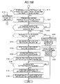
- FIG. 15B is a flowchart (second half) showing the flow of the specimen sorting operation of the specimen putting apparatus
- FIG. 16 is a schematic diagram showing the structure of storage instruction data
- FIG. 17 is a schematic diagram showing the structure of stored rack information
- FIG. 18A is a flowchart showing the flow of a retreated rack information display operation of the specimen putting apparatus
- FIG. 18B is a flowchart showing the flow of a bar-code re-reading operation of the specimen putting apparatus
- FIG. 18C is a flowchart showing the flow of an error information removing operation of the specimen putting apparatus
- FIG. 18D is a flowchart showing the flow of a stored rack removing operation of the specimen putting apparatus
- FIG. 19 is a diagram showing an example of a stored rack list screen
- FIG. 20 is a diagram showing an example of a detailed information screen of a sample rack
- FIG. 21 is a flowchart showing the flow of a measuring order obtaining operation of a system control apparatus
- FIG. 22 is a flowchart showing the flow of a specimen container shape detecting process of the system control apparatus
- FIG. 23 is a flowchart showing the procedure of a blood volume detecting process of the system control apparatus
- FIG. 24 is a schematic diagram for illustrating a process of detecting the width of a specimen container in an image
- FIG. 25 is a schematic diagram for illustrating a process of detecting the positions of the right and left ends of a bar-code label in the image
- FIG. 26 is a schematic diagram for illustrating a process of detecting the position of the lower end of a specimen container in the image
- FIG. 27 is a flowchart showing the procedure of a blood coagulation determining process of the system control apparatus
- FIG. 28 is a schematic diagram for illustrating a process of detecting the position of the left end of a specimen container in an image
- FIG. 29 is a schematic diagram for illustrating a process of detecting the position of the upper end of the bottom portion of the specimen container in the image
- FIG. 30 is a schematic diagram for illustrating a processing area for determining blood coagulation when the detection of the position of a blood surface in the image fails;
- FIG. 31A is a scattergram showing a distribution state related to the B values and the R/B luminance ratios of pixels in the processing area in the image shown in FIG. 29 ;
- FIG. 31B is a scattergram showing a distribution state related to the B values and the R/B luminance ratios of pixels in the processing area in the image shown in FIG. 30 ;
- FIG. 31C is a scattergram showing a distribution state related to the B values and the R/B luminance ratios of pixels in the processing area for blood which is not coagulated;
- FIG. 32 is a flowchart showing the procedure of a sorting instruction process of the system control apparatus
- FIG. 33A is a flowchart showing the procedure of a first transport instruction process of the system control apparatus
- FIG. 33B is a flowchart showing the procedure of a second transport instruction process of the system control apparatus
- FIG. 34A is a flowchart (first half) showing the flow of a process of controlling a transport mechanism by a control section of the specimen transport apparatus;
- FIG. 34B is a flowchart (second half) showing the flow of the process of controlling the transport mechanism by the control section of the specimen transport apparatus;
- FIG. 35A is a flowchart (first half) showing the procedure of a specimen analyzing operation of the blood cell analyzing apparatus according to the embodiment.
- FIG. 35B is a flowchart (second half) showing the procedure of the specimen analyzing operation of the blood cell analyzing apparatus according to the embodiment.
- This embodiment is a specimen processing apparatus sorting specimens into the specimens to be provided for the specimen measurement and the specimens which are not to be provided for the specimen measurement.
- FIG. 1 is a schematic plan view showing the entire configuration of a specimen processing system according to this embodiment.
- a specimen processing system 1 includes a specimen putting apparatus 2 , specimen transport apparatuses 3 and 301 , a specimen accommodating apparatus 4 , a blood cell analyzing apparatus 5 , a smear preparing apparatus 6 , and a system control apparatus 8 .
- the specimen processing system 1 according to this embodiment is connected to a host computer 9 via a communication network so as to communicate therewith.
- the specimen putting apparatus 2 includes a specimen setting section 21 , a specimen checking unit 22 and a specimen feeding unit 23 .
- the specimen putting apparatus 2 can place plural specimen containers accommodated in a sample rack.
- the specimen putting apparatus 2 includes a control section 2 a composed of a CPU and a memory and the control section 2 a can control the operation mechanisms which are the specimen setting section 21 , the specimen checking unit 22 and the specimen feeding unit 23 .
- the specimen putting apparatus 2 is connected to the system control apparatus 8 via a communication network so as to perform data communication with the system control apparatus 8 .
- FIG. 2 is a perspective view showing the appearance of a specimen container
- FIG. 3 is a perspective view showing the appearance of a sample rack.
- a tube-shaped specimen container T is open at a top end thereof.
- the specimen container T contains a blood specimen collected from a patient and the opening at the top end is sealed by a cap section CP.
- the specimen container T is made of translucent glass or synthetic resin and the blood specimen therein can be visually confirmed.
- a bar-code label BL 1 is adhered to a side face of the specimen container T and a bar-code indicating a specimen ID is printed on the bar-code label BL 1 .
- a sample rack L can hold ten specimen containers T in parallel.
- the specimen containers T are held in a vertical state (erect state).
- a bar-code label BL 2 is adhered to a side face of the sample rack L and a bar-code indicating a rack ID is printed on the bar-code label BL 2 .
- FIG. 4 is a plan view showing the configuration of the specimen setting section 21 .
- the specimen setting section 21 has a concave rack placing section 211 for placing the sample rack L accommodating the specimen containers T.
- the rack placing section 211 has a rectangular shape and can simultaneously hold the plural sample racks L.
- the sample racks L are placed in the rack placing section 211 so that the specimen containers T line up in a transverse direction.
- the rack placing section 211 is provided with sensors 212 and 213 for detecting the sample rack L and an engaging section 211 a for moving the sample rack L.
- the sensors 212 and 213 are optical sensors.
- the sensor 212 includes a light-emitting section 212 a and a light-receiving section 212 b
- the sensor 213 includes a light-emitting section 213 a and a light-receiving section 213 b
- the light-emitting section 212 a is positioned at the left-front side of the rack placing section 211 and the light-receiving section 212 b is positioned at the right-center side of the rack placing section 211
- the light-emitting section 213 a is positioned at the left-rear side of the rack placing section 211 and the light-receiving section 213 b is positioned at the right-center side of the rack placing section 211 .
- the light-emitting section 212 a is disposed so as to emit light diagonally in a backward right direction and the light-receiving section 212 b is disposed so as to receive the light over the rack placing section 211 .
- the light-emitting section 213 a is disposed so as to emit light diagonally in a forward right direction and the light-receiving section 213 b is disposed so as to receive the light over the rack placing section 211 .
- the sample rack L is detected by the rack sensor 212 or 213 .
- the sample rack L detected by the rack sensor 212 or 213 is engaged with the engaging section 211 a and the engaging section 211 a is moved in a front-back direction while being engaged with the sample rack L so as to move the sample rack L on the rack placing section 211 .
- the specimen setting section 21 includes a bar-code reading section 21 a at the inner side of the rack placing section 211 .
- the bar-code reading section 21 a includes a specimen bar-code reader 21 b for simultaneously reading the specimen bar-codes of the plural specimen containers T accommodated in the sample rack L and a rack bar-code reader 21 c for reading the rack bar-code of the sample rack L.
- the bar-code reading section 21 a includes a horizontal rotation mechanism 21 d for simultaneous horizontal rotation of the plural specimen containers T directly above a bar-code reading position at the most inner side of the rack placing section 211 .
- the sample rack L put into the rack placing section 211 is moved in a direction toward the inner side from the front side, that is, backward on the rack placing section 211 , to reach the bar-code reading position. After that, while the specimen container T accommodated in the sample rack L is horizontally rotated by the horizontal rotation mechanism 21 d , the specimen ID is read from the bar-code label BL 1 by the specimen bar-code reader 21 b . In addition, the rack ID is read from the bar-code label BL 2 of the sample rack L by the rack bar-code reader 21 c . The read rack ID and specimen ID are transmitted to the system control apparatus 8 .
- the control section 2 a of the specimen putting apparatus 2 transmits specimen-barcode reading error information corresponding to the holding position of the specimen to the system control apparatus 8 .
- the control section 2 a transmits a rack sequential number sequentially assigned to the put sample rack L to the system control apparatus 8 in place of the rack ID.
- a CCD camera 21 e for detecting the shape of a specimen container is provided in front of the bar-code reading position of the specimen setting section 21 .
- a white LED 21 f is disposed at a predetermined position with respect to the camera 21 e and the specimen container T is illuminated by the white LED 21 f .
- the white LED 21 f emits light toward the sample rack L positioned at the bar-code reading position and is disposed so that the reflected light does not directly enter the camera 21 e . Accordingly, the reflected light does not directly hit the camera 21 e and it is possible to prevent so-called halation occurring due to overexposure.
- the CCD camera 21 e and the white LED 21 f can be vertically moved by a vertical driving mechanism (not shown).
- a vertical driving mechanism not shown.
- the CCD camera 21 e and the white LED 21 f are lifted by the vertical driving mechanism up to a position which does not interfere with the movement of the sample rack L.
- the CCD camera 21 e and the white LED 21 f are dropped so as to be positioned in front of the sample rack L and the entire sample rack L is imaged by the CCD camera 21 e.
- specimen setting section 21 is disposed on the right side of the specimen checking unit 22 (see FIG. 1 for reference).
- the sample rack L at the bar-code reading position, in which the rack bar-code and the specimen bar-code have been read, is conveyed to the specimen checking unit 22 from a rack delivery port 215 provided on the left side of the bar-code reading position.
- the specimen setting section 21 is provided with an operating panel 214 .
- a user operates the operating panel 214 so as to issue an analysis start instruction or an analysis completion instruction to the specimen processing system 1 .
- FIG. 5 is a plan view showing the configuration of the specimen checking unit 22 .
- the specimen checking unit 22 includes a specimen container collect section 221 , which has a quadrangular shape when viewed from above, capable of accommodating the plural sample racks L.
- the specimen checking unit 22 includes a handy bar-code reader 222 c which is manually used by a user, a horizontal rotation mechanism 223 for horizontally rotating the specimen container T, an optical sensor 223 a for detecting the presence or absence of the bar-code label BL 1 of the specimen container T, a specimen container tilting mechanism 224 for taking out the specimen container T from the sample rack L and tilting the specimen container T, two cameras 225 a and 225 b for imaging the specimen container T and a liquid crystal display section 227 .
- the liquid crystal display section 227 is a touch panel type display and an input device 227 a is incorporated therein.
- the specimen container collect section 221 is a rectangular recessed portion when viewed from above.
- a rack feed port 221 a for feeding the sample rack L from the specimen setting section 21 is provided in a right wall section at the inner end of the specimen container collect section 221 .
- a rack delivery port 221 b for delivering the sample rack L to the specimen feeding unit 23 is provided in a left wall section at the inner end of the specimen container collect section 221 .
- a transport belt 228 for transporting the sample rack L is provided between the rack feed port 221 a and the rack delivery port 221 b .
- the transport belt 228 is an annular belt and is driven by a stepping motor 228 a so as to transport the sample rack L placed on the transport belt 228 to the left in the drawing.
- a rack feed bar 229 is provided at the further inner side of the transport belt 228 .
- the rack feed bar 229 is driven by a stepping motor 228 a so as to push forward the sample rack L on the transport belt 228 .
- the sample rack L delivered to the front by the rack feed bar 229 is retained by the specimen container collect section 221 .
- the transport belt 228 , the stepping motor 228 a , the rack feed bar 229 , and the stepping motor 229 a functions as a delivery section which is capable of delivering specimen containers toward the specimen transport apparatus 3 and toward the specimen container collect section 221 .
- FIG. 6 is a front view schematically showing the configuration of a part of the specimen checking unit 22 .
- the horizontal rotation mechanism 223 has a contacting section 223 d which is brought into contact with the top end of the specimen container T on the sample rack L, and the contacting section 223 d is configured to be horizontally rotated by a motor.
- the contacting section 223 d is horizontally rotated while brought into contact with the cap section CP of the specimen container T, the specimen container T is horizontally rotated in the sample rack L.
- the optical sensor 223 a is disposed in front of the horizontal rotation mechanism 223 .
- the optical sensor 223 a is composed of a light-emitting element 223 b and a light-receiving element 223 c . While the specimen container T is horizontally rotated by the horizontal rotation mechanism 223 , the specimen container T is irradiated with light from the light-emitting element 223 b and the light reflected is received by the light-receiving element 223 c .
- a light-receiving level of the light-receiving element 223 c exceeds a predetermined value, and when the bar-code label is not disposed on the face reflecting the light of the light-emitting element 223 b , the light-receiving level is equal to or less than the predetermined value.
- the control section 2 a checks the light-receiving level of the light-receiving element 223 c of the optical sensor 223 a while horizontally rotating the specimen container T, and stops the horizontal rotation operation of the horizontal rotation mechanism 223 at a position where the light-receiving level is equal to or less than the predetermined value. Accordingly, an angle of the specimen container T is adjusted so that the face on which the bar-code label BL 1 is not disposed faces the front side.
- the optical sensor 223 a can be vertically moved by a vertical driving mechanism (not shown).
- the optical sensor 223 a is disposed in front of the sample rack L when the sample rack L is on the transport path of the specimen container collect section 221 .
- the optical sensor 223 a is lifted by the vertical driving mechanism up to a position which does not interfere with the movement of the sample rack L.
- FIG. 7 is a side view showing the schematic configuration of the specimen container tilting mechanism 224 .
- the specimen container tilting mechanism 224 includes a grasping section 224 a for grasping the vicinity of the top end of the specimen container from both the right and left sides, a motor 224 b , and a belt 224 c for connecting a rotation shaft of the motor 224 b with the grasping section 224 a , and the grasping section 224 a can be vertically moved by the rotation of the motor 224 b . Furthermore, the grasping section 224 a is connected to a rotation shaft of a motor 224 d and the grasping section 224 a can be rotated around a center axis extending in a front-back direction by the rotation of the motor 224 d.
- the specimen container T which is rotated by the horizontal rotation mechanism 223 so that the bar-code label BL 1 is not disposed on the front face, reaches the position of the specimen container tilting mechanism 224 by moving the sample rack L to the left.
- the grasping section 224 a of the specimen container tilting mechanism 224 grasps the vicinity of the top end of the specimen container T and is lifted in such a state, the specimen container T is taken out from the sample rack L.
- the lifting operation of the grasping section 224 a is stopped.
- the camera 225 a is disposed in front of the specimen container T positioned at the first imaging position 224 e .
- a white LED 225 c is disposed at a predetermined position with respect to the camera 225 a and the specimen container T is illuminated by the white LED 225 c.
- FIG. 8 is a schematic diagram for illustrating a positional relationship between the camera 225 a , the white LED 225 c and the specimen container T, and a direction of the light emitted from the white LED.
- the white LED 225 c is disposed, so that the light is emitted toward the specimen container T positioned at the first imaging position 224 e and the light reflected from the specimen container T does not directly enter the camera 225 a positioned in front of the specimen container T. Accordingly, the camera 225 a is not directly exposed to the reflected light and so-called halation due to overexposure can be prevented.
- the specimen container T grasped at the first imaging position 224 e by the grasping section 224 a is imaged by the camera 225 a while being in an erect state (vertical state), and the image data obtained in this manner is transmitted to the system control apparatus 8 .
- the grasping section 224 a is vertically rotated by the motor 224 d to tilt the specimen container T.
- the grasping section 224 a is turned by a predetermined angle so that a bottom portion of the specimen container T reaches a second imaging position 224 f positioned higher than the cap section CP.
- the camera 225 b see FIG.
- a white LED 225 d (see FIG. 5 for reference) is disposed at a predetermined position with respect to the camera 225 b and the specimen container T is illuminated by the white LED 225 d .
- a relative positional relationship between the white LED 225 d and the camera 225 b is the same as a relative positional relationship between the white LED 225 c and the camera 225 a .
- the white LED 225 d is disposed, so that the light is emitted toward the specimen container T positioned at the second imaging position 224 f , and the light reflected from the specimen container T does not directly enter the camera 225 b positioned in front of the specimen container T.
- the specimen container T grasped at the second imaging position 224 f by the grasping section 224 a is imaged by the camera 225 a while being tilted as described above, and the image data obtained in this manner is transmitted to the system control apparatus 8 .
- the sample rack L in which all the specimen containers T have been imaged is delivered from the rack delivery port 221 b by the transport belt 228 .
- the bar-code reader 222 c is provided with a light-emitting section and a light-receiving section (line sensor) (not shown), and is connected to the main body of the specimen checking unit 22 by a flexible cable for transmitting an electric signal.
- the bar-code reader 222 c is operated when a user manually re-reads a bar-code which cannot be read by the bar-code reading section 21 a.
- the specimen feeding unit 23 disposed on the left side of the specimen checking unit 22 includes a rack re-putting section 231 in which the plural sample racks L are placed (see FIG. 1 for reference).
- the rack re-putting section 231 has the same rectangular parallelepiped shape as the rack placing section 211 of the specimen setting section 21 , when viewed from above.
- the sample rack L fed from the rack feed port is moved to the front by the rack re-putting section 231 so as to reach the most forward position and is then delivered to the left from the rack delivery port.
- the specimen feeding unit 23 is provided with a bar-code reader 23 a for reading a rack bar-code.
- the bar-code reader By using the bar-code reader, the rack ID of the sample rack L transported to the rack re-putting section 231 is read, and before the sample rack L is transported to the following specimen transport apparatus 3 , convey request data including the rack ID is transmitted to the system control apparatus 8 .
- the specimen processing system 1 includes 3 specimen transport apparatuses 3 .
- the specimen transport apparatuses 3 , 3 and 3 are each disposed in front of three measuring units 51 , 51 and 51 of the blood cell analyzing apparatuses 5 .
- Neighboring specimen transport apparatuses 3 and 3 are connected to each other so as to send and receive a sample rack L between each other.
- the rightmost specimen transport apparatus 3 is connected to the above-described specimen putting apparatus 2 so as to introduce the sample rack L conveyed from the specimen putting apparatus 2 thereto.
- the leftmost specimen transport apparatus 3 is connected to the specimen transport apparatus 301 to convey the sample rack L to the specimen transport apparatus 301 .
- FIG. 9 is a plan view showing the configuration of the specimen transport apparatus 3 .
- the specimen transport apparatus 3 includes a transport mechanism 31 for transporting a specimen and a control section 32 for controlling the transport mechanism 31 .
- the transport mechanism 31 includes a before-analysis rack holding section 33 capable of temporarily holding the plural sample racks L holding the specimen containers T accommodating the specimens before the analysis is performed, an after-analysis rack holding section 34 capable of temporarily holding the plural sample racks L holding the specimen containers T in which the specimen is aspirated by the measuring unit 51 , a rack transport section 35 for horizontally moving the sample rack L in a straight line in a direction of the arrow X in the drawing so as to supply the specimen to the measuring unit 51 and transporting the sample rack L received from the before-analysis rack holding section 33 to the after-analysis rack holding section 34 , and a rack transport section 321 for conveying the sample rack L from the apparatus (specimen putting apparatus 2 or specimen transport apparatus 3 ) on the upstream side of the transport and conveying the sample rack L to
- the before-analysis rack holding section 33 has a quadrangular shape when viewed from above, and its width is slightly larger than the width of the sample rack L.
- the before-analysis rack holding section 33 is formed to be lower by one stage than the surrounding surface, and on an upper face thereof, the sample racks L before analysis are placed.
- the before-analysis rack holding section 33 is connected to the rack transport section 321 , and the sample rack L is sent from the rack transport section 321 by a rack delivery section 322 to be described later.
- a rack sensor 37 is installed near the before-analysis rack holding section 33 , and a rack detection position 33 a at which the sample rack L is detected by the rack sensor 37 is provided on the before-analysis rack holding section 33 .
- the rack sensor 37 is an optical sensor and includes a light-emitting section 37 a and a light-receiving section 37 b .
- the light-emitting section 37 a is provided adjacent to the rack detection position 33 a and the light-receiving section 37 b is provided in front of the rack detection position 33 a .
- the light-emitting section 37 a is disposed so as to emit light diagonally in a forward direction and the light-receiving section 37 b is disposed so as to receive the light. Accordingly, the sample rack L sent from the rack transport section 321 is positioned at the rack detection position 33 a and the light emitted from the light-emitting section 37 a is thus blocked by the sample rack L.
- rack sending sections 33 b are provided in both faces of the before-analysis rack holding section 33 so as to be protruded inward.
- the rack sending sections 33 b protrude so as to be engaged with the sample rack L.
- the rack sending sections 33 b are moved backward (moved in a direction to be close to the rack transport section 35 ) and thus the sample rack L is moved backward.
- the rack sending sections 33 b are configured to be driven by a stepping motor 33 c provided below the before-analysis rack holding section 33 .
- the rack transport section 35 can move the sample rack L, which is moved by the before-analysis rack holding section 33 , in the X direction.
- On the path of the transport of the sample rack L by the rack transport section 35 there are a specimen container detection position 35 a where the specimen container is detected by a specimen container sensor 38 and a specimen supply position 35 c for supplying the specimen to the measuring unit 51 of the blood cell analyzing apparatus 5 .
- the rack transport section 35 is configured to transport the sample rack L via the specimen container detection position 35 a so that the specimen is transported to the specimen supply position 35 c .
- the specimen supply position 35 c is positioned on the downstream side in the transport direction so as to be separated from the specimen container detection position 35 a by the distance corresponding to one specimen.
- a band section of the measuring unit 51 of the blood cell analyzing apparatus 5 to be described later grasps the specimen container T for the specimen and takes out the specimen container T from the sample rack L so as to aspirate the specimen from the specimen container T, and thus the specimen is supplied to the measuring unit 51 .
- the rack transport section 35 stands by to transport the sample rack L while the supply of the specimen is completed and the specimen container T is returned to the sample rack L.
- the rack transport section 35 has two independently operable belts, that is, a first belt 351 and a second belt 352 .
- Widths b 1 and b 2 in a direction of the arrow Y of the first belt 351 and the second belt 352 are equal to or smaller than half of a width B in the direction of the arrow Y of the sample rack L.
- the first belt 351 and the second belt 352 are disposed in parallel so as not to protrude from the width B of the sample rack L when the rack transport section 35 transports the sample rack L.
- FIG. 10 is a front view showing the configuration of the first belt 351
- FIG. 11 is a front view showing the configuration of the second belt 352 . As shown in FIGS.
- the first belt 351 and the second belt 352 are annularly formed.
- the first belt 351 is disposed so as to surround rollers 351 a to 351 c and the second belt 352 is disposed so as to surround rollers 352 a to 352 c .
- two protrusions 351 d are provided so as to have an inner width w 1 slightly larger (for example, 1 mm) than a width W in the X direction of the sample rack L, and similarly, in a peripheral section of the second belt 352 , two protrusions 352 d are provided so as to have the same inner width w 2 as the inner width w 1 .
- the first belt 351 is configured so that the sample rack L held inside of the two protrusions 351 d is moved in the direction of the arrow X by being moved along the peripheries of the rollers 351 a to 351 c by a stepping motor 351 e (see FIG. 9 for reference).
- the second belt 352 is configured so that the sample rack L held inside of the two protrusions 352 d is moved in the direction of the arrow X by being moved along the peripheries of the rollers 352 a to 352 c by a stepping motor 352 e (see FIG. 9 for reference).
- the first belt 351 and the second belt 352 are configured so as to move the sample rack L independently of each other.
- the specimen container sensor 38 is a contact sensor and has a curtain-like contact piece, a light-emitting element emitting light and a light-receiving element (not shown).
- the specimen container sensor is configured so that the contact piece is bent when brought into contact with a substance to be detected which is a detection object and the light emitted from the light-emitting element is thus reflected by the contact piece and enters the light-receiving element. Accordingly, while the specimen container T as a detection object accommodated in the sample rack L passes under the specimen container sensor 38 , the contact piece is bent by the specimen container T and the specimen container T can be detected.
- a rack delivery section 39 is disposed so as to be opposed to the after-analysis rack holding section 34 to be described later with the rack transport section 35 interposed therebetween.
- the rack delivery section 39 is configured to be horizontally moved in a straight line in the direction of the arrow Y by a driving force of a stepping motor 39 a . Accordingly, when the sample rack L is transported to a position 391 (hereinafter, referred to as “after-analysis rack delivery position”) between the after-analysis rack holding section 34 and the rack delivery section 39 , by moving the rack delivery section 39 toward the after-analysis rack holding section 34 , the sample rack L is pushed so as to be moved to the inside of the after-analysis rack holding section 34 . In this manner, the sample rack L in which the analysis is completed is delivered to the after-analysis rack holding section 34 from the rack transport section 35 .
- the rack transport section 321 extends in the direction of the arrow X in the drawing and can horizontally move the sample rack L in a straight line in the direction of the arrow X.
- the rack transport section 321 has an annular belt 321 a and a stepping motor 321 b and is configured so as to rotate the belt 321 a in the direction of the arrow X by a driving force of the stepping motor 321 b . Accordingly, the sample rack L placed on the belt 321 a can be moved in the X direction.
- the rack delivery section 322 is disposed in front of the before-analysis rack holding section 33 so as to be opposed to the before-analysis rack holding section 33 with the rack transport section 321 interposed therebetween.
- the rack delivery section 322 is configured to be horizontally moved in a straight line in the direction of the arrow Y by a driving force of a stepping motor 322 a . Accordingly, when the sample rack L is transported to a position 323 (hereinafter, referred to as “before-analysis rack delivery position”) between the before-analysis rack holding section 33 and the rack delivery section 322 , by moving the rack delivery section 322 toward the before-analysis rack holding section 33 , the sample rack L is pushed so as to be moved to the rack detection position 33 a in the before-analysis rack holding section 33 .
- the after-analysis rack holding section 34 has a quadrangular shape when viewed from above, and its width is slightly larger than the width of the sample rack L.
- the after-analysis rack holding section 34 is formed to be lower by one stage than the surrounding surface, and on an upper face thereof, the sample racks L in which the analysis is completed are placed.
- the after-analysis rack holding section 34 is connected to the rack transport section 35 , and as described above, the sample rack L is sent from the rack transport section 35 by the rack delivery section 39 .
- Rack sending sections 34 b are provided in both faces of the after-analysis rack holding section 34 so as to protrude inward. When the sample rack L is conveyed by the rack delivery section 39 , the rack sending sections 34 b protrude so as to be engaged with the sample rack L.
- the rack sending sections 34 b are configured to be driven by a stepping motor 34 c provided below the after-analysis rack holding section 34 .
- a measuring line L 1 which is used as a transport line for the sample rack L passing through the specimen supply position 35 c
- a skip line L 2 which is used as a transport line for conveying the sample rack L not passing through the specimen supply position 35 c to the apparatus on the downstream side, are formed in the transport mechanism 31 .
- the transport mechanism 31 having the above-described configuration is controlled by the control section 32 .
- the control section 32 is composed of a CPU, a ROM, a RAM and the like (not shown) and a control program of the transport mechanism 31 , which is stored in the ROM, can be executed by the CPU.
- the control section 32 includes an Ethernet (registered trade name) interface and is connected to an information processing unit 52 and the system control apparatus 8 via a LAN so as to communicate therewith.
- the specimen transport apparatus 3 transports the sample rack L, which is transported from the specimen putting apparatus 2 , to the before-analysis rack delivery position 323 by using the rack transport section 321 , moves the sample rack to the before-analysis rack holding section 33 by using the rack delivery section 322 , delivers the sample rack L to the rack transport section 35 from the before-analysis rack holding section 33 , and also transports the sample rack by using the rack transport section 35 , and thus the specimen can be supplied to the measuring unit 51 of the blood cell analyzing apparatus 5 .
- the sample rack L which accommodates the specimens for which the aspiration have been completed, is moved to the after-analysis rack delivery position 391 by the rack transport section 35 and is delivered to the after-analysis rack holding section 34 by the rack delivery section 39 .
- the sample rack L held in the after-analysis rack holding section 34 is moved to the rack transport section 321 and is conveyed to the following apparatus (specimen transport apparatus 3 or 301 ) by the rack transport section 321 .
- the sample rack L which accommodates the specimens to be processed by the measuring unit 51 or the smear preparing apparatus 6 on the downstream side of the transport or the specimens in which the analysis is completed, is received by the specimen transport apparatus 3 from the preceding apparatus, the sample rack L is transported in the direction of the arrow X by the rack transport section 321 and is conveyed to the following specimen transport apparatus 3 .
- the specimen transport apparatus 301 is disposed in front of the smear preparing apparatus 6 .
- the right end of the specimen transport apparatus 301 is connected to the specimen transport apparatus 3 positioned on the downmost-stream side of the transport (left side in the drawing) among the three specimen transport apparatuses 3 , 3 and 3 .
- the left end of the specimen transport apparatus 301 is connected to the specimen accommodating apparatus 4 .
- the specimen transport apparatus 301 includes a conveyor 302 and a rack slider 303 .
- the conveyor 302 is provided with two rack transport paths 302 a and 302 b extending in a horizontal direction.
- the rack transport path 302 a which is close to the smear preparing apparatus 6 is a measuring line for transporting the sample rack L accommodating the specimen to be supplied to the smear preparing apparatus 6 .
- the rack transport path 302 b which is separated from the smear preparing apparatus 6 is a skip line for transporting the sample rack L not accommodating the specimen to be supplied to the smear preparing apparatus 6 .
- the conveyor 302 includes a CPU, a memory and a control section (not shown) for controlling the operating mechanisms.
- the rack slider 303 is disposed on the right side of the conveyor 302 , and sorts and puts the sample racks L to the measuring line 302 a and the skip line 302 b of the conveyor 302 .
- the specimen accommodating apparatus 4 is configured so as to place the plural sample racks L.
- the specimen accommodating apparatus 4 receives from the specimen transport apparatus 301 the sample rack L in which the analysis or the smear preparation is completed, and accommodates the sample rack L.
- the blood cell analyzing apparatus 5 which is used as an optical flow cytometry type multiple blood cell analyzing apparatus, obtains the fluorescent intensity, the side-scattered light intensity and the like of blood cells included in a blood specimen, classifies the blood cells included in the specimen on the basis of the above intensities, and counts the number of blood cells for each type. Moreover, the blood cell analyzing apparatus 5 creates a scattergram in which the classified blood cells are color-coded for each type, and displays the scattergram.
- the blood cell analyzing apparatus 5 includes a measuring unit 51 for measuring a blood specimen and an information processing unit 52 for processing measuring data output from the measuring unit 51 and displaying an analysis result of the blood specimen.
- the blood cell analyzing apparatus 5 includes the three measuring units 51 , 51 and 51 and one information processing unit 52 .
- the information processing unit 52 is connected to the three measuring units 51 , 51 and 51 so as to communicate therewith and can control the operations of the three measuring units 51 , 51 and 51 .
- the information processing unit 52 is also connected to the three specimen transport apparatuses 3 , 3 and 3 , which are respectively disposed in front of the three measuring units 51 , 51 and 51 , so as to communicate therewith.
- FIG. 12 is a block diagram showing the configuration of the measuring unit 51 .
- the measuring unit 51 includes a specimen aspirating section 511 for aspirating blood as a specimen from the specimen container (blood collection tube) T, a sample preparing section 512 for preparing a measurement sample which is used in the measurement from the blood aspirated by the specimen aspirating section 511 and a detecting section 513 for detecting a blood cell from the measurement sample prepared by the sample preparing section 512 .
- the measuring unit 51 further has a taking port (not shown) for taking the specimen container T accommodated in the sample rack L transported by the rack transport section 35 of the specimen transport apparatus 3 into the measuring unit 51 , and a specimen container transport section 515 for taking the specimen container T from the sample rack L into the measuring unit 51 and transporting the specimen container T to an aspiration position where the aspiration is performed by the specimen aspirating section 511 .
- An aspiration tube (not shown) is provided at the tip end of the specimen aspirating section 511 .
- the specimen aspirating section 511 can be vertically moved and is configured to be moved downward so that the aspiration tube penetrates into the cap section CP of the specimen container T transported to the aspiration position so as to aspirate the blood in the specimen container.
- the sample preparing section 512 includes plural reaction chambers (not shown). Further, the sample preparing section 512 is connected to a reagent container (not shown) and can supply reagents such as a smearing reagent, a hemolytic agent and a diluent to the reaction chamber. The sample preparing section 512 is also connected to an aspiration tube of the specimen aspirating section 511 and can supply the blood specimen aspirated by the aspiration tube to the reaction chamber. The sample preparing section 512 mixes and stirs the specimen and the reagent in the reaction chamber to prepare a sample (measurement sample) for the measurement by the detecting section 513 .
- a sample measurement sample
- the detecting section 513 can detect red blood cells (RBC) and platelets (PLT) by a sheath flow DC detection method.
- RBC red blood cells
- PLT platelets
- a measurement sample is measured in which a specimen and a diluent are mixed, and measuring data obtained in this manner is analyzed by the information processing unit 52 so as to measure the RBCs and PLTs.
- the detecting section 513 is configured to detect hemoglobin (HGB) by a SLS-hemoglobin method and detect white blood cells (WBC), neutrophils (NEUT), lymphocytes (LYMPH), eosinophils (EO), basophil (BASO) and monocytes (MONO) by a flow cytometry method using semiconductor lasers.
- WBC white blood cells
- NEUT neutrophils
- LYMPH lymphocytes
- EO eosinophils
- BASO basophil
- CMS monocytes
- the detection of WBCs unaccompanied by 5 classifications of white blood cells that is, the detection of WBCs unaccompanied by the detection of NEUTs, LYMPHs, EOs, BASOs and MONOs is different in detection method from the detection of WBCs accompanied by 5 classifications of white blood cells.
- a measurement sample is measured in which a specimen, a hemolytic agent and a diluent are mixed, and measuring data obtained in this manner is analyzed by the information processing unit 52 so as to measure WBCs.
- a measurement sample is measured in which a smearing reagent, a hemolytic agent and a diluent are mixed, and measuring data obtained in this manner is analyzed by the information processing unit 52 so as to measure NEUTs, LYMPHs, EOs, BASOs, MONOs and WBCs.
- the specimen container transport section 515 includes a hand section 515 a capable of grasping the specimen container T.
- the hand section 515 a includes a pair of grasping members opposed to each other and can allow the grasping members to be close to each other or separated from each other.
- the specimen container T can be held by allowing the grasping members with the specimen container T interposed therebetween to be close to each other.
- the specimen container transport section 515 can move the hand section 515 a in a vertical direction and in a front-back direction (Y direction) and can oscillate the hand section 515 a .
- the specimen container T accommodated in the sample rack L is held by holding the specimen container T accommodated in the sample rack L and positioned at the supply position 35 c with the hand section 515 a and moving the hand section 515 a upward, the specimen container T is pulled out of the sample rack L, and by oscillating the hand section 515 a , the specimen in the specimen container T can be stirred.
- the specimen container transport section 515 includes a specimen container setting section 515 b having a hole to which the specimen container T can be inserted.
- the specimen container T grasped by the above-described hand section 515 a is moved after the completion of stirring and the grasped specimen container T is inserted to the hole of the specimen container setting section 515 b .
- the specimen container T is released from the hand section 515 a and the specimen container T is set in the specimen container setting section 515 b .
- the specimen container setting section 515 b can be horizontally moved in the Y direction by the power of a stepping motor (not shown).
- a bar-code reading section 516 is provided in the measuring unit 51 .
- the specimen container setting section 515 b can be moved to a bar-code reading position 516 a near the bar-code reading section 516 and an aspiration position 511 a where the aspiration is performed by the specimen aspirating section 511 .
- the specimen container setting section 515 b is moved to the bar-code reading position 516 a
- the set specimen container T is horizontally rotated by a rotation mechanism (not shown) and the specimen bar-code is read by the bar-code reading section 516 .
- the bar-code label BL 1 of the specimen container T can face the bar-code reading section 516 by rotating the specimen container T and the bar-code reading section 516 can read the specimen bar-code.
- the specimen container setting section 515 b is moved to the aspiration position, the specimen is aspirated from the set specimen container T by the specimen aspirating section 511 .
- FIG. 13 is a block diagram showing the configuration of the information processing unit 52 .
- the information processing unit 52 is realized by a computer 52 a .
- the computer 52 a includes a main body 521 , an image display section 522 and an input section 523 .
- the main body 521 includes a CPU 521 a , a ROM 521 b , a RAM 521 c , a hard disk 521 d , a reading device 521 e , an I/O interface 521 f , a communication interface 521 g and an image output interface 521 h .
- the CPU 521 a , ROM 521 b , RAM 521 c , hard disk 521 d , reading device 521 e , I/O interface 521 f , communication interface 521 g and image output interface 521 h are connected to each other by a bus 521 j.
- the CPU 521 a can execute a computer program loaded to the RAM 521 c .
- the CPU 521 a executes a computer program 524 a for analyzing a specimen and controlling the measuring unit 51 , which will be described later, so that the computer 52 a functions as the information processing unit 52 .
- the ROM 521 b is composed of a mask ROM, a PROM, an EPROM, an EEPROM or the like and the computer program which is executed by the CPU 521 a and data which is used for the computer program are recorded in the ROM.
- the RAM 521 c is composed of a SRAM, a DRAM or the like.
- the RAM 521 c is used to read the computer program 524 a recorded in the hard disk 521 d .
- the RAM is used as an operating area of the CPU 521 a when the CPU 521 a executes a computer program.
- various computer programs for being executed by the CPU 521 a such as an operating system and an application program, and data which are used to execute the computer programs are installed.
- the computer program 524 a to be described later is also installed in the hard disk 521 d.
- the reading device 521 e is composed of a flexible disk drive, a CD-ROM drive, a DVD-ROM drive or the like and can read the computer program or data recorded in a portable recording medium 524 .
- the computer program 524 a for prompting the computer to function as the information processing unit 52 is stored.
- the computer 52 a can read the computer program 524 a from the portable recording medium 524 and install the computer program 524 a in the hard disk 521 d.
- the computer program 524 a is provided by the portable recording medium 524 and can be also provided from an external device, which is connected to the computer 52 a by an electric communication line (which may be wired or wireless) so as to communicate therewith, through the electric communication line.
- the computer program 524 a is stored in a hard disk of a server computer on the internet and the computer 52 a accesses the server computer so as to download the computer program and install the computer program in the hard disk 521 d.
- the computer program 524 a operates on the above operating system.
- the I/O interface 521 f is composed of, for example, a serial interface such as USB, IEEE1394 or RS-232C, a parallel interface such as SCSI, IDE or IEEE 1284, and an analog interface including a D/A converter and an A/D converter.
- the input section 523 composed of a keyboard and a mouse is connected to the I/O interface 521 f and a user uses the input section 523 so as to input data to the computer 52 a .
- the I/O interface 521 f is connected to the three measuring units 51 , 51 and 51 so as to send and receive data to and from the respective three measuring units 51 , 51 and 51 .
- the communication interface 521 g is an Ethernet (registered trade name) interface.
- the communication interface 521 g is connected to the system control apparatus 8 via a LAN.
- the computer 52 a can send and receive data to and from the system control apparatus 8 connected to the LAN by using a predetermined communication protocol.
- the communication interface 521 g is connected to the host computer 9 and each of the specimen transport apparatus 3 , 3 , and 3 via the LAN so as to communicate therewith.
- the image output interface 521 h is connected to the image display section 522 composed of a LCD or a CRT so as to output a picture signal corresponding to the image data provided from the CPU 521 a to the image display section 522 .
- the image display section 522 displays an image (screen) in accordance with an input picture signal.
- the smear preparing apparatus 6 aspirates a blood specimen so as to deliver it onto a slide glass by drops, spreads and dries the blood specimen on the slide glass, and supplies a stain solution to the slide glass so as to stain the blood on the slide glass. In this manner, the smear preparing apparatus prepares a smear.
- FIG. 14 is a block diagram showing the schematic configuration of the smear preparing apparatus 6 .
- the smear preparing apparatus 6 includes a specimen dispensing section 61 , a smearing section 62 , a slide glass transport section 63 , a staining section 64 and a control section 65 .
- the specimen dispensing section 61 includes an aspiration tube (not shown) and the aspiration tube is stuck into the cap section CP of a specimen container T in the sample rack L transported on the measuring line 31 a of the specimen transport apparatus 3 so as to aspirate a blood specimen from the specimen container T.
- the specimen dispensing section 61 is configured to drop the aspirated blood specimen onto a slide glass.
- the smearing section 62 is configured to smear and dry the blood specimen dropped onto the slide glass and perform printing on the slide glass.
- the slide glass transport section 63 is provided to accommodate the slide glass on which the blood specimen is smeared by the smearing section 62 in a cassette (not shown) and to transport the cassette.
- the staining section 64 supplies a stain solution to the slide glass in the cassette transported to a staining position by the slide glass transport section 63 .
- the control section 65 controls the specimen dispensing section 61 , the smearing section 62 , the slide glass transport section 63 and the staining section 64 in accordance with a smear preparing instruction issued from the specimen transport apparatus 3 so as to perform the above smear preparing operation.
- the system control apparatus 8 is composed of a computer and controls the entire specimen processing system 1 .
- the system control apparatus 8 receives the number of the sample rack L from the specimen putting apparatus 2 and determines the transport destination of the sample rack L.
- the system control apparatus 8 is realized by a computer 8 a .
- the computer 8 a includes a main body 81 , an image display section 82 and an input section 83 .
- the main body 81 includes a CPU 81 a , a ROM 81 b , a RAM 81 c , a hard disk 81 d , a reading device 81 e , an I/O interface 81 f , a communication interface 81 g and an image output interface 81 h .
- the CPU 81 a , ROM 81 b , RAM 81 c , hard disk 81 d , reading device 81 e , I/O interface 81 f , communication interface 81 g and image output interface 81 h are connected to each other by a bus 81 j.
- various computer programs for being executed by the CPU 81 a such as an operating system and an application program, and data which are used to execute the computer programs are installed.
- a system control program 84 a to be described later is also installed in the hard disk 81 d.
- the reading device 81 e is composed of a flexible disk drive, a CD-ROM drive, a DVD-ROM drive or the like and can read the computer program or data recorded in a portable recording medium 84 .
- the system control program 84 a for prompting the computer to function as the system control apparatus 8 is stored.
- the computer 8 a can read the system control program 84 a from the portable recording medium 84 so as to install the system control program 84 a in the hard disk 81 d.
- the I/O interface 81 f is composed of, for example, a serial interface such as USB, IEEE 1394 or RS-232C, a parallel interface such as SCSI, IDE or IEEE1284, and an analog interface including a D/A converter and an A/D converter.
- the input section 83 composed of a keyboard and a mouse is connected to the I/O interface 81 f and a user uses the input section 83 so as to input data to the computer 52 a.
- the communication interface 81 g is an Ethernet (registered trade name) interface.
- the communication interface 81 g is connected to the specimen putting apparatus 2 , the specimen transport apparatus 3 , the specimen accommodating apparatus 4 , the information processing unit 52 and the host computer 9 via a LAN.
- the computer 8 a can send and receive data to and from the above respective apparatuses connected to the LAN by using a predetermined communication protocol.
- the host computer 9 is composed of a computer and includes a CPU, a ROM, a RAM, a hard disk, a communication interface and the like.
- the communication interface is connected to the above-described LAN so as to communicate with the system control apparatus 8 and the information processing unit 52 of the blood cell analyzing apparatus 5 .
- the measuring orders include specimen IDs and information on measuring items of objects.
- the host computer 9 When receiving request data for a measuring order including a specimen ID from another apparatus, the host computer 9 reads measuring data corresponding to the specimen ID from the hard disk and transmits the measuring data to the apparatus as a request source. Since the other configurations of the host computer 9 are the same as the configurations of the above-described other computers, a description thereof will be omitted.
- FIGS. 15A and 15B are flowcharts showing the flow of the specimen sorting operation of the specimen putting apparatus 2 .
- a user places the sample rack L accommodating the specimen containers T on the rack placing section 211 of the specimen setting section 21 and operates the operating panel 214 of the specimen setting section 21 so as to issue an analysis start instruction to the specimen processing system 1 .
- the control section 2 a of the specimen putting apparatus 2 detects the sample rack L put into the rack placing section 211 by the sensors 212 and 213 when receiving the analysis start instruction (Step S 101 ).
- the control section 2 a starts the movement of the sample rack L.
- the sample rack L placed on the rack placing section 211 of the specimen setting section 21 is moved backward on the rack placing section 211 and reaches the bar-code reading position (Step S 102 ).
- the control section 2 a reads the specimen IDs of the specimens accommodated in the sample rack L and the rack ID of the sample rack L by the bar-code readers 21 b and 21 c (Step S 103 ).
- each of the specimen containers T is horizontally rotated by the horizontal rotation mechanism 21 d while being held in the sample rack L, and the specimen bar-code is read when the bar-code label BL 1 faces the bar-code reader 21 b .
- the control section 2 a transmits the read specimen IDs and rack IDs to the system control apparatus 8 (Step S 104 ).
- holding positions ( 1 to 10 ) of the specimen containers T in the sample rack L correspond to the specimen IDs of the held specimen containers.
- data is transmitted indicating the reading failure of the specimen bar-code associated with the holding position.
- control section 2 a lowers the CCD camera 21 e and the white LED 21 f , which have been retreated upward so as not to interfere with the movement of the sample rack L on the rack placing section 211 , so as to transmit a first image taking instruction signal to the system control apparatus 8 (Step S 105 ).
- the system control apparatus 8 takes an image captured by the camera 21 e when receiving the first image taking instruction signal, and then performs image processing on the image and detects the shape of the specimen container accommodated in the sample rack L. Then, the control section 2 a moves the sample rack L to the left so as to deliver the sample rack L to the specimen checking unit 22 .
- the control section 2 a moves the sample rack L, which is introduced into the specimen checking unit 22 , to the left for every pitch by the transport belt 228 of the specimen container collect section 221 (Step S 106 ).
- the control section 2 a determines whether the specimen container T is positioned in front of the horizontal rotation mechanism 223 (Step S 107 ). This process is performed by referring to, for example, a light-receiving level of the light-receiving element 223 c of the optical sensor 223 a .
- the control section 2 a performs a process of Step S 109 .
- Step S 108 the control section 2 a drives the horizontal rotation mechanism 223 so as to horizontally rotate the specimen container T to thereby turn the bar-code label BL 1 to the front.
- the control section 2 a compares a light-receiving level of the light-receiving element 223 c of the optical sensor 223 a with a predetermined value while bringing the contacting section 223 d into contact with the cap section CP of the specimen container T and rotating the contacting section, and horizontally rotates the specimen container T until the light-receiving level is equal to or more than the predetermined value. In this manner, the bar-code label BL 1 is turned to the front.
- Step S 109 the controller 2 a determines whether the specimen container T is disposed in front of the specimen container tilting mechanism 224 (Step S 109 ). This process is performed by, for example, determining how many times the specimen container T disposed in front of the horizontal rotation mechanism 223 has been subjected to pitch feeding.
- the controller 2 a performs a process of Step S 115 .
- Step S 109 the controller 2 a grasps the specimen container T by the grasping section 224 a so as to lift the specimen container to the first imaging position on the upper side (Step S 110 ), and transmits a second image taking instruction signal to the system control apparatus 8 (Step S 111 ).
- the system control apparatus 8 takes an image captured by the camera 225 a when receiving the second image taking instruction signal, and then performs image processing on the image and detects the blood volume in the specimen container T.
- the controller 2 a vertically turns the grasping section 224 a by a predetermined angle so as to tilt the specimen container T to the second imaging position (Step S 112 ) and transmits a third image taking instruction signal to the system control apparatus 8 (Step S 113 ).
- the system control apparatus 8 takes an image captured by the camera 225 b when receiving the third image taking instruction signal, and then performs image processing on the image and determines the presence or absence of blood coagulation in the specimen container T.
- the controller 2 a turns the grasping section 224 a in the counter direction to return the specimen container T to the vertical state again, and moves the grasping section 224 a downward so as to accommodate the specimen container T in the sample rack L (Step S 114 ).
- Steps S 107 to S 108 and the processes of Steps S 109 to S 114 have been described so as to be sequentially performed. However, actually, the processes are performed in parallel. That is, for example, while one specimen container T stored in the sample rack L is horizontally rotated, a different specimen container T is pulled from the sample rack L of the specimen containers T.
- the controller 2 a determines whether all the specimen containers T stored in the sample rack L have been subjected to the above processes, or more precisely, whether a specimen container accommodating section at the right end of the sample rack L is positioned in front of the specimen container tilting mechanism 224 (Step S 115 ).
- the controller moves the sample rack L to the left by one pitch (Step S 116 ) and returns the process to Step S 107 .
- the control section 2 a transmits sorting preparation completion data to the system control apparatus 8 (Step S 117 ) and then stands by to receive transport instruction data or storage instruction data (No in Step S 118 ).
- the transport instruction data is transmitted from the system control apparatus 8 when the sample rack L accommodates only the specimens to be provided for the blood cell analysis of the blood cell analyzing apparatus 5
- the storage instruction data is transmitted from the system control apparatus 8 when the sample rack L accommodates a specimen which is not to be provided for the blood cell analysis of the blood cell analyzing apparatus 5 .
- FIG. 16 is a schematic diagram showing the structure of the storage instruction data.
- Storage instruction data D 1 includes the rack ID of the sample rack L, the holding positions ( 1 to 10 ) of the specimen containers T in the sample rack L, the specimen IDs of the specimen containers T and error information (abnormal code) indicating the contents of abnormality.
- the holding position, the specimen ID and the error information of the specimen container T correspond to each other, and the holding position, the specimen ID and the error information of the specimen container T in which an error has occurred can be specified.
- Step S 119 when the received data is the storage instruction data (No in Step S 119 ), the control section 2 a adds the information on the sample rack L to the stored rack information in the memory of the control section 2 a on the basis of the storage instruction data (Step S 120 ).
- FIG. 17 is a schematic diagram showing the structure of the stored rack information.
- stored rack information D 2 includes the rack IDs, the specimen IDs of the holding positions and the error information of the holding positions.
- the specimen ID and the error information correspond to each other, and it is possible to specify which specimen has which kind of error.
- the control section 2 a moves the sample rack L to the specimen container collect section 221 by using the rack delivery section 229 (Step S 121 ) and completes the process.
- Step S 119 when the received data is the transport instruction data (Yes in Step S 119 ), the control section 2 a further moves the sample rack L to the left so as to deliver the sample rack L to the specimen feeding unit 23 (Step S 122 ).
- the control section 2 a reads the rack bar-code of the sample rack L by using the bar-code reader 23 a (Step S 123 ) and moves the sample rack L to the rack conveying position for conveying the sample rack L to the following specimen transport apparatus 3 (Step S 124 ).
- the control section 2 a transmits conveyance request data including the rack ID of the sample rack L to the system control apparatus 8 (Step S 125 ) and stands by to receive conveyance instruction data to be transmitted from the system control apparatus 8 (No in Step S 126 ).
- the specimen putting apparatus 2 conveys the sample rack L to the adjacent specimen transport apparatus 3 (Step S 127 ) and transmits conveyance completion data to the system control apparatus 8 (Step S 128 ). After that, the control section 2 a completes the process.
- FIG. 18A is a flowchart showing the flow of the retreated rack information display operation.
- FIG. 19 is a diagram showing an example of the stored rack list screen.
- a list display area A 1 is provided in which the rack IDs of the sample racks L in which an abnormality has been detected are displayed as a list.
- an operator touches each rack ID with a finger so as to select the rack ID.
- the selected rack ID is displayed with a color different from that of the rack IDs which are not selected.
- a display switching button B 1 is provided for switching the screen display into a detailed information screen of the rack ID selected in the list display area A 1 .
- the control section 2 a When accepting the selection of the rack ID from the operator and a display instruction of the detailed information screen of the sample rack L (Step S 132 ), the control section 2 a displays the detailed information screen on the liquid crystal display section 227 (Step S 133 ).
- the operator may not operate the touch panel so as to select the rack ID and input the display instruction of the detailed information screen, but may read the rack bar-code of the sample rack L by the handy bar-code reader 222 c so as to input the read rack ID to the control section 2 a to thereby display the detailed information screen of the sample rack L.
- the control section 2 a After displaying the detailed information screen, the control section 2 a completes the process.
- FIG. 20 is a diagram showing an example of the detailed information screen of the sample rack L.
- a detailed information screen W 2 includes a rack ID 200 a , holding position numbers 200 b in the sample rack and error information 200 c and 200 d corresponding to the holding positions.
- the error information 200 c is information indicating the failure in specimen bar-code reading and the error information 200 d is information indicating the coagulated blood.
- the detailed information screen W 2 is provided with a first delete button B 21 for deleting the information on the sample rack L, a second delete button B 22 for deleting the selected error information and a close button B 23 for instructing the completion of the display of this screen.
- desired error information can be selected through the touch panel operation of the operator.
- the operator selects the second delete button B 22 and thus can input an instruction to delete the error information. Moreover, by selecting the specimen bar-code reading error, taking out the specimen container T in which the specimen bar-code reading has failed from the sample rack L, and re-reading the specimen bar-code with the handy bar-code reader 222 c , the operator can solve the specimen bar-code reading error.
- the operator can take an appropriate action, such as taking out the specimen container T in which the blood is coagulated from the sample rack L and analyzing the blood specimen by using a manual method, or taking out the specimen container T in which the bar-code reading has failed, re-reading the specimen bar-code by using the handy bar-code reader 222 c , returning the specimen container to its original holding position in the sample rack L and placing the sample rack L in the rack re-putting section 231 of the specimen feeding unit 23 .
- FIG. 18B is a flowchart showing the flow of the bar-core re-reading operation.
- This operation is an operation when the operator re-reads the specimen bar-code, which cannot be read, by using the handy bar-code reader 222 c in a state in which the detailed information screen is displayed.
- Step S 141 the selection of the specimen bar-code reading error by the operator is accepted
- Step S 142 the specimen bar-code which cannot be read is normally read
- the specimen bar-code reading error information is deleted from the stored rack information D 2 (Step S 143 ).
- the control section 2 a determines whether all the error information relating to the sample rack L in the stored rack information D 2 is deleted (Step S 144 ).
- Step S 144 When all the error information relating to the sample rack L is deleted in the stored rack information D 2 (Yes in Step S 144 ), the control section 2 a deletes the information on the sample rack L from the stored rack information D 2 (Step S 145 ) and performs a process of Step S 146 . On the other hand, when any error information relating to the sample rack L remains in the stored rack information D 2 (No in Step S 144 ), the control section 2 a performs the process of Step S 146 .
- Step S 146 the control section 2 a transmits the rack ID of the sample rack and the read specimen ID to the system control apparatus 8 (Step S 146 ). Then, the control section 2 a completes the process.
- the system control apparatus 8 receiving the specimen ID makes an inquiry to the host computer 9 for a measuring order by using the specimen ID as a key, and deletes from the hard disk 81 d the error information corresponding to the specimen ID.
- FIG. 18C is a flowchart showing the flow of the error information removing operation.
- This operation is an operation when the operator selects the displayed error information and deletes the error information in a state in which the detailed information screen is displayed. For example, in some cases, the operator moves a coagulated specimen to another specimen container or removes a clot to make the specimen in which an error is detected measurable. In this case, the operator returns the specimen which is made measurable to its original position in the sample rack L and deletes the error information displayed in the detailed information screen so that the sample rack L can be re-put in the system.
- Step S 151 When an event occurs in which the selection of the error information in the detailed information screen by the operator is accepted (Step S 151 ) and an instruction is received so as to delete the error information, that is, when an event occurs in which the selection of the second delete button B 22 is accepted (Step S 152 ), the error information is deleted from the stored rack information D 2 (Step S 153 ).
- the control section 2 a determines whether all the error information relating to the sample rack L in the stored rack information D 2 is deleted (Step S 154 ).
- Step S 154 When all the error information relating to the sample rack L is deleted in the stored rack information D 2 (Yes in Step S 154 ), the control section 2 a deletes the information on the sample rack L from the stored rack information D 2 (Step S 155 ) and performs a process of Step S 156 . On the other hand, when any error information relating to the sample rack L remains in the stored rack information D 2 (No in Step S 154 ), the control section 2 a performs the process of Step S 156 .
- Step S 156 the control section 2 a transmits the rack ID of the sample rack, the deleted error information and the specimen ID to the system control apparatus 8 (Step S 156 ). Then, the control section 2 a completes the process.
- the system control apparatus 8 receiving the data deletes the error information corresponding to the specimen ID from the hard disk 81 d.
- the sample rack L is made to be re-put and can be then re-put into the rack re-putting section 231 of the specimen feeding unit 23 .
- the sample rack L re-put into the rack re-putting section 231 is automatically conveyed to the specimen transport apparatus 3 .
- FIG. 18D is a flowchart showing the flow of the stored rack removing operation.
- This operation is an operation when the operator removes the sample rack L from the specimen container collect section 221 so as to manually perform the examination, swap the bar-code label or place the sample rack L on the rack placing section 211 of the specimen setting section 21 again.
- the control section 2 a deletes the information relating to the sample rack L from the stored rack information D 2 (Step S 162 ) and completes the process.
- the operator takes out the sample rack L from the specimen container collect section 221 and take the necessary action, such as manually examining the specimen which is coagulated or the specimen with an insufficient amount, swapping the bar-code which cannot be read, or re-putting into the rack placing section 211 .
- the system control apparatus 8 receives a specimen ID from the specimen putting apparatus 2 and makes an inquiry to the host computer 9 for a measuring order by using the specimen ID as a key.
- the measuring order is data indicating an instruction of an analysis item to be analyzed for the specimen, and includes attribute information on the specimen, such as the specimen ID, patient ID and the name of the patient, and information on the analysis item.
- this operation will be described in detail.
- FIG. 21 is a flowchart showing the flow of the measuring order obtaining operation of the system control apparatus 8 .
- the specimen putting apparatus 2 transmits the specimen IDs and rack ID read by the bar-code readers 21 b and 21 c to the system control apparatus 8 .
- the rack ID and the specimen IDs are received by the communication interface 81 g of the system control apparatus 8 (Step S 201 ).
- a process of Step S 202 is invoked when an event occurs in which the rack ID and the specimen IDs are received.
- Step S 202 the CPU 81 a determines whether specimen ID reading failure data is included in the received data (Step S 202 ).
- the CPU 81 a stores in the hard disk 51 d specimen bar-code reading error information, indicating that a specimen bar-code reading failure has occurred, which corresponds to the rack ID of the sample rack L (in the case of a rack ID reading failure, a rack sequential number sequentially assigned to the put sample rack L) and the holding position of the specimen container (Step S 203 ), and performs a process of Step S 204 .
- the CPU 81 a performs the process of Step S 204 .
- Step S 204 the CPU 81 a transmits one of the received specimen IDs to the host computer 9 and requests a measuring order corresponding to the specimen ID from the host computer 9 (Step S 204 ).
- the CPU 81 a stands by to receive the measuring order (Step S 205 ).
- the system control apparatus 8 receives the measuring order transmitted from the host computer 9 (“success of reception” in Step S 205 )
- the CPU associates the received measuring order with the rack ID and stores the measuring order in the hard disk 81 d (Step S 206 ).
- Step S 207 when the measuring order corresponding to the specimen ID cannot be received (when the measuring order is not received within a predetermined reception period, or when information indicating that the corresponding measuring order does not exist is received from the host computer 9 ) (“failure of reception” in Step S 205 ), the information indicating that the measuring order does not exist (measuring order obtaining error information) is associated with the rack ID and the holding position of the specimen container T and this information is stored (Step S 207 ).
- the CPU 81 a determines whether the specimen IDs corresponding to the rack ID, that is, the specimen IDs of all the specimens accommodated in the sample rack L with the rack ID have been subjected to an inquiry of measuring order (Step S 208 ). When there is a specimen ID not subjected to the inquiry of measuring order (No in Step S 208 ), the CPU returns the process to Step S 204 and requests a measuring order corresponding to the specimen ID not yet subjected to the inquiry of measuring order from the host computer 9 .
- Step S 208 when all of the specimen IDs have been subjected to the inquiry of measuring order (Yes in Step S 208 ), the CPU 81 a completes the process.
- the system control apparatus 8 obtains an image of the specimen container T put into the specimen putting apparatus 2 so as to detect the shape of the specimen container on the basis of the image. Hereinafter, this operation will be described in detail.
- FIG. 22 is a flowchart showing the flow of the specimen container shape detecting operation of the system control apparatus 8 .
- a process of Step S 212 is invoked when an event occurs in which the system control apparatus 8 receives the first image taking instruction signal transmitted from the specimen putting apparatus 2 (Step S 211 ).
- Step S 212 the CPU 81 a takes an image captured by the camera 21 e at that time point (Step S 212 ).
- the entire sample rack L is included in the captured image.
- the CPU 81 a detects the position of the cap section CP of each specimen container T in the taken, captured image (Step S 213 ).
- This process will be described in detail.
- the cap section of a specimen container has a different color and a different shape in accordance with the type of the specimen container. Accordingly, in this process, the image captured by the camera 21 e , which is a color image, is differentiated with respect to their R value, G value and B value.
- the differentiated R and B values in the peripheral portion of the cap section are larger (or smaller) than in another portion.
- the differentiated R value in the peripheral portion of the cap section is larger (or smaller) than in another portion.
- the CPU 81 a identifies the type of the specimen container on the basis of the color components of the pixels at the detected cap section position (Step S 214 ).
- average R, G and B values of the pixels at the position of the cap section are obtained and the respective average values are compared with the information, which is stored in advance in the hard disk 51 d , on the color components of the cap section for each type of specimen container. That is, for each type of specimen container, reference data on R, G and B values of the cap section is stored, and average R, G and B values obtained from the image are compared with the R, G and B values of the reference data.
- the CPU 81 a performs a determining operation on the specimen containers of the sample rack L for determining whether the detected type of the specimen container is suitable for the specimen processing system 1 (Step S 215 ).
- the types of the specimen containers which are not suitable for the specimen processing system 1 there are included the specimen containers which have a size or shape failing to meet the configuration of the specimen container transport section 515 of the measuring unit 51 and in which the specimen cannot be aspirated by the measuring unit 51 , and unknown types of specimen containers.
- Step S 215 when there is the specimen container which is determined as a type not suitable for the specimen processing system 1 (No in Step S 215 ), the CPU 81 a stores in the hard disk 51 d shape error information, indicating that the shape of the specimen container is not suitable for the specimen processing system 1 , which corresponds to the rack ID of the sample rack L and the holding position of the specimen container determined to be unsuitable (Step S 216 ), and completes the process.
- the CPU 81 a completes the process.
- the system control apparatus 8 takes an image captured by the camera 225 a and performs image processing on the captured image so as to detect the blood volume in the specimen container T.
- FIG. 23 is a flowchart showing the procedure of the blood volume detecting process. As shown in FIG. 23 , in the CPU 81 a , a process of Step S 222 is invoked when an event occurs in which the system control apparatus 8 receives the second image taking instruction signal transmitted from the specimen putting apparatus 2 (Step S 221 ).
- Step S 222 the CPU 81 a takes an image captured by the camera 225 a at that time point (Step S 222 ).
- the CPU 81 a detects the width of the specimen container T in the taken, captured image (Step S 223 ). This process will be described in detail.
- FIG. 24 is a schematic diagram for illustrating the process of detecting the width of the specimen container T in the image.
- An image 100 is a color image and has luminance information of RGB of respective pixels.
- a processing area 101 for obtaining the width of the specimen container T in the image 100 is subjected to the following process by the CPU 81 a .
- the processing area 101 is a predetermined area, which includes the vicinity of the bottom portion of the specimen container T and does not include the bar-code label BL 1 .
- the CPU 81 a For each X coordinate in the processing area 101 , the CPU 81 a accumulates B (blue) luminance values (hereinafter, referred to as “B value”) of the pixels in a Y direction in the processing area 101 . That is, an accumulation value (hereinafter, referred to as “B luminance accumulation value”) of the B values of the pixels in a column of pixel groups at the left end included in the processing area 101 is calculated, and a B luminance accumulation value of a column of pixel groups on the right side thereof is calculated. This operation is repeated until reaching the right end of the processing area 101 while incrementing an X coordinate value.
- a graph of the B luminance accumulation value obtained as described above in the processing area 101 is denoted by reference numeral 101 a .
- the B luminance accumulation value related to the processing area 101 is high in a background and is low in the specimen container T. Accordingly, the CPU 81 a differentiates the B luminance accumulation value in an X direction and detects a portion in which the B luminance accumulation value is sharply lowered and a portion in which the B luminance accumulation value sharply increases. In this manner, the width of the specimen container T is detected.
- FIG. 25 is a schematic diagram for illustrating the process of detecting the positions of the right and left ends of the bar-code label BL 1 in the image.
- a processing area 102 for detecting the positions of the right and left ends of the bar-code label BL 1 in the image 100 is subjected to the following process by the CPU 81 a .
- the processing area 102 is a predetermined area, which is an upper portion in the image and includes the bar-code label. For each X coordinate value in the processing area 102 , the CPU 81 a calculates a B luminance accumulation value.
- a graph of the B luminance accumulation value in the processing area 102 is denoted by reference numeral 102 a .
- the B luminance accumulation value related to the bar-code label is higher than the B luminance accumulation values related to the background and the specimen container.
- the CPU 81 a scans the B luminance accumulation value from the left to the right and detects a position, where the B luminance accumulation value is high and then is sharply lowered, as the position of the left end of the bar-code label.
- the CPU scans the B luminance accumulation value from the right to the left and detects a position, where the B luminance accumulation value is high and then is sharply lowered, as the position of the right end of the bar-code label.
- FIG. 26 is a schematic diagram for illustrating the process of detecting the position of the lower end of the specimen container in the image.
- the CPU 81 a determines a processing area 103 for detecting the position of the lower end of the specimen container and the position of a liquid surface of the blood specimen in the image 100 .
- the processing area 103 is an area at the slightly inner side from an area surrounded by the positions of the right and left ends of the bar-code label detected in Step S 224 . This is because, the bar-code label does not exist in the area between the right and left ends of the bar-code label.
- the CPU 81 a calculates a B luminance accumulation value by accumulating B values in an X direction, and calculates an R luminance accumulation value by accumulating R values. In addition, for each Y coordinate, the CPU 81 a calculates a value (hereinafter, referred to as “R/B accumulation luminance ratio”) which is obtained by dividing the R luminance accumulation value by the B luminance accumulation value.
- R/B accumulation luminance ratio a value which is obtained by dividing the R luminance accumulation value by the B luminance accumulation value.
- the B luminance accumulation value of the blood specimen in the specimen container is lower than the B luminance accumulation values of the background and a portion in which the blood specimen in the specimen container does not exist. Moreover, in the blood specimen, the R/B accumulation luminance ratio is higher than in the other portion. Accordingly, the CPU 81 a differentiates the B luminance accumulation value in a Y direction, and detects as the position of the lower end of the specimen container a position where the B luminance accumulation value is sharply lowered in a direction toward the upper side from the lower end of the processing area 103 .
- the CPU 81 a determines whether a blood plasma portion and a blood cell portion are separated in the blood specimen (Step S 226 ). In this process, it is determined that the blood plasma portion and the blood cell portion are separated, when the B luminance accumulation value and the R luminance accumulation value of the processing area 103 are scanned from the position of the lower end of the specimen container to the upper side and only the R luminance accumulation value is large.
- the CPU 81 a performs a first liquid surface position detecting process of detecting the position of the liquid surface of the blood specimen (Step S 227 ).
- the CPU performs a second liquid surface position detecting process of detecting the position of the liquid surface of the blood specimen (Step S 228 ).
- the first liquid surface position detecting process a position, where the B luminance accumulation value becomes sharply larger in a direction toward the upper side from the blood specimen and the R/B accumulation luminance ratio is equal to or less than a predetermined value, is detected as the position of the liquid surface.
- the second liquid surface position detecting process a position, where the B luminance accumulation value becomes sharply larger in a direction toward the upper side from the blood specimen, is detected as the position of the liquid surface.
- the CPU 81 a calculates the blood volume in the specimen container T (Step S 229 ).
- the CPU 81 a calculates a blood volume BV by the following expressions (1) and (2).
- R ( k ⁇ W ⁇ 2 T )/2
- BV ⁇ R 2 ⁇ ( k ⁇ H ⁇ R )+2 ⁇ R 3 /3
- R denotes a radius of an inner face of a specimen container
- k denotes a coefficient determined by the scale of a captured image
- W denotes the width of a specimen container
- T denotes the thickness of a specimen container
- H denotes the height (the difference between the position of a liquid surface and the position of the lower end of a specimen container) of a blood specimen.
- Step S 2211 when it is determined that the blood volume BV is less than the necessary blood volume NV (No in Step S 2211 ), the CPU 81 a stores in the hard disk 51 d specimen amount error information, indicating that an insufficient amount of the specimen for measurement is in the specimen container, which corresponds to the rack ID of the sample rack L and the holding position of the specimen container in the sample rack L (Step S 2212 ), and completes the process.
- the CPU 81 a completes the process.
- the system control apparatus 8 takes an image captured by the camera 225 b and performs image processing on the captured image so as to determine whether the blood specimen in the specimen container T is coagulated.
- FIG. 27 is a flowchart showing the procedure of the blood coagulation determining process. As shown in FIG. 27 , in the CPU 81 a , a process of Step S 232 is invoked when an event occurs in which the system control apparatus 8 receives the third image taking instruction signal transmitted from the specimen putting apparatus 2 (Step S 231 ).
- Step S 232 the CPU 81 a takes an image captured by the camera 225 b at that time point (Step S 232 ).
- the CPU 81 a detects the position of the left end of the specimen container T in the taken, captured image (Step S 233 ).
- FIG. 28 is a schematic diagram for illustrating the process of detecting the position of the left end of the specimen container T.
- An image 110 is a color image and has luminance information of RGB of respective pixels.
- a processing area 111 for obtaining the position of the left end of the specimen container T in the image 110 is subjected to the following process by the CPU 81 a .
- the processing area 111 is a predetermined area, which includes the vicinity of the bottom portion of the specimen container T.
- the CPU 81 a calculates a B luminance accumulation value in a Y direction in the processing area 111 .
- a graph of the B luminance accumulation value in the processing area 111 is denoted by reference numeral 111 a .
- the B luminance accumulation value related to the specimen container is lower than the B luminance accumulation value related to a background. Accordingly, the CPU 81 a differentiates the B luminance accumulation value in an X direction and detects a position, where the B luminance accumulation value scanned from the left to the right is lowered, as the position of the left end of the specimen container.
- FIG. 29 is a schematic diagram for illustrating the process of detecting the position of the upper end of the bottom portion of the specimen container in the image.
- the CPU 81 a determines a processing area 112 for detecting the position of the upper end of the bottom portion of the specimen container in the image 110 .
- the processing area 112 is an area from the position of the left end of the specimen container detected in Step S 233 to a position positioned on the right side thereof by a predetermined number of pixels.
- the bottom portion of the specimen container T exists in an area on the right side of the position of the left end.
- the CPU 81 a calculates a B luminance accumulation value in the X direction in the processing area 112 .
- a graph of the B luminance accumulation value in the processing area 112 is denoted by reference numeral 112 a .
- the B luminance accumulation value related to the specimen container is lower than the B luminance accumulation value related to the background.
- the CPU 81 a differentiates the B luminance accumulation value in the Y direction, and detects a position, where the B luminance accumulation value scanned from the upper side to the lower side is lowered, as the position of the upper end of the bottom portion of the specimen container.
- the CPU 81 a detects the position of the liquid surface of the blood specimen (Step S 235 ). This process will be described in detail.
- a processing area 113 (see FIG. 29 for reference) for detecting the position of the liquid surface of the blood specimen in the image 110 is subjected to the following process by the CPU 81 a .
- the processing area 113 is a predetermined area, which is positioned at the right side in the image 110 .
- the clot usually sinks to the bottom portion of the specimen container T due to the weight thereof.
- the processing area 113 is provided in this portion and thus the processing area 113 includes the liquid blood without the clot.
- the processing area 113 is suitable for the detection of the liquid surface which is the surface of liquid.
- the CPU 81 a calculates a B luminance accumulation value and an R luminance accumulation value.
- a graph of the B luminance accumulation value in the processing area 113 is denoted by reference numeral 113 a .
- the CPU 81 a sequentially checks an R/B accumulation luminance ratio toward the upper side from the lower end of the processing area 113 and determines whether the R/B accumulation luminance ratio is equal to or greater than a predetermined value.
- the R/B accumulation luminance ratio is large in the blood image.
- the R/B accumulation luminance ratio is equal to or greater than the predetermined value, it can be judged that the blood is in the specimen container.
- the blood is not in the specimen container, that is, when the R/B accumulation luminance ratio does not exceed the predetermined value in a direction of a Y axis of the entire processing area 113 , it is regarded that the detection of the position of the liquid surface of the blood specimen has failed.
- the CPU 81 a checks the B luminance accumulation value toward the upper side from a position (position where the R/B accumulation luminance ratio is equal to or greater than the predetermined value) where it is considered that the blood exists so as to detect a position, where a differential value of the B luminance accumulation value is equal to or greater than a predetermined value and the R/B accumulation luminance ratio is equal to or less than a predetermined value, as the position of the blood surface.
- a position position where the R/B accumulation luminance ratio is equal to or greater than the predetermined value
- the R/B accumulation luminance ratio is equal to or less than a predetermined value
- Step S 236 determines whether the detection of the position of the blood surface in Step S 235 has succeeded.
- a processing area for determining the presence or absence of blood coagulation is set based on the positions of the left and upper ends of the bottom portion of the specimen container and the position of the blood surface (Step S 237 ). This processing area will be described with reference to FIG. 29 .
- a processing area 114 is set which is positioned on the right side of the left end of the bottom portion of the specimen container, on the lower side of the upper end of the image of the bottom portion of the specimen container, and on the upper side of the blood surface.
- the clot protrudes upward from the liquid surface in some cases.
- the clot is in the processing area 114 positioned on the upper side of the liquid surface.
- the processing area 114 is subjected to image processing and thus the coagulation of the blood can be detected (S 2370 ).
- FIG. 30 is a schematic diagram for illustrating a processing area for determining blood coagulation when the detection of the position of the blood surface in the image fails.
- a processing area 115 having a predetermined size is positioned on the right side of the left end of the bottom portion of the specimen container and on the lower side of the upper end of the bottom portion of the specimen container.
- the blood has viscosity due to coagulation and adheres to the inner face of the specimen container in some cases.
- the liquid surface cannot be confirmed even if the specimen container T is tilted, and the blood occupies a large portion of the processing area 115 .
- the processing area 115 is subjected to image processing and thus the coagulation of the blood can be detected (S 2370 ).
- the CPU 81 a determines the presence or absence of blood coagulation (Steps S 239 ). This process will be described as follows. For each pixel included in the processing area 114 or 115 , the CPU 81 a calculates an R/B luminance ratio which is a ratio of an R value to a B value in a single pixel. In addition, the CPU 81 a counts the number of pixels, each of which has the B value equal to or less than a predetermined value and the R/B luminance ratio equal to or less than a predetermined value, among all the pixels included in the processing area 114 or 115 . When the number of pixels is equal to or greater than a predetermined value, it is determined that the blood is coagulated. When the number of pixels is less than the predetermined value, it is determined that the blood is not coagulated.
- FIG. 31A is a scattergram showing the distribution state related to the B values and the R/B luminance ratios of the pixels in the processing area 114 in the image shown in FIG. 29
- FIG. 31B is a scattergram showing the distribution state related to the B values and the R/B luminance ratios of the pixels in the processing area 115 in the image shown in FIG. 29
- FIG. 31C is a scattergram showing the distribution state related to the B values and the R/B luminance ratios of the pixels in the processing area 114 for the blood which is not coagulated.
- a range satisfying the condition that the B value is equal to or less than a predetermined value and the R/B luminance ratio is equal to or less than a predetermined value is represented by a rectangular frame 150 .
- a large number of pixels severe hundreds of pixels or more when the image 100 has a size of 640 ⁇ 480 dots
- FIG. 31A shows that when a clot protrudes on a blood surface, a large number of pixels (several hundreds of pixels or more when the image 100 has a size of 640 ⁇ 480 dots) in all the pixels included in the processing area 114 satisfy the above condition.
- FIG. 31A when a clot protrudes on a blood surface, a large number of pixels (several hundreds of pixels or more when the image 100 has a size of 640 ⁇ 480 dots) in all the pixels included in the processing area 114 satisfy the above condition.
- FIG. 31A when a clot protrudes on a blood surface, a large number of pixels (several hundreds of pixels or more when the image 100
- Step S 239 when it is determined that the blood is coagulated (No in Step S 239 ), the CPU 81 a stores in the hard disk 51 d blood coagulation error information, indicating that the specimen accommodated in the specimen container is coagulated, which corresponds to the rack ID of the sample rack L and the holding position of the specimen container in the sample rack L (Step S 2310 ), and completes the process.
- the CPU 81 a when it is determined that the blood is not coagulated (Yes in Step S 239 ), the CPU 81 a completes the process.
- the system control apparatus 8 instructs the specimen putting apparatus 2 to sort specimens into the specimens (sample rack L) to be transported to the following measuring unit 51 and the specimens (sample rack L) which are not to be transported to the measuring unit 51 .
- this process will be described in detail.
- FIG. 32 is a flowchart showing the procedure of the sorting instruction process of the system control apparatus 8 .
- a process of Step S 242 is invoked when an event occurs in which the system control apparatus 8 receives the sorting preparation completion data transmitted from the specimen putting apparatus 2 (Step S 241 ).
- the sorting preparation completion data includes the rack ID.
- the CPU 81 a reads from the hard disk 51 d the specimen IDs, the specimen bar-code reading error information (information indicating that the reading of the specimen ID has failed), the specimen container shape error information (information indicating that the shape of the specimen container is not suitable for measurement by the measuring unit 51 ), the measuring order obtaining error information (information indicating that the measuring order corresponding to the specimen ID does not exist), the specimen amount error information (information indicating that an insufficient amount of the specimen for measurement is accommodated in the specimen container), and the blood coagulation error information (information indicating that the specimen accommodated in the specimen container is coagulated), which correspond to the rack ID included in the sorting preparation completion data (Step S 242 ).
- Step S 243 the CPU 81 a performs a determining operation on all the specimen containers for determining whether the error information exists.
- the CPU transmits the transport instruction data to the specimen putting apparatus 2 (Step S 244 ) and completes the process.
- Step S 243 when the error information exists on at least one specimen container (No in Step S 243 ), the CPU 81 a transmits the storage instruction data D 1 (see FIG. 15 for reference) including the above read error information to the specimen putting apparatus 2 (Step S 245 ) and completes the process.
- the storage instruction data including rack ID reading error information is transmitted.
- the system control apparatus 8 receives the conveyance request data from the specimen putting apparatus 2 , determines the transport destination of the sample rack L by using the specimen ID included in the conveyance request data and instructs the respective apparatuses to transport the sample rack to the determined transport destination. Hereinafter, this operation will be described in detail.
- FIG. 33A is a flowchart showing the procedure of a first transport instruction process of the system control apparatus 8 .
- the transport destination of the sample rack L is determined and a transport instruction is issued to the specimen transport apparatus 3 disposed in front of the measuring unit 51 on the uppermost-stream side in the transport direction.
- the conveyance request data transmitted from the specimen putting apparatus 2 is received by the communication interface 81 g of the system control apparatus 8 (Step S 251 ).
- Step S 252 In the CPU 81 a , a process of Step S 252 is invoked when an event occurs in which the conveyance request data is received.
- Step S 252 the CPU 81 a searches the measuring order stored in the hard disk 81 d by using the rack ID, included in the received conveyance request data, as a key (Step S 252 ).
- the CPU 81 a determines the transport destination of the sample rack L on the basis of the measuring items included in each received measuring order (Step S 253 ).
- the measuring unit 51 capable of executing all the measuring items included in the measuring order, which is not performing a measurement or has the smallest number of planned measurements at that time point is determined as a measurement destination.
- the CPU 81 a transmits conveyance preparation instruction data of the sample rack L to the specimen transport apparatus 3 (that is, the rightmost specimen transport apparatus 3 in FIG. 1 ) adjacent to the specimen putting apparatus 2 (Step S 254 ).
- the conveyance preparation instruction data includes data (hereinafter, referred to as “designated transport line instruction data”) indicating the transport line (measuring line L 1 or skip line L 2 ) for transporting the sample rack L in the specimen transport apparatus 3 and the measuring orders of the specimens in the sample rack L.
- the transport destination of the sample rack L is the measuring unit 51 on the uppermost-stream side in the transport direction of the sample rack L
- data indicating the measuring line L 1 as the designated transport line instruction data is set in the conveyance preparation instruction data.
- data indicating the skip line L 2 as the designated transport line instruction data is set in the conveyance preparation instruction data.
- the specimen transport apparatus 3 receiving the conveyance preparation instruction data performs an operation of preparing the transport mechanism indicated by the designated transport line instruction data included in the conveyance preparation instruction data (an operation to receive the sample rack L), and then transmits conveyance preparation completion data.
- the CPU 81 a stands by to receive the conveyance preparation completion data from the specimen transport apparatus 3 (No in Step S 255 ).
- the CPU 81 a transmits conveyance instruction data of the sample rack L to the specimen putting apparatus 2 (Step S 256 ).
- the specimen putting apparatus 2 conveys the sample rack L to the specimen transport apparatus 3 and transmits conveyance completion data.
- the CPU 81 a stands by to receive the conveyance completion data from the specimen putting apparatus 2 (No in Step S 257 ).
- the CPU 81 a stands by to receive conveyance completion data from the specimen transport apparatus 3 (No in Step S 258 ).
- the CPU 81 a completes the process.
- FIG. 33B is a flowchart showing the procedure of the second transport instruction process.
- the sample rack L transported by the specimen transport apparatus 3 reaches a conveyance position for conveying the sample rack L to the following specimen transport apparatus 3 (or specimen transport apparatus 301 )
- conveyance request data including the rack ID of the sample rack L is transmitted from the specimen transport apparatus 3 .
- the conveyance request data transmitted from the specimen transport apparatus 3 is received by the communication interface 81 g of the system control apparatus 8 (Step S 261 ).
- a process of Step S 262 is invoked when an event occurs in which the conveyance request data is received from the specimen transport apparatus 3 .
- Step S 262 the CPU 81 a transmits conveyance preparation instruction data of the sample rack L to the specimen transport apparatus 3 following the present specimen transport apparatus 3 on the basis of the transport destination determined by the transport destination determining process (Step S 262 ). Since the conveyance preparation instruction data is the same as the above-described conveyance preparation instruction data, a description thereof will be omitted.
- the CPU 81 a stands by to receive conveyance preparation completion data from the specimen transport apparatus 3 (No in Step S 263 ).
- the CPU 81 a transmits conveyance instruction data of the sample rack L to the preceding specimen transport apparatus 3 (conveyance side) (Step S 264 ).
- the preceding specimen transport apparatus 3 conveys the sample rack L to the following specimen transport apparatus 3 and transmits conveyance completion data.
- the CPU 81 a stands by to receive the conveyance completion data from the preceding specimen transport apparatus 3 (No in Step S 265 ).
- the CPU 81 a stands by to receive conveyance completion data from the following specimen transport apparatus 3 (No in Step S 266 ).
- the CPU 81 a completes the process.
- FIGS. 34A and 34B are flowcharts showing the flow of the process of controlling the transport mechanism 31 by the control section 32 .
- the conveyance preparation instruction data transmitted from the system control apparatus 8 is received by the control section 32 (Step S 301 ).
- a transport control program which is executed by the CPU of the control section 32 is an event-driven program, and in the control section 32 , a process of Step S 302 is invoked when an event occurs in which the conveyance preparation instruction data is received.
- Step S 302 the control section 32 performs a conveyance preparation operation by driving the belt 321 a of the transport mechanism 31 (Step S 302 ).
- the control section 32 transmits conveyance preparation completion data for notifying that the conveyance preparation is completed to the system control apparatus 8 (Step S 303 ).
- the sample rack L is conveyed from the preceding apparatus and is thus conveyed to the transport mechanism 31 (Step S 304 ).
- the control section 32 transmits conveyance completion data for notifying that the conveyance of the sample rack L is completed to the system control apparatus 8 (Step S 305 ).
- Step S 306 the control section 32 determines whether designated transport line instruction data included in the conveyance preparation instruction data indicates the measuring line L 1 or the skip line L 2 , that is, whether the object transport line to be used is the measuring line L 1 or the skip line L 2 (Step S 306 ).
- the control section 32 controls the transport mechanism 31 so as to move the sample rack L until the holding section positioned at the leftmost side in FIG.
- Step S 307 the control section 32 sets a variable i indicating the holding position of the specimen container T in the sample rack L to 1 (Step S 308 ) and determines whether the specimen container sensor 38 detects the specimen container T at the specimen container detection position (Step S 309 ).
- Step S 309 the control section moves the sample rack L to the left by one specimen distance (Step S 310 ) and transmits specimen aspiration instruction data indicating a specimen aspiration instruction to the information processing unit 52 (Step S 311 ).
- the control section 32 stands by to receive specimen aspiration completion data (No in Step S 312 ).
- the control section performs a process of Step S 314 .
- Step S 309 when the specimen container T is not detected in Step S 309 (No in Step S 309 ), the control section 32 moves the sample rack L to the left by one specimen direction (Step S 313 ) and performs the process of Step S 314 .
- Step S 314 the control section 32 determines whether i is equal to or greater than 10 (Step S 314 ). When i is less than 10 (No in Step S 314 ), the control section increments i by 1 (Step S 315 ) and returns the process to Step S 309 .
- Step S 314 when i is equal to or greater than 10 (Yes in Step S 314 ), the control section 32 controls the transport mechanism 31 so as to bring the sample rack L to a conveyance position for conveying the sample rack L (Step S 316 ). After that, the control section 32 performs a process of Step S 318 .
- Step S 306 when the designated transport line instruction data included in the conveyance preparation instruction data indicates the skip line L 2 , that is, when the object transport line to be used is the skip line L 2 (“skip line L 2 ” in Step S 306 ), the control section 32 controls the transport mechanism 31 so as to move the sample rack L on the skip line L 2 to thereby bring the sample rack L to a conveyance position for conveying the sample rack L (Step S 317 ). After that, the control section 32 performs the process of Step S 318 . In Step S 318 , the control section 32 transmits conveyance request data including the rack ID assigned to the sample rack L to the system control apparatus 8 (Step S 318 ).
- the control section 32 stands by to receive conveyance instruction data from the system control apparatus 8 (No in Step S 319 ).
- the control section drives the stepping motor 321 b to convey the sample rack L to the adjacent specimen transport apparatus 3 (Step S 320 ) and transmits conveyance completion data to the system control apparatus 8 (Step S 321 ).
- the control section 32 completes the process.
- the information processing unit 52 controls the operation of the measuring units 51 , 51 and 51 so as to perform the specimen measurement and analyzes measuring data obtained by the measurement.
- FIGS. 35A and 35B are flowcharts showing the procedure of the specimen analyzing operation of the blood cell analyzing apparatus 5 according to this embodiment.
- the information processing unit 52 receives aspiration instruction data transmitted from the control section 32 of the specimen transport apparatus 3 (Step S 401 ).
- a process of Step S 402 is invoked when an event occurs in which the aspiration instruction data is received.
- the aspiration instruction data includes a measuring unit ID of the measuring unit 51 which is the object to be operated.
- Step S 402 the CPU 521 a controls the specimen container transport section 515 so as to pull the specimen container T at the supply position 35 c out of the sample rack L (Step S 402 ) and controls the hand section 515 a so as to oscillate the specimen container T to thereby stir the specimen in the specimen container (Step S 403 ).
- the CPU 521 a controls the hand section 515 a so as to set the specimen container T in the specimen container setting section 515 b (Step S 404 ) and further controls the specimen container transport section 515 so as to transport the specimen container T to the bar-code reading position 516 a (Step S 405 ).
- the CPU 521 a reads the specimen bar-code of the specimen container T by the bar-code reading section 516 to obtain the specimen ID (Step S 406 ). Further, the CPU 521 a transmits order request data including the specimen ID to the host computer 9 via the communication interface 521 g (Step S 407 ) so as to make an inquiry of measuring order. After that, the CPU 521 a stands by to receive a measuring order (No in Step S 408 ). When the measuring order transmitted from the host computer 9 is received by the communication interface 521 g of the information processing unit 52 (Yes in Step S 408 ), the received measuring order is stored in the hard disk 521 d (Step S 409 ).
- the CPU 521 a controls the specimen container transport section 515 so as to transport the specimen container T to the aspiration position (Step S 410 ) and controls the specimen aspirating section 511 so as to aspirate from the specimen container T a sufficient amount of the specimen for the measuring items included in the stored measuring order (Step S 411 ).
- the CPU 521 a controls the specimen container transport section 515 so as to return the specimen container T to the sample rack L (Step S 412 ) and transmits specimen aspiration completion data to the specimen transport apparatus 3 transporting the sample rack L (Step S 413 ). In this manner, the sample rack L is transported by the rack transport section 35 as described above.
- the CPU 521 a controls the sample preparing section 512 so as to prepare a measurement sample in accordance with the measuring items (Step S 414 ) and supplies the measurement sample to the detecting section 513 so as to perform the specimen measurement by the detecting section 513 (Step S 415 ). In this manner, the CPU 521 a obtains measuring data output from the detecting section 513 .
- the CPU 521 a performs a process to analyze the measuring data (Step S 416 ), classifies the blood cells included in the specimen and counts the number of blood cells for each type so as to create a scattergram in which the classified blood cells are color-coded for each type.
- the analysis result data generated by the measuring data analyzing process is stored together with the patient information and the like included in the measuring order in the hard disk 521 d (Step S 417 ) and is transmitted to the host computer 9 (Step S 418 ).
- the host computer 9 integrates the analysis result data and the above-described measuring order and stores the result thereof in the hard disk. After the process of Step S 418 , the CPU 521 a completes the process.
- the sample rack L delivered from the specimen transport apparatus 3 positioned on the downmost-stream side in the transport direction is introduced into the rack slider 303 .
- the rack slider 303 receives an instruction from the system control apparatus 8 and delivers the sample rack L to the measuring line 302 a or the skip line 302 b of the conveyor 302 .
- the control section of the conveyor 302 operates the measuring line 302 a so as to transport the sample rack L so that the specimen container T as a smear preparing object is positioned at a supply position for supplying the specimen to the smear preparing apparatus 6 .
- the measuring line 302 a is further driven so as to convey the sample rack L to the specimen accommodating apparatus 4 .
- the control section of the conveyor 302 operates the skip line 302 b so as to transport the sample rack L on the skip line 302 b to thereby convey the sample rack to the specimen accommodating apparatus 4 .
- the sample rack L delivered from the specimen transport apparatus 301 is introduced into the specimen accommodating apparatus 4 .
- the specimen accommodating apparatus 4 transports the sample rack L on the rack placing section and accommodates the sample rack.
- the sample racks By employing the above configuration, it is possible to sort the sample racks into the sample racks L accommodating the specimens with no abnormality which are to be provided for the measurement and the sample racks L accommodating the specimens which are not to be provided for the measurement, such as the specimens which are coagulated, the specimens with an insufficient amount for the measurement and the specimens which are not suitable because the shapes of the specimen containers are not suitable for the system. Accordingly, it is possible to prevent the operation stoppage of the specimen processing system 1 due to the transport of the specimens which are not to be provided for the measurement to the measuring unit 51 .
- the specimen which is not to be provided for the measurement as described above was supplied to the measuring unit and thus there was a specimen aspiration error in the measuring unit, so the operation of the specimen processing system 1 stopped. Accordingly, the operator was required to constantly monitor the specimen processing system against the possible of such an abnormality.
- the specimen processing system 1 since the sample rack L accommodating the specimen which is not to be provided for the measurement is accommodated in the specimen container collect section 221 , the operator is not required to constantly monitor the specimen putting apparatus 2 . After the sample rack L in which the abnormality is detected is accommodated in the specimen container collect section 221 , an appropriate action can be taken by taking out the sample rack L from the specimen container collect section 221 and this improves convenience for the operator.
- these sample racks L are stored in the specimen container collect section 221 , so the operator is not required to take action in regard to each sample rack L every time an abnormality is generated, and can collectively process the plural sample racks L stored in the specimen container collect section 221 . Accordingly, this improves convenience for the operator.
- the liquid crystal display section 227 performs a display operation so as to specify which specimen in the sample rack L is the specimen with an error (that is, which is judged not to be provided for the measurement), the operator can specify which specimen is the specimen requiring action with a simple confirmation of the detailed information screen displayed on the liquid crystal display section 227 .
- the detailed information screen performs a display operation so as to specify which kind of error is generated, the operator can specify which kind of abnormality was generated with a simple confirmation of the detailed information screen displayed on the liquid crystal display section 227 . Accordingly, it is possible to easily and rapidly judge which kind of action is required.
- the rack re-putting section 231 is provided in the specimen feeding unit 23 following the specimen checking unit 22 . Accordingly, when although the sample rack is determined not to be provided for the measurement for the moment, all the specimens accommodated in the sample rack L are made measurable with an operation of a user (for example, the replacement of specimen container and the removal of clot), the operator can put the sample rack L into the rack re-putting section 231 of the specimen feeding unit 23 , not into the specimen setting section 21 . Accordingly, it is not necessary to re-read the specimen IDs of the specimens in the sample rack L by the specimen bar-code reader 21 b and thus this improves the system process efficiency.
- the sample rack L accommodating the specimen container T is accommodated in the rack placing section 221 .
- the operator takes out the sample rack L from the rack placing section 221 , re-reads the specimen ID of the specimen in which the failure occurs in the reading of the specimen ID by using the handy bar-code reader 222 c , and returns the specimen container T to its original position in the sample rack L. In this manner, it is not necessary to re-read other specimen IDs which have been normally read and it is possible to easily and rapidly re-put the sample rack L into the specimen processing system 1 .
- the specimen feeding unit 23 having the rack re-putting section 231 and capable of accommodating the plural sample racks L is provided to follow the specimen checking unit 22 sorting the sample racks into the sample racks L accommodating the specimen containers T in which a failure has occurred in the reading of the specimen ID and the sample racks L accommodating the specimen containers T in which no failure has occurred in the reading of the specimen ID, the operator places in the rack re-putting section 231 the sample rack L accommodating the specimen container of which the specimen ID is re-read by the handy bar-code reader 222 c as described above. In this manner, it is possible to re-put the sample rack L into the specimen processing system 1 . Accordingly, it is not necessary to re-read the specimen IDs of the specimens in the sample rack L by the specimen bar-code reader 21 b and thus this improves the system process efficiency.
- the bar-code reader 222 c is a handy type, the operator can easily manually read the specimen bar-code.
- the detailed information screen of the liquid crystal display section 227 displays bar-code reading error information associated with the holding position in the sample rack L. Accordingly, the operator can easily grasp which specimen has a bar-code reading failure with a simple confirmation of the detailed information screen. Thus, the operator can easily specify the position of the specimen container in which the failure has occurred in the reading of the bar-code in the sample rack L, take out the specimen container from the sample rack L, and easily re-read the specimen ID by the handy bar-code reader.
- the operator takes out an arbitrary sample rack L from the plural sample racks L accommodated on the rack placing section 221 and reads the rack bar-code of the sample rack L by the handy bar-code reader 222 c . In this manner, the detailed information screen relating to the sample rack L can be displayed. Moreover, the operator selects an arbitrary rack ID from the plural rack IDs displayed in the stored rack list screen and selects the display switching button B 1 . In this manner, the detailed information screen relating to the selected rack ID can be easily displayed.
- the specimen bar-code reading error information on the specimen is deleted from the stored rack information D 2 , so the error information on the specimen in which the bar-code reading error has been solved is also deleted in the liquid crystal display section 227 . Accordingly, it becomes obvious which specimen is a specimen in which the error has been solved and which specimen is a specimen in which the error has not yet been solved.
- the specimen processing system has been described which includes the plural measuring units 51 , 51 and 51 and transports specimens to respective measuring units.
- a specimen analyzing apparatus may be used which includes one measuring unit and a specimen transport unit and transports specimens to the measuring unit by the specimen transport unit.
- the specimen transport unit may include a putting area in which the plural sample racks accommodating the before-analysis specimens can be placed and a storing area in which the plural sample racks accommodating the after-analysis specimens can be placed, may detect the shape of the specimen container accommodated in the sample rack L in the putting area and the amount and/or the coagulation of the specimen accommodated in the specimen container, and may transport the sample rack accommodating the specimen in which the abnormality is detected to a retreat area, provided separately from the putting area and the storing area, in which the plural sample racks can be placed.
- the specimen transport unit may include a putting area in which the plural sample racks accommodating the before-analysis specimens can be placed and a storing area in which the plural sample racks accommodating the after-analysis specimens can be placed, may read the specimen IDs of the specimen containers accommodated in the sample racks L in the putting area by a bar-code reader, and may transport the sample rack accommodating the specimen container in which a failure has occurred in the reading of the specimen ID to a retreat area, provided separately from the putting area and the storing area, in which the plural sample racks can be placed.
- the configuration has been described in which the shape of a specimen container, the amount of the specimen accommodated in a specimen container and the coagulation of a specimen are each detected.
- the invention is not limited to this.
- a configuration may be employed in which one or two of the shape of a specimen container, the amount of the specimen accommodated in a specimen container and the coagulation of a specimen can be detected.
- the configuration has been described in which an image obtained by imaging the specimen container in a vertical state is processed and the width of the specimen container, a position of the bottom of the specimen container and a position (height) of a blood surface are detected so as to detect a blood volume based on the detection results.
- the invention is not limited to this.
- a configuration also may be employed in which an image obtained by imaging the specimen container T in a vertical state is binarized to obtain an area of a blood portion specified by the binarized image and thus a blood volume is obtained from the area by, for example, a look-up table or a calculation formula.
- the configuration has been described in which the blood coagulation is determined by performing image processing on the processing area 114 positioned higher than the position of the blood surface in the image.
- the invention is not limited to this.
- a configuration may be employed in which an image obtained by imaging a tilted specimen container is binarized to obtain the binarized image having a blood portion and the other portion as different values, a border between an area of “0” and an area of “1” of the binarized image is detected, and on the basis of the position (height of the liquid surface) of a linear portion of the border, it is determined whether a portion protruding upward from the linear portion, that is, a clot exists in the border.
- the configuration has been described in which the number of pixels of which the B value is equal to or less than a predetermined value and the R/B luminance ratio is equal to or less than a predetermined value is counted out of all the pixels included in the processing area 114 positioned higher than the liquid surface of a specimen to determine the blood is coagulated when the number of pixels is equal to or greater than a predetermined value and to determine the blood is not coagulated when the number of pixels are less than the predetermined value.
- the invention is not limited to this.
- a configuration may be employed in which the processing area 114 in the image is binarized so that a blood portion is set to, for example “0” and the other portion is set to, for example “1”, and an area of the blood portion obtained in this manner is compared with a predetermined reference value to determine that the blood is coagulated when the area is equal to or greater than a reference value and determine that the blood is not coagulated when the area is less than the reference value.
- the configuration has been described in which an image process is performed using a value related to the B value of the R/B luminance ratio, the R/B accumulation luminance ratio, the B luminance accumulation value and the B value to perform the detection of a blood volume and the determination of blood coagulation.
- the invention is not limited to this.
- a G value may be used in place of the B value.
- the configuration has been described in which the specimen processing system 1 includes the blood cell analyzing apparatus 5 classifying blood cells included in a specimen and counting the number of blood cells for each type of blood cell.
- the invention is not limited to this.
- a configuration may be employed in which the specimen processing system includes a specimen analyzing apparatus other than the blood cell analyzing apparatus, such as an immunity analyzing apparatus, a blood coagulation measuring apparatus, a biochemical analyzing apparatus and an urine analyzing apparatus and transports blood specimens or urine specimens to a measuring unit of the specimen analyzing apparatus.
- the configuration has been described in which by executing the specimen container shape detecting process, the blood volume detecting process and the blood coagulation determining process of the computer program 84 a with the computer, the computer serving as the system control apparatus 8 detects the shape of a specimen container and the blood volume in a specimen container and determines the coagulation of the blood specimen in a specimen container.
- the invention is not limited to this.
- a configuration may be employed in which the specimen container shape detecting process, the blood volume detecting process and the blood coagulation determining process are performed using a dedicated hardware such as FPGA, ASIC or the like capable of executing the same process as the computer program.
- the configuration has been described in which the specimen checking unit 22 includes the handy bar-code reader 222 c .
- the invention is not limited to this.
- a configuration may be employed in which the specimen checking unit 22 is provided with a bar-code reader for automatically reading a specimen bar-code from the specimen container T in the sample rack L accommodated on the rack placing section 221 of the specimen checking unit 22 . Even in this case, it is not necessary to re-read the specimen bar-code of the specimen container in which a failure has occurred in the reading of the specimen bar-code by the bar-code reader 21 b of the specimen setting section 21 .
- the specimen checking unit 22 includes the handy bar-code reader 222 c.
Landscapes
- Chemical & Material Sciences (AREA)
- Physics & Mathematics (AREA)
- Health & Medical Sciences (AREA)
- Life Sciences & Earth Sciences (AREA)
- Analytical Chemistry (AREA)
- Biochemistry (AREA)
- General Health & Medical Sciences (AREA)
- General Physics & Mathematics (AREA)
- Immunology (AREA)
- Pathology (AREA)
- Chemical Kinetics & Catalysis (AREA)
- Automatic Analysis And Handling Materials Therefor (AREA)
Abstract
Description
R=(k·W−2T)/2 (1)
BV=πR 2×(k·H−R)+2πR 3/3 (2)
Claims (9)
Applications Claiming Priority (4)
| Application Number | Priority Date | Filing Date | Title |
|---|---|---|---|
| JP2008-280579 | 2008-10-30 | ||
| JP2008280580A JP2010107400A (en) | 2008-10-30 | 2008-10-30 | Specimen processing system and specimen container sorter |
| JP2008-280580 | 2008-10-30 | ||
| JP2008280579A JP5220557B2 (en) | 2008-10-30 | 2008-10-30 | Sample processing system and sample container sorting apparatus |
Publications (2)
| Publication Number | Publication Date |
|---|---|
| US20100111767A1 US20100111767A1 (en) | 2010-05-06 |
| US9417253B2 true US9417253B2 (en) | 2016-08-16 |
Family
ID=42131629
Family Applications (1)
| Application Number | Title | Priority Date | Filing Date |
|---|---|---|---|
| US12/589,848 Expired - Fee Related US9417253B2 (en) | 2008-10-30 | 2009-10-28 | Specimen processing system and specimen container classifying apparatus |
Country Status (1)
| Country | Link |
|---|---|
| US (1) | US9417253B2 (en) |
Cited By (2)
| Publication number | Priority date | Publication date | Assignee | Title |
|---|---|---|---|---|
| EP3839515A1 (en) | 2019-12-18 | 2021-06-23 | Roche Diagnostics GmbH | Method and devices for assessing the suitability of a sample tube for use in a laboratory automation system |
| US11263433B2 (en) | 2016-10-28 | 2022-03-01 | Beckman Coulter, Inc. | Substance preparation evaluation system |
Families Citing this family (24)
| Publication number | Priority date | Publication date | Assignee | Title |
|---|---|---|---|---|
| EP2589965B1 (en) * | 2010-07-02 | 2019-03-20 | Sysmex Corporation | Specimen analysis device |
| JP5508236B2 (en) * | 2010-11-24 | 2014-05-28 | シスメックス株式会社 | Sample analyzer and computer program |
| EP2518514B1 (en) | 2011-04-29 | 2014-06-18 | F. Hoffmann-La Roche AG | A method for operating an automated sample workcell |
| JP6014123B2 (en) * | 2011-05-13 | 2016-10-25 | ベックマン コールター, インコーポレイテッド | Laboratory product transport elements and pathway arrays |
| EP2602625B1 (en) * | 2011-12-06 | 2020-02-26 | Sysmex Corporation | Method, device and computer program for monitoring diagnostic test processes |
| JP6014424B2 (en) * | 2012-08-30 | 2016-10-25 | シスメックス株式会社 | Stirring device and sample analyzer |
| US9849457B2 (en) * | 2013-01-22 | 2017-12-26 | Becton, Dickinson And Company | Dual barcode labeling facilitating automated decapping |
| JP6189697B2 (en) * | 2013-09-30 | 2017-08-30 | シスメックス株式会社 | Specimen transfer device and specimen processing system |
| JP6280777B2 (en) * | 2014-03-24 | 2018-02-14 | シスメックス株式会社 | Analysis device and liquid level detection method in analysis device |
| JP6475955B2 (en) * | 2014-11-18 | 2019-02-27 | あおい精機株式会社 | Sample processing apparatus and sample processing method |
| JP6301011B2 (en) | 2015-03-31 | 2018-03-28 | シスメックス株式会社 | Urine analysis system, imaging device, and urine analysis method |
| US10837977B2 (en) * | 2015-05-11 | 2020-11-17 | Kabushiki Kaisha Yaskawa Denki | Rack for dispensing and dispensing system |
| EP3343230B1 (en) * | 2015-08-25 | 2019-11-13 | Hitachi High-Technologies Corporation | Automatic analysis device and specimen inspection automation system |
| EP3387596A1 (en) | 2015-12-07 | 2018-10-17 | 6 River Systems, Inc. | Warehouse automation systems and methods using a motor-driven cart |
| JP6719901B2 (en) * | 2015-12-28 | 2020-07-08 | あおい精機株式会社 | Sample processing device |
| US10311569B1 (en) | 2015-12-31 | 2019-06-04 | Cerner Innovation, Inc. | Identifying liquid blood components from sensed data to monitor specimen integrity |
| US10209267B1 (en) | 2015-12-31 | 2019-02-19 | Cerner Innovation, Inc. | Sample extraction and rotation device for automated blood sample processing systems |
| US10267813B1 (en) | 2015-12-31 | 2019-04-23 | Cerner Innovation, Inc. | Monitoring specimen integrity in automated blood sample processing system |
| US10527635B1 (en) | 2015-12-31 | 2020-01-07 | Cerner Innovation, Inc. | Specimen integrity monitoring device for automated blood sample processing systems |
| EP3223019B1 (en) * | 2016-03-22 | 2021-07-28 | Beckman Coulter, Inc. | Method, computer program product, and system for establishing a sample tube set |
| CN111044736A (en) * | 2018-10-11 | 2020-04-21 | 深圳迈瑞生物医疗电子股份有限公司 | Method for judging sample size, coagulation analyzer, and storage medium |
| CN112858702B (en) * | 2019-11-28 | 2024-06-28 | 深圳迈瑞生物医疗电子股份有限公司 | Information processing method based on sample detection, sample detection system and storage medium |
| CN111948411B (en) * | 2020-07-29 | 2024-07-26 | 重庆医科大学附属第一医院 | Blood mixing device and blood mixing management system |
| EP3982125A1 (en) * | 2020-10-12 | 2022-04-13 | EXIAS Medical GmbH | Supporting a measurement of a liquid sample |
Citations (10)
| Publication number | Priority date | Publication date | Assignee | Title |
|---|---|---|---|---|
| US5209903A (en) | 1989-09-06 | 1993-05-11 | Toa Medical Electronics, Co., Ltd. | Synthetic apparatus for inspection of blood |
| JPH11304812A (en) | 1998-04-20 | 1999-11-05 | Hitachi Ltd | Sample processing system |
| US5985215A (en) * | 1996-09-24 | 1999-11-16 | Hitachi, Ltd. | Analyzing apparatus having a function pipette samples |
| JP2000046835A (en) | 1998-07-30 | 2000-02-18 | Hitachi Ltd | Sample test system and sample test method |
| JP2002090374A (en) | 2000-09-13 | 2002-03-27 | Olympus Optical Co Ltd | Specimen pre-treatment device and specimen carrying method |
| JP2003083991A (en) | 2001-09-11 | 2003-03-19 | Aloka Co Ltd | Specimen pretreatment apparatus |
| JP2003315348A (en) | 2002-04-22 | 2003-11-06 | Hitachi High-Technologies Corp | Sample processing system and sample test automation system using the same |
| US20040005245A1 (en) * | 1997-11-27 | 2004-01-08 | A.I. Scientific Pty Ltd. | Sample distribution apparatus/system |
| JP2005227206A (en) | 2004-02-16 | 2005-08-25 | Ids:Kk | Automatic blood specimen sensor |
| US20080071503A1 (en) * | 2006-08-25 | 2008-03-20 | Kyozo Fujita | Sample measurement device, measurement information display method, and computer system |
-
2009
- 2009-10-28 US US12/589,848 patent/US9417253B2/en not_active Expired - Fee Related
Patent Citations (11)
| Publication number | Priority date | Publication date | Assignee | Title |
|---|---|---|---|---|
| US5209903A (en) | 1989-09-06 | 1993-05-11 | Toa Medical Electronics, Co., Ltd. | Synthetic apparatus for inspection of blood |
| US5985215A (en) * | 1996-09-24 | 1999-11-16 | Hitachi, Ltd. | Analyzing apparatus having a function pipette samples |
| US20040005245A1 (en) * | 1997-11-27 | 2004-01-08 | A.I. Scientific Pty Ltd. | Sample distribution apparatus/system |
| JPH11304812A (en) | 1998-04-20 | 1999-11-05 | Hitachi Ltd | Sample processing system |
| JP2000046835A (en) | 1998-07-30 | 2000-02-18 | Hitachi Ltd | Sample test system and sample test method |
| JP2002090374A (en) | 2000-09-13 | 2002-03-27 | Olympus Optical Co Ltd | Specimen pre-treatment device and specimen carrying method |
| JP2003083991A (en) | 2001-09-11 | 2003-03-19 | Aloka Co Ltd | Specimen pretreatment apparatus |
| JP2003315348A (en) | 2002-04-22 | 2003-11-06 | Hitachi High-Technologies Corp | Sample processing system and sample test automation system using the same |
| JP2005227206A (en) | 2004-02-16 | 2005-08-25 | Ids:Kk | Automatic blood specimen sensor |
| US7314596B2 (en) | 2004-02-16 | 2008-01-01 | Ids Company, Ltd. | Apparatus for sensing coagulation of blood sample |
| US20080071503A1 (en) * | 2006-08-25 | 2008-03-20 | Kyozo Fujita | Sample measurement device, measurement information display method, and computer system |
Cited By (2)
| Publication number | Priority date | Publication date | Assignee | Title |
|---|---|---|---|---|
| US11263433B2 (en) | 2016-10-28 | 2022-03-01 | Beckman Coulter, Inc. | Substance preparation evaluation system |
| EP3839515A1 (en) | 2019-12-18 | 2021-06-23 | Roche Diagnostics GmbH | Method and devices for assessing the suitability of a sample tube for use in a laboratory automation system |
Also Published As
| Publication number | Publication date |
|---|---|
| US20100111767A1 (en) | 2010-05-06 |
Similar Documents
| Publication | Publication Date | Title |
|---|---|---|
| US9417253B2 (en) | Specimen processing system and specimen container classifying apparatus | |
| US8920724B2 (en) | Specimen processing apparatus | |
| US9103816B2 (en) | Blood sample analyzing apparatus, blood sample coagulation determining apparatus, blood sample coagulation determining method and computer program product | |
| US8194235B2 (en) | Sample analyzer | |
| US9535079B2 (en) | Sample processing system and controlling method of the same | |
| US9310389B2 (en) | Sample processing apparatus with sample feeding unit | |
| JP5220557B2 (en) | Sample processing system and sample container sorting apparatus | |
| US8641969B2 (en) | Sample testing apparatus with controled sample transport mechanism capable of transport in two opposing directions | |
| US8343772B2 (en) | Specimen processing device, specimen conveyance device, and specimen conveyance method | |
| JP5815917B2 (en) | Rack transport device | |
| US8347743B2 (en) | Specimen processing device and specimen processing method | |
| JP5139912B2 (en) | Blood sample coagulation determination system, blood sample coagulation determination method, and computer program | |
| US9134333B2 (en) | Sample processing apparatus and sample processing method | |
| JP5372734B2 (en) | Sample processing system and sample transport unit | |
| JP2010107400A (en) | Specimen processing system and specimen container sorter | |
| JP2010038658A (en) | Blood sample analyzing system and blood sample analyzer |
Legal Events
| Date | Code | Title | Description |
|---|---|---|---|
| AS | Assignment |
Owner name: SYSMEX CORPORATION,JAPAN Free format text: ASSIGNMENT OF ASSIGNORS INTEREST;ASSIGNORS:YONEKURA, YASUO;OHMAE, YUICHIRO;KOSAKA, TOKIHIRO;AND OTHERS;SIGNING DATES FROM 20091022 TO 20091026;REEL/FRAME:023488/0058 Owner name: SYSMEX CORPORATION, JAPAN Free format text: ASSIGNMENT OF ASSIGNORS INTEREST;ASSIGNORS:YONEKURA, YASUO;OHMAE, YUICHIRO;KOSAKA, TOKIHIRO;AND OTHERS;SIGNING DATES FROM 20091022 TO 20091026;REEL/FRAME:023488/0058 |
|
| ZAAA | Notice of allowance and fees due |
Free format text: ORIGINAL CODE: NOA |
|
| ZAAB | Notice of allowance mailed |
Free format text: ORIGINAL CODE: MN/=. |
|
| STCF | Information on status: patent grant |
Free format text: PATENTED CASE |
|
| MAFP | Maintenance fee payment |
Free format text: PAYMENT OF MAINTENANCE FEE, 4TH YEAR, LARGE ENTITY (ORIGINAL EVENT CODE: M1551); ENTITY STATUS OF PATENT OWNER: LARGE ENTITY Year of fee payment: 4 |
|
| FEPP | Fee payment procedure |
Free format text: MAINTENANCE FEE REMINDER MAILED (ORIGINAL EVENT CODE: REM.); ENTITY STATUS OF PATENT OWNER: LARGE ENTITY |
|
| LAPS | Lapse for failure to pay maintenance fees |
Free format text: PATENT EXPIRED FOR FAILURE TO PAY MAINTENANCE FEES (ORIGINAL EVENT CODE: EXP.); ENTITY STATUS OF PATENT OWNER: LARGE ENTITY |
|
| STCH | Information on status: patent discontinuation |
Free format text: PATENT EXPIRED DUE TO NONPAYMENT OF MAINTENANCE FEES UNDER 37 CFR 1.362 |
|
| FP | Lapsed due to failure to pay maintenance fee |
Effective date: 20240816 |