WO2012002524A1 - Specimen analysis device - Google Patents
Specimen analysis device Download PDFInfo
- Publication number
- WO2012002524A1 WO2012002524A1 PCT/JP2011/065144 JP2011065144W WO2012002524A1 WO 2012002524 A1 WO2012002524 A1 WO 2012002524A1 JP 2011065144 W JP2011065144 W JP 2011065144W WO 2012002524 A1 WO2012002524 A1 WO 2012002524A1
- Authority
- WO
- WIPO (PCT)
- Prior art keywords
- sample
- measurement unit
- measurement
- unit
- amount
- Prior art date
Links
Images


Classifications
-
- G—PHYSICS
- G01—MEASURING; TESTING
- G01N—INVESTIGATING OR ANALYSING MATERIALS BY DETERMINING THEIR CHEMICAL OR PHYSICAL PROPERTIES
- G01N35/00—Automatic analysis not limited to methods or materials provided for in any single one of groups G01N1/00 - G01N33/00; Handling materials therefor
- G01N35/10—Devices for transferring samples or any liquids to, in, or from, the analysis apparatus, e.g. suction devices, injection devices
- G01N35/1009—Characterised by arrangements for controlling the aspiration or dispense of liquids
-
- G—PHYSICS
- G01—MEASURING; TESTING
- G01N—INVESTIGATING OR ANALYSING MATERIALS BY DETERMINING THEIR CHEMICAL OR PHYSICAL PROPERTIES
- G01N35/00—Automatic analysis not limited to methods or materials provided for in any single one of groups G01N1/00 - G01N33/00; Handling materials therefor
- G01N35/00584—Control arrangements for automatic analysers
- G01N35/0092—Scheduling
-
- G—PHYSICS
- G01—MEASURING; TESTING
- G01N—INVESTIGATING OR ANALYSING MATERIALS BY DETERMINING THEIR CHEMICAL OR PHYSICAL PROPERTIES
- G01N35/00—Automatic analysis not limited to methods or materials provided for in any single one of groups G01N1/00 - G01N33/00; Handling materials therefor
- G01N35/10—Devices for transferring samples or any liquids to, in, or from, the analysis apparatus, e.g. suction devices, injection devices
- G01N35/1009—Characterised by arrangements for controlling the aspiration or dispense of liquids
- G01N35/1016—Control of the volume dispensed or introduced
-
- G—PHYSICS
- G01—MEASURING; TESTING
- G01N—INVESTIGATING OR ANALYSING MATERIALS BY DETERMINING THEIR CHEMICAL OR PHYSICAL PROPERTIES
- G01N35/00—Automatic analysis not limited to methods or materials provided for in any single one of groups G01N1/00 - G01N33/00; Handling materials therefor
- G01N35/00584—Control arrangements for automatic analysers
- G01N35/0092—Scheduling
- G01N2035/0094—Scheduling optimisation; experiment design
-
- G—PHYSICS
- G01—MEASURING; TESTING
- G01N—INVESTIGATING OR ANALYSING MATERIALS BY DETERMINING THEIR CHEMICAL OR PHYSICAL PROPERTIES
- G01N35/00—Automatic analysis not limited to methods or materials provided for in any single one of groups G01N1/00 - G01N33/00; Handling materials therefor
- G01N35/10—Devices for transferring samples or any liquids to, in, or from, the analysis apparatus, e.g. suction devices, injection devices
- G01N35/1009—Characterised by arrangements for controlling the aspiration or dispense of liquids
- G01N2035/1025—Fluid level sensing
Definitions
- the present invention relates to a sample analyzer in which a plurality of different types of measurement units are connected by a transport device.
- Each measurement unit of such an analyzer is provided with a suction tube, and the sample container is sequentially transported from the upstream measurement unit to the downstream measurement unit, and the sample is sucked through the respective suction tubes.
- the present invention has been made in view of such problems, and an object of the present invention is to provide a sample analyzer that can effectively use a sample without reacquiring the sample.
- the main aspect of the present invention relates to a sample analyzer.
- the sample analyzer includes a first measurement unit that sucks a sample in a sample container and executes a first measurement, and a first measurement unit that sucks a sample in the sample container and is different from the first measurement unit.
- a second measurement unit that performs the measurement of 2
- a transport device that transports the sample container in order from the first measurement unit to the second measurement unit, and the first measurement unit aspirates the sample in the sample container
- a detection unit that detects information related to the amount of the sample in the previous sample container, a detection result of the detection unit, and a predetermined necessary when measurement is performed by both the first measurement unit and the second measurement unit.
- the “information about the sample amount” means the amount of nozzle lowering until the nozzle for sucking the sample reaches the liquid level of the sample from the reference position (for example, when the nozzle is driven by a stepping motor). Is the number of drive pulses supplied to the stepping motor), the time required for the nozzle to reach the liquid level of the specimen from the reference position, the magnitude of the capacitance at the nozzle tip when the liquid level is detected, etc. Includes a wide range of information that varies with quantity.
- the sample amount can also be detected by light, ultrasound, image analysis, sample weight, etc., and the above “information on sample amount” includes values and information obtained by these other methods. It is a waste.
- the sample container when there are not enough samples in the sample container to perform measurement in both the first measurement unit and the second measurement unit, the sample container is used in any measurement unit.
- the sample is not aspirated.
- the user before the sample is aspirated by the first measurement unit and the second measurement unit, the user can switch the measurement by an appropriate method (for example, measurement by one or both measurement units to the method used, or The measurement using a diluted specimen can be selected. Therefore, it is possible to prevent the occurrence of a situation where the specimen is reacquired from the patient.
- the control unit determines that the amount of the sample in the sample container is not sufficient for the predetermined sample amount, the sample is detected for the sample in the sample container behind the sample container in the transport direction.
- Information relating to the amount may be detected by the detection unit, and the control unit may be configured to control the first measurement unit, the second measurement unit, and the transport device according to a detection result of the detection unit. In this way, the suction and measurement for the rear specimen container are not interrupted, and the burden on the user can be reduced.
- the control unit when the control unit determines that the sample amount in the sample container is not sufficient for the predetermined sample amount, the control unit For the sample, the first measurement unit, the second measurement unit, and the transport device may be controlled to stop the aspiration processing by the first measurement unit and the second measurement unit. In this way, it is possible to promptly and appropriately deal with a sample determined to have insufficient sample amount.
- control unit determines that the sample amount in the sample container is not sufficient for the predetermined sample amount
- the sample already sucked by the first measurement unit at that time is used for the first measurement unit. It may be configured to control the second measurement unit and the transport device so as to continue the suction process by the two measurement units. In this way, there is no need to set the sample that has been aspirated by the first measurement unit to the transport device again for measurement by the second measurement unit. Therefore, it is possible to reduce the burden on the user while quickly starting the processing for the sample determined to be insufficient.
- sample analyzer may be configured to further include setting selection means for selecting a process when the sample amount in the sample container is insufficient for the predetermined sample amount from a plurality of settings. . In this way, processing according to the user's request becomes possible.
- the plurality of settings are as follows: when it is determined that the amount of the sample in the sample container is not sufficient for the predetermined sample amount, the sample in the sample container at the rear in the transport direction from the sample container.
- the sample in the rear sample container may be configured to include a second setting for stopping the suction processing by the first measurement unit and the second measurement unit.
- the plurality of settings may include a third setting for performing a measurement process on one of the first measurement unit and the second measurement unit for a sample determined to be insufficient for the predetermined sample amount. May be configured to include.
- sample analyzer may be configured to further include notification means for notifying that when the sample amount in the sample container is insufficient for the predetermined sample amount. In this way, the user can easily recognize the presence of a sample whose sample amount is insufficient.
- the first measurement unit may be a urine qualitative measurement unit
- the second measurement unit may be a urine sediment measurement unit
- FIG. 1 shows the structure of the whole system containing the sample analyzer which concerns on embodiment. It is a top view which shows the structure at the time of seeing the conveying apparatus which concerns on embodiment from the top. It is a figure explaining the liquid level detection of the sample performed when the nozzle which concerns on embodiment is inserted in a sample container. It is a figure which shows the structure of the 1st measurement unit which concerns on embodiment, a 2nd measurement unit, a conveying apparatus, and a host computer. It is a figure which shows the circuit structure of the information processing apparatus which concerns on embodiment. It is a flowchart which shows the conveyance process by the 1st measurement unit which concerns on embodiment.
- FIG. 6 is a flowchart illustrating a display process of a specimen shortage notification screen by the information processing apparatus according to the embodiment and an exemplary view of a specimen shortage notification screen displayed on the display unit of the information processing apparatus. It is a flowchart which shows the attraction
- the present embodiment is a clinical sample analyzer that performs tests for urine protein, urine sugar, etc. (urine qualitative test) and tests for red blood cells, white blood cells, epithelial cells, etc. contained in urine (test for urine sediment).
- the present invention is applied.
- the examination of the urine sediment is performed on a specimen that is further required to be examined for urine sediment as a result of the qualitative examination of urine.
- a plurality of sample containers that store different samples are set in a rack, and the rack is set in a sample analyzer to inspect each sample.
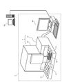
- FIG. 1 is a diagram showing the configuration of the entire system including the sample analyzer 1.
- the sample analyzer 1 according to the present embodiment includes a sample measurement device 2, a transport device 30, and an information processing device 40.
- the sample measurement apparatus 2 includes a first measurement unit 10 that performs a urine qualitative test and a second measurement unit 20 that performs a urine sediment test.
- the first measurement unit 10 and the second measurement unit 20 are connected so as to communicate with each other.
- the 1st measurement unit 10 and the 2nd measurement unit 20 are each connected so that communication with the information processing apparatus 40 is possible.
- the first measurement unit 10 is connected to the transfer device 30 so as to be communicable.
- the transport device 30 is a single unit common to the first measurement unit 10 and the second measurement unit 20.
- the transport device 30 is mounted on the front surface of the sample measuring device 2 and includes a transport path 31.
- the conveyance path 31 has a flat bottom surface that is one step lower than the upper surface of the conveyance device 30.
- the sample rack 50 transported on the transport path 31 is formed with ten holders so that ten sample containers 51 can be held.
- the sample container 51 is transported on the transport path 31 together with the sample rack 50 by being held in the holding portion of the sample rack 50.
- a barcode label (not shown) for specifying the sample is attached.
- the information processing apparatus 40 is communicably connected to the host computer 60 via a communication line.
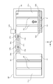
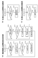
- FIG. 2 is a plan view showing a configuration when the transfer device 30 is viewed from above.
- the conveyance device 30 includes a conveyance path 31, transmission type sensors 32a and 32b, belts 33 and 38, an extrusion mechanism 34, lateral feed sensors 35a and 35b, and reflection type sensors 37a and 37b.
- the conveyance path 31 includes a right tank area 31a, a left tank area 31b, and a connection area 31c. The right tank area 31a and the left tank area 31b are connected by a connection area 31c.
- the transmission type sensors 32a and 32b include a light emitting unit and a light receiving unit, and detect the sample rack 50 positioned on the front side (end in the negative Y-axis direction) on the right tank region 31a. From the output signals of the sensors 32a and 32b, it is detected by the user that the sample rack 50 has been placed on the front side of the right tank region 31a.
- the belt 33 is installed in the right tank area 31a, moves the sample rack 50 placed in the right tank area 31a in the Y axis positive direction, and is positioned behind the right tank area 31a (the end in the Y axis positive direction). .
- the push-out mechanism 34 includes a drive unit (not shown) at the rear of the transport path 31, and pushes right and left (in the X-axis direction) from the right back of the right tank area 31a to the left back of the left tank area 31b.
- the nail is configured to move.
- FIG. 2 only the claw of the pushing mechanism 34 is shown.
- the push-out mechanism 34 pushes the right end side surface of the sample rack 50, the sample rack 50 positioned behind the right tank region 31a is moved to the rear of the left tank region 31b via the connection region 31c.
- the conveyance process of the sample rack 50 in the vicinity of the connection region 31c is appropriately performed according to the suction process of the first measurement unit 10 and the second measurement unit 20, as will be described later.
- the barcode reader 109 reads a sample number for identifying the sample container 51 from a barcode label attached to the sample container 51 positioned in the transport path 31 in front of the barcode reader 109 (Y-axis negative direction). .
- the barcode reader 109 is installed in the first measurement unit 10 and is directly controlled by the CPU 101a of the first measurement unit 10 (see FIG. 4).
- the lateral feed sensors 35a and 35b each have a claw projecting slightly upward (Z-axis positive direction) from the bottom surface of the conveyance path 31 (connection region 31c).
- the lateral feed sensors 35a and 35b are formed by the opening portion and the non-opening portion formed on the bottom surface of the sample rack 50 at intervals of the holding portion of the sample container 51.
- the claw changes into a state of protruding from the bottom surface of the conveyance path 31 and a state of not protruding. Thereby, it is appropriately determined whether or not the distance moved by the pushing mechanism 34 and the distance moved by the sample rack 50 are the same.
- the first supply position 36a and the second supply position 36b are positions where the sample stored in the sample container 51 is aspirated by the first measurement unit 10 and the second measurement unit 20, respectively.
- the nozzle 11 (see FIG. 3) provided in the first measurement unit 10 is inserted into the sample container 51 positioned at the first supply position 36a. At this time, the liquid level of the sample stored in the sample container 51 is detected. When it is determined that a predetermined amount or more of the sample is stored, the sample stored in the sample container 51 is aspirated by the nozzle 11. The aspirated specimen is measured in the first measurement unit 10. When the suction is completed, the nozzle 11 is extracted from the sample container 51, and the sample rack 50 holding the sample container 51 is moved leftward by the push-out mechanism 34. The liquid level detection of the specimen performed when the nozzle 11 is inserted into the specimen container 51 will be described later with reference to FIG.
- a nozzle (not shown) provided in the second measurement unit 20 is inserted into the sample container 51 positioned at the second supply position 36b. Subsequently, the sample stored in the sample container 51 is aspirated by the nozzle. The aspirated specimen is measured in the second measurement unit 20. When the suction is completed, the nozzle is extracted from the sample container 51, and the sample rack 50 holding the sample container 51 is moved leftward by the push-out mechanism 34.
- the distance between the first supply position 36a and the second supply position 36b is the same as the distance between the sample container 51 held in the holding portion at the left end (end in the positive X-axis direction) of the sample rack 50 and the right end (X in the figure). It is set to be equal to or less than the distance from the specimen container 51 held in the holding portion in the negative axial direction). Further, the first supply position 36a and the second supply position 36b are set so that the sample containers 51 held in two different holding units of one sample rack 50 are simultaneously positioned at the first supply position 36a and the second supply position 36b. And the interval is set. Thereby, the suction by the first measurement unit 10 and the suction by the second measurement unit 20 can be performed simultaneously.
- each of the reflective sensors 37a and 37b holds the sample container 51 in the holding portion of the sample rack 50 positioned in the transport path 31 in front of the reflective sensors 37a and 37b (Y-axis positive direction). Detect whether or not. Thereby, it is possible to confirm whether the sample container 51 whose sample number has been read by the barcode reader 109 is held in the holding unit of the corresponding sample rack 50 before aspiration again.
- the belt 38 is installed in the left tank region 31b, moves the sample rack 50 positioned behind the left tank region 31b (the end in the positive Y-axis direction) to the front, and before the left tank region 31b ( Position at the end in the negative Y-axis direction). In this way, the sample rack 50 positioned in front of the left tank region 31b is taken out by the user.
- FIG. 3 is a diagram for explaining the liquid level detection of the specimen that is performed when the nozzle 11 is inserted into the specimen container 51.
- FIGS. 4A and 4B are schematic views when a state in which the lower end of the nozzle 11 is aligned with the origin position and a state in which the lower end of the nozzle 11 is in contact with the liquid surface position are viewed from the side.
- FIG. 4A and 4B are schematic views when a state in which the lower end of the nozzle 11 is aligned with the origin position and a state in which the lower end of the nozzle 11 is in contact with the liquid surface position are viewed from the side.
- the nozzle 11 is made of a conductive metal member and is installed on the support 12.
- a pump (not shown) is connected to the nozzle 11, and the nozzle 11 can suck the sample by this pump.
- the support 12 is provided with a capacitive sensor 13 and a light shielding plate 14.
- the sensor 13 is connected to the nozzle 11.
- the support 12 is supported by a guide mechanism (not shown) so as to be movable in the vertical direction (Z-axis direction).
- the pulleys 15 a and 15 b, the belt 16, the stepping motor 106, the controller 107, and the sensor 17 are installed inside the first measurement unit 10.
- the pulleys 15a and 15b are installed so as to be rotatable about the Y axis.
- the belt 16 is stretched over pulleys 15a and 15b.
- the support body 12 is fixed to the belt 16, and the rotating shaft of the stepping motor 106 is connected to the pulley 15a.
- the stepping motor 106 is driven based on a pulse signal output from the controller 107.
- the controller 107 outputs pulse signals to the stepping motor 106 by the number of pulses specified by the CPU 101a (see FIG. 4) of the first measurement unit 10.
- the sensor 17 is a transmissive sensor composed of a light emitting part and a light receiving part. As shown in FIG. 3A, when the lower end of the nozzle 11 is aligned with the origin position, the light shielding plate 14 is positioned between the light emitting portion and the light receiving portion of the sensor 17.
- the stepping motor is arranged so that the light shielding plate 14 is positioned between the light emitting unit and the light receiving unit of the sensor 17. 106 is driven. As a result, the lower end of the nozzle 11 is positioned at the origin position as shown in FIG. From this state, the stepping motor 106 is driven so that the lower end of the nozzle 11 reaches the lower limit position.
- the lower limit position is a position slightly above the bottom surface of the sample container 51.
- the number of pulses designated by the CPU 101a to the controller 107 (hereinafter referred to as “specified pulse number”) in order for the lower end of the nozzle 11 to reach the lower limit position from the origin position is the storage unit 101b of the first measurement unit 10 in advance. (See FIG. 4).
- the nozzle 11 When the nozzle 11 is moved downward (Z-axis negative direction) and the lower end of the nozzle 11 is positioned at the liquid level as shown in FIG. 5B, the nozzle 11 is based on the output signal of the sensor 13. It is detected that the lower end of the liquid is in contact with the liquid surface.
- the descending width of the nozzle 11 at this time is the number of pulse signals output from the controller 107 to the stepping motor 106 until the lower end of the nozzle 11 reaches the liquid surface position (hereinafter referred to as “number of descending pulses”). Based on. Further, the sample amount is obtained based on a value obtained by subtracting the number of descending pulses from the number of prescribed pulses (hereinafter referred to as “number of remaining pulses”). In the sample measurement apparatus 2 of the present embodiment, since the sample container used has a predetermined shape and size, the relationship between the liquid level position and the sample amount is uniquely determined. Therefore, information on the sample amount can be obtained by using the number of descending pulses.
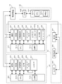
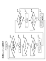
- FIG. 4 is a diagram showing the configuration of the first measurement unit 10, the second measurement unit 20, the transfer device 30, and the host computer 60.
- the first measurement unit 10 includes a control unit 101, a communication unit 102, a suction unit 103, a test paper supply unit 104, a detection unit 105, a stepping motor 106, a controller 107, a sensor unit 108, a barcode.
- a reader 109 is included.
- the control unit 101 includes a CPU 101a and a storage unit 101b.
- the CPU 101a executes the computer program stored in the storage unit 101b and controls each unit of the first measurement unit 10.
- the CPU 101 a controls each unit of the transport device 30 via the communication unit 102.
- the storage unit 101b includes storage means such as a ROM, a RAM, and a hard disk.
- the communication unit 102 processes a signal from the control unit 101 and outputs the signal to the second measurement unit 20, the transport device 30, and the information processing device 40, and the second measurement unit 20, the transport device 30, and the information.
- a signal from the processing device 40 is processed and output to the control unit 101.
- the suction unit 103 sucks the sample in the sample container 51 positioned at the first supply position 36 a through the nozzle 11 of the first measurement unit 10.
- the test paper supply unit 104 takes out the test paper necessary for the measurement from the test paper feeder in which the test paper is stored, and places the sample sucked by the suction unit 103 on the taken out test paper.
- the detection unit 105 measures the test paper on which the sample is spotted. The measurement result obtained by such measurement is output to the control unit 101 and analyzed by the CPU 101a.
- the stepping motor 106 is driven based on a pulse signal output from the controller 107.
- the controller 107 outputs a pulse signal from the CPU 101a to the stepping motor 106 by the designated number of pulses.
- the controller 107 has a memory 107a.
- the memory 107a stores the number of pulse signals output from the controller 107 to the stepping motor 106 and information indicating whether or not the number of pulses specified by the CPU 101a has been output to the stepping motor 106.
- the controller 107 updates the number of pulse signals stored in the memory 107a, and also indicates whether or not the pulse signal has been output by the designated number of pulses. Update.
- the sensor unit 108 includes the sensors 13 and 17 shown in FIG.
- the output signal of the sensor unit 108 and the sample number read by the barcode reader 109 are output to the control unit 101.
- the second measurement unit 20 includes a control unit 201, a communication unit 202, a suction unit 203, a sample preparation unit 204, a detection unit 205, a stepping motor 206, and a controller 207.
- the control unit 201 includes a CPU 201a and a storage unit 201b.
- the CPU 201a executes the computer program stored in the storage unit 201b and controls each unit of the second measurement unit 20.
- the storage unit 201b includes storage means such as a ROM, a RAM, and a hard disk.
- the communication unit 202 processes a signal from the control unit 201 and outputs the signal to the first measurement unit 10 and the information processing device 40, and processes a signal from the first measurement unit 10 and the information processing device 40 to control the signal.
- the suction unit 203 sucks the sample in the sample container 51 positioned at the second supply position 36b through the nozzle (not shown) of the second measurement unit 20.
- the sample preparation unit 204 mixes and stirs the sample aspirated by the aspiration unit 203 and a reagent necessary for measurement, and prepares a sample for measurement by the detection unit 205.
- the detection unit 205 measures the sample prepared by the sample preparation unit 204. A measurement result obtained by such measurement is output to the control unit 201.
- the stepping motor 206 is driven based on the pulse signal output from the controller 207, and moves the nozzle of the second measurement unit 20 in the vertical direction in the same manner as the stepping motor 106 of the first measurement unit 10.
- the controller 207 outputs a pulse signal to the stepping motor 206 by the number of pulses specified by the CPU 201a.
- the conveyance device 30 includes a communication unit 301, a conveyance driving unit 302, and a sensor unit 303.
- the communication unit 301 processes the signal from the first measurement unit 10 and outputs it to each part of the transport apparatus 30, and processes the signal from each part of the transport apparatus 30 and outputs it to the first measurement unit 10.
- the conveyance driving unit 302 is controlled by the CPU 101a of the first measurement unit 10.
- the transport driving unit 302 includes the belts 33 and 38 and the mechanism for driving the push-out mechanism 34 shown in FIG.
- the sensor unit 303 outputs output signals from various sensors to the first measurement unit 10 via the communication unit 301.
- the sensor unit 303 includes the sensors 32a and 32b, the lateral feed sensors 35a and 35b, and the sensors 37a and 37b shown in FIG.
- the host computer 60 includes a control unit 601 and a communication unit 602.
- the control unit 601 includes a CPU 601a and a storage unit 601b.
- the CPU 601a executes the computer program stored in the storage unit 601b, and returns an order stored in the storage unit 601b when an order inquiry is received from the information processing apparatus 40.
- the CPU 601a determines the order of the second measurement unit 20 based on the analysis result received from the first measurement unit 10 via the information processing device 40 and the measurement necessity reference stored in the storage unit 601b. decide.
- the storage unit 601b includes storage means such as a ROM, a RAM, and a hard disk.
- FIG. 5 is a diagram illustrating a circuit configuration of the information processing apparatus 40.
- the information processing apparatus 40 includes a personal computer, and includes a main body 400, an input unit 410, and a display unit 420.
- the main body 400 includes a CPU 401, a ROM 402, a RAM 403, a hard disk 404, a reading device 405, an input / output interface 406, an image output interface 407, and a communication interface 408.
- the CPU 401 executes a computer program stored in the ROM 402 and a computer program loaded in the RAM 403.
- the CPU 401 makes an order inquiry to the host computer 60 based on the order inquiry received from the first measurement unit 10 and the second measurement unit 20. Further, the CPU 401 transmits the order received from the host computer 60 to the first measurement unit 10 and the second measurement unit 20.
- the RAM 403 is used to read out computer programs recorded in the ROM 402 and the hard disk 404.
- the RAM 403 is also used as a work area for the CPU 401 when executing these computer programs.
- the hard disk 404 is installed with various computer programs to be executed by the CPU 401 such as an operating system and application programs, and data used for executing the computer programs. Further, the hard disk 404 analyzes a program for displaying on the display unit 420 based on the analysis result transmitted from the first measurement unit 10 or the measurement result transmitted from the second measurement unit 20, and the analysis result A program or the like for performing display on the display unit 420 based on the above is installed.
- the hard disk 404 is installed with a program for displaying the specimen shortage notification screen 700 (see FIG. 9B), a program for displaying the processing setting screen 800 (see FIG. 12), and the like.
- the reading device 405 is configured by a CD drive, a DVD drive, or the like, and can read a computer program and data recorded on a recording medium.
- An input unit 410 such as a mouse or a keyboard is connected to the input / output interface 406, and data is input to the information processing apparatus 40 when the user uses the input unit 410.
- the image output interface 407 is connected to a display unit 420 configured with a display or the like, and outputs a video signal corresponding to the image data to the display unit 420.
- the display unit 420 displays an image based on the input video signal.
- the communication interface 408 enables data transmission / reception to / from the first measurement unit 10, the second measurement unit 20, and the host computer 60.
- FIG. 6 is a flowchart showing the conveyance process of the first measurement unit 10.
- the CPU 101a of the first measurement unit 10 waits for processing until receiving a measurement start instruction from the information processing apparatus 40 (S101).
- the measurement start instruction is transmitted from the information processing apparatus 40 to the first measurement unit 10 when an instruction to start measurement is input by the user via the input unit 410 of the information processing apparatus 40.
- the CPU 101a waits for the process until the sample rack 50 is set in front of the right tank region 31a of the transport device 30.
- the CPU 101a sends the sample rack 50 to the rear of the right tank area 31a (S103).
- the CPU 101a waits for the process until the suction process currently performed by the first measurement unit 10 is completed (S104). That is, the CPU 101a waits for processing until the nozzle 11 is extracted from the sample container 51 and the sample rack 50 that holds the sample container 51 that stores the sample becomes movable. After the sample rack 50 is sent to the rear of the right tank region 31a in S103, the determination in S104 is performed until the suction processing for the first (leftmost) sample container 51 held in the sample rack 50 is started. Is set to YES.
- the CPU 101a waits for processing until the command most recently received from the second measurement unit 20 indicates that the command can be conveyed (S105).
- the command transmitted from the second measurement unit 20 will be described later with reference to FIG.
- the CPU 101a drives the push-out mechanism 34 to move the sample rack 50 by a predetermined distance (one pitch). That is, the sample rack 50 is conveyed leftward (X-axis positive direction) by a distance corresponding to the interval between the holding portions of the sample rack 50 (S106).
- the barcode reader 109 reads the sample number from the barcode label attached to the sample container 51.
- the CPU 101 a acquires from the drive amount of the push-out mechanism 34 which holding unit of the sample rack 50 holds the sample container 51 whose sample number has been read. Further, the CPU 101a inquires the information processing apparatus 40 about the order of the first measurement unit 10 based on the read sample number. Thereafter, the CPU 101a receives the order of the first measurement unit 10 from the information processing apparatus 40.
- the aspiration processing is performed on the sample stored in the positioned sample container 51, respectively.
- the sample container 51 is simultaneously positioned at the first supply position 36a and the second supply position 36b, the samples stored in the sample containers 51 positioned at the respective positions can be aspirated simultaneously. .
- the CPU 101a first determines whether the sample container 51 is positioned at the first supply position 36a (S107). When the sample container 51 is positioned at the first supply position 36a (S107: YES), the CPU 101a starts the suction process by the first measurement unit 10 (S108). On the other hand, if the sample container 51 is not positioned at the first supply position 36a (S107: NO), the process proceeds to S109.
- the suction processing by the first measurement unit 10 will be described later with reference to FIG.
- the CPU 101a determines whether the sample container 51 is positioned at the second supply position 36b (S109).
- the CPU 101a transmits a suction instruction to the second measurement unit 20 (S110), and the process returns to S104.
- the process proceeds to S111.
- the aspiration instruction includes the sample number of the sample container 51 positioned at the second supply position 36b.
- the CPU 101a stores the sample rack 50 in the storage position (front of the left tank region 31b). (S112), and the process proceeds to S113. On the other hand, if the sample rack 50 is not transported to the left rear (S111: NO), the process returns to S104.
- the CPU 101a determines whether a measurement stop instruction is received from the information processing apparatus 40.
- the measurement stop instruction is transmitted from the information processing apparatus 40 to the first measurement unit 10 when an instruction to stop the measurement is input by the user via the input unit 410 of the information processing apparatus 40.
- the CPU 101a receives the measurement stop instruction (S113: YES)
- the process returns to S101.
- the CPU 101a has not received the measurement stop instruction (S113: NO)
- the process returns to S102. In this way, the processing of S101 to S113 is repeated.
- FIG. 7 is a flowchart showing the suction process by the first measurement unit 10.
- the CPU 101a of the first measurement unit 10 first adjusts the nozzle 11 to the origin position as described with reference to FIG. 3 (S201). Subsequently, the CPU 101a lowers the nozzle 11 (S202). Specifically, the CPU 101a outputs a specified number of pulses to the controller 107. After resetting the number of pulse signals stored in the memory 107a, the controller 107 continues to output pulse signals to the stepping motor 106 until the number of pulse signals output to the stepping motor 106 reaches the specified number of pulses. Thereby, the lower end of the nozzle 11 is gradually moved downward from the origin position toward the lower limit position.
- the CPU 101a determines whether the liquid level of the specimen is detected based on the output signal of the sensor 13 (S203).
- the CPU 101a stops the driving of the stepping motor 106 via the controller 107 even if the lowering amount of the nozzle 11 does not reach the specified pulse.
- the movement of the nozzle 11 is stopped (S204).
- the CPU 101a refers to the memory 107a and acquires the number of falling pulses (S205).
- the CPU 101a refers to the memory 107a, and the number of descending pulses is based on the information indicating whether or not the pulse signal is transmitted to the stepping motor 106 by the designated number of pulses. It is determined whether has reached the specified number of pulses (S206).
- the CPU 101a obtains the remaining pulse number by subtracting the falling pulse number obtained in S205 from the specified pulse number, and determines whether the remaining pulse number is equal to or greater than the threshold value P (S207). If YES is determined in S206, the remaining number of pulses is set to 0, and NO is determined in S207.
- the threshold value P is determined according to the amount of sample required when measurement is performed in both the first measurement unit 10 and the second measurement unit 20.
- the threshold value P is a pulse that is necessary for moving the nozzle 11 by the height of the liquid surface position that decreases when suctioned by both the first measurement unit 10 and the second measurement unit 20.
- the number of pulses P2 is determined according to the dead volume necessary to enable the first measurement unit 10 and the second measurement unit 20 to be sucked.
- the number of pulses P2 may be a value obtained by further adding a predetermined value to the value determined according to the dead volume so that the suction of the first measurement unit 10 and the second measurement unit 20 is more reliably performed. .
- the CPU 101a sends information indicating that a sufficient amount of sample is stored in the sample container 51 (hereinafter referred to as “sample sufficient information”) to the information processing apparatus. 40 (S208). Subsequently, the CPU 101a lowers the nozzle 11 below the liquid level by a predetermined number of pulses, sucks the sample from the sample container 51, and raises the nozzle 11 when the suction is completed (S209). Note that the CPU 101a determines whether measurement is necessary based on the order received from the information processing apparatus 40 before the sample is aspirated. Further, when the sample is aspirated, the CPU 101a performs measurement based on the order. Further, the CPU 101 a analyzes the measurement result and transmits the analysis result to the information processing apparatus 40.
- the CPU 101a transmits an order inquiry instruction to the second measurement unit 20 (S210), and the aspiration processing for this sample is completed.
- the order inquiry instruction includes the sample number of the sample container 51 that is the subject of this aspiration processing.
- the CPU 101a determines which of the processes A to C is set as the process to be executed when the sample is insufficient (S211 and S213). Note that the processing setting when the sample is insufficient is stored in the storage unit 101b of the first measurement unit 10 and the hard disk 404 of the information processing apparatus 40, as will be described later.
- processing A is performed (S212). If the processing setting at the time of sample shortage is processing B (S211: NO, S213: YES), “processing B” is performed (S214). If the processing setting at the time of sample shortage is processing C (S211: NO, S213: NO), “processing C” is performed (S215). “Process A”, “Process B”, and “Process C” will be described later with reference to FIG.
- FIG. 8A is a flowchart showing “Process A”.
- the CPU 101a of the first measurement unit 10 transmits information indicating that a sufficient amount of samples are not stored in the sample container 51 (hereinafter referred to as “sample shortage information”) to the information processing apparatus 40 (S301).
- the sample amount shortage information includes the sample number of the sample container 51 and information indicating in which holding unit on the sample rack 50 the sample container 51 is held. Subsequently, the CPU 101a raises the nozzle 11 without sucking the sample in the sample container 51 (S302).
- the CPU 101a determines whether or not there is a sample that has been aspirated by the first measurement unit 10 and has not yet been aspirated by the second measurement unit 20 on the sample rack 50 positioned directly below the nozzle 11. (S303).
- the CPU 101a waits for processing until the command most recently received from the second measurement unit 20 indicates that it can be conveyed (S304).
- the CPU 101a drives the push-out mechanism 34 to complete the suction by the first measurement unit 10.
- the first (leftmost) sample is transported to the second supply position 36b (S305).
- the CPU 101a transmits a suction instruction to the second measurement unit 20 as in S110 of FIG. 6 (S306), and the process returns to S303.
- the CPU 101a waits for processing until the command most recently received from the second measurement unit 20 indicates that it can be conveyed (S307). If it is determined that the command most recently received from the second measurement unit 20 indicates that it can be transported (S307: YES), the CPU 101a transports the sample rack 50 to the storage position (in front of the left tank region 31b) (S308). .
- FIG. 8B is a flowchart showing “Process B” and “Process C”.
- the CPU 101a of the first measurement unit 10 transmits the sample shortage information to the information processing apparatus 40 (S311). Subsequently, the CPU 101a raises the nozzle 11 without sucking the sample (S312).
- the first measurement unit 10 does not perform aspiration on the sample with the insufficient sample amount positioned at the first supply position 36a.
- the aspiration processing by the first measurement unit 10 and the second measurement unit 20 is performed on the sample behind (right side) the sample.
- a sample that is forward (left side) of this sample and that has already been aspirated by the first measurement unit 10 is the same as “Process A”.
- a suction process by the measurement unit 20 is performed.
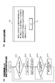
- FIG. 9A is a flowchart showing the display process of the specimen shortage notification screen by the information processing apparatus 40.
- the CPU 401 of the information processing apparatus 40 receives the sample shortage information transmitted from the first measurement unit 10 in S301 of FIG. 8A and S311 of FIG. 8B (S401: YES), the received sample shortage The information is stored in the hard disk 404 (S402), and the sample shortage notification screen 700 is displayed on the display unit 420 (S403).
- FIG. 9B is an exemplary diagram of a sample shortage notification screen 700 displayed on the display unit 420 of the information processing apparatus 40.
- the sample shortage notification screen 700 indicates that there is a sample container 51 that does not contain a sample amount necessary for performing measurement in both the first measurement unit 10 and the second measurement unit 20.
- a message is displayed. This message also indicates which holding unit on the sample rack 50 holds the sample container 51 that does not contain the required sample amount. As a result, the user can know that the sample container 51 that does not contain the required amount of sample has been detected, and which holding unit of the sample rack 50 holds the sample container 51.
- the specimen shortage notification screen 700 includes an OK button 701. The user can close the sample shortage notification screen 700 by pressing an OK button 701.
- the CPU 401 stores the received sample satisfaction information in the hard disk 404 even when the sample satisfaction information transmitted from the first measurement unit 10 is received in S208 of FIG.
- FIG. 10 is a flowchart showing the suction process by the second measurement unit 20.
- the CPU 201a of the second measurement unit 20 waits for processing until an order inquiry instruction is received from the first measurement unit 10 (S501).
- the CPU 201a inquires the information processing apparatus 40 about the order of the second measurement unit 20 for the specimen based on the specimen number included in the order inquiry instruction (S502).
- the CPU 201a waits for processing until an order is received from the information processing apparatus 40 (S503).
- the CPU 201a receives the order (S503: YES)
- the CPU 201a waits for the process until a suction instruction is received from the first measurement unit 10 (S504).
- the order received from the information processing apparatus 40 includes information on whether or not the second measurement unit 20 performs suction.
- the CPU 201a When the CPU 201a receives the suction instruction (S504: YES), the CPU 201a writes a command indicating that the conveyance is impossible to the buffer in the storage unit 201b of the second measurement unit 20 (S505). In the buffer in the storage unit 201b, either a command indicating that conveyance is possible or a command indicating that conveyance is not possible is written, and a command indicating that conveyance is possible is written as an initial value. The command written in the buffer in the storage unit 201b is transmitted to the first measurement unit 10 every predetermined time.
- the CPU 201a determines whether or not to aspirate the sample positioned at the second supply position 36b based on the order received in S503 (S506). If it is determined that the sample is to be aspirated (S506: YES), the CPU 201a aspirates the sample from the sample container 51 by the nozzle of the second measurement unit 20, and raises the nozzle when the aspiration is completed (S507). The CPU 201a performs measurement based on the order when the sample is aspirated. In addition, the CPU 201 a transmits the measurement result to the information processing apparatus 40. On the other hand, if it is determined that the sample is not aspirated (S506: NO), the CPU 201a advances the process to S509.
- the CPU 201a waits for the process until the aspiration by the second measurement unit 20 is completed (S508). That is, the CPU 201a waits for processing until the nozzle of the second measurement unit 20 is extracted from the sample container 51 and the sample rack 50 holding the sample container 51 that accommodates the sample becomes movable.
- the CPU 201a writes a command indicating that conveyance is possible in the buffer in the storage unit 201b of the second measurement unit 20 (S509). In this way, the processing of S501 to S509 is repeatedly performed.
- FIG. 11 is a flowchart showing order processing by the information processing apparatus 40.
- the CPU 401 of the information processing apparatus 40 When the CPU 401 of the information processing apparatus 40 receives an order inquiry from the second measurement unit 20 (S601: YES), it makes an order inquiry to the host computer 60 (S602). The CPU 401 waits for processing until the order inquired in S602 is received from the host computer 60 (S603).
- the CPU 401 determines whether the sample stored in the sample container 51 that is the source of this order is insufficient in sample amount (S604). This determination is performed based on the sample satisfaction information (S208 in FIG. 7) or the sample shortage information (S301 in FIG. 8A and S311 in FIG. 8B) transmitted from the first measurement unit 10.
- the CPU 201a transmits the order of the sample including the aspiration to the second measurement unit 20 (S605). On the other hand, if the sample amount is insufficient (S604: YES), the CPU 201a determines whether the process to be executed when the sample amount is insufficient is set to process B (S606). If the processing setting at the time of the sample shortage is the processing B (S606: YES), the processing proceeds to S605, and an order including that suction is performed is transmitted to the second measurement unit 20. On the other hand, if the processing setting at the time of the sample shortage is not the processing B (S606: NO), the CPU 201a transmits to the second measurement unit 20 that the aspiration is not performed as an order of this sample (S607).
- the process setting screen 800 includes radio buttons 801a, 801b, and 801c, an OK button 802a, and a cancel button 802b.
- Radio buttons 801a to 801c are selected when pressed by the user. Radio buttons 801a to 801c correspond to processing A to processing C, and only one is selected. In addition, on the right side of the radio buttons 801a to 801c, outlines of processing contents for processing A to processing C are shown, respectively.
- the processing when the sample is insufficient is changed according to the selection state of the radio buttons 801a to 801c, and the processing setting screen 800 is closed. If the user presses the cancel button 802b, the processing when the sample is insufficient is not changed, and the processing setting screen 800 is closed.
- process A is set as a default. Therefore, if the setting is not changed by the user, “Process A” is executed, and neither the first measurement unit 10 nor the second measurement unit 20 performs aspiration and measurement for a sample with insufficient sample amount.
- FIG. 13A is a flowchart showing the display processing of the processing setting screen 800 by the information processing apparatus 40.
- the CPU 401 of the information processing apparatus 40 determines whether a display instruction for the processing setting screen 800 has been received (S701). Note that a display instruction for the processing setting screen 800 is given by the user via the input unit 410 of the information processing apparatus 40.
- the CPU 401 receives an instruction to display the process setting screen 800 (S701: YES)
- the CPU 401 inquires of the first measurement unit 10 about the process setting (S702).
- the CPU 401 waits for processing until it receives processing settings from the first measurement unit 10 (S703).
- the CPU 401 stores the received process setting in the hard disk 404 (S704).
- the CPU 401 displays the process setting screen 800 on the display unit 420, and selects any one of the radio buttons 801a to 801c based on the received process setting (S705).
- the CPU 401 stores the processing setting in the hard disk 404 according to the selection state of the radio buttons 801a to 801c (S708). In addition, the CPU 401 transmits the processing settings stored in the hard disk 404 to the first measurement unit 10 (S709).
- the OK button 802a is not pressed, that is, if the cancel button 802b is pressed (S707: NO)
- the process proceeds to S710.
- step S710 the CPU 401 hides the processing setting screen 800. In this way, the processing of S701 to S710 is repeated.
- FIG. 13B is a flowchart showing processing setting transmission processing by the first measurement unit 10.
- the CPU 101a of the first measurement unit 10 receives a processing setting inquiry from the information processing apparatus 40 (S801: YES), and stores it in the information processing apparatus 40 in the storage unit 101b.
- the processing setting being performed is transmitted (S802).
- FIG. 13C is a flowchart showing a process setting reception process by the first measurement unit 10.
- the CPU 101a of the first measurement unit 10 receives the processing setting from the information processing apparatus 40 (S811: YES), and stores the received processing setting in the storage unit 101b (S812). ).
- the remaining number of pulses is smaller than the threshold value P (S207 of FIG. 7: NO). That is, when the amount of the sample in the sample container 51 is less than the amount necessary for performing the measurement in both the first measurement unit 10 and the second measurement unit 20, Even in the measurement unit, the sample is not aspirated from the sample container 51. Thereby, before the sample is aspirated by the first measurement unit 10 and the second measurement unit 20, the user can select an appropriate method. Therefore, it is possible to prevent the occurrence of a situation where the specimen is reacquired from the patient.
- the appropriate method is, for example, that one of the first measurement unit 10 and the second measurement unit 20 is automatically analyzed by the measurement unit, and the other analysis is a method used instead of the automatic analysis.
- the method of performing is mentioned. Specifically, the first measurement for urine qualitative analysis is performed when the user does not have sufficient sample amount for both analyzes in the first measurement unit 10 and the second measurement unit 20 but is sufficient for one analysis. It is conceivable that the analysis is performed by a method instead of the analysis in the unit 10 and the analysis in the second measurement unit 20 for urine sediment analysis is desired to be automatically performed by the unit.
- the process B is set by the user, only the suction by the second measurement unit 20 can be performed. Accordingly, the user can appropriately perform the suction by the second measurement unit 20 over the first measurement unit 10 as appropriate.
- the process C is set by the user, the first measurement unit is normally used for the sample behind the sample whose sample amount is insufficient. Aspiration and measurement by 10 and the second measurement unit 20 can be performed. In this case, since it is not necessary to set the rear sample container in the transport apparatus 30 again, the burden on the user can be reduced.
- the sample shortage notification screen 700 shown in FIG. 9B is displayed on the display unit 420, so that the user has a sample whose sample amount is insufficient. It is possible to easily recognize which holding unit of the sample rack 50 holds the sample.
- the processing setting at the time of sample shortage can be changed via the processing setting screen 800 shown in FIG. Can be processed.
- the processing when the sample amount is insufficient can be selected and set from “Processing A”, “Processing B”, and “Processing C” as appropriate. it can.
- urine is exemplified as a measurement target, but blood can also be a measurement target. That is, the present invention can be applied to a sample analyzer that tests blood, and further, the present invention can be applied to a clinical sample analyzer that tests other clinical samples.
- the sample shortage notification screen 700 is displayed on the display unit 420 of the information processing apparatus 40.
- the display unit 420 is not limited thereto.
- the color of a part of the display content may be changed, or an alarm installed in the sample measuring device 2 may be sounded.
- the alarm When the alarm is set, the alarm may be sounded only when the processing setting when the sample is insufficient is the process A.
- the sample amount in the sample container 51 is detected by the number of pulses supplied to the stepping motor 106, but the sample amount may be detected by other methods.
- the amount of sample in the sample container 51 is detected based on the time required for the nozzle 11 to reach the liquid level of the sample from the origin position and the size of the capacitance at the tip of the nozzle 11 when detecting the liquid level. You can also.
- the liquid level position may be detected by light or ultrasonic waves, or an image of a sample container may be captured and analyzed to detect the liquid level position and detect the sample amount.
- the sample amount may be detected based on the weight of the sample.
Abstract
Provided is a specimen analysis device that enables the accurate performance of multiple types of measurement without reacquiring a specimen. A first measurement unit (10) draws up a specimen from a specimen container (51) using a nozzle (11) and takes measurements. The nozzle (11) connects to an electrostatic capacitance-type sensor (13) for detecting liquid level. A conveyor device (30) conveys the specimen container (51) from the first measurement unit (10) to a second measurement unit (20). When the amount of specimen in the specimen container (51), which is acquired on the basis of the sensor (13), is less than the amount of specimen necessary for the performance of measurements in both the first measurement unit (10) and the second measurement unit (20), the specimen is not drawn into any of the measurement units. Therefore, before the specimen is drawn up by the first measurement unit (10) or the second measurement unit (20), a user can select appropriate methods and obtain measurement results from both. Consequently, the specimen does not need to be reacquired.
Description
本発明は、種類の異なる複数の測定ユニットを搬送装置で接続した検体分析装置に関する。
The present invention relates to a sample analyzer in which a plurality of different types of measurement units are connected by a transport device.
検体を吸引する前にセンサにより液量を検知し、検知した液量が検体の分析に必要な液量に足りない場合に、検体の吸引を中止する分析装置が知られている(例えば、特許文献1参照)。
There is known an analyzer that detects the amount of liquid with a sensor before aspirating the specimen, and stops the aspiration of the specimen when the detected liquid quantity is insufficient for the amount of liquid necessary for the analysis of the specimen (for example, a patent Reference 1).
また、近年、互いに種類の異なる複数の測定ユニットを搬送装置で接続した分析装置が販売されている。このような分析装置の測定ユニットには、それぞれ吸引管が設けられており、検体容器は上流側の測定ユニットから下流側の測定ユニットに順次搬送され、それぞれの吸引管により検体が吸引される。
In recent years, analyzers in which a plurality of different types of measurement units are connected by a transport device have been sold. Each measurement unit of such an analyzer is provided with a suction tube, and the sample container is sequentially transported from the upstream measurement unit to the downstream measurement unit, and the sample is sucked through the respective suction tubes.
しかしながら、上記のように接続された複数の測定ユニットの各々に、特許文献1に記載のような液量確認機能付きの分析装置を適用すると、検体の液量が最上流の測定ユニットの測定には足りるが下流の測定ユニットの測定には不足する場合には、最上流の測定ユニットにより検体が吸引され、残った微量の検体が下流の測定ユニットに搬送される。この場合、下流の測定ユニットによる測定が行えず、結局、検体の再取得が必要になってしまう可能性がある。
However, when an analyzer with a liquid volume confirmation function as described in Patent Document 1 is applied to each of the plurality of measurement units connected as described above, the liquid volume of the specimen is used for the measurement of the most upstream measurement unit. However, if the measurement is insufficient for the measurement of the downstream measurement unit, the sample is aspirated by the most upstream measurement unit, and the remaining trace amount of the sample is transported to the downstream measurement unit. In this case, measurement by the downstream measurement unit cannot be performed, and it may be necessary to reacquire the sample after all.
本発明は、かかる課題に鑑みてなされたものであり、検体の再取得をせずに、検体を有効に活用することを可能とする検体分析装置を提供することを目的とする。
The present invention has been made in view of such problems, and an object of the present invention is to provide a sample analyzer that can effectively use a sample without reacquiring the sample.
本発明の主たる態様は、検体分析装置に関する。この態様に係る検体分析装置は、検体容器中の検体を吸引して第1の測定を実行する第1測定ユニットと、前記検体容器中の検体を吸引して前記第1測定ユニットとは異なる第2の測定を実行する第2測定ユニットと、前記検体容器を前記第1測定ユニットから前記第2測定ユニットの順に搬送する搬送装置と、前記第1測定ユニットが前記検体容器中の検体を吸引する前の当該検体容器中の検体量に関する情報を検出する検出部と、前記検出部の検出結果と、前記第1測定ユニットおよび前記第2測定ユニットの両方で測定を実行する場合に必要となる所定の検体量に関する情報と、に基づき、前記検体容器中の検体量が前記所定の検体量に足りるか否か判定し、足りないと判定した場合には、前記第1測定ユニットおよび前記第2測定ユニットのいずれも前記検体容器中の検体を吸引しないよう、前記第1測定ユニット、前記第2測定ユニット、および前記搬送装置を制御する制御部と、を備える。
The main aspect of the present invention relates to a sample analyzer. The sample analyzer according to this aspect includes a first measurement unit that sucks a sample in a sample container and executes a first measurement, and a first measurement unit that sucks a sample in the sample container and is different from the first measurement unit. A second measurement unit that performs the measurement of 2, a transport device that transports the sample container in order from the first measurement unit to the second measurement unit, and the first measurement unit aspirates the sample in the sample container A detection unit that detects information related to the amount of the sample in the previous sample container, a detection result of the detection unit, and a predetermined necessary when measurement is performed by both the first measurement unit and the second measurement unit. And determining whether the sample amount in the sample container is sufficient for the predetermined sample amount, and if it is determined that the sample amount is not sufficient, the first measurement unit and the second measurement unit Yu As none of Tsu bets not sucks the specimen in the specimen container, and a control unit for controlling the first measuring unit, the second measuring unit, and the transport device.
ここで、「検体量に関する情報」とは、検体を吸引するためのノズルが基準位置から検体の液面に到達するまでのノズルの下降量(たとえば、ノズルがステッピングモータにて駆動される場合には、ステッピングモータに供給された駆動パルス数)や、ノズルが基準位置から検体の液面に到達するまでに要した時間、液面検知時におけるノズル先端部における静電容量の大きさ等、検体量に応じて変化する情報を広く含む。検体量は、上記以外に、光、超音波、画像解析、検体の重量等によっても検出可能であり、上記「検体量に関する情報」は、これら他の方法により取得される値や情報をも含むものである。
Here, the “information about the sample amount” means the amount of nozzle lowering until the nozzle for sucking the sample reaches the liquid level of the sample from the reference position (for example, when the nozzle is driven by a stepping motor). Is the number of drive pulses supplied to the stepping motor), the time required for the nozzle to reach the liquid level of the specimen from the reference position, the magnitude of the capacitance at the nozzle tip when the liquid level is detected, etc. Includes a wide range of information that varies with quantity. In addition to the above, the sample amount can also be detected by light, ultrasound, image analysis, sample weight, etc., and the above “information on sample amount” includes values and information obtained by these other methods. It is a waste.
本態様に係る検体分析装置によれば、第1測定ユニットおよび第2測定ユニットの両方で測定を実行するには検体容器中の検体が足りない場合には、いずれの測定ユニットにおいても当該検体容器から検体は吸引されない。こうすると、第1測定ユニットと第2測定ユニットによって検体が吸引されてしまう前に、ユーザは、適切な方法(たとえば、いずれか一方または両方の測定ユニットによる測定を、用手法に切り替え、あるいは、希釈検体を用いた測定とする、など)を選択することができる。よって、検体を患者から再取得するような事態の発生を防ぐことができる。
According to the sample analyzer according to this aspect, when there are not enough samples in the sample container to perform measurement in both the first measurement unit and the second measurement unit, the sample container is used in any measurement unit. The sample is not aspirated. In this way, before the sample is aspirated by the first measurement unit and the second measurement unit, the user can switch the measurement by an appropriate method (for example, measurement by one or both measurement units to the method used, or The measurement using a diluted specimen can be selected. Therefore, it is possible to prevent the occurrence of a situation where the specimen is reacquired from the patient.
本態様に係る検体分析装置において、前記制御部が、前記検体容器中の検体量が前記所定の検体量に足りないと判定した場合、当該検体容器より搬送方向後方の検体容器中の検体について検体量に関する情報を前記検出部によって検出し、前記制御部は、前記検出部の検出結果に応じて前記第1測定ユニット、前記第2測定ユニット、および前記搬送装置を制御するよう構成され得る。こうすると、後方の検体容器に対する吸引および測定が中断されないため、ユーザの負担を軽減することができる。
In the sample analyzer according to this aspect, when the control unit determines that the amount of the sample in the sample container is not sufficient for the predetermined sample amount, the sample is detected for the sample in the sample container behind the sample container in the transport direction. Information relating to the amount may be detected by the detection unit, and the control unit may be configured to control the first measurement unit, the second measurement unit, and the transport device according to a detection result of the detection unit. In this way, the suction and measurement for the rear specimen container are not interrupted, and the burden on the user can be reduced.
または、本態様に係る検体分析装置において、前記制御部は、前記検体容器中の検体量が、前記所定の検体量に足りないと判定した場合、当該検体容器より搬送方向後方の検体容器中の検体については、前記第1測定ユニットおよび前記第2測定ユニットによる吸引処理を中止するよう、前記第1測定ユニット、前記第2測定ユニット、および前記搬送装置を制御するよう構成され得る。こうすると検体量が足りないと判定された検体について、迅速に、適切な対応を行うことができる。
Alternatively, in the sample analyzer according to this aspect, when the control unit determines that the sample amount in the sample container is not sufficient for the predetermined sample amount, the control unit For the sample, the first measurement unit, the second measurement unit, and the transport device may be controlled to stop the aspiration processing by the first measurement unit and the second measurement unit. In this way, it is possible to promptly and appropriately deal with a sample determined to have insufficient sample amount.
この場合に、前記制御部は、前記検体容器中の検体量が、前記所定の検体量に足りないと判定した場合、その時点で既に前記第1測定ユニットによって吸引された検体については、前記第2測定ユニットによる吸引処理を継続するよう、前記第2測定ユニットおよび前記搬送装置を制御するよう構成され得る。こうすると、第1測定ユニットによって吸引済みの検体を、第2測定ユニットでの測定のために再度搬送装置にセットする必要がない。よって、検体量が足りないと判定された検体について迅速に処理を開始しつつ、ユーザの負担を軽減することができる。
In this case, when the control unit determines that the sample amount in the sample container is not sufficient for the predetermined sample amount, the sample already sucked by the first measurement unit at that time is used for the first measurement unit. It may be configured to control the second measurement unit and the transport device so as to continue the suction process by the two measurement units. In this way, there is no need to set the sample that has been aspirated by the first measurement unit to the transport device again for measurement by the second measurement unit. Therefore, it is possible to reduce the burden on the user while quickly starting the processing for the sample determined to be insufficient.
また、本態様に係る検体分析装置は、前記検体容器中の検体量が、前記所定の検体量に足りない場合の処理を、複数の設定から選択する設定選択手段を、さらに備えるよう構成され得る。こうすると、ユーザの要望に応じた処理が可能となる。
In addition, the sample analyzer according to this aspect may be configured to further include setting selection means for selecting a process when the sample amount in the sample container is insufficient for the predetermined sample amount from a plurality of settings. . In this way, processing according to the user's request becomes possible.
この場合に、前記複数の設定は、前記検体容器中の検体量が、前記所定の検体量に足りないと判定された場合、当該検体容器より搬送方向後方の検体容器中の検体については、前記第1測定ユニットおよび前記第2測定ユニットによる吸引処理を継続する第1設定と、前記検体容器中の検体量が、前記所定の検体量に足りないと判定された場合、当該検体容器より搬送方向後方の検体容器中の検体については、前記第1測定ユニットおよび前記第2測定ユニットによる吸引処理を中止する第2設定と、を含むよう構成され得る。
In this case, the plurality of settings are as follows: when it is determined that the amount of the sample in the sample container is not sufficient for the predetermined sample amount, the sample in the sample container at the rear in the transport direction from the sample container The first setting for continuing the aspiration processing by the first measurement unit and the second measurement unit, and when it is determined that the sample amount in the sample container is insufficient for the predetermined sample amount, the transport direction from the sample container The sample in the rear sample container may be configured to include a second setting for stopping the suction processing by the first measurement unit and the second measurement unit.
さらに、前記複数の設定は、前記所定の検体量に足りないと判定された検体について、前記第1測定ユニットおよび前記第2測定ユニットの何れか一方では測定のための処理を行う第3設定を含むよう構成され得る。
Further, the plurality of settings may include a third setting for performing a measurement process on one of the first measurement unit and the second measurement unit for a sample determined to be insufficient for the predetermined sample amount. May be configured to include.
また、本態様に係る検体分析装置は、前記検体容器中の検体量が、前記所定の検体量に足りない場合に、その旨を通知する通知手段を、さらに備えるよう構成され得る。こうすると、ユーザは、検体量が不足している検体の存在を容易に認識することができる。
In addition, the sample analyzer according to this aspect may be configured to further include notification means for notifying that when the sample amount in the sample container is insufficient for the predetermined sample amount. In this way, the user can easily recognize the presence of a sample whose sample amount is insufficient.
また、本態様に係る検体分析装置において、前記第1測定ユニットは尿定性測定ユニットであり、前記第2測定ユニットは尿沈渣測定ユニットであるよう構成され得る。
In the sample analyzer according to this aspect, the first measurement unit may be a urine qualitative measurement unit, and the second measurement unit may be a urine sediment measurement unit.
以上のとおり、本発明によれば、検体の再取得をせずに、検体を有効に活用することを可能とする検体分析装置を提供することができる。
As described above, according to the present invention, it is possible to provide a sample analyzer that enables effective use of a sample without reacquiring the sample.
本発明の効果ないし意義は、以下に示す実施の形態の説明により更に明らかとなろう。ただし、以下に示す実施の形態は、あくまでも、本発明を実施化する際の一つの例示であって、本発明は、以下の実施の形態により何ら制限されるものではない。
The effect or significance of the present invention will become more apparent from the following description of embodiments. However, the embodiment described below is merely an example when the present invention is implemented, and the present invention is not limited to the following embodiment.
ただし、図面はもっぱら説明のためのものであって、この発明の範囲を限定するものではない。
However, the drawings are for explanation only and do not limit the scope of the present invention.
本実施の形態は、尿蛋白、尿糖等の検査(尿定性の検査)、および、尿中に含まれる赤血球、白血球、上皮細胞等の検査(尿沈渣の検査)を行う臨床検体分析装置に本発明を適用したものである。尿沈渣の検査は、尿定性の検査が行われた結果、さらに尿沈渣の検査が必要であるとされた検体について行われる。本実施の形態では、異なる検体を収容する複数の検体容器がラックにセットされ、このラックが検体分析装置にセットされて各検体の検査が行われる。
The present embodiment is a clinical sample analyzer that performs tests for urine protein, urine sugar, etc. (urine qualitative test) and tests for red blood cells, white blood cells, epithelial cells, etc. contained in urine (test for urine sediment). The present invention is applied. The examination of the urine sediment is performed on a specimen that is further required to be examined for urine sediment as a result of the qualitative examination of urine. In the present embodiment, a plurality of sample containers that store different samples are set in a rack, and the rack is set in a sample analyzer to inspect each sample.
以下、本実施の形態に係る検体分析装置について、図面を参照して説明する。
Hereinafter, the sample analyzer according to the present embodiment will be described with reference to the drawings.
図1は、検体分析装置1を含むシステム全体の構成を示す図である。本実施の形態に係る検体分析装置1は、検体測定装置2と、搬送装置30と、情報処理装置40からなっている。
FIG. 1 is a diagram showing the configuration of the entire system including the sample analyzer 1. The sample analyzer 1 according to the present embodiment includes a sample measurement device 2, a transport device 30, and an information processing device 40.
検体測定装置2は、尿定性の検査を行う第1測定ユニット10と、尿沈渣の検査を行う第2測定ユニット20からなっている。第1測定ユニット10と第2測定ユニット20は、互いに通信可能に接続されている。また、第1測定ユニット10と第2測定ユニット20は、それぞれ、情報処理装置40と通信可能に接続されている。さらに、第1測定ユニット10は、搬送装置30と通信可能に接続されている。
The sample measurement apparatus 2 includes a first measurement unit 10 that performs a urine qualitative test and a second measurement unit 20 that performs a urine sediment test. The first measurement unit 10 and the second measurement unit 20 are connected so as to communicate with each other. Moreover, the 1st measurement unit 10 and the 2nd measurement unit 20 are each connected so that communication with the information processing apparatus 40 is possible. Further, the first measurement unit 10 is connected to the transfer device 30 so as to be communicable.
搬送装置30は、第1測定ユニット10および第2測定ユニット20に共通の単一ユニットである。搬送装置30は、検体測定装置2の前面に装着されており、搬送路31を備えている。搬送路31は、搬送装置30上面よりも一段低い平板状の底面を有している。搬送路31上を搬送される検体ラック50には、10本の検体容器51を保持できるよう10個の保持部が形成されている。検体容器51は、検体ラック50の保持部に保持されることにより、検体ラック50とともに搬送路31上を搬送される。検体容器51の側面には、検体を特定するためのバーコードラベル(図示せず)が貼付されている。情報処理装置40は、通信回線を介してホストコンピュータ60と通信可能に接続されている。
The transport device 30 is a single unit common to the first measurement unit 10 and the second measurement unit 20. The transport device 30 is mounted on the front surface of the sample measuring device 2 and includes a transport path 31. The conveyance path 31 has a flat bottom surface that is one step lower than the upper surface of the conveyance device 30. The sample rack 50 transported on the transport path 31 is formed with ten holders so that ten sample containers 51 can be held. The sample container 51 is transported on the transport path 31 together with the sample rack 50 by being held in the holding portion of the sample rack 50. On the side surface of the sample container 51, a barcode label (not shown) for specifying the sample is attached. The information processing apparatus 40 is communicably connected to the host computer 60 via a communication line.
図2は、搬送装置30を上から見た場合の構成を示す平面図である。
FIG. 2 is a plan view showing a configuration when the transfer device 30 is viewed from above.
搬送装置30は、搬送路31と、透過型のセンサ32a、32bと、ベルト33、38と、押出し機構34と、横送りセンサ35a、35bと、反射型のセンサ37a、37bとを含んでいる。搬送路31は、右槽領域31aと、左槽領域31bと、連結領域31cを有し、右槽領域31aと左槽領域31bとは、連結領域31cによって連結されている。
The conveyance device 30 includes a conveyance path 31, transmission type sensors 32a and 32b, belts 33 and 38, an extrusion mechanism 34, lateral feed sensors 35a and 35b, and reflection type sensors 37a and 37b. . The conveyance path 31 includes a right tank area 31a, a left tank area 31b, and a connection area 31c. The right tank area 31a and the left tank area 31b are connected by a connection area 31c.
透過型のセンサ32a、32bは、発光部と受光部からなり、右槽領域31a上の手前側(Y軸負方向の端)に位置付けられた検体ラック50を検出する。センサ32a、32bの出力信号により、ユーザによって右槽領域31aの手前側に検体ラック50が載置されたことが検出される。ベルト33は、右槽領域31aに設置され、右槽領域31aに載置された検体ラック50を、Y軸正方向に移動させ、右槽領域31aの後方(Y軸正方向の端)に位置付ける。
The transmission type sensors 32a and 32b include a light emitting unit and a light receiving unit, and detect the sample rack 50 positioned on the front side (end in the negative Y-axis direction) on the right tank region 31a. From the output signals of the sensors 32a and 32b, it is detected by the user that the sample rack 50 has been placed on the front side of the right tank region 31a. The belt 33 is installed in the right tank area 31a, moves the sample rack 50 placed in the right tank area 31a in the Y axis positive direction, and is positioned behind the right tank area 31a (the end in the Y axis positive direction). .
押出し機構34は、搬送路31よりも後方に駆動部(図示せず)を備え、右槽領域31aの右奥から左槽領域31bの左奥まで、左右(X軸方向)に、押出し用の爪が移動するよう構成されている。図2には、押出し機構34の爪のみが図示されている。押出し機構34が検体ラック50の右端側面を押すことにより、右槽領域31aの後方に位置付けられた検体ラック50は、連結領域31cを経由して、左槽領域31bの後方まで移動される。なお、連結領域31c付近における検体ラック50の搬送処理は、後述するように、第1測定ユニット10と第2測定ユニット20の吸引処理に合わせて、適宜行われる。
The push-out mechanism 34 includes a drive unit (not shown) at the rear of the transport path 31, and pushes right and left (in the X-axis direction) from the right back of the right tank area 31a to the left back of the left tank area 31b. The nail is configured to move. In FIG. 2, only the claw of the pushing mechanism 34 is shown. When the push-out mechanism 34 pushes the right end side surface of the sample rack 50, the sample rack 50 positioned behind the right tank region 31a is moved to the rear of the left tank region 31b via the connection region 31c. In addition, the conveyance process of the sample rack 50 in the vicinity of the connection region 31c is appropriately performed according to the suction process of the first measurement unit 10 and the second measurement unit 20, as will be described later.
バーコードリーダ109は、バーコードリーダ109の手前(Y軸負方向)の搬送路31に位置付けられた検体容器51に貼付されたバーコードラベルから、検体容器51を識別するための検体番号を読み取る。なお、バーコードリーダ109は、第1測定ユニット10に設置されており、第1測定ユニット10のCPU101a(図4参照)により直接制御されている。
The barcode reader 109 reads a sample number for identifying the sample container 51 from a barcode label attached to the sample container 51 positioned in the transport path 31 in front of the barcode reader 109 (Y-axis negative direction). . The barcode reader 109 is installed in the first measurement unit 10 and is directly controlled by the CPU 101a of the first measurement unit 10 (see FIG. 4).
横送りセンサ35a、35bは、それぞれ、搬送路31(連結領域31c)の底面から上方向(Z軸正方向)に僅かに突出したツメを有している。検体ラック50が右から左(X軸正方向)に移動すると、検体ラック50の底面に検体容器51の保持部の間隔ごとに形成された開口部分と非開口部分により、横送りセンサ35a、35bのツメが、搬送路31の底面から突出した状態と突出していない状態とに変化する。これにより、押出し機構34が移動した距離と、検体ラック50が移動した距離が一致しているか否かが適宜判定される。
The lateral feed sensors 35a and 35b each have a claw projecting slightly upward (Z-axis positive direction) from the bottom surface of the conveyance path 31 (connection region 31c). When the sample rack 50 moves from right to left (X-axis positive direction), the lateral feed sensors 35a and 35b are formed by the opening portion and the non-opening portion formed on the bottom surface of the sample rack 50 at intervals of the holding portion of the sample container 51. The claw changes into a state of protruding from the bottom surface of the conveyance path 31 and a state of not protruding. Thereby, it is appropriately determined whether or not the distance moved by the pushing mechanism 34 and the distance moved by the sample rack 50 are the same.
第1供給位置36aと第2供給位置36bは、それぞれ、第1測定ユニット10と第2測定ユニット20により、検体容器51に収容された検体が吸引される位置である。
The first supply position 36a and the second supply position 36b are positions where the sample stored in the sample container 51 is aspirated by the first measurement unit 10 and the second measurement unit 20, respectively.
第1測定ユニット10により測定が行われる場合、第1供給位置36aに位置付けられた検体容器51に、第1測定ユニット10に備えられたノズル11(図3参照)が挿入される。このとき、検体容器51に収容されている検体の液面が検知される。検体が所定量以上収容されていると判断されると、ノズル11により検体容器51に収容された検体が吸引される。吸引された検体は、第1測定ユニット10内で測定される。吸引が完了すると、ノズル11が検体容器51から抜き出され、この検体容器51を保持する検体ラック50が、押出し機構34により左方向に移動される。なお、ノズル11が検体容器51に挿入される際に行われる検体の液面検知については、追って図3を参照して説明する。
When the measurement is performed by the first measurement unit 10, the nozzle 11 (see FIG. 3) provided in the first measurement unit 10 is inserted into the sample container 51 positioned at the first supply position 36a. At this time, the liquid level of the sample stored in the sample container 51 is detected. When it is determined that a predetermined amount or more of the sample is stored, the sample stored in the sample container 51 is aspirated by the nozzle 11. The aspirated specimen is measured in the first measurement unit 10. When the suction is completed, the nozzle 11 is extracted from the sample container 51, and the sample rack 50 holding the sample container 51 is moved leftward by the push-out mechanism 34. The liquid level detection of the specimen performed when the nozzle 11 is inserted into the specimen container 51 will be described later with reference to FIG.
また、第2測定ユニット20により測定が行われる場合、第2供給位置36bに位置付けられた検体容器51に、第2測定ユニット20に備えられたノズル(図示せず)が挿入される。続いて、かかるノズルにより検体容器51に収容された検体が吸引される。吸引された検体は、第2測定ユニット20内で測定される。吸引が完了すると、かかるノズルが検体容器51から抜き出され、この検体容器51を保持する検体ラック50が、押出し機構34により左方向に移動される。
Further, when measurement is performed by the second measurement unit 20, a nozzle (not shown) provided in the second measurement unit 20 is inserted into the sample container 51 positioned at the second supply position 36b. Subsequently, the sample stored in the sample container 51 is aspirated by the nozzle. The aspirated specimen is measured in the second measurement unit 20. When the suction is completed, the nozzle is extracted from the sample container 51, and the sample rack 50 holding the sample container 51 is moved leftward by the push-out mechanism 34.
なお、第1供給位置36aと第2供給位置36bとの距離は、検体ラック50の左端(同図X軸正方向の端)の保持部に保持される検体容器51と、右端(同図X軸負方向の端)の保持部に保持される検体容器51との距離以下に設定されている。また、1つの検体ラック50の異なる2つの保持部に保持される検体容器51が、第1供給位置36aと第2供給位置36bに同時に位置付けられるよう、第1供給位置36aと第2供給位置36bとの間隔が設定されている。これにより、第1測定ユニット10による吸引と第2測定ユニット20による吸引が、同時に行われ得る。
Note that the distance between the first supply position 36a and the second supply position 36b is the same as the distance between the sample container 51 held in the holding portion at the left end (end in the positive X-axis direction) of the sample rack 50 and the right end (X in the figure). It is set to be equal to or less than the distance from the specimen container 51 held in the holding portion in the negative axial direction). Further, the first supply position 36a and the second supply position 36b are set so that the sample containers 51 held in two different holding units of one sample rack 50 are simultaneously positioned at the first supply position 36a and the second supply position 36b. And the interval is set. Thereby, the suction by the first measurement unit 10 and the suction by the second measurement unit 20 can be performed simultaneously.
反射型のセンサ37a、37bは、それぞれ、反射型のセンサ37a、37bの手前(Y軸正方向)の搬送路31に位置付けられた検体ラック50の保持部に、検体容器51が保持されているか否かを検出する。これにより、バーコードリーダ109で検体番号を読み取られた検体容器51が、再度吸引前に、該当する検体ラック50の保持部に保持されているかを確認することができる。
Whether each of the reflective sensors 37a and 37b holds the sample container 51 in the holding portion of the sample rack 50 positioned in the transport path 31 in front of the reflective sensors 37a and 37b (Y-axis positive direction). Detect whether or not. Thereby, it is possible to confirm whether the sample container 51 whose sample number has been read by the barcode reader 109 is held in the holding unit of the corresponding sample rack 50 before aspiration again.
ベルト38は、左槽領域31bに設置されており、左槽領域31bの後方(Y軸正方向の端)に位置付けられている検体ラック50を、手前に移動させ、左槽領域31bの手前(Y軸負方向の端)に位置付ける。こうして、左槽領域31bの手前に位置付けられた検体ラック50は、ユーザにより取り出される。
The belt 38 is installed in the left tank region 31b, moves the sample rack 50 positioned behind the left tank region 31b (the end in the positive Y-axis direction) to the front, and before the left tank region 31b ( Position at the end in the negative Y-axis direction). In this way, the sample rack 50 positioned in front of the left tank region 31b is taken out by the user.
図3は、ノズル11が検体容器51に挿入される際に行われる検体の液面検知を説明する図である。同図(a)、(b)は、それぞれ、ノズル11の下端が原点位置に合わせられている状態と、ノズル11の下端が液面位置に接している状態を、側面から見た場合の概略図である。
FIG. 3 is a diagram for explaining the liquid level detection of the specimen that is performed when the nozzle 11 is inserted into the specimen container 51. FIGS. 4A and 4B are schematic views when a state in which the lower end of the nozzle 11 is aligned with the origin position and a state in which the lower end of the nozzle 11 is in contact with the liquid surface position are viewed from the side. FIG.
同図(a)または(b)を参照して、ノズル11は、導電性の金属部材からなり、支持体12に設置されている。ノズル11には、ポンプ(図示せず)が接続されており、かかるポンプによって、ノズル11は検体の吸引を行うことが可能となっている。支持体12には、静電容量式のセンサ13と、遮光板14が設置されている。センサ13は、ノズル11と接続されている。支持体12は、ガイド機構(図示せず)によって、上下方向(Z軸方向)に移動可能に支持されている。
Referring to (a) or (b) of the figure, the nozzle 11 is made of a conductive metal member and is installed on the support 12. A pump (not shown) is connected to the nozzle 11, and the nozzle 11 can suck the sample by this pump. The support 12 is provided with a capacitive sensor 13 and a light shielding plate 14. The sensor 13 is connected to the nozzle 11. The support 12 is supported by a guide mechanism (not shown) so as to be movable in the vertical direction (Z-axis direction).
プーリ15a、15bと、ベルト16と、ステッピングモータ106と、コントローラ107と、センサ17は、第1測定ユニット10の内部に設置されている。プーリ15a、15bは、Y軸を中心として回転可能となるよう設置されている。ベルト16は、プーリ15a、15bに架け渡されている。ベルト16には、支持体12が固定されており、プーリ15aには、ステッピングモータ106の回転軸が接続されている。
The pulleys 15 a and 15 b, the belt 16, the stepping motor 106, the controller 107, and the sensor 17 are installed inside the first measurement unit 10. The pulleys 15a and 15b are installed so as to be rotatable about the Y axis. The belt 16 is stretched over pulleys 15a and 15b. The support body 12 is fixed to the belt 16, and the rotating shaft of the stepping motor 106 is connected to the pulley 15a.
ステッピングモータ106は、コントローラ107から出力されるパルス信号に基づいて駆動される。コントローラ107は、第1測定ユニット10のCPU101a(図4参照)から指定されるパルス数だけ、ステッピングモータ106にパルス信号を出力する。ステッピングモータ106が駆動されると、ベルト16がプーリ15a、15bの周りを移動し、ノズル11と支持体12がZ軸方向に移動する。センサ17は、発光部と受光部からなる透過型のセンサである。図3(a)に示すように、ノズル11の下端が原点位置に合わせられているとき、センサ17の発光部と受光部の間に、遮光板14が位置付けられる。
The stepping motor 106 is driven based on a pulse signal output from the controller 107. The controller 107 outputs pulse signals to the stepping motor 106 by the number of pulses specified by the CPU 101a (see FIG. 4) of the first measurement unit 10. When the stepping motor 106 is driven, the belt 16 moves around the pulleys 15a and 15b, and the nozzle 11 and the support 12 move in the Z-axis direction. The sensor 17 is a transmissive sensor composed of a light emitting part and a light receiving part. As shown in FIG. 3A, when the lower end of the nozzle 11 is aligned with the origin position, the light shielding plate 14 is positioned between the light emitting portion and the light receiving portion of the sensor 17.
ノズル11の真下(第1供給位置36a)に位置付けられた検体容器51の液面検知が行われる場合、まず、センサ17の発光部と受光部の間に遮光板14が位置付けられるよう、ステッピングモータ106が駆動される。これにより、同図(a)に示す如く、ノズル11の下端が、原点位置に位置付けられる。この状態から、ノズル11の下端が下限位置に到達するよう、ステッピングモータ106が駆動される。下限位置は、検体容器51の底面よりも僅かに上の位置とされる。なお、ノズル11の下端が原点位置から下限位置に到達するために、CPU101aからコントローラ107に指定されるパルス数(以下、「規定パルス数」という)は、あらかじめ第1測定ユニット10の記憶部101b(図4参照)に記憶されている。
When the liquid level detection of the sample container 51 positioned directly below the nozzle 11 (first supply position 36a) is performed, first, the stepping motor is arranged so that the light shielding plate 14 is positioned between the light emitting unit and the light receiving unit of the sensor 17. 106 is driven. As a result, the lower end of the nozzle 11 is positioned at the origin position as shown in FIG. From this state, the stepping motor 106 is driven so that the lower end of the nozzle 11 reaches the lower limit position. The lower limit position is a position slightly above the bottom surface of the sample container 51. Note that the number of pulses designated by the CPU 101a to the controller 107 (hereinafter referred to as “specified pulse number”) in order for the lower end of the nozzle 11 to reach the lower limit position from the origin position is the storage unit 101b of the first measurement unit 10 in advance. (See FIG. 4).
ノズル11が下方向(Z軸負方向)に移動されて、同図(b)に示すように、ノズル11の下端が液面位置に位置付けられると、センサ13の出力信号に基づいて、ノズル11の下端が液面に接したことが検出される。このときのノズル11の下降幅は、ノズル11の下端が原点位置から液面位置に至るまでに、コントローラ107からステッピングモータ106に出力されたパルス信号の数(以下、「下降パルス数」という)に基づいて得られる。さらに、検体量は、規定パルス数から下降パルス数を減算した値(以下、「残りパルス数」という)に基づいて得られる。なお、本実施形態の検体測定装置2においては、使用される検体容器は所定の形状および大きさを有するものが用いられるため、液面位置と検体量の関係が一義的に定まる。従って、下降パルス数を用いることにより、検体量に関する情報を得ることができる。
When the nozzle 11 is moved downward (Z-axis negative direction) and the lower end of the nozzle 11 is positioned at the liquid level as shown in FIG. 5B, the nozzle 11 is based on the output signal of the sensor 13. It is detected that the lower end of the liquid is in contact with the liquid surface. The descending width of the nozzle 11 at this time is the number of pulse signals output from the controller 107 to the stepping motor 106 until the lower end of the nozzle 11 reaches the liquid surface position (hereinafter referred to as “number of descending pulses”). Based on. Further, the sample amount is obtained based on a value obtained by subtracting the number of descending pulses from the number of prescribed pulses (hereinafter referred to as “number of remaining pulses”). In the sample measurement apparatus 2 of the present embodiment, since the sample container used has a predetermined shape and size, the relationship between the liquid level position and the sample amount is uniquely determined. Therefore, information on the sample amount can be obtained by using the number of descending pulses.
図4は、第1測定ユニット10と、第2測定ユニット20と、搬送装置30と、ホストコンピュータ60の構成を示す図である。
FIG. 4 is a diagram showing the configuration of the first measurement unit 10, the second measurement unit 20, the transfer device 30, and the host computer 60.
第1測定ユニット10は、制御部101と、通信部102と、吸引部103と、試験紙供給部104と、検出部105と、ステッピングモータ106と、コントローラ107と、センサ部108と、バーコードリーダ109を含んでいる。
The first measurement unit 10 includes a control unit 101, a communication unit 102, a suction unit 103, a test paper supply unit 104, a detection unit 105, a stepping motor 106, a controller 107, a sensor unit 108, a barcode. A reader 109 is included.
制御部101は、CPU101aと記憶部101bを有している。CPU101aは、記憶部101bに記憶されているコンピュータプログラムを実行すると共に、第1測定ユニット10の各部を制御する。また、CPU101aは、通信部102を介して、搬送装置30の各部を制御する。記憶部101bは、ROM、RAM、ハードディスク等の記憶手段を備える。
The control unit 101 includes a CPU 101a and a storage unit 101b. The CPU 101a executes the computer program stored in the storage unit 101b and controls each unit of the first measurement unit 10. In addition, the CPU 101 a controls each unit of the transport device 30 via the communication unit 102. The storage unit 101b includes storage means such as a ROM, a RAM, and a hard disk.
通信部102は、制御部101からの信号を処理して、第2測定ユニット20と、搬送装置30と、情報処理装置40に出力すると共に、第2測定ユニット20と、搬送装置30と、情報処理装置40からの信号を処理して制御部101に出力する。吸引部103は、第1供給位置36aに位置付けられている検体容器51内の検体を、第1測定ユニット10のノズル11を介して吸引する。試験紙供給部104は、測定に必要な試験紙を、試験紙が収容されている試験紙フィーダから取り出し、取り出した試験紙に吸引部103により吸引された検体を点着させる。検出部105は、検体が点着された試験紙を測定する。かかる測定により得られた測定結果は、制御部101に出力され、CPU101aにより解析される。
The communication unit 102 processes a signal from the control unit 101 and outputs the signal to the second measurement unit 20, the transport device 30, and the information processing device 40, and the second measurement unit 20, the transport device 30, and the information. A signal from the processing device 40 is processed and output to the control unit 101. The suction unit 103 sucks the sample in the sample container 51 positioned at the first supply position 36 a through the nozzle 11 of the first measurement unit 10. The test paper supply unit 104 takes out the test paper necessary for the measurement from the test paper feeder in which the test paper is stored, and places the sample sucked by the suction unit 103 on the taken out test paper. The detection unit 105 measures the test paper on which the sample is spotted. The measurement result obtained by such measurement is output to the control unit 101 and analyzed by the CPU 101a.
ステッピングモータ106は、コントローラ107から出力されるパルス信号に基づいて駆動される。コントローラ107は、CPU101aから、指定されるパルス数だけ、ステッピングモータ106にパルス信号を出力する。また、コントローラ107は、メモリ107aを有している。メモリ107aには、コントローラ107からステッピングモータ106に出力されたパルス信号の数と、CPU101aから指定されたパルス数だけステッピングモータ106にパルス信号を出力したか否かの情報が記憶されている。コントローラ107は、ステッピングモータ106にパルス信号を出力する度に、メモリ107aに記憶しているパルス信号の数を更新し、また、指定されたパルス数だけパルス信号を出力したか否かの情報を更新する。
The stepping motor 106 is driven based on a pulse signal output from the controller 107. The controller 107 outputs a pulse signal from the CPU 101a to the stepping motor 106 by the designated number of pulses. The controller 107 has a memory 107a. The memory 107a stores the number of pulse signals output from the controller 107 to the stepping motor 106 and information indicating whether or not the number of pulses specified by the CPU 101a has been output to the stepping motor 106. Each time the controller 107 outputs a pulse signal to the stepping motor 106, the controller 107 updates the number of pulse signals stored in the memory 107a, and also indicates whether or not the pulse signal has been output by the designated number of pulses. Update.
センサ部108は、図3に示したセンサ13、17を含んでいる。センサ部108の出力信号と、バーコードリーダ109で読み取られた検体番号は、制御部101に出力される。
The sensor unit 108 includes the sensors 13 and 17 shown in FIG. The output signal of the sensor unit 108 and the sample number read by the barcode reader 109 are output to the control unit 101.
第2測定ユニット20は、制御部201と、通信部202と、吸引部203と、試料調製部204と、検出部205と、ステッピングモータ206と、コントローラ207を含んでいる。
The second measurement unit 20 includes a control unit 201, a communication unit 202, a suction unit 203, a sample preparation unit 204, a detection unit 205, a stepping motor 206, and a controller 207.
制御部201は、CPU201aと記憶部201bを有している。CPU201aは、記憶部201bに記憶されているコンピュータプログラムを実行すると共に、第2測定ユニット20の各部を制御する。記憶部201bは、ROM、RAM、ハードディスク等の記憶手段を備える。
The control unit 201 includes a CPU 201a and a storage unit 201b. The CPU 201a executes the computer program stored in the storage unit 201b and controls each unit of the second measurement unit 20. The storage unit 201b includes storage means such as a ROM, a RAM, and a hard disk.
通信部202は、制御部201からの信号を処理して、第1測定ユニット10と情報処理装置40に出力すると共に、第1測定ユニット10と情報処理装置40からの信号を処理して制御部201に出力する。吸引部203は、第2供給位置36bに位置付けられている検体容器51内の検体を、第2測定ユニット20のノズル(図示せず)を介して吸引する。試料調製部204は、吸引部203により吸引された検体と、測定に必要な試薬とを混合攪拌し、検出部205による測定用の試料を調製する。検出部205は、試料調製部204により調製された試料を測定する。かかる測定により得られた測定結果は、制御部201に出力される。
The communication unit 202 processes a signal from the control unit 201 and outputs the signal to the first measurement unit 10 and the information processing device 40, and processes a signal from the first measurement unit 10 and the information processing device 40 to control the signal. To 201. The suction unit 203 sucks the sample in the sample container 51 positioned at the second supply position 36b through the nozzle (not shown) of the second measurement unit 20. The sample preparation unit 204 mixes and stirs the sample aspirated by the aspiration unit 203 and a reagent necessary for measurement, and prepares a sample for measurement by the detection unit 205. The detection unit 205 measures the sample prepared by the sample preparation unit 204. A measurement result obtained by such measurement is output to the control unit 201.
ステッピングモータ206は、コントローラ207から出力されるパルス信号に基づいて駆動され、第1測定ユニット10のステッピングモータ106と同様に、第2測定ユニット20のノズルを上下方向に移動させる。コントローラ207は、CPU201aから指定されるパルス数だけ、ステッピングモータ206にパルス信号を出力する。
The stepping motor 206 is driven based on the pulse signal output from the controller 207, and moves the nozzle of the second measurement unit 20 in the vertical direction in the same manner as the stepping motor 106 of the first measurement unit 10. The controller 207 outputs a pulse signal to the stepping motor 206 by the number of pulses specified by the CPU 201a.
搬送装置30は、通信部301と、搬送駆動部302と、センサ部303を含んでいる。通信部301は、第1測定ユニット10からの信号を処理して、搬送装置30の各部に出力すると共に、搬送装置30の各部からの信号を処理して、第1測定ユニット10に出力する。
The conveyance device 30 includes a communication unit 301, a conveyance driving unit 302, and a sensor unit 303. The communication unit 301 processes the signal from the first measurement unit 10 and outputs it to each part of the transport apparatus 30, and processes the signal from each part of the transport apparatus 30 and outputs it to the first measurement unit 10.
搬送駆動部302は、第1測定ユニット10のCPU101aにより制御される。なお、搬送駆動部302には、図2に示した、ベルト33、38と、押出し機構34を駆動するための機構が含まれる。センサ部303は、各種センサからの出力信号を、通信部301を介して第1測定ユニット10に出力する。なお、センサ部303には、図2に示した、センサ32a、32bと、横送りセンサ35a、35bと、センサ37a、37bが含まれる。
The conveyance driving unit 302 is controlled by the CPU 101a of the first measurement unit 10. The transport driving unit 302 includes the belts 33 and 38 and the mechanism for driving the push-out mechanism 34 shown in FIG. The sensor unit 303 outputs output signals from various sensors to the first measurement unit 10 via the communication unit 301. The sensor unit 303 includes the sensors 32a and 32b, the lateral feed sensors 35a and 35b, and the sensors 37a and 37b shown in FIG.
ホストコンピュータ60は、制御部601と通信部602を含んでいる。制御部601は、CPU601aと記憶部601bを有している。CPU601aは、記憶部601bに記憶されているコンピュータプログラムを実行すると共に、情報処理装置40からオーダの問い合わせがあると、記憶部601bに記憶しているオーダを返す。また、CPU601aは、情報処理装置40を介して第1測定ユニット10から受信した解析結果と、記憶部601bに記憶している測定要否の基準とに基づいて、第2測定ユニット20のオーダを決定する。記憶部601bは、ROM、RAM、ハードディスク等の記憶手段を備える。
The host computer 60 includes a control unit 601 and a communication unit 602. The control unit 601 includes a CPU 601a and a storage unit 601b. The CPU 601a executes the computer program stored in the storage unit 601b, and returns an order stored in the storage unit 601b when an order inquiry is received from the information processing apparatus 40. In addition, the CPU 601a determines the order of the second measurement unit 20 based on the analysis result received from the first measurement unit 10 via the information processing device 40 and the measurement necessity reference stored in the storage unit 601b. decide. The storage unit 601b includes storage means such as a ROM, a RAM, and a hard disk.
図5は、情報処理装置40の回路構成を示す図である。
FIG. 5 is a diagram illustrating a circuit configuration of the information processing apparatus 40.
情報処理装置40は、パーソナルコンピュータからなり、本体400と、入力部410と、表示部420から構成されている。本体400は、CPU401と、ROM402と、RAM403と、ハードディスク404と、読出装置405と、入出力インターフェース406と、画像出力インターフェース407と、通信インターフェース408を有する。
The information processing apparatus 40 includes a personal computer, and includes a main body 400, an input unit 410, and a display unit 420. The main body 400 includes a CPU 401, a ROM 402, a RAM 403, a hard disk 404, a reading device 405, an input / output interface 406, an image output interface 407, and a communication interface 408.
CPU401は、ROM402に記憶されているコンピュータプログラムおよびRAM403にロードされたコンピュータプログラムを実行する。また、CPU401は、第1測定ユニット10と第2測定ユニット20から受信したオーダの問い合わせに基づいて、ホストコンピュータ60にオーダ問い合わせを行う。さらに、CPU401は、ホストコンピュータ60から受信したオーダを、第1測定ユニット10と第2測定ユニット20に送信する。
The CPU 401 executes a computer program stored in the ROM 402 and a computer program loaded in the RAM 403. The CPU 401 makes an order inquiry to the host computer 60 based on the order inquiry received from the first measurement unit 10 and the second measurement unit 20. Further, the CPU 401 transmits the order received from the host computer 60 to the first measurement unit 10 and the second measurement unit 20.
RAM403は、ROM402およびハードディスク404に記録されているコンピュータプログラムの読み出しに用いられる。また、RAM403は、これらのコンピュータプログラムを実行するときに、CPU401の作業領域としても利用される。
The RAM 403 is used to read out computer programs recorded in the ROM 402 and the hard disk 404. The RAM 403 is also used as a work area for the CPU 401 when executing these computer programs.
ハードディスク404には、オペレーティングシステムおよびアプリケーションプログラムなど、CPU401に実行させるための種々のコンピュータプログラムおよびコンピュータプログラムの実行に用いるデータがインストールされている。また、ハードディスク404には、第1測定ユニット10から送信された解析結果に基づいて表示部420に表示等を行うプログラムや、第2測定ユニット20から送信された測定結果を解析し、かかる解析結果に基づいて表示部420に表示等を行うプログラム等がインストールされている。また、ハードディスク404には、検体不足通知画面700(図9(b)参照)を表示するためのプログラムや、処理設定画面800(図12参照)を表示するためのプログラム等がインストールされている。
The hard disk 404 is installed with various computer programs to be executed by the CPU 401 such as an operating system and application programs, and data used for executing the computer programs. Further, the hard disk 404 analyzes a program for displaying on the display unit 420 based on the analysis result transmitted from the first measurement unit 10 or the measurement result transmitted from the second measurement unit 20, and the analysis result A program or the like for performing display on the display unit 420 based on the above is installed. The hard disk 404 is installed with a program for displaying the specimen shortage notification screen 700 (see FIG. 9B), a program for displaying the processing setting screen 800 (see FIG. 12), and the like.
読出装置405は、CDドライブまたはDVDドライブ等によって構成されており、記録媒体に記録されたコンピュータプログラムおよびデータを読み出すことができる。入出力インターフェース406には、マウスやキーボードからなる入力部410が接続されており、ユーザが入力部410を使用することにより、情報処理装置40にデータが入力される。画像出力インターフェース407は、ディスプレイ等で構成された表示部420に接続されており、画像データに応じた映像信号を、表示部420に出力する。表示部420は、入力された映像信号をもとに、画像を表示する。また、通信インターフェース408により、第1測定ユニット10と、第2測定ユニット20と、ホストコンピュータ60に対してデータの送受信が可能となる。
The reading device 405 is configured by a CD drive, a DVD drive, or the like, and can read a computer program and data recorded on a recording medium. An input unit 410 such as a mouse or a keyboard is connected to the input / output interface 406, and data is input to the information processing apparatus 40 when the user uses the input unit 410. The image output interface 407 is connected to a display unit 420 configured with a display or the like, and outputs a video signal corresponding to the image data to the display unit 420. The display unit 420 displays an image based on the input video signal. Further, the communication interface 408 enables data transmission / reception to / from the first measurement unit 10, the second measurement unit 20, and the host computer 60.
図6は、第1測定ユニット10の搬送処理を示すフローチャートである。
FIG. 6 is a flowchart showing the conveyance process of the first measurement unit 10.
第1測定ユニット10のCPU101aは、情報処理装置40から測定開始指示を受信するまで、処理を待機させる(S101)。なお、測定開始指示は、情報処理装置40の入力部410を介して、ユーザにより測定を開始する旨の指示が入力されると、情報処理装置40から第1測定ユニット10に送信される。
The CPU 101a of the first measurement unit 10 waits for processing until receiving a measurement start instruction from the information processing apparatus 40 (S101). The measurement start instruction is transmitted from the information processing apparatus 40 to the first measurement unit 10 when an instruction to start measurement is input by the user via the input unit 410 of the information processing apparatus 40.
続いて、CPU101aは、測定開始指示を受信すると(S101:YES)、搬送装置30の右槽領域31aの手前に検体ラック50がセットされるまで、処理を待機させる。右槽領域31aの手前に検体ラック50がセットされると(S102:YES)、CPU101aは、検体ラック50を右槽領域31aの後方まで送り込む(S103)。
Subsequently, when receiving the measurement start instruction (S101: YES), the CPU 101a waits for the process until the sample rack 50 is set in front of the right tank region 31a of the transport device 30. When the sample rack 50 is set in front of the right tank area 31a (S102: YES), the CPU 101a sends the sample rack 50 to the rear of the right tank area 31a (S103).
続いて、CPU101aは、第1測定ユニット10によって現在行われている吸引処理が完了するまで処理を待機させる(S104)。すなわち、CPU101aは、ノズル11が検体容器51から抜き出されて、この検体を収容する検体容器51を保持する検体ラック50が移動可能となるまで、処理を待機させる。なお、S103にて検体ラック50が右槽領域31aの後方まで送り込まれた後、検体ラック50に保持された先頭(最も左側)の検体容器51に対する吸引処理が開始されるまでは、S104の判定はYESとされる。
Subsequently, the CPU 101a waits for the process until the suction process currently performed by the first measurement unit 10 is completed (S104). That is, the CPU 101a waits for processing until the nozzle 11 is extracted from the sample container 51 and the sample rack 50 that holds the sample container 51 that stores the sample becomes movable. After the sample rack 50 is sent to the rear of the right tank region 31a in S103, the determination in S104 is performed until the suction processing for the first (leftmost) sample container 51 held in the sample rack 50 is started. Is set to YES.
さらに、CPU101aは、第2測定ユニット20から直近に受信したコマンドが搬送可能を示すようになるまで処理を待機させる(S105)。なお、第2測定ユニット20から送信されるコマンドについては、追って、図10を参照して説明する。第2測定ユニット20から直近に受信したコマンドが搬送可能を示すと判定されると(S105:YES)、CPU101aは、押出し機構34を駆動することにより、検体ラック50を所定距離(1ピッチ)だけ、すなわち、検体ラック50の保持部の間隔分の距離だけ左方向(X軸正方向)に搬送する(S106)。
Furthermore, the CPU 101a waits for processing until the command most recently received from the second measurement unit 20 indicates that the command can be conveyed (S105). The command transmitted from the second measurement unit 20 will be described later with reference to FIG. When it is determined that the command most recently received from the second measurement unit 20 indicates that the conveyance is possible (S105: YES), the CPU 101a drives the push-out mechanism 34 to move the sample rack 50 by a predetermined distance (one pitch). That is, the sample rack 50 is conveyed leftward (X-axis positive direction) by a distance corresponding to the interval between the holding portions of the sample rack 50 (S106).
なお、S106での搬送により、検体容器51がバーコードリーダ109の前方に位置付けられると、バーコードリーダ109は、検体容器51に貼付されたバーコードラベルから検体番号を読み取る。また、CPU101aは、押出し機構34の駆動量から、検体番号を読み取った検体容器51が、検体ラック50のどの保持部に保持されているかを取得する。さらに、CPU101aは、読み取った検体番号に基づいて、第1測定ユニット10のオーダを情報処理装置40に問い合わせる。しかる後、CPU101aは、情報処理装置40から第1測定ユニット10のオーダを受信する。
When the sample container 51 is positioned in front of the barcode reader 109 by the conveyance in S106, the barcode reader 109 reads the sample number from the barcode label attached to the sample container 51. In addition, the CPU 101 a acquires from the drive amount of the push-out mechanism 34 which holding unit of the sample rack 50 holds the sample container 51 whose sample number has been read. Further, the CPU 101a inquires the information processing apparatus 40 about the order of the first measurement unit 10 based on the read sample number. Thereafter, the CPU 101a receives the order of the first measurement unit 10 from the information processing apparatus 40.
次に、S106での搬送により、第1供給位置36aまたは第2供給位置36bに検体容器51が位置付けられると、それぞれ、位置付けられた検体容器51に収容される検体に対して吸引処理が行われる。なお、第1供給位置36aと第2供給位置36bに同時に検体容器51が位置付けられた場合は、それぞれの位置に位置付けられた検体容器51に収容される検体に対して、同時に吸引が行われ得る。
Next, when the sample container 51 is positioned at the first supply position 36a or the second supply position 36b by the transport in S106, the aspiration processing is performed on the sample stored in the positioned sample container 51, respectively. . When the sample container 51 is simultaneously positioned at the first supply position 36a and the second supply position 36b, the samples stored in the sample containers 51 positioned at the respective positions can be aspirated simultaneously. .
すなわち、CPU101aは、まず、第1供給位置36aに検体容器51が位置付けられたかを判定する(S107)。第1供給位置36aに検体容器51が位置付けられていると(S107:YES)、CPU101aは、第1測定ユニット10による吸引処理を開始する(S108)。他方、第1供給位置36aに検体容器51が位置付けられていないと(S107:NO)、処理がS109に進められる。なお、第1測定ユニット10による吸引処理については、追って図7を参照して説明する。
That is, the CPU 101a first determines whether the sample container 51 is positioned at the first supply position 36a (S107). When the sample container 51 is positioned at the first supply position 36a (S107: YES), the CPU 101a starts the suction process by the first measurement unit 10 (S108). On the other hand, if the sample container 51 is not positioned at the first supply position 36a (S107: NO), the process proceeds to S109. The suction processing by the first measurement unit 10 will be described later with reference to FIG.
続いて、CPU101aは、第2供給位置36bに検体容器51が位置付けられたかを判定する(S109)。第2供給位置36bに検体容器51が位置付けられていると(S109:YES)、CPU101aは、第2測定ユニット20に吸引指示を送信し(S110)、処理がS104に戻される。他方、第2供給位置36bに検体容器51が位置付けられていないと(S109:NO)、処理がS111に進められる。なお、吸引指示には、第2供給位置36bに位置付けられた検体容器51の検体番号が含まれる。
Subsequently, the CPU 101a determines whether the sample container 51 is positioned at the second supply position 36b (S109). When the sample container 51 is positioned at the second supply position 36b (S109: YES), the CPU 101a transmits a suction instruction to the second measurement unit 20 (S110), and the process returns to S104. On the other hand, if the sample container 51 is not positioned at the second supply position 36b (S109: NO), the process proceeds to S111. The aspiration instruction includes the sample number of the sample container 51 positioned at the second supply position 36b.
S106での搬送により、検体ラック50が、左後方(左槽領域31bの後方)まで搬送されると(S111:YES)、CPU101aは、この検体ラック50を収納位置(左槽領域31bの前方)まで移動させ(S112)、処理がS113に進められる。他方、検体ラック50が左後方まで搬送されていないと(S111:NO)、処理がS104に戻される。
When the sample rack 50 is transported to the left rear (rear of the left tank region 31b) by the transport in S106 (S111: YES), the CPU 101a stores the sample rack 50 in the storage position (front of the left tank region 31b). (S112), and the process proceeds to S113. On the other hand, if the sample rack 50 is not transported to the left rear (S111: NO), the process returns to S104.
次に、S113において、CPU101aは、測定中止指示を情報処理装置40から受信したかを判定する。なお、測定中止指示は、情報処理装置40の入力部410を介して、ユーザにより測定を中止する旨の指示が入力されると、情報処理装置40から第1測定ユニット10に送信される。CPU101aは、測定中止指示を受信すると(S113:YES)、処理がS101に戻される。他方、CPU101aは、測定中止指示を受信していないと(S113:NO)、処理がS102に戻される。このようにして、S101~S113の処理が繰り返し行われる。
Next, in S113, the CPU 101a determines whether a measurement stop instruction is received from the information processing apparatus 40. The measurement stop instruction is transmitted from the information processing apparatus 40 to the first measurement unit 10 when an instruction to stop the measurement is input by the user via the input unit 410 of the information processing apparatus 40. When the CPU 101a receives the measurement stop instruction (S113: YES), the process returns to S101. On the other hand, if the CPU 101a has not received the measurement stop instruction (S113: NO), the process returns to S102. In this way, the processing of S101 to S113 is repeated.
図7は、第1測定ユニット10による吸引処理を示すフローチャートである。
FIG. 7 is a flowchart showing the suction process by the first measurement unit 10.
第1測定ユニット10のCPU101aは、図3を参照して説明したように、まず、ノズル11を原点位置に合わせる(S201)。続いて、CPU101aは、ノズル11を下降させる(S202)。具体的には、CPU101aは、コントローラ107に規定パルス数を出力する。コントローラ107は、メモリ107aに記憶しているパルス信号の数をリセットした後に、ステッピングモータ106に出力するパルス信号の数が規定パルス数に到達するまで、ステッピングモータ106にパルス信号を出力し続ける。これにより、ノズル11の下端が、原点位置から下限位置に向けて徐々に下方向に移動される。
The CPU 101a of the first measurement unit 10 first adjusts the nozzle 11 to the origin position as described with reference to FIG. 3 (S201). Subsequently, the CPU 101a lowers the nozzle 11 (S202). Specifically, the CPU 101a outputs a specified number of pulses to the controller 107. After resetting the number of pulse signals stored in the memory 107a, the controller 107 continues to output pulse signals to the stepping motor 106 until the number of pulse signals output to the stepping motor 106 reaches the specified number of pulses. Thereby, the lower end of the nozzle 11 is gradually moved downward from the origin position toward the lower limit position.
続いて、CPU101aは、センサ13の出力信号に基づいて検体の液面が検知されたかを判定する(S203)。液面が検知されると(S203:YES)、CPU101aは、ノズル11の下降量が規定パルスに到達していない状態であっても、コントローラ107を介してステッピングモータ106の駆動を停止させて、ノズル11の移動を停止させる(S204)。さらに、CPU101aは、メモリ107aを参照して、下降パルス数を取得する(S205)。他方、液面が検知されないと(S203:NO)、CPU101aは、メモリ107aを参照して、指定されたパルス数だけステッピングモータ106にパルス信号を送信したか否かの情報に基づき、下降パルス数が規定パルス数に到達したかを判定する(S206)。
Subsequently, the CPU 101a determines whether the liquid level of the specimen is detected based on the output signal of the sensor 13 (S203). When the liquid level is detected (S203: YES), the CPU 101a stops the driving of the stepping motor 106 via the controller 107 even if the lowering amount of the nozzle 11 does not reach the specified pulse. The movement of the nozzle 11 is stopped (S204). Further, the CPU 101a refers to the memory 107a and acquires the number of falling pulses (S205). On the other hand, if the liquid level is not detected (S203: NO), the CPU 101a refers to the memory 107a, and the number of descending pulses is based on the information indicating whether or not the pulse signal is transmitted to the stepping motor 106 by the designated number of pulses. It is determined whether has reached the specified number of pulses (S206).
下降パルス数が規定パルス数に到達してないと(S206:NO)、ノズル11の下降が継続され、処理がS203に戻される。他方、下降パルス数が規定パルス数に到達していると(S206:YES)、処理がS207に進められる。
If the number of descending pulses has not reached the specified number of pulses (S206: NO), the nozzle 11 continues to descend, and the process returns to S203. On the other hand, if the number of descending pulses has reached the specified number of pulses (S206: YES), the process proceeds to S207.
次に、S207において、CPU101aは、規定パルス数からS205で取得した下降パルス数を減算して残りパルス数を取得し、この残りパルス数が、閾値P以上であるかを判定する(S207)。なお、S206でYESと判定された場合、残りパルス数は0として、S207においてNOと判定される。
Next, in S207, the CPU 101a obtains the remaining pulse number by subtracting the falling pulse number obtained in S205 from the specified pulse number, and determines whether the remaining pulse number is equal to or greater than the threshold value P (S207). If YES is determined in S206, the remaining number of pulses is set to 0, and NO is determined in S207.
ここで、閾値Pは、第1測定ユニット10と第2測定ユニット20の両方で測定が実行される場合に必要となる検体量に応じて決定される。本実施の形態では、閾値Pは、第1測定ユニット10と第2測定ユニット20の両方で吸引される場合に減少する液面位置の高さだけ、ノズル11を移動させるために必要となるパルス数P1に、所定のパルス数P2を加算した値とされる。パルス数P2は、第1測定ユニット10と第2測定ユニット20の吸引が可能となるために必要なデッドボリュームに応じて決定される。なお、パルス数P2は、かかるデッドボリュームに応じて決定された値に、第1測定ユニット10と第2測定ユニット20の吸引がより確実に行われるよう、さらに所定値を加算した値としても良い。
Here, the threshold value P is determined according to the amount of sample required when measurement is performed in both the first measurement unit 10 and the second measurement unit 20. In the present embodiment, the threshold value P is a pulse that is necessary for moving the nozzle 11 by the height of the liquid surface position that decreases when suctioned by both the first measurement unit 10 and the second measurement unit 20. A value obtained by adding a predetermined number of pulses P2 to the number P1. The number of pulses P2 is determined according to the dead volume necessary to enable the first measurement unit 10 and the second measurement unit 20 to be sucked. The number of pulses P2 may be a value obtained by further adding a predetermined value to the value determined according to the dead volume so that the suction of the first measurement unit 10 and the second measurement unit 20 is more reliably performed. .
残りパルス数が閾値P以上であると(S207:YES)、CPU101aは、検体容器51に十分な量の検体が収容されている旨の情報(以下、「検体充足情報」)を、情報処理装置40に送信する(S208)。続いて、CPU101aは、ノズル11を所定のパルス数分だけ液面下に下降させ、検体容器51から検体を吸引し、吸引が完了するとノズル11を上昇させる(S209)。なお、CPU101aは、検体の吸引前に、情報処理装置40から受信したオーダに基づいて測定の要否を判断する。また、CPU101aは、検体を吸引すると、オーダに基づいて測定を行う。さらに、CPU101aは、測定結果を解析し、解析結果を情報処理装置40に送信する。
If the remaining number of pulses is equal to or greater than the threshold value P (S207: YES), the CPU 101a sends information indicating that a sufficient amount of sample is stored in the sample container 51 (hereinafter referred to as “sample sufficient information”) to the information processing apparatus. 40 (S208). Subsequently, the CPU 101a lowers the nozzle 11 below the liquid level by a predetermined number of pulses, sucks the sample from the sample container 51, and raises the nozzle 11 when the suction is completed (S209). Note that the CPU 101a determines whether measurement is necessary based on the order received from the information processing apparatus 40 before the sample is aspirated. Further, when the sample is aspirated, the CPU 101a performs measurement based on the order. Further, the CPU 101 a analyzes the measurement result and transmits the analysis result to the information processing apparatus 40.
続いて、CPU101aは、第2測定ユニット20に、オーダ問い合わせ指示を送信し(S210)、この検体に対する吸引処理が終了する。なお、オーダ問い合わせ指示には、この吸引処理の対象となった検体容器51の検体番号が含まれる。
Subsequently, the CPU 101a transmits an order inquiry instruction to the second measurement unit 20 (S210), and the aspiration processing for this sample is completed. Note that the order inquiry instruction includes the sample number of the sample container 51 that is the subject of this aspiration processing.
他方、残りパルス数が閾値Pよりも小さいと(S207:NO)、CPU101aは、検体不足時に実行する処理が、処理A~Cの何れに設定されているかを判定する(S211、S213)。なお、検体不足時の処理設定は、後述するように、第1測定ユニット10の記憶部101bと情報処理装置40のハードディスク404に記憶されている。
On the other hand, when the number of remaining pulses is smaller than the threshold value P (S207: NO), the CPU 101a determines which of the processes A to C is set as the process to be executed when the sample is insufficient (S211 and S213). Note that the processing setting when the sample is insufficient is stored in the storage unit 101b of the first measurement unit 10 and the hard disk 404 of the information processing apparatus 40, as will be described later.
検体不足時の処理設定が処理Aであると(S211:YES)、“処理A”が行われる(S212)。検体不足時の処理設定が処理Bであると(S211:NO、S213:YES)、“処理B”が行われる(S214)。検体不足時の処理設定が処理Cであると(S211:NO、S213:NO)、“処理C”が行われる(S215)。“処理A”、“処理B”、“処理C”については、追って、図8を参照して説明する。
If the processing setting at the time of sample shortage is processing A (S211: YES), “processing A” is performed (S212). If the processing setting at the time of sample shortage is processing B (S211: NO, S213: YES), “processing B” is performed (S214). If the processing setting at the time of sample shortage is processing C (S211: NO, S213: NO), “processing C” is performed (S215). “Process A”, “Process B”, and “Process C” will be described later with reference to FIG.
“処理A”が終了すると、図6のS112に処理が進められる。また、“処理B”と“処理C”が終了すると、CPU101aは、第2測定ユニット20に、オーダ問い合わせ指示を送信する(S210)。
When “Processing A” is completed, the process proceeds to S112 in FIG. When “Processing B” and “Processing C” are completed, the CPU 101a transmits an order inquiry instruction to the second measurement unit 20 (S210).
図8(a)は、“処理A”を示すフローチャートである。
FIG. 8A is a flowchart showing “Process A”.
第1測定ユニット10のCPU101aは、検体容器51に十分な量の検体が収容されていない旨の情報(以下、「検体不足情報」という)を、情報処理装置40に送信する(S301)。なお、検体量不足情報には、この検体容器51の検体番号と、この検体容器51が検体ラック50上のどの保持部に保持されているかを示す情報が含まれる。続いて、CPU101aは、この検体容器51内の検体を吸引せず、ノズル11を上昇させる(S302)。
The CPU 101a of the first measurement unit 10 transmits information indicating that a sufficient amount of samples are not stored in the sample container 51 (hereinafter referred to as “sample shortage information”) to the information processing apparatus 40 (S301). The sample amount shortage information includes the sample number of the sample container 51 and information indicating in which holding unit on the sample rack 50 the sample container 51 is held. Subsequently, the CPU 101a raises the nozzle 11 without sucking the sample in the sample container 51 (S302).
次に、CPU101aは、ノズル11の真下に位置付けられている検体ラック50上に、第1測定ユニット10による吸引が完了し、且つ、第2測定ユニット20による吸引未完了の検体があるかを判定する(S303)。
Next, the CPU 101a determines whether or not there is a sample that has been aspirated by the first measurement unit 10 and has not yet been aspirated by the second measurement unit 20 on the sample rack 50 positioned directly below the nozzle 11. (S303).
S303でYESと判定されると、CPU101aは、第2測定ユニット20から直近に受信したコマンドが搬送可能を示すようになるまで処理を待機させる(S304)。第2測定ユニット20から直近に受信したコマンドが搬送可能を示すと判定されると(S304:YES)、CPU101aは、押出し機構34を駆動することにより、第1測定ユニット10による吸引が完了し、且つ、第2測定ユニット20による吸引未完了の検体のうち、先頭(最も左側)の検体を第2供給位置36bまで搬送する(S305)。続いて、CPU101aは、図6のS110と同様、第2測定ユニット20に吸引指示を送信し(S306)、処理がS303に戻される。
If it is determined YES in S303, the CPU 101a waits for processing until the command most recently received from the second measurement unit 20 indicates that it can be conveyed (S304). When it is determined that the command most recently received from the second measurement unit 20 indicates that conveyance is possible (S304: YES), the CPU 101a drives the push-out mechanism 34 to complete the suction by the first measurement unit 10, In addition, among the samples that have not been aspirated by the second measurement unit 20, the first (leftmost) sample is transported to the second supply position 36b (S305). Subsequently, the CPU 101a transmits a suction instruction to the second measurement unit 20 as in S110 of FIG. 6 (S306), and the process returns to S303.
他方、S303でNOと判定されると、CPU101aは、第2測定ユニット20から直近に受信したコマンドが搬送可能を示すようになるまで処理を待機させる(S307)。第2測定ユニット20から直近に受信したコマンドが搬送可能を示すと判定されると(S307:YES)、CPU101aは、検体ラック50を収納位置(左槽領域31bの前方)まで搬送する(S308)。
On the other hand, if it is determined NO in S303, the CPU 101a waits for processing until the command most recently received from the second measurement unit 20 indicates that it can be conveyed (S307). If it is determined that the command most recently received from the second measurement unit 20 indicates that it can be transported (S307: YES), the CPU 101a transports the sample rack 50 to the storage position (in front of the left tank region 31b) (S308). .
このように“処理A”が実行されると、第1測定ユニット10による吸引が完了し、且つ、第2測定ユニット20による吸引未完了の検体についてのみ、第2測定ユニット20での吸引処理が行われ、同じ検体ラック50上の他の検体については、新たに第1測定ユニット10と第2測定ユニット20による吸引は行われない。
When “Processing A” is executed in this way, the aspiration processing in the second measurement unit 20 is performed only on the sample that has been aspirated by the first measurement unit 10 and has not been aspirated by the second measurement unit 20. The other sample on the same sample rack 50 is not aspirated by the first measurement unit 10 and the second measurement unit 20 anew.
図8(b)は、“処理B”と“処理C”を示すフローチャートである。
FIG. 8B is a flowchart showing “Process B” and “Process C”.
第1測定ユニット10のCPU101aは、検体不足情報を情報処理装置40に送信する(S311)。続いて、CPU101aは、検体を吸引せず、ノズル11を上昇させる(S312)。
The CPU 101a of the first measurement unit 10 transmits the sample shortage information to the information processing apparatus 40 (S311). Subsequently, the CPU 101a raises the nozzle 11 without sucking the sample (S312).
このように“処理B”または“処理C”が実行されると、第1供給位置36aに位置付けられた検体量不足の検体については、第1測定ユニット10による吸引は行われない。しかしながら、“処理B”または“処理C”では、上記“処理A”とは異なり、この検体よりも後方(右側)の検体について、第1測定ユニット10と第2測定ユニット20による吸引処理が、通常通り継続される。また、“処理B”または“処理C”では、この検体よりも前方(左側)で、且つ、既に第1測定ユニット10による吸引が行われた検体についても、“処理A”と同じく、第2測定ユニット20による吸引処理が行われる。なお、“処理B”では、検体量不足の検体について、第2測定ユニット20による吸引が行われ得るが、“処理C”では、検体量不足の検体について、第2測定ユニット20による吸引は行われない。第2測定ユニット20にて吸引が行われるかは、図11にて生成されるオーダの内容によって決定される。
As described above, when “Processing B” or “Processing C” is executed, the first measurement unit 10 does not perform aspiration on the sample with the insufficient sample amount positioned at the first supply position 36a. However, in the “process B” or “process C”, unlike the “process A”, the aspiration processing by the first measurement unit 10 and the second measurement unit 20 is performed on the sample behind (right side) the sample. Continue as usual. Further, in “Process B” or “Process C”, a sample that is forward (left side) of this sample and that has already been aspirated by the first measurement unit 10 is the same as “Process A”. A suction process by the measurement unit 20 is performed. In “Process B”, a sample with insufficient sample amount can be aspirated by the second measurement unit 20, but in “Process C”, a sample with insufficient sample amount is aspirated by the second measurement unit 20. I will not. Whether suction is performed in the second measurement unit 20 is determined by the contents of the order generated in FIG.
図9(a)は、情報処理装置40による検体不足通知画面の表示処理を示すフローチャートである。
FIG. 9A is a flowchart showing the display process of the specimen shortage notification screen by the information processing apparatus 40.
情報処理装置40のCPU401は、図8(a)のS301と図8(b)のS311で、第1測定ユニット10から送信された検体不足情報を受信すると(S401:YES)、受信した検体不足情報をハードディスク404に記憶し(S402)、検体不足通知画面700を表示部420に表示する(S403)。
When the CPU 401 of the information processing apparatus 40 receives the sample shortage information transmitted from the first measurement unit 10 in S301 of FIG. 8A and S311 of FIG. 8B (S401: YES), the received sample shortage The information is stored in the hard disk 404 (S402), and the sample shortage notification screen 700 is displayed on the display unit 420 (S403).
図9(b)は、情報処理装置40の表示部420に表示される検体不足通知画面700の例示図である。
FIG. 9B is an exemplary diagram of a sample shortage notification screen 700 displayed on the display unit 420 of the information processing apparatus 40.
図示の如く、検体不足通知画面700には、第1測定ユニット10と第2測定ユニット20の両方で測定を実行する場合に必要となる検体量が収容されていない検体容器51が存在する旨を示すメッセージが表示される。また、このメッセージには、必要となる検体量が収容されていない検体容器51が、検体ラック50上のどの保持部に保持されているかが、併せて示される。これにより、ユーザは、必要となる検体量が収容されていない検体容器51が検出されたことと、その検体容器51が検体ラック50のどの保持部に保持されているかを知ることができる。
As shown in the figure, the sample shortage notification screen 700 indicates that there is a sample container 51 that does not contain a sample amount necessary for performing measurement in both the first measurement unit 10 and the second measurement unit 20. A message is displayed. This message also indicates which holding unit on the sample rack 50 holds the sample container 51 that does not contain the required sample amount. As a result, the user can know that the sample container 51 that does not contain the required amount of sample has been detected, and which holding unit of the sample rack 50 holds the sample container 51.
また、検体不足通知画面700は、OKボタン701を含んでいる。ユーザは、OKボタン701を押下することにより、検体不足通知画面700を閉じることができる。
Also, the specimen shortage notification screen 700 includes an OK button 701. The user can close the sample shortage notification screen 700 by pressing an OK button 701.
図9(a)に戻って、CPU401は、ユーザによりOKボタン701が押下されることにより、検体不足通知画面700の終了指示を受け付けると(S404:YES)、検体不足通知画面700を非表示にする(S405)。このようにして、S401~S405の処理が繰り返し行われる。
Returning to FIG. 9A, when the CPU 401 receives an instruction to end the sample shortage notification screen 700 when the user presses the OK button 701 (S <b> 404: YES), the sample shortage notification screen 700 is hidden. (S405). In this way, the processing of S401 to S405 is repeated.
なお、CPU401は、図7のS208で、第1測定ユニット10から送信された検体充足情報を受信した場合も、受信した検体充足情報をハードディスク404に記憶する。
The CPU 401 stores the received sample satisfaction information in the hard disk 404 even when the sample satisfaction information transmitted from the first measurement unit 10 is received in S208 of FIG.
図10は、第2測定ユニット20による吸引処理を示すフローチャートである。
FIG. 10 is a flowchart showing the suction process by the second measurement unit 20.
第2測定ユニット20のCPU201aは、第1測定ユニット10からオーダ問い合わせ指示を受信するまで、処理を待機させる(S501)。CPU201aは、オーダ問い合わせ指示を受信すると(S501:YES)、オーダ問い合わせ指示に含まれる検体番号に基づいて、当該検体に対する第2測定ユニット20のオーダを情報処理装置40に問い合わせる(S502)。
The CPU 201a of the second measurement unit 20 waits for processing until an order inquiry instruction is received from the first measurement unit 10 (S501). When receiving the order inquiry instruction (S501: YES), the CPU 201a inquires the information processing apparatus 40 about the order of the second measurement unit 20 for the specimen based on the specimen number included in the order inquiry instruction (S502).
続いて、CPU201aは、情報処理装置40からオーダを受信するまで、処理を待機させる(S503)。CPU201aは、オーダを受信すると(S503:YES)、第1測定ユニット10から吸引指示を受信するまで処理を待機させる(S504)。なお、情報処理装置40から受信するオーダには、第2測定ユニット20で吸引を行うか否かの情報が含まれている。
Subsequently, the CPU 201a waits for processing until an order is received from the information processing apparatus 40 (S503). When the CPU 201a receives the order (S503: YES), the CPU 201a waits for the process until a suction instruction is received from the first measurement unit 10 (S504). Note that the order received from the information processing apparatus 40 includes information on whether or not the second measurement unit 20 performs suction.
CPU201aは、吸引指示を受信すると(S504:YES)、搬送不可を示すコマンドを、第2測定ユニット20の記憶部201b内のバッファに書き込む(S505)。なお、記憶部201b内のバッファには、搬送可能を示すコマンド、または、搬送不可を示すコマンドの何れか一方が書き込まれており、初期値として搬送可能を示すコマンドが書き込まれている。記憶部201b内のバッファに書き込まれているコマンドは、所定時間ごとに第1測定ユニット10に送信される。
When the CPU 201a receives the suction instruction (S504: YES), the CPU 201a writes a command indicating that the conveyance is impossible to the buffer in the storage unit 201b of the second measurement unit 20 (S505). In the buffer in the storage unit 201b, either a command indicating that conveyance is possible or a command indicating that conveyance is not possible is written, and a command indicating that conveyance is possible is written as an initial value. The command written in the buffer in the storage unit 201b is transmitted to the first measurement unit 10 every predetermined time.
次に、CPU201aは、S503で受信したオーダに基づいて、第2供給位置36bに位置付けられた検体について吸引を行うか否かを判定する(S506)。かかる検体について吸引を行うと判定されると(S506:YES)、CPU201aは、第2測定ユニット20のノズルにより検体容器51から検体を吸引し、吸引が完了するとこのノズルを上昇させる(S507)。なお、CPU201aは、検体を吸引すると、オーダに基づいて測定を行う。また、CPU201aは、測定結果を情報処理装置40に送信する。他方、かかる検体について吸引を行わないと判定されると(S506:NO)、CPU201aは、処理がS509に進められる。
Next, the CPU 201a determines whether or not to aspirate the sample positioned at the second supply position 36b based on the order received in S503 (S506). If it is determined that the sample is to be aspirated (S506: YES), the CPU 201a aspirates the sample from the sample container 51 by the nozzle of the second measurement unit 20, and raises the nozzle when the aspiration is completed (S507). The CPU 201a performs measurement based on the order when the sample is aspirated. In addition, the CPU 201 a transmits the measurement result to the information processing apparatus 40. On the other hand, if it is determined that the sample is not aspirated (S506: NO), the CPU 201a advances the process to S509.
検体の吸引とノズルの上昇が行われると(S507)、CPU201aは、第2測定ユニット20による吸引が完了するまで処理を待機させる(S508)。すなわち、CPU201aは、第2測定ユニット20のノズルが検体容器51から抜き出されて、この検体を収容する検体容器51を保持する検体ラック50が移動可能となるまで、処理を待機させる。第2測定ユニット20による吸引が完了すると(S508:YES)、CPU201aは、搬送可能を示すコマンドを、第2測定ユニット20の記憶部201b内のバッファに書き込む(S509)。このようにして、S501~S509の処理が繰り返し行われる。
When the specimen is aspirated and the nozzle is raised (S507), the CPU 201a waits for the process until the aspiration by the second measurement unit 20 is completed (S508). That is, the CPU 201a waits for processing until the nozzle of the second measurement unit 20 is extracted from the sample container 51 and the sample rack 50 holding the sample container 51 that accommodates the sample becomes movable. When the suction by the second measurement unit 20 is completed (S508: YES), the CPU 201a writes a command indicating that conveyance is possible in the buffer in the storage unit 201b of the second measurement unit 20 (S509). In this way, the processing of S501 to S509 is repeatedly performed.
図11は、情報処理装置40によるオーダ処理を示すフローチャートである。
FIG. 11 is a flowchart showing order processing by the information processing apparatus 40.
情報処理装置40のCPU401は、第2測定ユニット20からオーダ問い合わせを受信すると(S601:YES)、ホストコンピュータ60にオーダ問い合わせを行う(S602)。CPU401は、ホストコンピュータ60から、S602で問い合わせたオーダを受信するまで処理を待機させる(S603)。
When the CPU 401 of the information processing apparatus 40 receives an order inquiry from the second measurement unit 20 (S601: YES), it makes an order inquiry to the host computer 60 (S602). The CPU 401 waits for processing until the order inquired in S602 is received from the host computer 60 (S603).
CPU401は、ホストコンピュータ60からオーダを受信すると(S603:YES)、このオーダの元となった検体容器51に収容される検体が、検体量不足であるかを判定する(S604)。かかる判定は、第1測定ユニット10から送信された検体充足情報(図7のS208)または検体不足情報(図8(a)のS301、図8(b)のS311)に基づいて行われる。
When the CPU 401 receives the order from the host computer 60 (S603: YES), the CPU 401 determines whether the sample stored in the sample container 51 that is the source of this order is insufficient in sample amount (S604). This determination is performed based on the sample satisfaction information (S208 in FIG. 7) or the sample shortage information (S301 in FIG. 8A and S311 in FIG. 8B) transmitted from the first measurement unit 10.
この検体が検体量不足でないと(S604:NO)、CPU201aは、吸引を行う旨を含むこの検体のオーダを、第2測定ユニット20に送信する(S605)。他方、この検体が検体量不足であると(S604:YES)、CPU201aは、検体量不足時に実行する処理が処理Bに設定されているかを判定する(S606)。検体不足時の処理設定が処理Bであると(S606:YES)、処理がS605に進められ、吸引を行う旨を含むオーダが、第2測定ユニット20に送信される。他方、検体不足時の処理設定が処理Bでないと(S606:NO)、CPU201aは、吸引を行わない旨を、この検体のオーダとして第2測定ユニット20に送信する(S607)。
If the amount of the sample is not insufficient (S604: NO), the CPU 201a transmits the order of the sample including the aspiration to the second measurement unit 20 (S605). On the other hand, if the sample amount is insufficient (S604: YES), the CPU 201a determines whether the process to be executed when the sample amount is insufficient is set to process B (S606). If the processing setting at the time of the sample shortage is the processing B (S606: YES), the processing proceeds to S605, and an order including that suction is performed is transmitted to the second measurement unit 20. On the other hand, if the processing setting at the time of the sample shortage is not the processing B (S606: NO), the CPU 201a transmits to the second measurement unit 20 that the aspiration is not performed as an order of this sample (S607).
図12は、情報処理装置40の表示部420に表示される処理設定画面800の例示図である。
FIG. 12 is a view showing an example of the process setting screen 800 displayed on the display unit 420 of the information processing apparatus 40.
処理設定画面800には、ラジオボタン801a、801b、801cと、OKボタン802aと、キャンセルボタン802bが含まれている。
The process setting screen 800 includes radio buttons 801a, 801b, and 801c, an OK button 802a, and a cancel button 802b.
ラジオボタン801a~801cは、ユーザに押下されると、選択状態となる。また、ラジオボタン801a~801cは、処理A~処理Cに対応しており、1つのみが選択状態とされる。さらに、ラジオボタン801a~801cの右横には、それぞれ、処理A~処理Cについての処理内容の概要が示されている。
The radio buttons 801a to 801c are selected when pressed by the user. Radio buttons 801a to 801c correspond to processing A to processing C, and only one is selected. In addition, on the right side of the radio buttons 801a to 801c, outlines of processing contents for processing A to processing C are shown, respectively.
ユーザによりOKボタン802aが押下されると、ラジオボタン801a~801cの選択状態に応じて、検体不足時の処理が変更され、処理設定画面800が閉じられる。また、ユーザによりキャンセルボタン802bが押下されると、検体不足時の処理は変更されず、処理設定画面800が閉じられる。
When the user presses the OK button 802a, the processing when the sample is insufficient is changed according to the selection state of the radio buttons 801a to 801c, and the processing setting screen 800 is closed. If the user presses the cancel button 802b, the processing when the sample is insufficient is not changed, and the processing setting screen 800 is closed.
なお、情報処理装置40には、処理Aがデフォルト設定されている。よって、ユーザが設定を変更しなければ、“処理A”が実行され、第1測定ユニット10と第2測定ユニット20の何れも、検体量不足の検体に対する吸引および測定を行わない。
In the information processing apparatus 40, process A is set as a default. Therefore, if the setting is not changed by the user, “Process A” is executed, and neither the first measurement unit 10 nor the second measurement unit 20 performs aspiration and measurement for a sample with insufficient sample amount.
図13(a)は、情報処理装置40による処理設定画面800の表示処理を示すフローチャートである。
FIG. 13A is a flowchart showing the display processing of the processing setting screen 800 by the information processing apparatus 40.
情報処理装置40のCPU401は、処理設定画面800の表示指示を受け付けたかを判定する(S701)。なお、処理設定画面800の表示指示は、情報処理装置40の入力部410を介して、ユーザにより行われる。CPU401は、処理設定画面800の表示指示を受け付けると(S701:YES)、第1測定ユニット10に処理設定を問い合わせる(S702)。
The CPU 401 of the information processing apparatus 40 determines whether a display instruction for the processing setting screen 800 has been received (S701). Note that a display instruction for the processing setting screen 800 is given by the user via the input unit 410 of the information processing apparatus 40. When the CPU 401 receives an instruction to display the process setting screen 800 (S701: YES), the CPU 401 inquires of the first measurement unit 10 about the process setting (S702).
続いて、CPU401は、第1測定ユニット10から処理設定を受信するまで、処理を待機させる(S703)。CPU401は、処理設定を受信すると(S703:YES)、受信した処理設定をハードディスク404に記憶する(S704)。また、CPU401は、表示部420に処理設定画面800を表示し、受信した処理設定に基づいてラジオボタン801a~801cの何れかを選択状態とする(S705)。
Subsequently, the CPU 401 waits for processing until it receives processing settings from the first measurement unit 10 (S703). When receiving the process setting (S703: YES), the CPU 401 stores the received process setting in the hard disk 404 (S704). In addition, the CPU 401 displays the process setting screen 800 on the display unit 420, and selects any one of the radio buttons 801a to 801c based on the received process setting (S705).
次に、CPU401は、ユーザによりOKボタン802aまたはキャンセルボタン802bが押下されることにより、処理設定画面800の終了指示を受け付けると(S706:YES)、押下されたボタンが、OKボタン802aであるかを判定する(S707)。
Next, when the CPU 401 receives an instruction to end the processing setting screen 800 by pressing the OK button 802a or the cancel button 802b by the user (S706: YES), is the pressed button the OK button 802a? Is determined (S707).
OKボタン802aが押下されていると(S707:YES)、CPU401は、ラジオボタン801a~801cの選択状態に応じて、処理設定をハードディスク404に記憶する(S708)。また、CPU401は、第1測定ユニット10に、ハードディスク404に記憶した処理設定を送信する(S709)。他方、OKボタン802aが押下されていない、すなわち、キャンセルボタン802bが押下されていると(S707:NO)、処理がS710に進められる。S710では、CPU401は、処理設定画面800を非表示にする。このようにして、S701~S710の処理が繰り返し行われる。
If the OK button 802a is pressed (S707: YES), the CPU 401 stores the processing setting in the hard disk 404 according to the selection state of the radio buttons 801a to 801c (S708). In addition, the CPU 401 transmits the processing settings stored in the hard disk 404 to the first measurement unit 10 (S709). On the other hand, if the OK button 802a is not pressed, that is, if the cancel button 802b is pressed (S707: NO), the process proceeds to S710. In step S710, the CPU 401 hides the processing setting screen 800. In this way, the processing of S701 to S710 is repeated.
図13(b)は、第1測定ユニット10による処理設定の送信処理を示すフローチャートである。
FIG. 13B is a flowchart showing processing setting transmission processing by the first measurement unit 10.
第1測定ユニット10のCPU101aは、図13(a)のS702に示すように、情報処理装置40から処理設定の問い合わせを受信すると(S801:YES)、情報処理装置40に、記憶部101bに記憶している処理設定を送信する(S802)。
As shown in S702 of FIG. 13A, the CPU 101a of the first measurement unit 10 receives a processing setting inquiry from the information processing apparatus 40 (S801: YES), and stores it in the information processing apparatus 40 in the storage unit 101b. The processing setting being performed is transmitted (S802).
図13(c)は、第1測定ユニット10による処理設定の受信処理を示すフローチャートである。
FIG. 13C is a flowchart showing a process setting reception process by the first measurement unit 10.
第1測定ユニット10のCPU101aは、図13(a)のS709に示すように、情報処理装置40から処理設定を受信すると(S811:YES)、受信した処理設定を記憶部101bに記憶する(S812)。
As shown in S709 of FIG. 13A, the CPU 101a of the first measurement unit 10 receives the processing setting from the information processing apparatus 40 (S811: YES), and stores the received processing setting in the storage unit 101b (S812). ).
以上、本実施の形態によれば、第1供給位置36aに位置付けられた検体容器51について、ノズル11を下降させる際に、残りパルス数が閾値Pより小さい場合(図7のS207:NO)、すなわち、当該検体容器51の検体量が、第1測定ユニット10と第2測定ユニット20の両方で測定を行うのに必要な量に満たない場合、デフォルト設定された“処理A”では、いずれの測定ユニットにおいても、この検体容器51から検体は吸引されなくなる。これにより、第1測定ユニット10と第2測定ユニット20によって検体が吸引されてしまう前に、ユーザは、適切な方法を選択することができる。よって、検体を患者から再取得するような事態の発生を防ぐことができる。なお、適切な方法とは、例えば、第1測定ユニット10と第2測定ユニット20のうち、いずれか一方の分析は測定ユニットによる自動分析を行い、他方の分析は自動分析に替えて用手法で行なう方法が挙げられる。具体的には、ユーザが、検体量が第1測定ユニット10と第2測定ユニット20での両方の分析には足りないが一方の分析には足りるという場合に、尿定性分析用の第1測定ユニット10での分析に替えて用手法で分析を行い、尿沈渣分析用の第2測定ユニット20での分析は当該ユニットに自動で分析させることを希望する場合が考えられる。このような場合に、検体を第1測定ユニット10に吸引させることなく、用手法で尿定性分析を行い、改めて尿沈渣測定のみ第2測定ユニット20を用いて自動分析を行なうようにすれば、尿沈渣測定のために検体を患者から再取得するような事態を回避できる。
As described above, according to the present embodiment, when the nozzle 11 is lowered with respect to the sample container 51 positioned at the first supply position 36a, the remaining number of pulses is smaller than the threshold value P (S207 of FIG. 7: NO). That is, when the amount of the sample in the sample container 51 is less than the amount necessary for performing the measurement in both the first measurement unit 10 and the second measurement unit 20, Even in the measurement unit, the sample is not aspirated from the sample container 51. Thereby, before the sample is aspirated by the first measurement unit 10 and the second measurement unit 20, the user can select an appropriate method. Therefore, it is possible to prevent the occurrence of a situation where the specimen is reacquired from the patient. The appropriate method is, for example, that one of the first measurement unit 10 and the second measurement unit 20 is automatically analyzed by the measurement unit, and the other analysis is a method used instead of the automatic analysis. The method of performing is mentioned. Specifically, the first measurement for urine qualitative analysis is performed when the user does not have sufficient sample amount for both analyzes in the first measurement unit 10 and the second measurement unit 20 but is sufficient for one analysis. It is conceivable that the analysis is performed by a method instead of the analysis in the unit 10 and the analysis in the second measurement unit 20 for urine sediment analysis is desired to be automatically performed by the unit. In such a case, if the urine qualitative analysis is performed by a conventional method without causing the first measurement unit 10 to suck the sample, and only the urinary sediment measurement is performed automatically using the second measurement unit 20 again, It is possible to avoid a situation where the specimen is reacquired from the patient for urine sediment measurement.
あるいは、両方の分析を用手法で行うことにより、尿定性、尿沈渣いずれかの分析のために検体を患者から再取得するような事態を回避できる。
Alternatively, by performing both analyzes using the conventional method, it is possible to avoid a situation in which a specimen is re-acquired from a patient for either urine qualitative analysis or urine sediment analysis.
また、“処理A”では、検体量が足りないと判定された検体よりも後方の検体については、第1測定ユニット10と第2測定ユニット20による吸引および測定が行われないため、検体量が足りないと判定された検体を迅速に取り出すことができ、当該検体について、速やかに、適切な対応を取ることができる。
Further, in “Processing A”, since the aspiration and measurement by the first measurement unit 10 and the second measurement unit 20 are not performed for the sample behind the sample determined to have insufficient sample amount, the sample amount is Samples determined to be insufficient can be quickly taken out, and appropriate responses can be quickly taken for the samples.
なお、残りパルス数が閾値Pより小さい場合であっても、ユーザにより処理Bが設定されていると、第2測定ユニット20による吸引のみ行われ得る。これにより、ユーザは、適宜、第1測定ユニット10よりも第2測定ユニット20による吸引を優先的に行わせることが可能となる。
Even when the number of remaining pulses is smaller than the threshold value P, if the process B is set by the user, only the suction by the second measurement unit 20 can be performed. Accordingly, the user can appropriately perform the suction by the second measurement unit 20 over the first measurement unit 10 as appropriate.
また、残りパルス数が閾値Pより小さい場合であっても、ユーザにより処理Cが設定されていると、検体量が不足している検体よりも後方の検体については、通常通り、第1測定ユニット10と第2測定ユニット20による吸引および測定が行われ得る。この場合、後方の検体容器を再度搬送装置30にセットする必要がないため、ユーザの負担を軽減することができる。
Even when the number of remaining pulses is smaller than the threshold value P, if the process C is set by the user, the first measurement unit is normally used for the sample behind the sample whose sample amount is insufficient. Aspiration and measurement by 10 and the second measurement unit 20 can be performed. In this case, since it is not necessary to set the rear sample container in the transport apparatus 30 again, the burden on the user can be reduced.
また、本実施の形態によれば、検体不足時に、図9(b)に示した検体不足通知画面700が表示部420に表示されるため、ユーザは、検体量が不足している検体が存在することと、かかる検体が検体ラック50のどの保持部に保持されているかを、容易に認識することができる。
Further, according to the present embodiment, when the number of samples is insufficient, the sample shortage notification screen 700 shown in FIG. 9B is displayed on the display unit 420, so that the user has a sample whose sample amount is insufficient. It is possible to easily recognize which holding unit of the sample rack 50 holds the sample.
また、本実施の形態によれば、図12に示した処理設定画面800を介して、検体不足時の処理設定が変更可能となるため、ユーザは、検体分析装置1に対して、要望に応じた処理を行わせることができる。本実施の形態によれば、検体量が不足しているときの処理を、適宜、“処理A”、“処理B”および“処理C”から選択設定できるため、ユーザの利便性を高めることができる。
Further, according to the present embodiment, the processing setting at the time of sample shortage can be changed via the processing setting screen 800 shown in FIG. Can be processed. According to the present embodiment, the processing when the sample amount is insufficient can be selected and set from “Processing A”, “Processing B”, and “Processing C” as appropriate. it can.
以上、本発明の実施の形態について説明したが、本発明の実施の形態はこれらに限定されるものではない。
As mentioned above, although embodiment of this invention was described, embodiment of this invention is not limited to these.
たとえば、上記実施の形態では、測定対象として尿を例示したが、血液についても測定対象とされ得る。すなわち、血液を検査する検体分析装置にも本発明を適用することができ、さらに、他の臨床検体を検査する臨床検体分析装置に本発明を適用することもできる。
For example, in the above embodiment, urine is exemplified as a measurement target, but blood can also be a measurement target. That is, the present invention can be applied to a sample analyzer that tests blood, and further, the present invention can be applied to a clinical sample analyzer that tests other clinical samples.
また、上記実施の形態では、検体量が不足していると判定された場合に(図7のS207:NO)、処理設定として処理Bが選択されていると、第2測定ユニット20による吸引のみが行われた。しかしながら、これに限らず、第1測定ユニット10による吸引は行われ、第2測定ユニット20による吸引は行われないような処理Dが設けられ、図12に示した処理設定画面800を介して、ユーザが処理A~Cと同様、処理Dを選択できるようにしても良い。
In the above embodiment, when it is determined that the sample amount is insufficient (S207: NO in FIG. 7), if the process B is selected as the process setting, only the suction by the second measurement unit 20 is performed. Was done. However, the present invention is not limited to this, and a process D is provided in which suction by the first measurement unit 10 is performed and suction by the second measurement unit 20 is not performed. Through the process setting screen 800 illustrated in FIG. Similarly to the processes A to C, the user may select the process D.
また、上記実施の形態では、検体量が不足していると判定された場合に、情報処理装置40の表示部420に検体不足通知画面700が表示されたが、これに限らず、表示部420内の表示内容の一部の色が変化するようにしても良いし、検体測定装置2に設置されたアラームが鳴らされるようにしても良い。なお、アラームが設置される場合に、検体不足時の処理設定が処理Aであるときに限り、アラームが鳴らされるようにしても良い。
In the above embodiment, when it is determined that the sample amount is insufficient, the sample shortage notification screen 700 is displayed on the display unit 420 of the information processing apparatus 40. However, the display unit 420 is not limited thereto. The color of a part of the display content may be changed, or an alarm installed in the sample measuring device 2 may be sounded. When the alarm is set, the alarm may be sounded only when the processing setting when the sample is insufficient is the process A.
また、上記実施の形態では、検体容器51内の検体量が、ステッピングモータ106に供給されたパルス数で検出されたが、検体量は、他の方法によって検出されても良い。たとえば、ノズル11が原点位置から検体の液面に到達するまでに要した時間や、液面検知時におけるノズル11先端部における静電容量の大きさによって、検体容器51内の検体量を検出することもできる。あるいは、光や超音波によって液面位置を検出したり、検体容器の画像を撮像し解析して液面位置を検出し、検体量を検出してもよい。また検体の重量等によって検体量を検出しても良い。
In the above embodiment, the sample amount in the sample container 51 is detected by the number of pulses supplied to the stepping motor 106, but the sample amount may be detected by other methods. For example, the amount of sample in the sample container 51 is detected based on the time required for the nozzle 11 to reach the liquid level of the sample from the origin position and the size of the capacitance at the tip of the nozzle 11 when detecting the liquid level. You can also. Alternatively, the liquid level position may be detected by light or ultrasonic waves, or an image of a sample container may be captured and analyzed to detect the liquid level position and detect the sample amount. The sample amount may be detected based on the weight of the sample.
この他、本発明の実施の形態は、特許請求の範囲に示された技術的思想の範囲内において、適宜、種々の変更が可能である。
In addition, the embodiment of the present invention can be variously modified as appropriate within the scope of the technical idea shown in the claims.
1 … 検体分析装置
10 … 第1測定ユニット
11 … ノズル
13 … センサ
20 … 第2測定ユニット
30 … 搬送装置
51 … 検体容器
101a … CPU
201a … CPU
700 … 検体不足通知画面
800 … 処理設定画面 DESCRIPTION OF SYMBOLS 1 ...Sample analyzer 10 ... 1st measurement unit 11 ... Nozzle 13 ... Sensor 20 ... 2nd measurement unit 30 ... Conveyance apparatus 51 ... Sample container 101a ... CPU
201a ... CPU
700 ... Sampleshortage notification screen 800 ... Process setting screen
10 … 第1測定ユニット
11 … ノズル
13 … センサ
20 … 第2測定ユニット
30 … 搬送装置
51 … 検体容器
101a … CPU
201a … CPU
700 … 検体不足通知画面
800 … 処理設定画面 DESCRIPTION OF SYMBOLS 1 ...
201a ... CPU
700 ... Sample
Claims (9)
- 検体分析装置において、
検体容器中の検体を吸引して第1の測定を実行する第1測定ユニットと、
前記検体容器中の検体を吸引して前記第1測定ユニットとは異なる第2の測定を実行する第2測定ユニットと、
前記検体容器を前記第1測定ユニットから前記第2測定ユニットの順に搬送する搬送装置と、
前記第1測定ユニットが前記検体容器中の検体を吸引する前の当該検体容器中の検体量に関する情報を検出する検出部と、
前記検出部の検出結果と、前記第1測定ユニットおよび前記第2測定ユニットの両方で測定を実行する場合に必要となる所定の検体量に関する情報と、に基づき、前記検体容器中の検体量が前記所定の検体量に足りるか否か判定し、足りないと判定した場合には、前記第1測定ユニットおよび前記第2測定ユニットのいずれも前記検体容器中の検体を吸引しないよう、前記第1測定ユニット、前記第2測定ユニット、および前記搬送装置を制御する制御部と、を備える、
ことを特徴とする検体分析装置。
In the sample analyzer,
A first measurement unit that performs a first measurement by aspirating the sample in the sample container;
A second measurement unit for aspirating the sample in the sample container and performing a second measurement different from the first measurement unit;
A transport device for transporting the sample container in order from the first measurement unit to the second measurement unit;
A detection unit for detecting information on the amount of the sample in the sample container before the first measurement unit sucks the sample in the sample container;
Based on the detection result of the detection unit and information on a predetermined sample amount that is required when the measurement is performed in both the first measurement unit and the second measurement unit, the sample amount in the sample container is It is determined whether or not the predetermined sample amount is sufficient, and when it is determined that the predetermined sample amount is insufficient, the first measurement unit and the second measurement unit do not aspirate the sample in the sample container. A control unit for controlling the measurement unit, the second measurement unit, and the transport device,
A sample analyzer characterized by that.
- 請求項1に記載の検体分析装置において、
前記制御部が、前記検体容器中の検体量が前記所定の検体量に足りないと判定した場合、当該検体容器より搬送方向後方の検体容器中の検体について検体量に関する情報を前記検出部によって検出し、前記制御部は、前記検出部の検出結果に応じて前記第1測定ユニット、前記第2測定ユニット、および前記搬送装置を制御する、
ことを特徴とする検体分析装置。
The sample analyzer according to claim 1,
When the control unit determines that the sample amount in the sample container is less than the predetermined sample amount, the detection unit detects information on the sample amount for the sample in the sample container at the rear of the sample container in the transport direction. And the control unit controls the first measurement unit, the second measurement unit, and the transport device according to a detection result of the detection unit.
A sample analyzer characterized by that.
- 請求項1に記載の検体分析装置において、
前記制御部は、前記検体容器中の検体量が、前記所定の検体量に足りないと判定した場合、当該検体容器より搬送方向後方の検体容器中の検体については、前記第1測定ユニットおよび前記第2測定ユニットによる吸引処理を中止するよう、前記第1測定ユニット、前記第2測定ユニット、および前記搬送装置を制御する、
ことを特徴とする検体分析装置。
The sample analyzer according to claim 1,
When the control unit determines that the sample amount in the sample container is less than the predetermined sample amount, for the sample in the sample container behind the sample container in the transport direction, the first measurement unit and the Controlling the first measurement unit, the second measurement unit, and the transport device so as to stop the suction processing by the second measurement unit;
A sample analyzer characterized by that.
- 請求項3に記載の検体分析装置において、
前記制御部は、前記検体容器中の検体量が、前記所定の検体量に足りないと判定した場合、その時点で既に前記第1測定ユニットによって吸引された検体については、前記第2測定ユニットによる吸引処理を継続するよう、前記第2測定ユニットおよび前記搬送装置を制御する、
ことを特徴とする検体分析装置。
In the sample analyzer according to claim 3,
When the control unit determines that the sample amount in the sample container is not sufficient for the predetermined sample amount, the second measurement unit uses the second measurement unit for a sample that has already been aspirated by the first measurement unit. Controlling the second measurement unit and the transport device to continue the suction process;
A sample analyzer characterized by that.
- 請求項1ないし4の何れか一項に記載の検体分析装置において、
前記検体容器中の検体量が、前記所定の検体量に足りない場合の処理を、複数の設定から選択する設定選択手段を、さらに備える、
ことを特徴とする検体分析装置。
In the sample analyzer according to any one of claims 1 to 4,
A setting selection means for selecting, when a sample amount in the sample container is insufficient for the predetermined sample amount, from a plurality of settings;
A sample analyzer characterized by that.
- 請求項5に記載の検体分析装置において、
前記複数の設定は、
前記検体容器中の検体量が、前記所定の検体量に足りないと判定された場合、当該検体容器より搬送方向後方の検体容器中の検体については、前記第1測定ユニットおよび前記第2測定ユニットによる吸引処理を継続する第1設定と、
前記検体容器中の検体量が、前記所定の検体量に足りないと判定された場合、当該検体容器より搬送方向後方の検体容器中の検体については、前記第1測定ユニットおよび前記第2測定ユニットによる吸引処理を中止する第2設定と、を含む、
ことを特徴とする検体分析装置。
The sample analyzer according to claim 5,
The plurality of settings are:
When it is determined that the amount of the sample in the sample container is not sufficient for the predetermined sample amount, the first measurement unit and the second measurement unit are used for the sample in the sample container at the rear of the sample container in the transport direction. A first setting to continue the suction process by
When it is determined that the amount of the sample in the sample container is not sufficient for the predetermined sample amount, the first measurement unit and the second measurement unit are used for the sample in the sample container at the rear of the sample container in the transport direction. Including a second setting for stopping the suction processing by
A sample analyzer characterized by that.
- 請求項5に記載の検体分析装置において、
前記複数の設定は、前記所定の検体量に足りないと判定された検体について、前記第1測定ユニットおよび前記第2測定ユニットの何れか一方では測定のための処理を行う第3設定を含む、
ことを特徴とする検体分析装置。
The sample analyzer according to claim 5,
The plurality of settings include a third setting for performing a measurement process on one of the first measurement unit and the second measurement unit for a sample determined to be insufficient for the predetermined sample amount.
A sample analyzer characterized by that.
- 請求項1に記載の検体分析装置において、
前記検体容器中の検体量が、前記所定の検体量に足りない場合に、その旨を通知する通知手段を、さらに備える、
ことを特徴とする検体分析装置。
The sample analyzer according to claim 1,
A notification means for notifying that when the amount of the sample in the sample container is insufficient for the predetermined sample amount;
A sample analyzer characterized by that.
- 請求項1に記載の検体分析装置において、
前記第1測定ユニットは尿定性測定ユニットであり、前記第2測定ユニットは尿沈渣測定ユニットである、
ことを特徴とする検体分析装置。 The sample analyzer according to claim 1,
The first measurement unit is a urine qualitative measurement unit, and the second measurement unit is a urine sediment measurement unit.
A sample analyzer characterized by that.
Priority Applications (4)
| Application Number | Priority Date | Filing Date | Title |
|---|---|---|---|
| JP2012522709A JP5814919B2 (en) | 2010-07-02 | 2011-07-01 | Sample analyzer |
| EP11800986.9A EP2589965B1 (en) | 2010-07-02 | 2011-07-01 | Specimen analysis device |
| CN201180031430.4A CN102959402B (en) | 2010-07-02 | 2011-07-01 | Specimen analysis device |
| US13/732,967 US9255938B2 (en) | 2010-07-02 | 2013-01-02 | Sample analyzer and method of analyzing a sample |
Applications Claiming Priority (2)
| Application Number | Priority Date | Filing Date | Title |
|---|---|---|---|
| JP2010-152530 | 2010-07-02 | ||
| JP2010152530 | 2010-07-02 |
Related Child Applications (1)
| Application Number | Title | Priority Date | Filing Date |
|---|---|---|---|
| US13/732,967 Continuation US9255938B2 (en) | 2010-07-02 | 2013-01-02 | Sample analyzer and method of analyzing a sample |
Publications (1)
| Publication Number | Publication Date |
|---|---|
| WO2012002524A1 true WO2012002524A1 (en) | 2012-01-05 |
Family
ID=45402226
Family Applications (1)
| Application Number | Title | Priority Date | Filing Date |
|---|---|---|---|
| PCT/JP2011/065144 WO2012002524A1 (en) | 2010-07-02 | 2011-07-01 | Specimen analysis device |
Country Status (5)
| Country | Link |
|---|---|
| US (1) | US9255938B2 (en) |
| EP (1) | EP2589965B1 (en) |
| JP (1) | JP5814919B2 (en) |
| CN (1) | CN102959402B (en) |
| WO (1) | WO2012002524A1 (en) |
Cited By (1)
| Publication number | Priority date | Publication date | Assignee | Title |
|---|---|---|---|---|
| WO2013154018A1 (en) * | 2012-04-12 | 2013-10-17 | 日立アロカメディカル株式会社 | Specimen processor |
Families Citing this family (6)
| Publication number | Priority date | Publication date | Assignee | Title |
|---|---|---|---|---|
| CN103675307A (en) * | 2013-11-19 | 2014-03-26 | 梁福鹏 | Non-contact reaction cup flushing device and flushing method thereof |
| JP6317976B2 (en) * | 2014-03-31 | 2018-04-25 | シスメックス株式会社 | Urine sample analysis method and urine sample analyzer |
| EP3796322B1 (en) | 2017-05-29 | 2022-06-29 | F. Hoffmann-La Roche AG | Method for operating a laboratory system |
| CN107643699B (en) * | 2017-09-30 | 2019-11-01 | 迈克医疗电子有限公司 | It takes hydraulic control method, apparatus and takes liquid system |
| JP6843800B2 (en) * | 2018-06-19 | 2021-03-17 | 日本電子株式会社 | Automatic analyzer and automatic analysis method |
| CN109656178B (en) * | 2018-12-28 | 2021-06-11 | 合肥安迅精密技术有限公司 | Multi-axis softening synchronous driving method and system |
Citations (9)
| Publication number | Priority date | Publication date | Assignee | Title |
|---|---|---|---|---|
| JPH02195259A (en) * | 1989-01-25 | 1990-08-01 | Shimadzu Corp | Automatic biochemical analyzer |
| JPH06102272A (en) * | 1992-09-18 | 1994-04-15 | Hitachi Ltd | Automatic urine analyzer |
| JPH07120475A (en) * | 1993-10-25 | 1995-05-12 | Hitachi Ltd | Analysis device and wash water supply device |
| JPH08278313A (en) | 1995-04-06 | 1996-10-22 | Toshiba Medical Eng Co Ltd | Automatic chemical analysis device |
| JPH09127125A (en) * | 1995-11-06 | 1997-05-16 | Hitachi Ltd | Automatic urinalysis system |
| JPH1194840A (en) * | 1997-09-22 | 1999-04-09 | Hitachi Ltd | Transport apparatus |
| JP2003315348A (en) * | 2002-04-22 | 2003-11-06 | Hitachi High-Technologies Corp | Specimen processing system and specimen inspection automating system using it |
| JP2005037132A (en) * | 2003-07-15 | 2005-02-10 | Sysmex Corp | Analyzing system |
| JP2010107399A (en) * | 2008-10-30 | 2010-05-13 | Sysmex Corp | Specimen processing system and specimen container sorter |
Family Cites Families (7)
| Publication number | Priority date | Publication date | Assignee | Title |
|---|---|---|---|---|
| JPH05119043A (en) * | 1991-10-23 | 1993-05-14 | Hiroshima Pref Gov Kosei Nogyo Kyodo Kumiai Rengokai | Automatic specimen transport system and real time random access automatic dispensing system |
| JP3051258B2 (en) * | 1992-04-28 | 2000-06-12 | 株式会社京都第一科学 | Sample spotting method |
| JPH09329597A (en) * | 1996-06-11 | 1997-12-22 | Hitachi Ltd | Urine sediment inspection system |
| JP4436741B2 (en) | 2004-09-29 | 2010-03-24 | シスメックス株式会社 | Measurement result check method, measurement result check system, measurement result check device, and computer program |
| JP5143630B2 (en) * | 2008-05-22 | 2013-02-13 | シスメックス株式会社 | Analysis equipment |
| US9417253B2 (en) * | 2008-10-30 | 2016-08-16 | Sysmex Corporation | Specimen processing system and specimen container classifying apparatus |
| JP5315044B2 (en) * | 2008-12-26 | 2013-10-16 | シスメックス株式会社 | Sample testing equipment |
-
2011
- 2011-07-01 WO PCT/JP2011/065144 patent/WO2012002524A1/en active Application Filing
- 2011-07-01 JP JP2012522709A patent/JP5814919B2/en active Active
- 2011-07-01 EP EP11800986.9A patent/EP2589965B1/en active Active
- 2011-07-01 CN CN201180031430.4A patent/CN102959402B/en active Active
-
2013
- 2013-01-02 US US13/732,967 patent/US9255938B2/en active Active
Patent Citations (9)
| Publication number | Priority date | Publication date | Assignee | Title |
|---|---|---|---|---|
| JPH02195259A (en) * | 1989-01-25 | 1990-08-01 | Shimadzu Corp | Automatic biochemical analyzer |
| JPH06102272A (en) * | 1992-09-18 | 1994-04-15 | Hitachi Ltd | Automatic urine analyzer |
| JPH07120475A (en) * | 1993-10-25 | 1995-05-12 | Hitachi Ltd | Analysis device and wash water supply device |
| JPH08278313A (en) | 1995-04-06 | 1996-10-22 | Toshiba Medical Eng Co Ltd | Automatic chemical analysis device |
| JPH09127125A (en) * | 1995-11-06 | 1997-05-16 | Hitachi Ltd | Automatic urinalysis system |
| JPH1194840A (en) * | 1997-09-22 | 1999-04-09 | Hitachi Ltd | Transport apparatus |
| JP2003315348A (en) * | 2002-04-22 | 2003-11-06 | Hitachi High-Technologies Corp | Specimen processing system and specimen inspection automating system using it |
| JP2005037132A (en) * | 2003-07-15 | 2005-02-10 | Sysmex Corp | Analyzing system |
| JP2010107399A (en) * | 2008-10-30 | 2010-05-13 | Sysmex Corp | Specimen processing system and specimen container sorter |
Cited By (3)
| Publication number | Priority date | Publication date | Assignee | Title |
|---|---|---|---|---|
| WO2013154018A1 (en) * | 2012-04-12 | 2013-10-17 | 日立アロカメディカル株式会社 | Specimen processor |
| JP2013217877A (en) * | 2012-04-12 | 2013-10-24 | Hitachi Aloka Medical Ltd | Specimen processing device |
| US10036691B2 (en) | 2012-04-12 | 2018-07-31 | Hitachi, Ltd. | Specimen processor |
Also Published As
| Publication number | Publication date |
|---|---|
| EP2589965A1 (en) | 2013-05-08 |
| JPWO2012002524A1 (en) | 2013-08-29 |
| US20130111978A1 (en) | 2013-05-09 |
| EP2589965B1 (en) | 2019-03-20 |
| CN102959402A (en) | 2013-03-06 |
| CN102959402B (en) | 2015-02-11 |
| EP2589965A4 (en) | 2018-01-17 |
| JP5814919B2 (en) | 2015-11-17 |
| US9255938B2 (en) | 2016-02-09 |
Similar Documents
| Publication | Publication Date | Title |
|---|---|---|
| JP5814919B2 (en) | Sample analyzer | |
| US8920724B2 (en) | Specimen processing apparatus | |
| US8641969B2 (en) | Sample testing apparatus with controled sample transport mechanism capable of transport in two opposing directions | |
| US9417253B2 (en) | Specimen processing system and specimen container classifying apparatus | |
| JP2023022294A (en) | Automatic analyzer and automatic analysis method | |
| JP5830331B2 (en) | Sample analyzer and control method for sample analyzer | |
| JP4825548B2 (en) | Sample analyzer | |
| JP5485767B2 (en) | Sample rack transport system | |
| JP4818744B2 (en) | Sample measuring device | |
| JP5602603B2 (en) | Sample measuring device | |
| JP2012211786A (en) | Sample analysis system | |
| JP5220557B2 (en) | Sample processing system and sample container sorting apparatus | |
| WO2011122607A1 (en) | Specimen analysis device and specimen analysis system | |
| WO2011074273A1 (en) | Automatic analyzing device | |
| JP5580636B2 (en) | Sample analyzer | |
| JP2010048594A (en) | Blood sample detecting method, blood sample dispensing method, blood sample analyzing method dispenser and kind detecting method of blood sample | |
| JP2010261812A (en) | Specimen processor | |
| JP2015010961A (en) | Analyzer and analysis method | |
| JP4512433B2 (en) | Clinical specimen processing equipment | |
| JP5597032B2 (en) | Sample analyzer and sample analysis system | |
| JP2009216422A (en) | Analyzer and analyzing method | |
| JP4563735B2 (en) | Clinical specimen processing equipment | |
| JP2023128080A (en) | Sample analyzer and sample analyzing method | |
| CN117572008A (en) | Sample analyzer and control method thereof |
Legal Events
| Date | Code | Title | Description |
|---|---|---|---|
| WWE | Wipo information: entry into national phase |
Ref document number: 201180031430.4 Country of ref document: CN |
|
| 121 | Ep: the epo has been informed by wipo that ep was designated in this application |
Ref document number: 11800986 Country of ref document: EP Kind code of ref document: A1 |
|
| WWE | Wipo information: entry into national phase |
Ref document number: 2012522709 Country of ref document: JP |
|
| WWE | Wipo information: entry into national phase |
Ref document number: 2011800986 Country of ref document: EP |
|
| NENP | Non-entry into the national phase |
Ref country code: DE |