US9413392B1 - Post-decoding error check with diagnostics for product codes - Google Patents
Post-decoding error check with diagnostics for product codes Download PDFInfo
- Publication number
- US9413392B1 US9413392B1 US14/968,726 US201514968726A US9413392B1 US 9413392 B1 US9413392 B1 US 9413392B1 US 201514968726 A US201514968726 A US 201514968726A US 9413392 B1 US9413392 B1 US 9413392B1
- Authority
- US
- United States
- Prior art keywords
- error
- decoding
- decoded data
- codewords
- response
- Prior art date
- Legal status (The legal status is an assumption and is not a legal conclusion. Google has not performed a legal analysis and makes no representation as to the accuracy of the status listed.)
- Active
Links
- 238000000034 method Methods 0.000 claims abstract description 166
- 230000004044 response Effects 0.000 claims abstract description 85
- 238000004590 computer program Methods 0.000 claims abstract description 18
- 230000015654 memory Effects 0.000 claims description 93
- 208000011580 syndromic disease Diseases 0.000 claims description 87
- 238000003860 storage Methods 0.000 claims description 36
- 238000012545 processing Methods 0.000 description 21
- 238000012937 correction Methods 0.000 description 16
- 239000000872 buffer Substances 0.000 description 11
- 238000010586 diagram Methods 0.000 description 11
- 230000003287 optical effect Effects 0.000 description 11
- 238000004422 calculation algorithm Methods 0.000 description 10
- 230000006870 function Effects 0.000 description 10
- 230000005540 biological transmission Effects 0.000 description 7
- 238000013500 data storage Methods 0.000 description 5
- 238000004891 communication Methods 0.000 description 4
- 238000003491 array Methods 0.000 description 3
- 238000013459 approach Methods 0.000 description 2
- 238000004364 calculation method Methods 0.000 description 2
- 238000005516 engineering process Methods 0.000 description 2
- 230000002093 peripheral effect Effects 0.000 description 2
- 230000008569 process Effects 0.000 description 2
- 230000001902 propagating effect Effects 0.000 description 2
- 238000011084 recovery Methods 0.000 description 2
- RYGMFSIKBFXOCR-UHFFFAOYSA-N Copper Chemical compound [Cu] RYGMFSIKBFXOCR-UHFFFAOYSA-N 0.000 description 1
- 201000004283 Shwachman-Diamond syndrome Diseases 0.000 description 1
- 239000000853 adhesive Substances 0.000 description 1
- 229910052802 copper Inorganic materials 0.000 description 1
- 239000010949 copper Substances 0.000 description 1
- 230000001419 dependent effect Effects 0.000 description 1
- 239000000835 fiber Substances 0.000 description 1
- 238000005111 flow chemistry technique Methods 0.000 description 1
- 238000004519 manufacturing process Methods 0.000 description 1
- 230000005055 memory storage Effects 0.000 description 1
- 230000004048 modification Effects 0.000 description 1
- 238000012986 modification Methods 0.000 description 1
- 230000006855 networking Effects 0.000 description 1
- 239000004065 semiconductor Substances 0.000 description 1
- 235000019333 sodium laurylsulphate Nutrition 0.000 description 1
- 230000003068 static effect Effects 0.000 description 1
Images


Classifications
-
- H—ELECTRICITY
- H03—ELECTRONIC CIRCUITRY
- H03M—CODING; DECODING; CODE CONVERSION IN GENERAL
- H03M13/00—Coding, decoding or code conversion, for error detection or error correction; Coding theory basic assumptions; Coding bounds; Error probability evaluation methods; Channel models; Simulation or testing of codes
- H03M13/29—Coding, decoding or code conversion, for error detection or error correction; Coding theory basic assumptions; Coding bounds; Error probability evaluation methods; Channel models; Simulation or testing of codes combining two or more codes or code structures, e.g. product codes, generalised product codes, concatenated codes, inner and outer codes
- H03M13/2906—Coding, decoding or code conversion, for error detection or error correction; Coding theory basic assumptions; Coding bounds; Error probability evaluation methods; Channel models; Simulation or testing of codes combining two or more codes or code structures, e.g. product codes, generalised product codes, concatenated codes, inner and outer codes using block codes
- H03M13/2909—Product codes
-
- G—PHYSICS
- G11—INFORMATION STORAGE
- G11B—INFORMATION STORAGE BASED ON RELATIVE MOVEMENT BETWEEN RECORD CARRIER AND TRANSDUCER
- G11B20/00—Signal processing not specific to the method of recording or reproducing; Circuits therefor
- G11B20/10—Digital recording or reproducing
- G11B20/18—Error detection or correction; Testing, e.g. of drop-outs
- G11B20/1833—Error detection or correction; Testing, e.g. of drop-outs by adding special lists or symbols to the coded information
-
- H—ELECTRICITY
- H03—ELECTRONIC CIRCUITRY
- H03M—CODING; DECODING; CODE CONVERSION IN GENERAL
- H03M13/00—Coding, decoding or code conversion, for error detection or error correction; Coding theory basic assumptions; Coding bounds; Error probability evaluation methods; Channel models; Simulation or testing of codes
- H03M13/29—Coding, decoding or code conversion, for error detection or error correction; Coding theory basic assumptions; Coding bounds; Error probability evaluation methods; Channel models; Simulation or testing of codes combining two or more codes or code structures, e.g. product codes, generalised product codes, concatenated codes, inner and outer codes
- H03M13/2906—Coding, decoding or code conversion, for error detection or error correction; Coding theory basic assumptions; Coding bounds; Error probability evaluation methods; Channel models; Simulation or testing of codes combining two or more codes or code structures, e.g. product codes, generalised product codes, concatenated codes, inner and outer codes using block codes
- H03M13/2927—Decoding strategies
-
- H—ELECTRICITY
- H03—ELECTRONIC CIRCUITRY
- H03M—CODING; DECODING; CODE CONVERSION IN GENERAL
- H03M13/00—Coding, decoding or code conversion, for error detection or error correction; Coding theory basic assumptions; Coding bounds; Error probability evaluation methods; Channel models; Simulation or testing of codes
- H03M13/29—Coding, decoding or code conversion, for error detection or error correction; Coding theory basic assumptions; Coding bounds; Error probability evaluation methods; Channel models; Simulation or testing of codes combining two or more codes or code structures, e.g. product codes, generalised product codes, concatenated codes, inner and outer codes
- H03M13/2948—Iterative decoding
-
- H—ELECTRICITY
- H03—ELECTRONIC CIRCUITRY
- H03M—CODING; DECODING; CODE CONVERSION IN GENERAL
- H03M13/00—Coding, decoding or code conversion, for error detection or error correction; Coding theory basic assumptions; Coding bounds; Error probability evaluation methods; Channel models; Simulation or testing of codes
- H03M13/37—Decoding methods or techniques, not specific to the particular type of coding provided for in groups H03M13/03 - H03M13/35
- H03M13/3738—Decoding methods or techniques, not specific to the particular type of coding provided for in groups H03M13/03 - H03M13/35 with judging correct decoding
-
- H—ELECTRICITY
- H03—ELECTRONIC CIRCUITRY
- H03M—CODING; DECODING; CODE CONVERSION IN GENERAL
- H03M13/00—Coding, decoding or code conversion, for error detection or error correction; Coding theory basic assumptions; Coding bounds; Error probability evaluation methods; Channel models; Simulation or testing of codes
- H03M13/61—Aspects and characteristics of methods and arrangements for error correction or error detection, not provided for otherwise
- H03M13/613—Use of the dual code
-
- H—ELECTRICITY
- H03—ELECTRONIC CIRCUITRY
- H03M—CODING; DECODING; CODE CONVERSION IN GENERAL
- H03M13/00—Coding, decoding or code conversion, for error detection or error correction; Coding theory basic assumptions; Coding bounds; Error probability evaluation methods; Channel models; Simulation or testing of codes
- H03M13/03—Error detection or forward error correction by redundancy in data representation, i.e. code words containing more digits than the source words
- H03M13/05—Error detection or forward error correction by redundancy in data representation, i.e. code words containing more digits than the source words using block codes, i.e. a predetermined number of check bits joined to a predetermined number of information bits
- H03M13/13—Linear codes
- H03M13/15—Cyclic codes, i.e. cyclic shifts of codewords produce other codewords, e.g. codes defined by a generator polynomial, Bose-Chaudhuri-Hocquenghem [BCH] codes
- H03M13/151—Cyclic codes, i.e. cyclic shifts of codewords produce other codewords, e.g. codes defined by a generator polynomial, Bose-Chaudhuri-Hocquenghem [BCH] codes using error location or error correction polynomials
- H03M13/1515—Reed-Solomon codes
Definitions
- the present invention relates to data storage systems, and more specifically, to post-decoding error checking with diagnostics for product codes.
- BCH binary Bose-Chaudhuri-Hocquenghem
- GF Galois Field
- Q symbol-based code with symbol alphabet size Q
- RS Reed-Solomon
- Q 2 (1-bit symbol, i.e., binary codes)
- Q 16 (4-bit symbol)
- Q 64 (6-bit symbol)
- Q 256 (8-bit symbol)
- Q 512 (9-bit symbol)
- Q 1024 (10-bit symbol)
- Q 4096 (12-bit symbol)
- Tape storage and optical storage technologies typically use C1 and C2 codes that are RS codes, while flash memory and optical communication technologies typically use C1 and C2 codes that are binary BCH codes.
- a system in one embodiment, includes a controller and logic integrated with and/or executable by the controller.
- the logic is configured to perform iterative decoding on encoded data to obtain decoded data. At least three decoding operations are performed in the iterative decoding, with the decoding operations being selected from a group consisting of: C1 decoding and C2 decoding.
- the logic is also configured to perform post-decoding error diagnostics on a first portion of the decoded data in response to not obtaining a valid product codeword in the first portion after the iterative decoding of the encoded data.
- a controller-implemented method in another embodiment, includes performing iterative decoding on encoded data to obtain decoded data. At least three decoding operations are performed in the iterative decoding, with the decoding operations being selected from a group consisting of: C1 decoding and C2 decoding. The controller-implemented method also includes performing post-decoding error diagnostics on a first portion of the decoded data in response to not obtaining a valid product codeword in the first portion after the iterative decoding of the encoded data.
- a computer program product in another embodiment, includes a computer readable storage medium having program instructions embodied therewith.
- the embodied program instructions are executable by a controller to cause the controller to perform, by the controller, iterative decoding on encoded data to obtain decoded data. At least three decoding operations are performed in the iterative decoding, with the decoding operations being selected from a group consisting of: C1 decoding and C2 decoding.
- the embodied program instructions are also executable by the controller to cause the controller to perform, by the controller, post-decoding error diagnostics on a first portion of the decoded data in response to not obtaining a valid product codeword in the first portion after the iterative decoding of the encoded data.
- FIG. 1 illustrates a network storage system, according to one embodiment.
- FIG. 2 illustrates a simplified tape drive of a tape-based data storage system, according to one embodiment.
- FIG. 3 is a schematic diagram of a tape cartridge according to one embodiment.
- FIG. 4 shows a logical data array that may be used to organize data in a sub data set (SDS) using a product code, according to one embodiment.
- SDS sub data set
- FIG. 5A shows a product codeword with no detected errors produced from iterative decoding having a C1 decoding operation last, according to one embodiment.
- FIG. 5B shows a product codeword with no detected errors produced from iterative decoding having a C2 decoding operation last, according to one embodiment.
- FIG. 6A shows a product codeword with a detected memory error produced from iterative decoding having a C1 decoding operation last, according to one embodiment.
- FIG. 6B shows a product codeword with a detected memory error produced from iterative decoding having a C2 decoding operation last, according to one embodiment.
- FIG. 7A shows a product codeword with a combination of channel and inserted symbol errors produced from iterative decoding having a C1 decoding operation last, according to one embodiment.
- FIG. 7B shows a product codeword with a combination of channel and inserted symbol errors produced from iterative decoding having a C2 decoding operation last, according to one embodiment.
- FIG. 8A shows a product codeword with a combination of channel, memory, and inserted symbol errors produced from iterative decoding having a C1 decoding operation last, according to one embodiment.
- FIG. 8B shows a product codeword with a combination of channel, memory, and inserted symbol errors produced from iterative decoding having a C2 decoding operation last, according to one embodiment.
- FIG. 9A shows a product codeword with detected channel errors produced from iterative decoding having a C1 decoding operation last, according to one embodiment.
- FIG. 9B shows a product codeword with detected channel errors produced from iterative decoding having a C2 decoding operation last, according to one embodiment.
- FIG. 10A shows a product codeword with a combination of channel and memory errors produced from iterative decoding having a C1 decoding operation last, according to one embodiment.
- FIG. 10B shows a product codeword with a combination of channel and memory errors produced from iterative decoding having a C2 decoding operation last, according to one embodiment.
- FIG. 11A shows a product codeword with a combination of channel and inserted symbol errors produced from iterative decoding having a C1 decoding operation last, according to one embodiment.
- FIG. 11B shows a product codeword with a combination of channel and inserted symbol errors produced from iterative decoding having a C2 decoding operation last, according to one embodiment.
- FIG. 12A shows a product codeword with a combination of channel, memory produced from iterative decoding having a C1 decoding operation last, and inserted symbol errors, according to one embodiment.
- FIG. 12B shows a product codeword with a combination of channel, memory produced from iterative decoding having a C2 decoding operation last, and inserted symbol errors, according to one embodiment.
- FIG. 13 shows a flowchart of a method, according to one embodiment.
- FIG. 14 shows a flowchart of a method, according to one embodiment.
- FIG. 15 shows a flowchart of a method, according to one embodiment.
- FIG. 16 shows a flowchart of a method, according to one embodiment.
- FIG. 17 shows a flowchart of a method, according to one embodiment.
- FIG. 18 shows a flowchart of a method, according to one embodiment.
- FIG. 19 shows a flowchart of a method, according to one embodiment.
- FIG. 20 shows a flowchart of a method, according to one embodiment.
- FIG. 21 shows a flowchart of a method, according to one embodiment.
- FIG. 22 shows a flowchart of a method, according to one embodiment.
- Error diagnostics may identify various types of errors that occur during decoding due to decoding failure, during decoding due to mis-correction, and during data storage while data is stored in memory.
- ECC error correction coding
- a system in one general embodiment, includes a controller and logic integrated with and/or executable by the controller.
- the logic is configured to perform iterative decoding on encoded data to obtain decoded data. At least three decoding operations are performed in the iterative decoding, with the decoding operations being selected from a group consisting of: C1 decoding and C2 decoding.
- the logic is also configured to perform post-decoding error diagnostics on a first portion of the decoded data in response to not obtaining a valid product codeword in the first portion after the iterative decoding of the encoded data.
- a controller-implemented method in another general embodiment, includes performing iterative decoding on encoded data to obtain decoded data. At least three decoding operations are performed in the iterative decoding, with the decoding operations being selected from a group consisting of: C1 decoding and C2 decoding. The controller-implemented method also includes performing post-decoding error diagnostics on a first portion of the decoded data in response to not obtaining a valid product codeword in the first portion after the iterative decoding of the encoded data.
- a computer program product in another general embodiment, includes a computer readable storage medium having program instructions embodied therewith.
- the embodied program instructions are executable by a controller to cause the controller to perform, by the controller, iterative decoding on encoded data to obtain decoded data. At least three decoding operations are performed in the iterative decoding, with the decoding operations being selected from a group consisting of: C1 decoding and C2 decoding.
- the embodied program instructions are also executable by the controller to cause the controller to perform, by the controller, post-decoding error diagnostics on a first portion of the decoded data in response to not obtaining a valid product codeword in the first portion after the iterative decoding of the encoded data.
- FIG. 1 a schematic of a network storage system 10 is shown according to one embodiment.
- This network storage system 10 is only one example of a suitable storage system and is not intended to suggest any limitation as to the scope of use or functionality of embodiments of the invention described herein. Regardless, network storage system 10 is capable of being implemented and/or performing any of the functionality set forth hereinabove.
- a computer system/server 12 which is operational with numerous other general purpose or special purpose computing system environments or configurations.
- Examples of well-known computing systems, environments, and/or configurations that may be suitable for use with computer system/server 12 include, but are not limited to, personal computer systems, server computer systems, thin clients, thick clients, handheld or laptop devices, multiprocessor systems, microprocessor-based systems, set top boxes, programmable consumer electronics, network PCs, minicomputer systems, mainframe computer systems, and distributed cloud computing environments that include any of the above systems or devices, and the like.
- Computer system/server 12 may be described in the general context of computer system-executable instructions, such as program modules, being executed by a computer system.
- program modules may include routines, programs, objects, components, logic, data structures, and so on that perform particular tasks or implement particular abstract data types.
- Computer system/server 12 may be practiced in distributed cloud computing environments where tasks are performed by remote processing devices that are linked through a communications network.
- program modules may be located in both local and remote computer system storage media including memory storage devices.
- computer system/server 12 in the network storage system 10 is shown in the form of a general-purpose computing device.
- the components of computer system/server 12 may include, but are not limited to, one or more processors or processing units 16 , a system memory 28 , and a bus 18 that couples various system components including system memory 28 to processor 16 .
- Bus 18 represents one or more of any of several types of bus structures, including a memory bus or memory controller, a peripheral bus, an accelerated graphics port, and a processor or local bus using any of a variety of bus architectures.
- bus architectures include Industry Standard Architecture (ISA) bus, Micro Channel Architecture (MCA) bus, Enhanced ISA (EISA) bus, Video Electronics Standards Association (VESA) local bus, and Peripheral Component Interconnects (PCI) bus.
- Computer system/server 12 typically includes a variety of computer system readable media. Such media may be any available media that is accessible by computer system/server 12 , and it includes both volatile and non-volatile media, removable and non-removable media.
- System memory 28 may include computer system readable media in the form of volatile memory, such as random access memory (RAM) 30 and/or cache memory 32 .
- Computer system/server 12 may further include other removable/non-removable, volatile/non-volatile computer system storage media.
- storage system 34 may be provided for reading from and writing to a non-removable, non-volatile magnetic media—not shown and typically called a “hard disk,” which may be operated in a HDD.
- a magnetic disk drive for reading from and writing to a removable, non-volatile magnetic disk (e.g., a “floppy disk”)
- an optical disk drive for reading from or writing to a removable, non-volatile optical disk such as a CD-ROM, DVD-ROM or other optical media
- each may be connected to bus 18 by one or more data media interfaces.
- memory 28 may include at least one program product having a set (e.g., at least one) of program modules that are configured to carry out the functions of embodiments described herein.
- Program/utility 40 having a set (at least one) of program modules 42 , may be stored in memory 28 by way of example, and not limitation, as well as an operating system, one or more application programs, other program modules, and program data. Each of the operating system, one or more application programs, other program modules, and program data or some combination thereof, may include an implementation of a networking environment.
- Program modules 42 generally carry out the functions and/or methodologies of embodiments of the invention as described herein.
- Computer system/server 12 may also communicate with one or more external devices 14 such as a keyboard, a pointing device, a display 24 , etc.; one or more devices that enable a user to interact with computer system/server 12 ; and/or any devices (e.g., network card, modem, etc.) that enable computer system/server 12 to communicate with one or more other computing devices. Such communication may occur via Input/Output (I/O) interfaces 22 . Still yet, computer system/server 12 may communicate with one or more networks such as a local area network (LAN), a general wide area network (WAN), and/or a public network (e.g., the Internet) via network adapter 20 .
- LAN local area network
- WAN wide area network
- public network e.g., the Internet
- network adapter 20 communicates with the other components of computer system/server 12 via bus 18 .
- bus 18 It should be understood that although not shown, other hardware and/or software components could be used in conjunction with computer system/server 12 . Examples, include, but are not limited to: microcode, device drivers, redundant processing units, external disk drive arrays, redundant array of independent disks (RAID) systems, tape drives, and data archival storage systems, etc.
- FIG. 2 illustrates a simplified tape drive 100 of a tape-based data storage system, which may be employed in the context of the present invention. While one specific implementation of a tape drive is shown in FIG. 2 , it should be noted that the embodiments described herein may be implemented in the context of any type of tape drive system.
- a tape supply cartridge 120 and a take-up reel 121 are provided to support a tape 122 .
- One or more of the reels may form part of a removable cartridge and are not necessarily part of the tape drive 100 .
- the tape drive such as that illustrated in FIG. 2 , may further include drive motor(s) to drive the tape supply cartridge 120 and the take-up reel 121 to move the tape 122 over a tape head 126 of any type.
- Such head may include an array of readers, writers, or both.
- the controller 128 may be or include a processor and/or any logic for controlling any subsystem of the tape drive 100 .
- the controller 128 typically controls head functions such as servo following, data writing, data reading, etc.
- the controller 128 may include at least one servo channel and at least one data channel, each of which include data flow processing logic configured to process and/or store information to be written to and/or read from the tape 122 .
- the controller 128 may operate under logic known in the art, as well as any logic disclosed herein, and thus may be considered as a processor for any of the descriptions of tape drives included herein, in various embodiments.
- the controller 128 may be coupled to a memory 136 of any known type, which may store instructions executable by the controller 128 .
- the controller 128 may be configured and/or programmable to perform or control some or all of the methodology presented herein.
- the controller 128 may be considered to be configured to perform various operations by way of logic programmed into one or more chips, modules, and/or blocks; software, firmware, and/or other instructions being available to one or more processors; etc., and combinations thereof.
- the cable 130 may include read/write circuits to transmit data to the head 126 to be recorded on the tape 122 and to receive data read by the head 126 from the tape 122 .
- An actuator 132 controls position of the head 126 relative to the tape 122 .
- An interface 134 may also be provided for communication between the tape drive 100 and a host (internal or external) to send and receive the data and for controlling the operation of the tape drive 100 and communicating the status of the tape drive 100 to the host, all as will be understood by those of skill in the art.
- FIG. 3 illustrates an exemplary tape cartridge 150 according to one embodiment.
- the tape cartridge 150 may be used with a system such as that shown in FIG. 2 .
- the tape cartridge 150 includes a housing 152 , a tape 122 in the housing 152 , and a nonvolatile memory 156 coupled to the housing 152 .
- the nonvolatile memory 156 may be embedded inside the housing 152 , as shown in FIG. 3 .
- the nonvolatile memory 156 may be attached to the inside or outside of the housing 152 without modification of the housing 152 .
- the nonvolatile memory may be embedded in a self-adhesive label 154 .
- the nonvolatile memory 156 may be a Flash memory device, ROM device, etc., embedded into or coupled to the inside or outside of the tape cartridge 150 .
- the nonvolatile memory is accessible by the tape drive and the tape operating software (the driver software), and/or other device.
- FIG. 4 shows a logical data array 400 that may be used to organize data in a sub data set (SDS), according to one embodiment.
- the data array includes a plurality of rows 402 and columns 404 .
- Each row 402 in the data array 400 is a codeword interleave (CWI) that includes a plurality of C1 codewords.
- CWI codeword interleave
- the CWI includes four interleaved codewords, it is referred to as a CWI-4.
- the data in the SDS is protected by C1 encoding across each row 402 to produce C1 row parity (not shown as it is modified later to produce the data array 400 ), and by C2 encoding across each column 404 to produce C2 column parity 408 .
- the headers 406 for each row 402 may be encoded using a C1 encoding scheme by modifying the C1 parity (computed for the data in the row 402 only) to account for the headers 406 to produce C1′ parity 410 .
- the headers 406 are protected by one-level ECC (C1′ parity 410 only), whereas the data is protected by two-level ECC (C1′ parity 410 and C2 parity 408 ).
- Each data set includes multiple sub data sets and each sub data set may be represented by a logical two-dimensional array.
- headers are assigned to a single data set because each data set includes multiple SDSs and each row (CWI) of a column-encoded SDS is assigned a header.
- CWI row of a column-encoded SDS
- CWI row of a column-encoded SDS
- ECC Error Correction Code
- iterative decoding may include three decoding operations: C1 decoding, followed by C2 decoding, and then C1 decoding again.
- iterative decoding may include three decoding operations in a different order: C2 decoding, followed by C1 decoding, and then C2 decoding again. In each of these embodiments, more decoding steps may be performed after the last C1 or C2 decoding operation, alternating between C1 and C2 decoding.
- a C2 code that is a RS(192,168) code with a codeword length (N2) equal to 192 and a minimum Hamming distance (d2) equal to 25 (i.
- the ECC decoder may be configured to perform C1-C2-C1 iterative decoding followed by a C2 syndrome check and a C1 syndrome check while operating in streaming mode.
- the decoding of the encoded data (which includes a received product codeword) is deemed successful after decoding if and only if all C1 codewords in an individual product codeword are permitted (i.e., all C1 codewords have zero syndrome which is equivalent to all C1 codewords passing the C1 syndrome check) and all C2 codewords in the same individual product codeword are permitted (i.e., all C2 codewords have zero syndrome which is equivalent to all C2 codewords passing the C2 syndrome check). Otherwise, the decoding is deemed to be unsuccessful.
- the ECC decoder may be configured to perform C2-C1-C2 iterative decoding followed by a C1 syndrome check and a C2 syndrome check while operating in streaming mode. The determination of successful decoding is unchanged from above.
- error sources may be checked.
- the error sources may be from various different contributors, such as channel errors (due to decoding failure), decoding errors due to decoder error (due to mis-correction), and memory errors in the buffers and/or memory of the decoder and/or system (such as embedded dynamic random access memory (eDRAM), etc.)
- Post-decoding error checking may include determining one or more error signatures for any errors detected in an unsuccessfully decoded product codeword. These error signatures may be determined based on a plurality of parameters that are ascertainable from the ECC decoding. For example, the error signatures of any errors remaining in the decoded data after a final C1 decoding operation may be defined using the parameters U, U′, W, W′, D, D′, M, and M′ where: U is determined as a number of uncorrectable C1 codewords (C1 decoding failures) in a received product codeword after the last C1 decoding operation, U′ is determined as a number of uncorrectable C2 codewords (C2 decoding failures) in a received product codeword after the last C2 decoding operation, W is determined as a number of C1 codewords with nonzero syndrome in a received product codeword (illegal C1 codewords) that are detected after performing C1 syndrome check, W′ is determined as a number of C2 codewords with non
- the plurality of error signatures may be represented by a binary 3-tuple, as shown in Table 1, below, for a decoding sequence which has C1 decoding performed last.
- Another plurality of error signatures may be represented by a binary 3-tuple, as shown in Table 2, below, for a decoding sequence which has C2 decoding performed last.
- the tuple may have more or less entries, e.g., a binary 2-tuple, a binary 4-tuple, etc., to correspond with the error types that are to be diagnosed in the decoded data.
- any other suitable product code may be used, and this product code is elected for ease of description only, and is not limiting in any way on the product codes that may be used in conjunction with the embodiments described herein.
- a decoded product codeword 500 is shown according to one possible result of iterative decoding having C1 decoding as a last decoding operation.
- the decoded product codeword 500 has N1 columns and N2 rows, making it a two-dimensional N1 ⁇ N2 product codeword.
- the decoded product codeword 500 there are no detectable errors present, as all symbols therein were either decoded without error, or were able to be corrected during the iterative decoding that produced this decoded product codeword 500 . Although some of the plurality of symbols in this product codeword 500 may be incorrectly decoded (different from what was stored to the medium from which the decoded data was read, or different from the data which produced the encoded data), the iterative decoding was not able to detect such errors; therefore, this is a valid product codeword.
- FIG. 5B shows a decoded product codeword 550 according to one possible result of iterative decoding having C2 decoding as a last decoding operation.
- the decoded product codeword 550 has N2 columns and N1 rows, making it a two-dimensional N2 ⁇ N1 product codeword.
- a decoded product codeword 600 is shown according to one possible result of iterative decoding having C1 decoding as a last decoding operation.
- the decoded product codeword 600 there is one detectable error present, a memory symbol error (e) due to incorrect storage of the symbol associated with the memory symbol error in buffer memory.
- e memory symbol error
- some of the other plurality of symbols in this product codeword 600 may be incorrectly decoded (different from what was stored to the medium from which the decoded data was read, or different from the data which produced the encoded data)
- the iterative decoding was not able to detect such errors; however, due to the memory system error, this is not a valid product codeword.
- FIG. 6B shows a decoded product codeword 650 according to one possible result of iterative decoding having C2 decoding as a last decoding operation.
- a decoded product codeword 700 is shown according to one possible result of iterative decoding having C1 decoding as a last decoding operation.
- the decoded product codeword 700 there are several errors present in the same C1 codeword, including channel symbol errors (x) before C1 decoding, and inserted symbol errors (o) due to C1 decoder error.
- some of the other plurality of symbols in this product codeword 700 may be incorrectly decoded (different from what was stored to the medium from which the decoded data was read, or different from the data which produced the encoded data), the iterative decoding was not able to detect such errors; however, due to the combination of errors, this is not a valid product codeword.
- FIG. 7B shows a decoded product codeword 750 according to one possible result of iterative decoding having C2 decoding as a last decoding operation.
- a decoded product codeword 800 is shown according to one possible result of iterative decoding having C1 decoding as a last decoding operation.
- the decoded product codeword 800 there are several errors present in the same C1 codeword, including channel symbol errors (x) before C1 decoding, and inserted symbol errors (o) due to C1 decoder error, and one memory error (e) in another C1 codeword.
- this product codeword 800 may be incorrectly decoded (different from what was stored to the medium from which the decoded data was read, or different from the data which produced the encoded data), the iterative decoding was not able to detect such errors; however, due to the combination of errors, this is not a valid product codeword.
- FIG. 8B shows a decoded product codeword 850 according to one possible result of iterative decoding having C2 decoding as a last decoding operation.
- a decoded product codeword 900 is shown according to one possible result of iterative decoding having C1 decoding as a last decoding operation.
- the decoded product codeword 900 there are several errors present in the same C1 codeword: three channel symbol errors (x) before C1 decoding.
- some of the other plurality of symbols in this product codeword 900 may be incorrectly decoded (different from what was stored to the medium from which the decoded data was read, or different from the data which produced the encoded data), the iterative decoding was not able to detect such errors; however, due to the channel symbol errors, this is not a valid product codeword.
- FIG. 9B shows a decoded product codeword 950 according to one possible result of iterative decoding having C2 decoding as a last decoding operation.
- a decoded product codeword 1000 is shown according to one possible result of iterative decoding having C1 decoding as a last decoding operation.
- the decoded product codeword 1000 there are several errors present in the same C1 codeword, including three channel symbol errors (x) before C1 decoding, and a memory error (e) in a different C1 codeword.
- some of the other plurality of symbols in this product codeword 1000 may be incorrectly decoded (different from what was stored to the medium from which the decoded data was read, or different from the data which produced the encoded data), the iterative decoding was not able to detect such errors; however, due to the combination of errors, this is not a valid product codeword.
- FIG. 10B shows a decoded product codeword 1050 according to one possible result of iterative decoding having C2 decoding as a last decoding operation.
- a decoded product codeword 1100 is shown according to one possible result of iterative decoding having C1 decoding as a last decoding operation.
- the decoded product codeword 1100 there are several errors present in two C1 codewords, including three channel symbol errors (x) before C1 decoding in one C1 codeword, and three more channel errors and two inserted symbol errors (o) due to C1 decoder error in a different C1 codeword.
- this product codeword 1100 may be incorrectly decoded (different from what was stored to the medium from which the decoded data was read, or different from the data which produced the encoded data), the iterative decoding was not able to detect such errors; however, due to the combination of errors, this is not a valid product codeword.
- FIG. 11B shows a decoded product codeword 1150 according to one possible result of iterative decoding having C2 decoding as a last decoding operation.
- a decoded product codeword 1200 is shown according to one possible result of iterative decoding having C1 decoding as a last decoding operation.
- the decoded product codeword 1200 there are several errors present in three C1 codewords, including three channel symbol errors (x) before C1 decoding in one C1 codeword, three more channel errors and two inserted symbol errors (o) due to C1 decoder error in a second C1 codeword, and a memory error in a third C1 codeword.
- this product codeword 1200 may be incorrectly decoded (different from what was stored to the medium from which the decoded data was read, or different from the data which produced the encoded data), the iterative decoding was not able to detect such errors; however, due to the combination of errors, this is not a valid product codeword.
- FIG. 12B shows a decoded product codeword 1250 according to one possible result of iterative decoding having C2 decoding as a last decoding operation.
- the post-diagnostics actions may also be used (e.g., the results of the diagnostics) in an error recovery procedure (ERP), which is sometimes referred to as a data recovery procedure (DRP).
- ERP error recovery procedure
- DRP data recovery procedure
- ERP data resource request
- DRP data resource request: a) repeat decoding of the data in response to the data still being available in a buffer, such as in the case of an error occurring during the storage of decoded data in a buffer (memory error, soft error), or b) reread the data from the optical/magnetic/solid-state medium and either repeat decoding of the data in response to the reread waveform from the optical/magnetic/solid-state medium or decode the reread waveform with additional decoding or more powerful decoding (e.g., a higher number of C1/C2 iterations to achieve successful decoding).
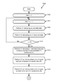
- FIG. 13 a method 1300 for iterative decoding is shown according to one embodiment.
- the method 1300 may be performed in accordance with the present invention in any of the environments depicted in FIGS. 1-12 , among others, in various embodiments.
- more or less operations than those specifically described in FIG. 13 may be included in method 1300 , as would be understood by one of skill in the art upon reading the present descriptions.
- each of the steps of the method 1300 may be performed by any suitable component of the operating environment.
- the method 1300 may be partially or entirely performed by a controller, a processor, a tape drive, or some other device having one or more processors therein.
- the processor e.g., processing circuit(s), chip(s), and/or module(s) implemented in hardware and/or software, and preferably having at least one hardware component, may be utilized in any device to perform one or more steps of the method 1300 .
- Illustrative processors include, but are not limited to, a CPU, an ASIC, a FPGA, etc., combinations thereof, or any other suitable computing device known in the art.
- C1 decoding is performed on the encoded data that includes the product codeword to produce C1-decoded data.
- C2 decoding is performed on the C1-decoded data that includes the product codeword to produce decoded data.
- P may be set to accomplish any desired goal and to provide any number of iterations.
- method 1300 In response to i not equaling P, method 1300 returns to operation 1304 to repeat C1/C2 decoding. In response to i equaling P, method 1300 continues to operation 1312 .
- C1 decoding is performed on the decoded data again to produce final decoded data, and the number of uncorrectable C1 codewords (U) is computed.
- a C2 syndrome check is performed on the final decoded data to compute the number of C2 codewords with nonzero syndrome (W′) in the product codeword.
- a C1 syndrome check is performed on the final decoded data to compute the number of C1 codewords with nonzero syndrome (W) in the product codeword.
- method 1300 relies on obtaining the parameters U, W′, and W in order to determine the error signature. Then, method 1300 continues to A in FIG. 17 to compute the error signature for the decoded product codeword.
- FIG. 17 will be described after the other embodiments for iterative decoding are described in FIGS. 14-16 .
- FIG. 14 a method 1400 for iterative decoding is shown according to one embodiment.
- the method 1400 may be performed in accordance with the present invention in any of the environments depicted in FIGS. 1-12 , among others, in various embodiments.
- more or less operations than those specifically described in FIG. 14 may be included in method 1400 , as would be understood by one of skill in the art upon reading the present descriptions.
- each of the steps of the method 1400 may be performed by any suitable component of the operating environment.
- the method 1400 may be partially or entirely performed by a controller, a processor, a tape drive, or some other device having one or more processors therein.
- the processor e.g., processing circuit(s), chip(s), and/or module(s) implemented in hardware and/or software, and preferably having at least one hardware component, may be utilized in any device to perform one or more steps of the method 1400 .
- Illustrative processors include, but are not limited to, a CPU, an ASIC, a FPGA, etc., combinations thereof, or any other suitable computing device known in the art.
- C1 decoding is performed on the encoded data that includes the product codeword to produce C1-decoded data.
- C2 decoding is performed on the C1-decoded data that includes the product codeword to produce decoded data.
- P may be set to accomplish any desired goal and to provide any number of iterations.
- method 1400 In response to l not equaling P, method 1400 returns to operation 1404 to repeat C1/C2 decoding. In response to i equaling P, method 1400 continues to operation 1412 .
- C1 decoding is performed on the decoded data again to produce C1-post-decoded data.
- C2 decoding is performed on the C1-post-decoded data to produce final decoded data. Furthermore, the number of uncorrectable C2 codewords (U′) is computed.
- a C1 syndrome check is performed on the final decoded data to compute the number of C1 codewords with nonzero syndrome (W) in the product codeword.
- a C2 syndrome check is performed on the final decoded data to compute the number of C2 codewords with nonzero syndrome (W′) in the product codeword.
- method 1400 relies on obtaining the parameters U′, W′, and W in order to determine the error signature. Then, method 1400 continues to B in FIG. 18 to compute the error signature for the decoded product codeword.
- FIG. 18 will be described after the other embodiment for computing an error signature is described in FIG. 17 .
- FIG. 15 a method 1500 for iterative decoding is shown according to one embodiment.
- the method 1500 may be performed in accordance with the present invention in any of the environments depicted in FIGS. 1-12 , among others, in various embodiments.
- more or less operations than those specifically described in FIG. 15 may be included in method 1500 , as would be understood by one of skill in the art upon reading the present descriptions.
- Each of the steps of the method 1500 may be performed by any suitable component of the operating environment.
- the method 1500 may be partially or entirely performed by a controller, a processor, a tape drive, or some other device having one or more processors therein.
- the processor e.g., processing circuit(s), chip(s), and/or module(s) implemented in hardware and/or software, and preferably having at least one hardware component, may be utilized in any device to perform one or more steps of the method 1500 .
- Illustrative processors include, but are not limited to, a CPU, an ASIC, a FPGA, etc., combinations thereof, or any other suitable computing device known in the art.
- C2 decoding is performed on the encoded data that includes the product codeword to produce C2-decoded data.
- C1 decoding is performed on the C2-decoded data that includes the product codeword to produce decoded data.
- P may be set to accomplish any desired goal and to provide any number of iterations, such as 2 full iterations of C2/C1 decoding, 3 full iterations, 4 full iterations, etc.
- method 1500 In response to i not equaling P, method 1500 returns to operation 1504 to repeat C2/C1 decoding. In response to i equaling P, method 1500 continues to operation 1512 .
- C2 decoding is performed on the decoded data again to produce final decoded data and the number of uncorrectable C2 codewords (U′) in the decoded data is computed.
- a C1 syndrome check is performed on the final decoded data to compute the number of C1 codewords with nonzero syndrome (W) in the product codeword.
- a C2 syndrome check is performed on the final decoded data to compute the number of C2 codewords with nonzero syndrome (W′) in the product codeword.
- method 1500 relies on obtaining the parameters U′, W′, and W in order to determine the error signature. Then, method 1500 continues to B in FIG. 18 to compute the error signature for the decoded product codeword.
- FIG. 16 a method 1600 for iterative decoding is shown according to one embodiment.
- the method 1600 may be performed in accordance with the present invention in any of the environments depicted in FIGS. 1-12 , among others, in various embodiments. Of course, more or less operations than those specifically described in FIG. 16 may be included in method 1600 , as would be understood by one of skill in the art upon reading the present descriptions.
- each of the steps of the method 1600 may be performed by any suitable component of the operating environment.
- the method 1600 may be partially or entirely performed by a controller, a processor, a tape drive, or some other device having one or more processors therein.
- the processor e.g., processing circuit(s), chip(s), and/or module(s) implemented in hardware and/or software, and preferably having at least one hardware component, may be utilized in any device to perform one or more steps of the method 1600 .
- Illustrative processors include, but are not limited to, a CPU, an ASIC, a FPGA, etc., combinations thereof, or any other suitable computing device known in the art.
- C2 decoding is performed on the encoded data that includes the product codeword to produce C2-decoded data.
- C1 decoding is performed on the C2-decoded data that includes the product codeword to produce decoded data.
- P may be set to accomplish any desired goal and to provide any number of iterations.
- method 1600 In response to i not equaling P, method 1600 returns to operation 1604 to repeat C2/C1 decoding. In response to i equaling P, method 1600 continues to operation 1612 .
- C2 decoding is performed on the decoded data to produce C2-post-decoded data.
- C1 decoding is performed on the C2-post-decoded data to produce final decoded data. Also, the number of uncorrectable C1 codewords (U) in the final decoded data is computed.
- a C2 syndrome check is performed on the final decoded data to compute the number of C2 codewords with nonzero syndrome (W′) in the product codeword.
- a C1 syndrome check is performed on the final decoded data to compute the number of C1 codewords with nonzero syndrome (W) in the product codeword.
- method 1600 relies on obtaining the parameters U, W′, and W in order to determine the error signature. Then, method 1600 continues to A in FIG. 17 to compute the error signature for the decoded product codeword.
- a method 1700 is shown, according to one embodiment, which may be performed after either of the methods depicted in FIGS. 13 and 16 .
- the method 1700 may be performed in accordance with the present invention in any of the environments depicted in FIGS. 1-12 , among others, in various embodiments.
- more or less operations than those specifically described in FIG. 17 may be included in method 1700 , as would be understood by one of skill in the art upon reading the present descriptions.
- Each of the steps of the method 1700 may be performed by any suitable component of the operating environment.
- the method 1700 may be partially or entirely performed by a controller, a processor, a tape drive, or some other device having one or more processors therein.
- the processor e.g., processing circuit(s), chip(s), and/or module(s) implemented in hardware and/or software, and preferably having at least one hardware component, may be utilized in any device to perform one or more steps of the method 1700 .
- Illustrative processors include, but are not limited to, a CPU, an ASIC, a FPGA, etc., combinations thereof, or any other suitable computing device known in the art.
- U uncorrectable C1 codewords
- operation 1706 it is determined whether the number of C2 codewords with nonzero syndrome in the product codeword (illegal C2 codewords) that are detected after checking C2 syndrome is less than the minimum Hamming distance (d1) for the C1 code (e.g., W′ ⁇ d1). In response to W′ being less than d1, method 1700 continues to operation 1708 ; otherwise, method 1700 moves to operation 1716 .
- d1 the minimum Hamming distance
- a channel error is detected in response to U 0 , and method 1700 continues to operation 1718 .
- operation 1714 it is determined that decoding has been successful, and method 1700 continues to operation 1726 .
- a C1 decoder error is detected in response to W′ ⁇ d1, and method 1700 continues to operation 1728 .
- W nonzero syndrome
- W nonzero syndrome
- one or more actions may be performed to rectify the particular type of error that is identified by the error signature prior to re-reading the encoded data from the medium, and/or attempting iterative decoding again.
- These actions may include adjustment of the medium's physical position laterally relative to the read sensor(s), movement of the medium forward or backward in respect to the read sensor(s), usage of more or less intensive decoding algorithm(s) to decode the encoded data, use of one or more different decoding algorithm(s) to decode the encoded data, increase or decrease in number of iterations in the decoding scheme, increase or decrease in speed of movement of the medium during re-reading, etc.
- a method 1800 is shown, according to one embodiment, which may be performed after either of the methods depicted in FIGS. 14 and 15 .
- the method 1800 may be performed in accordance with the present invention in any of the environments depicted in FIGS. 1-12 , among others, in various embodiments.
- more or less operations than those specifically described in FIG. 18 may be included in method 1800 , as would be understood by one of skill in the art upon reading the present descriptions.
- Each of the steps of the method 1800 may be performed by any suitable component of the operating environment.
- the method 1800 may be partially or entirely performed by a controller, a processor, a tape drive, or some other device having one or more processors therein.
- the processor e.g., processing circuit(s), chip(s), and/or module(s) implemented in hardware and/or software, and preferably having at least one hardware component, may be utilized in any device to perform one or more steps of the method 1800 .
- Illustrative processors include, but are not limited to, a CPU, an ASIC, a FPGA, etc., combinations thereof, or any other suitable computing device known in the art.
- U′ the number of uncorrectable C2 codewords
- operation 1806 it is determined whether the number of C1 codewords with nonzero syndrome in the product codeword (illegal C1 codewords) that are detected after checking C1 syndrome is less than the minimum Hamming distance (d2) for the C2 code (e.g., W ⁇ d2). In response to W being less than d2, method 1800 continues to operation 1808 ; otherwise, method 1800 moves to operation 1816 .
- d2 the minimum Hamming distance
- a channel error is detected in response to U′ ⁇ 0, and method 1800 continues to operation 1818 .
- operation 1814 it is determined that decoding has been successful, and method 1800 continues to operation 1826 .
- a C2 decoder error is detected in response to W ⁇ d2, and method 1800 continues to operation 1828 .
- W′ C2 codewords with nonzero syndrome
- U′ uncorrectable C2 codewords
- W′ nonzero syndrome
- one or more actions may be performed to rectify the particular type of error that is identified by the error signature prior to re-reading the encoded data from the medium, and/or attempting iterative decoding again.
- These actions may include adjustment of the medium's physical position laterally relative to the read sensor(s), movement of the medium forward or backward in respect to the read sensor(s), usage of more or less intensive decoding algorithm(s) to decode the encoded data, use of one or more different decoding algorithm(s) to decode the encoded data, increase or decrease in number of iterations in the decoding scheme, increase or decrease in speed of movement of the medium during re-reading, etc.
- FIG. 19 a method 1900 for iterative decoding is shown according to one embodiment.
- the method 1900 may be performed in accordance with the present invention in any of the environments depicted in FIGS. 1-12 , among others, in various embodiments.
- more or less operations than those specifically described in FIG. 19 may be included in method 1900 , as would be understood by one of skill in the art upon reading the present descriptions.
- Each of the steps of the method 1900 may be performed by any suitable component of the operating environment.
- the method 1900 may be partially or entirely performed by a controller, a processor, a tape drive, or some other device having one or more processors therein.
- the processor e.g., processing circuit(s), chip(s), and/or module(s) implemented in hardware and/or software, and preferably having at least one hardware component, may be utilized in any device to perform one or more steps of the method 1900 .
- Illustrative processors include, but are not limited to, a CPU, an ASIC, a FPGA, etc., combinations thereof, or any other suitable computing device known in the art.
- C1 decoding is performed on the encoded data that includes the product codeword to produce C1-decoded data.
- C2 decoding is performed on the C1-decoded data that includes the product codeword to produce decoded data.
- P may be set to accomplish any desired goal and to provide any number of iterations.
- method 1900 In response to i not equaling P, method 1900 returns to operation 1904 to repeat C1/C2 decoding. In response to i equaling P, method 1900 continues to operation 1912 .
- C1 decoding is performed on the decoded data again to produce final decoded data, and the number of uncorrectable C1 codewords (U) in the product codeword is computed.
- method 1900 continues to C in FIG. 20 to compute the error signature for the decoded product codeword.
- a method 2000 is shown according to one embodiment.
- the method 2000 may be performed in accordance with the present invention in any of the environments depicted in FIGS. 1-12 , among others, in various embodiments.
- more or less operations than those specifically described in FIG. 20 may be included in method 2000 , as would be understood by one of skill in the art upon reading the present descriptions.
- each of the steps of the method 2000 may be performed by any suitable component of the operating environment.
- the method 2000 may be partially or entirely performed by a controller, a processor, a tape drive, or some other device having one or more processors therein.
- the processor e.g., processing circuit(s), chip(s), and/or module(s) implemented in hardware and/or software, and preferably having at least one hardware component, may be utilized in any device to perform one or more steps of the method 2000 .
- Illustrative processors include, but are not limited to, a CPU, an ASIC, a FPGA, etc., combinations thereof, or any other suitable computing device known in the art.
- method 2000 may start with operation 2002 , where a C2 syndrome check is performed on the final decoded data, to compute a number of nonzero C2 syndromes (illegal C2 codewords), referred to as W′.
- C2 error locations are computed based on the illegal C2 codewords and other information obtained during decoding.
- C2 error locations are converted to C1 error locations. Because C1 and C2 codewords are orthogonal in the product codeword, the location of an error in a C2 codeword may be converted to a location of an error in a C1 codeword, and vice versa.
- a number of C1 codewords that have at least d1 symbol errors (D), other than uncorrectable C1 codewords (U), is computed.
- a number of C1 codewords that have less than d1 symbol errors (M), other than uncorrectable C1 codewords (U) is computed. Both of these values, D and M, are computed after C2 error locations are determined.
- one or more actions may be performed to rectify the particular type of error that is identified by the error signature prior to re-reading the encoded data from the medium, and/or attempting iterative decoding again.
- These actions may include adjustment of the medium's physical position laterally relative to the read sensor(s), movement of the medium forward or backward in respect to the read sensor(s), usage of more or less intensive decoding algorithm(s) to decode the encoded data, use of one or more different decoding algorithm(s) to decode the encoded data, increase or decrease in number of iterations in the decoding scheme, increase or decrease in speed of movement of the medium during re-reading, etc.
- Method 2000 is an error signature calculation which relies on the determination of U, and the computation of D and M, after C1/C2 iterative decoding that ends with C1 decoding as a last decoding operation, such as the method 1900 shown in FIG. 19 as an example.
- a method 2100 is shown according to one embodiment.
- the method 2100 may be performed in accordance with the present invention in any of the environments depicted in FIGS. 1-12 , among others, in various embodiments.
- more or less operations than those specifically described in FIG. 21 may be included in method 2100 , as would be understood by one of skill in the art upon reading the present descriptions.
- each of the steps of the method 2100 may be performed by any suitable component of the operating environment.
- the method 2100 may be partially or entirely performed by a controller, a processor, a tape drive, or some other device having one or more processors therein.
- the processor e.g., processing circuit(s), chip(s), and/or module(s) implemented in hardware and/or software, and preferably having at least one hardware component, may be utilized in any device to perform one or more steps of the method 2100 .
- Illustrative processors include, but are not limited to, a CPU, an ASIC, a FPGA, etc., combinations thereof, or any other suitable computing device known in the art.
- C2 decoding is performed on the encoded data that includes the product codeword to produce C2-decoded data.
- C1 decoding is performed on the C2-decoded data that includes the product codeword to produce decoded data.
- P may be set to accomplish any desired goal and to provide any number of iterations.
- method 2100 In response to i not equaling P, method 2100 returns to operation 2104 to repeat C2/C1 decoding. In response to i equaling P, method 2100 continues to operation 2112 .
- C2 decoding is performed on the decoded data again to produce final decoded data. Then, method 2100 continues to D in FIG. 22 to compute the error signature for the decoded product codeword.
- a method 2200 is shown according to one embodiment.
- the method 2200 may be performed in accordance with the present invention in any of the environments depicted in FIGS. 1-12 , among others, in various embodiments.
- more or less operations than those specifically described in FIG. 22 may be included in method 2200 , as would be understood by one of skill in the art upon reading the present descriptions.
- each of the steps of the method 2200 may be performed by any suitable component of the operating environment.
- the method 2200 may be partially or entirely performed by a controller, a processor, a tape drive, or some other device having one or more processors therein.
- the processor e.g., processing circuit(s), chip(s), and/or module(s) implemented in hardware and/or software, and preferably having at least one hardware component, may be utilized in any device to perform one or more steps of the method 2200 .
- Illustrative processors include, but are not limited to, a CPU, an ASIC, a FPGA, etc., combinations thereof, or any other suitable computing device known in the art.
- method 2200 may start with operation 2202 , where a C1 syndrome check is performed on the final decoded data, to compute a number of nonzero C1 syndromes (illegal C1 codewords), referred to as W.
- a C1 syndrome check is performed on the final decoded data, to compute a number of nonzero C1 syndromes (illegal C1 codewords), referred to as W.
- C1 error locations are computed based on the illegal C1 codewords and other information obtained during decoding.
- C1 error locations are converted to C2 error locations. Because C1 and C2 codewords are orthogonal in the product codeword, the location of an error in a C1 codeword may be converted to a location of an error in a C2 codeword, and vice versa.
- a number of C2 codewords that have at least d2 symbol errors (D′), other than uncorrectable C2 codewords (U′), is computed.
- a number of C2 codewords that have less than d2 symbol errors (M′), other than uncorrectable C2 codewords (U′) is computed. Both of these values, D′ and M′, are computed after C1 error locations are determined.
- one or more actions may be performed to rectify the particular type of error that is identified by the error signature prior to re-reading the encoded data from the medium, and/or attempting iterative decoding again.
- These actions may include adjustment of the medium's physical position laterally relative to the read sensor(s), movement of the medium forward or backward in respect to the read sensor(s), usage of more or less intensive decoding algorithm(s) to decode the encoded data, use of one or more different decoding algorithm(s) to decode the encoded data, increase or decrease in number of iterations in the decoding scheme, increase or decrease in speed of movement of the medium during re-reading, etc.
- Method 2200 is an error signature calculation which relies on the determination of U′, and the computation of D′ and M′, after C2/C1 iterative decoding that ends with a C2 decoding operation as a last decoding operation.
- the error correction status for the C1 and C2 decoders and the C1 and C2 syndrome checkers may be used to identify whether an error is due to a soft failure in memory, is a mis-correction by either the C1 decoder or the C2 decoder, or is an uncorrectable error.
- Table 3 shows the relationships between the decoder status, syndrome checker status, and what type of error is present, according to one embodiment.
- the present invention may be a system, a method, and/or a computer program product.
- the computer program product may include a computer readable storage medium (or media) having computer readable program instructions thereon for causing a processor to carry out aspects of the present invention.
- the computer readable storage medium can be a tangible device that can retain and store instructions for use by an instruction execution device.
- the computer readable storage medium may be, for example, but is not limited to, an electronic storage device, a magnetic storage device, an optical storage device, an electromagnetic storage device, a semiconductor storage device, or any suitable combination of the foregoing.
- a non-exhaustive list of more specific examples of the computer readable storage medium includes the following: a portable computer diskette, a hard disk, a random access memory (RAM), a read-only memory (ROM), an erasable programmable read-only memory (EPROM or Flash memory), a static random access memory (SRAM), a portable compact disc read-only memory (CD-ROM), a digital versatile disk (DVD), a memory stick, a floppy disk, a mechanically encoded device such as punch-cards or raised structures in a groove having instructions recorded thereon, and any suitable combination of the foregoing.
- RAM random access memory
- ROM read-only memory
- EPROM or Flash memory erasable programmable read-only memory
- SRAM static random access memory
- CD-ROM compact disc read-only memory
- DVD digital versatile disk
- memory stick a floppy disk
- a mechanically encoded device such as punch-cards or raised structures in a groove having instructions recorded thereon
- a computer readable storage medium is not to be construed as being transitory signals per se, such as radio waves or other freely propagating electromagnetic waves, electromagnetic waves propagating through a waveguide or other transmission media (e.g., light pulses passing through a fiber-optic cable), or electrical signals transmitted through a wire.
- Computer readable program instructions described herein can be downloaded to respective computing/processing devices from a computer readable storage medium or to an external computer or external storage device via a network, for example, the Internet, a local area network, a wide area network and/or a wireless network.
- the network may comprise copper transmission cables, optical transmission fibers, wireless transmission, routers, firewalls, switches, gateway computers and/or edge servers.
- a network adapter card or network interface in each computing/processing device receives computer readable program instructions from the network and forwards the computer readable program instructions for storage in a computer readable storage medium within the respective computing/processing device.
- Computer readable program instructions for carrying out operations of the present invention may be assembler instructions, instruction-set-architecture (ISA) instructions, machine instructions, machine dependent instructions, microcode, firmware instructions, state-setting data, or either source code or object code written in any combination of one or more programming languages, including an object oriented programming language such as Smalltalk, C++ or the like, and conventional procedural programming languages, such as the “C” programming language or similar programming languages.
- the computer readable program instructions may execute entirely on the user's computer, partly on the user's computer, as a stand-alone software package, partly on the user's computer and partly on a remote computer or entirely on the remote computer or server.
- the remote computer may be connected to the user's computer through any type of network, including a local area network (LAN) or a wide area network (WAN), or the connection may be made to an external computer (for example, through the Internet using an Internet Service Provider).
- electronic circuitry including, for example, programmable logic circuitry, field-programmable gate arrays (FPGA), or programmable logic arrays (PLA) may execute the computer readable program instructions by utilizing state information of the computer readable program instructions to personalize the electronic circuitry, in order to perform aspects of the present invention.
- These computer readable program instructions may be provided to a processor of a general purpose computer, special purpose computer, or other programmable data processing apparatus to produce a machine, such that the instructions, which execute via the processor of the computer or other programmable data processing apparatus, create means for implementing the functions/acts specified in the flowchart and/or block diagram block or blocks.
- These computer readable program instructions may also be stored in a computer readable storage medium that can direct a computer, a programmable data processing apparatus, and/or other devices to function in a particular manner, such that the computer readable storage medium having instructions stored therein comprises an article of manufacture including instructions which implement aspects of the function/act specified in the flowchart and/or block diagram block or blocks.
- the computer readable program instructions may also be loaded onto a computer, other programmable data processing apparatus, or other device to cause a series of operational steps to be performed on the computer, other programmable apparatus or other device to produce a computer implemented process, such that the instructions which execute on the computer, other programmable apparatus, or other device implement the functions/acts specified in the flowchart and/or block diagram block or blocks.
- each block in the flowchart or block diagrams may represent a module, segment, or portion of instructions, which comprises one or more executable instructions for implementing the specified logical function(s).
- the functions noted in the block may occur out of the order noted in the figures.
- two blocks shown in succession may, in fact, be executed substantially concurrently, or the blocks may sometimes be executed in the reverse order, depending upon the functionality involved.
- a system may include a processor and logic integrated with and/or executable by the processor, the logic being configured to perform one or more of the process steps recited herein.
- the processor has logic embedded therewith as hardware logic, such as an ASIC, a FPGA, etc.
- the logic is hardware logic, software logic such as firmware, part of an operating system, part of an application program, etc., or some combination of hardware and software logic that is accessible by the processor and configured to cause the processor to perform some functionality upon execution by the processor.
- Software logic may be stored on local and/or remote memory of any memory type, as known in the art. Any processor known in the art may be used, such as a software processor module and/or a hardware processor such as an ASIC, a FPGA, a CPU, an integrated circuit (IC), a graphics processing unit (GPU), etc.
- embodiments of the present invention may be provided in the form of a service deployed on behalf of a customer to offer service on demand.
Landscapes
- Engineering & Computer Science (AREA)
- Physics & Mathematics (AREA)
- Probability & Statistics with Applications (AREA)
- Theoretical Computer Science (AREA)
- Signal Processing (AREA)
- Error Detection And Correction (AREA)
- Detection And Correction Of Errors (AREA)
Priority Applications (7)
| Application Number | Priority Date | Filing Date | Title |
|---|---|---|---|
| US14/968,726 US9413392B1 (en) | 2015-12-14 | 2015-12-14 | Post-decoding error check with diagnostics for product codes |
| US15/181,200 US10298272B2 (en) | 2015-12-14 | 2016-06-13 | Post-decoding error check with diagnostics for product codes |
| JP2018522922A JP6817301B2 (ja) | 2015-12-14 | 2016-11-29 | 積符号のためのダイアグノスティクスを伴う復号後エラー・チェック |
| CN201680073311.8A CN108370252B (zh) | 2015-12-14 | 2016-11-29 | 对乘积码诊断的后解码错误检查 |
| PCT/IB2016/057180 WO2017103716A1 (en) | 2015-12-14 | 2016-11-29 | Post-decoding error check with diagnostics for product codes |
| DE112016003638.8T DE112016003638B4 (de) | 2015-12-14 | 2016-11-29 | Auf eine Decodierung folgende Fehlerprüfung mit Diagnose für Produktcodes |
| GB1803554.3A GB2562352B (en) | 2015-12-14 | 2016-11-29 | Post-decoding error check with diagnostics for product codes |
Applications Claiming Priority (1)
| Application Number | Priority Date | Filing Date | Title |
|---|---|---|---|
| US14/968,726 US9413392B1 (en) | 2015-12-14 | 2015-12-14 | Post-decoding error check with diagnostics for product codes |
Related Child Applications (1)
| Application Number | Title | Priority Date | Filing Date |
|---|---|---|---|
| US15/181,200 Continuation US10298272B2 (en) | 2015-12-14 | 2016-06-13 | Post-decoding error check with diagnostics for product codes |
Publications (1)
| Publication Number | Publication Date |
|---|---|
| US9413392B1 true US9413392B1 (en) | 2016-08-09 |
Family
ID=56556546
Family Applications (2)
| Application Number | Title | Priority Date | Filing Date |
|---|---|---|---|
| US14/968,726 Active US9413392B1 (en) | 2015-12-14 | 2015-12-14 | Post-decoding error check with diagnostics for product codes |
| US15/181,200 Active 2036-06-25 US10298272B2 (en) | 2015-12-14 | 2016-06-13 | Post-decoding error check with diagnostics for product codes |
Family Applications After (1)
| Application Number | Title | Priority Date | Filing Date |
|---|---|---|---|
| US15/181,200 Active 2036-06-25 US10298272B2 (en) | 2015-12-14 | 2016-06-13 | Post-decoding error check with diagnostics for product codes |
Country Status (6)
| Country | Link |
|---|---|
| US (2) | US9413392B1 (de) |
| JP (1) | JP6817301B2 (de) |
| CN (1) | CN108370252B (de) |
| DE (1) | DE112016003638B4 (de) |
| GB (1) | GB2562352B (de) |
| WO (1) | WO2017103716A1 (de) |
Cited By (3)
| Publication number | Priority date | Publication date | Assignee | Title |
|---|---|---|---|---|
| WO2017103716A1 (en) * | 2015-12-14 | 2017-06-22 | International Business Machines Corporation | Post-decoding error check with diagnostics for product codes |
| US11101823B2 (en) * | 2019-05-24 | 2021-08-24 | Kioxia Corporation | Memory system |
| US20220229725A1 (en) * | 2021-01-21 | 2022-07-21 | Kioxia Corporation | Soft error detection and correction for data storage devices |
Families Citing this family (4)
| Publication number | Priority date | Publication date | Assignee | Title |
|---|---|---|---|---|
| RU2693190C1 (ru) * | 2018-07-02 | 2019-07-01 | Федеральное государственное бюджетное образовательное учреждение высшего образования "Владимирский Государственный Университет имени Александра Григорьевича и Николая Григорьевича Столетовых" (ВлГУ) | Способ диагностики недвоичных блоковых кодов |
| GB2579590B (en) * | 2018-12-04 | 2021-10-13 | Imagination Tech Ltd | Workload repetition redundancy |
| GB2579591B (en) | 2018-12-04 | 2022-10-26 | Imagination Tech Ltd | Buffer checker |
| US11750221B1 (en) | 2022-03-28 | 2023-09-05 | Samsung Electronics Co., Ltd. | Encoding and decoding of data using generalized LDPC codes |
Citations (6)
| Publication number | Priority date | Publication date | Assignee | Title |
|---|---|---|---|---|
| US5684810A (en) * | 1993-12-28 | 1997-11-04 | Mitsubishi Denki Kabushiki Kaisha | Error correcting decoder and error correction decoding method |
| US20030126546A1 (en) * | 2002-01-31 | 2003-07-03 | Hachiro Fujita | Decoding method, decoding apparatus and digital transmission system of product code |
| US20100293432A1 (en) * | 2009-05-13 | 2010-11-18 | Yoshikuni Miyata | Error-correction coding method, error-correction decoding method, error-correction coding apparatus, and error-correction decoding apparatus |
| US8467249B2 (en) | 2010-07-06 | 2013-06-18 | Densbits Technologies Ltd. | Systems and methods for storing, retrieving, and adjusting read thresholds in flash memory storage system |
| US8566672B2 (en) | 2011-03-22 | 2013-10-22 | Freescale Semiconductor, Inc. | Selective checkbit modification for error correction |
| US8806295B2 (en) | 2012-05-24 | 2014-08-12 | International Business Machines Corporation | Mis-correction and no-correction rates for error control |
Family Cites Families (14)
| Publication number | Priority date | Publication date | Assignee | Title |
|---|---|---|---|---|
| US4104735A (en) | 1976-09-15 | 1978-08-01 | Siemens Aktiengesellschaft | Arrangement for addressing a MOS store |
| US5974580A (en) | 1997-07-23 | 1999-10-26 | Cirrus Logic, Inc. | Concurrent row/column syndrome generator for a product code |
| JP3880144B2 (ja) | 1997-08-21 | 2007-02-14 | キヤノン株式会社 | 誤り訂正方法 |
| EP1146650A1 (de) * | 2000-04-10 | 2001-10-17 | Hewlett-Packard Company, A Delaware Corporation | Fehlerkorrektur für Datenauzeichnung und Übertragung |
| CN1471763A (zh) * | 2001-08-28 | 2004-01-28 | 连宇通信有限公司 | 对源数据元素进行纠错编码的方法及相应的迭代译码器 |
| TWI241073B (en) * | 2005-01-03 | 2005-10-01 | Sunplus Technology Co Ltd | Decoding device for product code decoding and method thereof |
| JP2008016151A (ja) * | 2006-07-07 | 2008-01-24 | Canon Inc | データ処理方法及び再生装置 |
| US8046660B2 (en) * | 2006-08-07 | 2011-10-25 | Marvell World Trade Ltd. | System and method for correcting errors in non-volatile memory using product codes |
| US7912028B2 (en) * | 2007-05-31 | 2011-03-22 | Agere Systems Inc. | Reducing false detection in an HSDPA 3G terminal |
| WO2009122307A2 (en) * | 2008-03-31 | 2009-10-08 | Marvell Israel ( Misl) Ltd. | Method and apparatus for decoding |
| JPWO2010029771A1 (ja) * | 2008-09-12 | 2012-02-02 | シャープ株式会社 | 無線通信システム、無線通信方法及び通信装置 |
| CN101483443B (zh) * | 2008-12-26 | 2012-07-25 | 中国航空无线电电子研究所 | Turbo乘积码优化编译码算法的FPGA实现方法 |
| US9214964B1 (en) | 2012-09-24 | 2015-12-15 | Marvell International Ltd. | Systems and methods for configuring product codes for error correction in a hard disk drive |
| US9413392B1 (en) | 2015-12-14 | 2016-08-09 | International Business Machines Corporation | Post-decoding error check with diagnostics for product codes |
-
2015
- 2015-12-14 US US14/968,726 patent/US9413392B1/en active Active
-
2016
- 2016-06-13 US US15/181,200 patent/US10298272B2/en active Active
- 2016-11-29 WO PCT/IB2016/057180 patent/WO2017103716A1/en active Application Filing
- 2016-11-29 JP JP2018522922A patent/JP6817301B2/ja active Active
- 2016-11-29 CN CN201680073311.8A patent/CN108370252B/zh active Active
- 2016-11-29 DE DE112016003638.8T patent/DE112016003638B4/de active Active
- 2016-11-29 GB GB1803554.3A patent/GB2562352B/en active Active
Patent Citations (6)
| Publication number | Priority date | Publication date | Assignee | Title |
|---|---|---|---|---|
| US5684810A (en) * | 1993-12-28 | 1997-11-04 | Mitsubishi Denki Kabushiki Kaisha | Error correcting decoder and error correction decoding method |
| US20030126546A1 (en) * | 2002-01-31 | 2003-07-03 | Hachiro Fujita | Decoding method, decoding apparatus and digital transmission system of product code |
| US20100293432A1 (en) * | 2009-05-13 | 2010-11-18 | Yoshikuni Miyata | Error-correction coding method, error-correction decoding method, error-correction coding apparatus, and error-correction decoding apparatus |
| US8467249B2 (en) | 2010-07-06 | 2013-06-18 | Densbits Technologies Ltd. | Systems and methods for storing, retrieving, and adjusting read thresholds in flash memory storage system |
| US8566672B2 (en) | 2011-03-22 | 2013-10-22 | Freescale Semiconductor, Inc. | Selective checkbit modification for error correction |
| US8806295B2 (en) | 2012-05-24 | 2014-08-12 | International Business Machines Corporation | Mis-correction and no-correction rates for error control |
Non-Patent Citations (4)
| Title |
|---|
| Al-Shaikhi et al., Modified algorithm for hard decision decoding of product codes, 2004, IEEE, Communications Society, pp. 1760 to 1763. * |
| Bentley, S. R. et al., U.S. Appl. No. 15/013,821, dated Feb. 2, 2016. |
| Cideciyan et al., U.S. Appl. No. 14/328,510, filed Jul. 10, 2014. |
| Zhi et al., FPGA implementation of a modified hard decision decoding for 2-D TPC, 2009, IEEE, pp. 225-228. * |
Cited By (10)
| Publication number | Priority date | Publication date | Assignee | Title |
|---|---|---|---|---|
| WO2017103716A1 (en) * | 2015-12-14 | 2017-06-22 | International Business Machines Corporation | Post-decoding error check with diagnostics for product codes |
| GB2562352A (en) * | 2015-12-14 | 2018-11-14 | Ibm | Post-decoding error check with diagnostics for product codes |
| GB2562352B (en) * | 2015-12-14 | 2019-03-06 | Ibm | Post-decoding error check with diagnostics for product codes |
| US10298272B2 (en) | 2015-12-14 | 2019-05-21 | International Business Machines Corporation | Post-decoding error check with diagnostics for product codes |
| US11101823B2 (en) * | 2019-05-24 | 2021-08-24 | Kioxia Corporation | Memory system |
| US11515896B2 (en) * | 2019-05-24 | 2022-11-29 | Kioxia Corporation | Memory system |
| US20230054732A1 (en) * | 2019-05-24 | 2023-02-23 | Kioxia Corporation | Memory system |
| US11784665B2 (en) * | 2019-05-24 | 2023-10-10 | Kioxia Corporation | Memory system |
| US20220229725A1 (en) * | 2021-01-21 | 2022-07-21 | Kioxia Corporation | Soft error detection and correction for data storage devices |
| US11693733B2 (en) * | 2021-01-21 | 2023-07-04 | Kioxia Corporation | Soft error detection and correction for data storage devices |
Also Published As
| Publication number | Publication date |
|---|---|
| GB2562352A (en) | 2018-11-14 |
| DE112016003638T5 (de) | 2018-05-03 |
| CN108370252B (zh) | 2021-06-15 |
| CN108370252A (zh) | 2018-08-03 |
| US20170170849A1 (en) | 2017-06-15 |
| JP2019503603A (ja) | 2019-02-07 |
| JP6817301B2 (ja) | 2021-01-20 |
| WO2017103716A1 (en) | 2017-06-22 |
| DE112016003638B4 (de) | 2023-09-21 |
| GB2562352B (en) | 2019-03-06 |
| GB201803554D0 (en) | 2018-04-18 |
| US10298272B2 (en) | 2019-05-21 |
Similar Documents
| Publication | Publication Date | Title |
|---|---|---|
| US10298272B2 (en) | Post-decoding error check with diagnostics for product codes | |
| JP4833173B2 (ja) | 復号化器、符号化・復号化装置及び記録再生装置 | |
| US9455749B2 (en) | Combination error and erasure decoding for product codes | |
| US9985658B2 (en) | Decoding of product codes | |
| US9542265B2 (en) | Unequal error protection scheme for headerized sub data sets | |
| US8910012B2 (en) | Block-interleaved and error correction code (ECC)-encoded sub data set (SDS) format | |
| US11031042B2 (en) | Efficient rewrite using larger codeword sizes | |
| US9564171B2 (en) | Reconstructive error recovery procedure (ERP) using reserved buffer | |
| US10824346B2 (en) | Logical format utilizing lateral encoding of data for storage on magnetic tape | |
| US20170315862A1 (en) | Detection of multiple bit errors in random access memories | |
| US9564925B1 (en) | Pipelined architecture for iterative decoding of product codes | |
| US9712188B2 (en) | Decoding data stored with three orthogonal codewords | |
| US9477552B1 (en) | Priority-based decoding |
Legal Events
| Date | Code | Title | Description |
|---|---|---|---|
| AS | Assignment |
Owner name: INTERNATIONAL BUSINESS MACHINES CORPORATION, NEW Y Free format text: ASSIGNMENT OF ASSIGNORS INTEREST;ASSIGNORS:BENTLEY, STEVEN R.;CIDECIYAN, ROY D.;HUTCHINS, ROBERT A.;AND OTHERS;SIGNING DATES FROM 20151211 TO 20151214;REEL/FRAME:037287/0767 |
|
| STCF | Information on status: patent grant |
Free format text: PATENTED CASE |
|
| MAFP | Maintenance fee payment |
Free format text: PAYMENT OF MAINTENANCE FEE, 4TH YEAR, LARGE ENTITY (ORIGINAL EVENT CODE: M1551); ENTITY STATUS OF PATENT OWNER: LARGE ENTITY Year of fee payment: 4 |
|
| FEPP | Fee payment procedure |
Free format text: MAINTENANCE FEE REMINDER MAILED (ORIGINAL EVENT CODE: REM.); ENTITY STATUS OF PATENT OWNER: LARGE ENTITY |