US941336A - Telephone-cabinet. - Google Patents
Telephone-cabinet. Download PDFInfo
- Publication number
- US941336A US941336A US47494209A US1909474942A US941336A US 941336 A US941336 A US 941336A US 47494209 A US47494209 A US 47494209A US 1909474942 A US1909474942 A US 1909474942A US 941336 A US941336 A US 941336A
- Authority
- US
- United States
- Prior art keywords
- cabinet
- backboard
- telephone
- hangers
- clips
- Prior art date
- Legal status (The legal status is an assumption and is not a legal conclusion. Google has not performed a legal analysis and makes no representation as to the accuracy of the status listed.)
- Expired - Lifetime
Links
- 238000010276 construction Methods 0.000 description 3
- 239000002184 metal Substances 0.000 description 2
- 238000005192 partition Methods 0.000 description 1
- 229920000136 polysorbate Polymers 0.000 description 1
Images
Classifications
-
- H—ELECTRICITY
- H04—ELECTRIC COMMUNICATION TECHNIQUE
- H04M—TELEPHONIC COMMUNICATION
- H04M1/00—Substation equipment, e.g. for use by subscribers
- H04M1/02—Constructional features of telephone sets
- H04M1/0297—Telephone sets adapted to be mounted on a desk or on a wall
Definitions
- This invention relates to telephone cabinets.
- leretofore telephone cabinets have been constructed principally from a backboard having permanently connected therewith side, top and bottom walls which are generally connected by partitions or the like for supporting batteries or instruments forming a part of the telephone.
- the cabinet heretofore is generally provided with a hinged door in order that access can be gained to the interior should it be desired to inspect or repair the instrument or any parts thereof. it is often necessary in telephones to separate the backboard from the remaining structure forming the cabinet in order that access can be gained to the cabinet from the rear thereof.
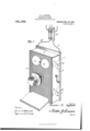
- F igure 1 is a perspective view of the telephone cabinet.
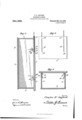
- Fig. 2 is a vertical section taken through the cabinet.
- Fig. 3 is a rear view of a portion of the cabinet.
- Fig. t is a horizontal section through the cabinet taken on the line of the contact pieces.
- a telephone cabinet embodying a backboard or support 1 and a body portion or housing 2 comprising spaced side walls 3 and connecting bottom and top walls a.
- One of the side walls has hingedly connected thereto a door or front member 5.
- Adjacentto the lower end of the backboard is shown horizontally disposed spaced clips, hangers or similar elements 7 each comprising a single length of metal having a shank portion 8 anchored to thebackboard preferably by passing the shank therethrough and by heading their outer extremities.
- the metal forming the clips, hangers or the like is bent upwardly as indicated at 9 and outwardly at 10 and then upwardly in arcuate form to provide a finger 11 spaced from the backboard as will be clearly appreciated upon reference to Fig. 2 of the drawings.
- the outwardly directed portions 10 of the clips, hangers or the like provide shoulders for a purpose to be hereinafter more fully described.
- Similar clips, hangers or the like are carried by the backboard adjacent to the upper end thereof and as shown, these clips are provided with shanks 12 which have headed portions 13 disposed at the lower ends of spaced vertical grooves 1d and 15 formed in the backboard upon the rear side thereof.
- the backboard is also provided with vertically disposed passages 16 and 17 which open at their upper ends onto the upper edge of the backboard and which have their lower ends communicating with the grooves. 14 and 15.
- switch is indicated at A in Fig. 1 of the drawings and the branch wires B and C of the switch are extended downwardly through the passages 16 and 17 and into the grooves 14 and 15, and as shown the terminal ends of the wires are connected to the shanks 12 of the clips, adjacent to the upper end of the backboard.
- the switch A described by me is of course unnecessary but is used for the purpose of convenience. It will of course be understood that the wires B and G are connected with the central station of the telephone instrument.
- Contact members 18 are secured to the side walls 3 of the body portion 2 of the cabinet and are provided with inwardly directed pi'ns19- adapted to rest upon the shoulders 20 of the clips adjacent to the upper end of the backboard.
- the contact pieces 18 are connected with wires 21 to be attached to the telephone instrument.
- the side walls 3 carry at their lower' ends inwardly directed pins 22 adapted to rest upon the shoulders 10 of the clips, hangers or the like 7.
- a cabinet of the class described comprising a housing having a hinged closure at the front, said housing having an open back portion, hangers extending into the housing from said open back portion and located adjacent to the sides of the said housing, electrical connect-ions for said hangers, and electrically connected contact pieces carried by the housing at the side thereof adapted to frictionally engage portions of the said hangers and provided with lateral pins adapted for locking engagement with said hangers.
- a cabinet comprising a housing having a hinged closure at the front thereof, said housing having an open back portion, a backboard for closing the open back port-ion of the housing, electrically connected hangers extending from the backboard, said hangers each having a shank portion engaged with the backboard and provided with a horizontally disposed shoulder and an upwardly extending finger disposed in spaced relation to the backboard, and con tact members secured to the sides of the said housing adapted to frictionally engage the said hangers and provided with horizontally disposed pins adapted to rest upon the shoulders of said hangers.
Landscapes
- Engineering & Computer Science (AREA)
- Signal Processing (AREA)
- Structure Of Telephone Exchanges (AREA)
Description
0. E. OXFORD.
TELEPHONE CABINET. AIBLIOATION TILED JAN. 29, 1909.
Patented Nov. 23, 1909.
2 SHEETS-SHEET 1.
6 a M Q u If .1
C. E. OXFORD. TELEPHONE CABINET.
APPLIOATION TILED JAN. 29, 1909.
941,336. Patented Nov. 23, 1909.
2 SHEETS-SHEET 2.
ANDREW. s. cm uuuuuuuuuuuuuuuuuuuuuuuuuuuu c CHARLES E. OXFORD, OF FAYETTEVILLE, ARKANSAS.
TELEPHONE-CABINET.
Application filed January 29, 1969.
To all whom it may concern:
Be it known that 1, CHARLES E. OXFORD, a citizen of the United States, residing at Fayetteville, in the county of lvashington and State of Arkansas, have invented new and useful Improvements in Telephone-Cabinets, of which the following is a specification.
This invention relates to telephone cabinets.
leretofore telephone cabinets have been constructed principally from a backboard having permanently connected therewith side, top and bottom walls which are generally connected by partitions or the like for supporting batteries or instruments forming a part of the telephone. The cabinet heretofore is generally provided with a hinged door in order that access can be gained to the interior should it be desired to inspect or repair the instrument or any parts thereof. it is often necessary in telephones to separate the backboard from the remaining structure forming the cabinet in order that access can be gained to the cabinet from the rear thereof.
In view of the above it is a special object of my invention to form a telephone cabinet embodying a backboard or other support to which is adapted to be detaehably connected the remaining body structure of the cabinet which carries a hinged door or front member so that by means of the latter access can be gained to the interior of the cabinet from the front thereof and should it be desired to gain access to the cabinet from the rear thereof the construction described affords means so that the body structure of the cabinet can be conveniently detached from the backboard without the use of tools or instruments of any character.
It is a further object of my invention to provide a backboard provided with a plurality of clips, hangers or similar elements for receiving pins or the like carried by the body structure of the cabinet, a plurality of said pins carrying contact strips or pieces to be engaged frictionally with a plurality of said clips, hangers or the like, so that wires may be run from a switch-board or central station to two of the hangers, clips or the like, and to connect with the contact strips wires to be connected with the telephone instrument.
Other objects and advantages will be apparent as the nature of the invention is better set forth, and it will be understood that Specification of Letters Patent.
Patented Nov. 23, 1909.
Serial No. 474,942.
changes within the scope of the claims may be resorted to without departing from the spirit of the invention.
in the drawings, forming a portion of this specification and in which like characters of reference indicate similar parts in the several views :F igure 1 is a perspective view of the telephone cabinet. Fig. 2 is a vertical section taken through the cabinet. Fig. 3 is a rear view of a portion of the cabinet. Fig. t is a horizontal section through the cabinet taken on the line of the contact pieces.
Referring now more particularly to the drawings, there is shown a telephone cabinet embodying a backboard or support 1 and a body portion or housing 2 comprising spaced side walls 3 and connecting bottom and top walls a. One of the side walls has hingedly connected thereto a door or front member 5. Adjacentto the lower end of the backboard is shown horizontally disposed spaced clips, hangers or similar elements 7 each comprising a single length of metal having a shank portion 8 anchored to thebackboard preferably by passing the shank therethrough and by heading their outer extremities. From the shanks 8, the metal forming the clips, hangers or the like is bent upwardly as indicated at 9 and outwardly at 10 and then upwardly in arcuate form to provide a finger 11 spaced from the backboard as will be clearly appreciated upon reference to Fig. 2 of the drawings. The outwardly directed portions 10 of the clips, hangers or the like provide shoulders for a purpose to be hereinafter more fully described. Similar clips, hangers or the like are carried by the backboard adjacent to the upper end thereof and as shown, these clips are provided with shanks 12 which have headed portions 13 disposed at the lower ends of spaced vertical grooves 1d and 15 formed in the backboard upon the rear side thereof. The backboard is also provided with vertically disposed passages 16 and 17 which open at their upper ends onto the upper edge of the backboard and which have their lower ends communicating with the grooves. 14 and 15. A
switch is indicated at A in Fig. 1 of the drawings and the branch wires B and C of the switch are extended downwardly through the passages 16 and 17 and into the grooves 14 and 15, and as shown the terminal ends of the wires are connected to the shanks 12 of the clips, adjacent to the upper end of the backboard. The switch A described by me is of course unnecessary but is used for the purpose of convenience. It will of course be understood that the wires B and G are connected with the central station of the telephone instrument.
Contact members 18 are secured to the side walls 3 of the body portion 2 of the cabinet and are provided with inwardly directed pi'ns19- adapted to rest upon the shoulders 20 of the clips adjacent to the upper end of the backboard. The contact pieces 18 are connected with wires 21 to be attached to the telephone instrument. The side walls 3 carry at their lower' ends inwardly directed pins 22 adapted to rest upon the shoulders 10 of the clips, hangers or the like 7.
The construction as herein set forth and described by me is such that should it be desired to gain access to the telephone instrument by way of the rear, it will be seen that by raising or lifting the body portion of the cabinet upwardly bodily the pins 19 and 22 carried by the side walls 3 will'be removed or disengaged from the clips. In view of the electrical connections hereinbefore described it will be seen that when the body portion of the cabinet is removed from the backboard connections will be broken between the shanks 12 and the contact pieces 18. Should it only be desired to repair a telephone instrument from the front the provision of the door 5 readily affords means for this purpose.
I do not desire to limit myself to the particular combination of a backboard and the elements, hangers or clips as it is obvious that the clips, hangers or the like can be connected with a wall or with any other suport. p The advantages gained by me in the construction of a cabinet as herein set forth will appeal to those generally employed by tele phone companies, as, by its use of a cabinet of the character disclosed connections be tween a telephone instrument and the switch or central station can be conveniently broken.
I claiin5 I l. A cabinet of the class described comprising a housing having a hinged closure at the front, said housing having an open back portion, hangers extending into the housing from said open back portion and located adjacent to the sides of the said housing, electrical connect-ions for said hangers, and electrically connected contact pieces carried by the housing at the side thereof adapted to frictionally engage portions of the said hangers and provided with lateral pins adapted for locking engagement with said hangers.
2. A cabinet comprising a housing having a hinged closure at the front thereof, said housing having an open back portion, a backboard for closing the open back port-ion of the housing, electrically connected hangers extending from the backboard, said hangers each having a shank portion engaged with the backboard and provided with a horizontally disposed shoulder and an upwardly extending finger disposed in spaced relation to the backboard, and con tact members secured to the sides of the said housing adapted to frictionally engage the said hangers and provided with horizontally disposed pins adapted to rest upon the shoulders of said hangers.
In testimony whereof I afiix my signature in presence of two witneses.
CHARLES E. OXFORD.
W'itnesses:
WV. H. MORTON, O. L. MoMILLAN.
Priority Applications (1)
| Application Number | Priority Date | Filing Date | Title |
|---|---|---|---|
| US47494209A US941336A (en) | 1909-01-29 | 1909-01-29 | Telephone-cabinet. |
Applications Claiming Priority (1)
| Application Number | Priority Date | Filing Date | Title |
|---|---|---|---|
| US47494209A US941336A (en) | 1909-01-29 | 1909-01-29 | Telephone-cabinet. |
Publications (1)
| Publication Number | Publication Date |
|---|---|
| US941336A true US941336A (en) | 1909-11-23 |
Family
ID=3009758
Family Applications (1)
| Application Number | Title | Priority Date | Filing Date |
|---|---|---|---|
| US47494209A Expired - Lifetime US941336A (en) | 1909-01-29 | 1909-01-29 | Telephone-cabinet. |
Country Status (1)
| Country | Link |
|---|---|
| US (1) | US941336A (en) |
-
1909
- 1909-01-29 US US47494209A patent/US941336A/en not_active Expired - Lifetime
Similar Documents
| Publication | Publication Date | Title |
|---|---|---|
| KR840006609A (en) | Bedroom cabinet | |
| US2990082A (en) | Plastic receptacle with flush-type hinge construction | |
| US971493A (en) | Display-rack. | |
| US1127223A (en) | Display-cabinet. | |
| US2181065A (en) | Wall case | |
| US1302137A (en) | Electric terminal box. | |
| US909547A (en) | Stand. | |
| US1473290A (en) | Hinge structure | |
| US1148773A (en) | Alarm hand-bag. | |
| US791997A (en) | Advertising device. | |
| US1850202A (en) | Lunch box | |
| US1885104A (en) | Basket | |
| US843805A (en) | Residence mail-box. | |
| US490869A (en) | Burglar-proof safe | |
| US889542A (en) | Electromedical battery. | |
| US1299506A (en) | Telephone-cabinet. | |
| US883051A (en) | Combined pencil-box and book-support. | |
| US613533A (en) | Telephone box or cabinet | |
| US493790A (en) | Portable altar | |
| JP2002219027A (en) | Cabinet | |
| US1709983A (en) | Telephone wall desk | |
| US565385A (en) | Telephoning from gars | |
| US965237A (en) | Display-case. | |
| US867801A (en) | Display-rack. | |
| US986952A (en) | Locking device for telephones. |