US9396830B2 - Zinc oxide sintered compact, sputtering target, and zinc oxide thin film - Google Patents
Zinc oxide sintered compact, sputtering target, and zinc oxide thin film Download PDFInfo
- Publication number
- US9396830B2 US9396830B2 US13/879,506 US201113879506A US9396830B2 US 9396830 B2 US9396830 B2 US 9396830B2 US 201113879506 A US201113879506 A US 201113879506A US 9396830 B2 US9396830 B2 US 9396830B2
- Authority
- US
- United States
- Prior art keywords
- zinc oxide
- sintered compact
- film
- sputtering
- target
- Prior art date
- Legal status (The legal status is an assumption and is not a legal conclusion. Google has not performed a legal analysis and makes no representation as to the accuracy of the status listed.)
- Active, expires
Links
Images


Classifications
-
- H—ELECTRICITY
- H01—ELECTRIC ELEMENTS
- H01B—CABLES; CONDUCTORS; INSULATORS; SELECTION OF MATERIALS FOR THEIR CONDUCTIVE, INSULATING OR DIELECTRIC PROPERTIES
- H01B1/00—Conductors or conductive bodies characterised by the conductive materials; Selection of materials as conductors
- H01B1/06—Conductors or conductive bodies characterised by the conductive materials; Selection of materials as conductors mainly consisting of other non-metallic substances
- H01B1/08—Conductors or conductive bodies characterised by the conductive materials; Selection of materials as conductors mainly consisting of other non-metallic substances oxides
-
- C—CHEMISTRY; METALLURGY
- C04—CEMENTS; CONCRETE; ARTIFICIAL STONE; CERAMICS; REFRACTORIES
- C04B—LIME, MAGNESIA; SLAG; CEMENTS; COMPOSITIONS THEREOF, e.g. MORTARS, CONCRETE OR LIKE BUILDING MATERIALS; ARTIFICIAL STONE; CERAMICS; REFRACTORIES; TREATMENT OF NATURAL STONE
- C04B35/00—Shaped ceramic products characterised by their composition; Ceramics compositions; Processing powders of inorganic compounds preparatory to the manufacturing of ceramic products
- C04B35/01—Shaped ceramic products characterised by their composition; Ceramics compositions; Processing powders of inorganic compounds preparatory to the manufacturing of ceramic products based on oxide ceramics
- C04B35/453—Shaped ceramic products characterised by their composition; Ceramics compositions; Processing powders of inorganic compounds preparatory to the manufacturing of ceramic products based on oxide ceramics based on zinc, tin, or bismuth oxides or solid solutions thereof with other oxides, e.g. zincates, stannates or bismuthates
-
- C—CHEMISTRY; METALLURGY
- C04—CEMENTS; CONCRETE; ARTIFICIAL STONE; CERAMICS; REFRACTORIES
- C04B—LIME, MAGNESIA; SLAG; CEMENTS; COMPOSITIONS THEREOF, e.g. MORTARS, CONCRETE OR LIKE BUILDING MATERIALS; ARTIFICIAL STONE; CERAMICS; REFRACTORIES; TREATMENT OF NATURAL STONE
- C04B35/00—Shaped ceramic products characterised by their composition; Ceramics compositions; Processing powders of inorganic compounds preparatory to the manufacturing of ceramic products
- C04B35/622—Forming processes; Processing powders of inorganic compounds preparatory to the manufacturing of ceramic products
- C04B35/64—Burning or sintering processes
- C04B35/645—Pressure sintering
-
- C—CHEMISTRY; METALLURGY
- C04—CEMENTS; CONCRETE; ARTIFICIAL STONE; CERAMICS; REFRACTORIES
- C04B—LIME, MAGNESIA; SLAG; CEMENTS; COMPOSITIONS THEREOF, e.g. MORTARS, CONCRETE OR LIKE BUILDING MATERIALS; ARTIFICIAL STONE; CERAMICS; REFRACTORIES; TREATMENT OF NATURAL STONE
- C04B37/00—Joining burned ceramic articles with other burned ceramic articles or other articles by heating
- C04B37/02—Joining burned ceramic articles with other burned ceramic articles or other articles by heating with metallic articles
- C04B37/023—Joining burned ceramic articles with other burned ceramic articles or other articles by heating with metallic articles characterised by the interlayer used
- C04B37/026—Joining burned ceramic articles with other burned ceramic articles or other articles by heating with metallic articles characterised by the interlayer used consisting of metals or metal salts
-
- C—CHEMISTRY; METALLURGY
- C23—COATING METALLIC MATERIAL; COATING MATERIAL WITH METALLIC MATERIAL; CHEMICAL SURFACE TREATMENT; DIFFUSION TREATMENT OF METALLIC MATERIAL; COATING BY VACUUM EVAPORATION, BY SPUTTERING, BY ION IMPLANTATION OR BY CHEMICAL VAPOUR DEPOSITION, IN GENERAL; INHIBITING CORROSION OF METALLIC MATERIAL OR INCRUSTATION IN GENERAL
- C23C—COATING METALLIC MATERIAL; COATING MATERIAL WITH METALLIC MATERIAL; SURFACE TREATMENT OF METALLIC MATERIAL BY DIFFUSION INTO THE SURFACE, BY CHEMICAL CONVERSION OR SUBSTITUTION; COATING BY VACUUM EVAPORATION, BY SPUTTERING, BY ION IMPLANTATION OR BY CHEMICAL VAPOUR DEPOSITION, IN GENERAL
- C23C14/00—Coating by vacuum evaporation, by sputtering or by ion implantation of the coating forming material
- C23C14/06—Coating by vacuum evaporation, by sputtering or by ion implantation of the coating forming material characterised by the coating material
- C23C14/08—Oxides
- C23C14/086—Oxides of zinc, germanium, cadmium, indium, tin, thallium or bismuth
-
- C—CHEMISTRY; METALLURGY
- C23—COATING METALLIC MATERIAL; COATING MATERIAL WITH METALLIC MATERIAL; CHEMICAL SURFACE TREATMENT; DIFFUSION TREATMENT OF METALLIC MATERIAL; COATING BY VACUUM EVAPORATION, BY SPUTTERING, BY ION IMPLANTATION OR BY CHEMICAL VAPOUR DEPOSITION, IN GENERAL; INHIBITING CORROSION OF METALLIC MATERIAL OR INCRUSTATION IN GENERAL
- C23C—COATING METALLIC MATERIAL; COATING MATERIAL WITH METALLIC MATERIAL; SURFACE TREATMENT OF METALLIC MATERIAL BY DIFFUSION INTO THE SURFACE, BY CHEMICAL CONVERSION OR SUBSTITUTION; COATING BY VACUUM EVAPORATION, BY SPUTTERING, BY ION IMPLANTATION OR BY CHEMICAL VAPOUR DEPOSITION, IN GENERAL
- C23C14/00—Coating by vacuum evaporation, by sputtering or by ion implantation of the coating forming material
- C23C14/22—Coating by vacuum evaporation, by sputtering or by ion implantation of the coating forming material characterised by the process of coating
- C23C14/34—Sputtering
- C23C14/3407—Cathode assembly for sputtering apparatus, e.g. Target
- C23C14/3414—Metallurgical or chemical aspects of target preparation, e.g. casting, powder metallurgy
-
- H01L21/02554—
-
- H01L21/02581—
-
- H01L21/02631—
-
- H—ELECTRICITY
- H10—SEMICONDUCTOR DEVICES; ELECTRIC SOLID-STATE DEVICES NOT OTHERWISE PROVIDED FOR
- H10P—GENERIC PROCESSES OR APPARATUS FOR THE MANUFACTURE OR TREATMENT OF DEVICES COVERED BY CLASS H10
- H10P14/00—Formation of materials, e.g. in the shape of layers or pillars
- H10P14/20—Formation of materials, e.g. in the shape of layers or pillars of semiconductor materials
- H10P14/22—Formation of materials, e.g. in the shape of layers or pillars of semiconductor materials using physical deposition, e.g. vacuum deposition or sputtering
-
- H—ELECTRICITY
- H10—SEMICONDUCTOR DEVICES; ELECTRIC SOLID-STATE DEVICES NOT OTHERWISE PROVIDED FOR
- H10P—GENERIC PROCESSES OR APPARATUS FOR THE MANUFACTURE OR TREATMENT OF DEVICES COVERED BY CLASS H10
- H10P14/00—Formation of materials, e.g. in the shape of layers or pillars
- H10P14/20—Formation of materials, e.g. in the shape of layers or pillars of semiconductor materials
- H10P14/34—Deposited materials, e.g. layers
- H10P14/3402—Deposited materials, e.g. layers characterised by the chemical composition
- H10P14/3424—Deposited materials, e.g. layers characterised by the chemical composition being Group IIB-VIA materials
- H10P14/3426—Oxides
-
- H—ELECTRICITY
- H10—SEMICONDUCTOR DEVICES; ELECTRIC SOLID-STATE DEVICES NOT OTHERWISE PROVIDED FOR
- H10P—GENERIC PROCESSES OR APPARATUS FOR THE MANUFACTURE OR TREATMENT OF DEVICES COVERED BY CLASS H10
- H10P14/00—Formation of materials, e.g. in the shape of layers or pillars
- H10P14/20—Formation of materials, e.g. in the shape of layers or pillars of semiconductor materials
- H10P14/34—Deposited materials, e.g. layers
- H10P14/3438—Doping during depositing
- H10P14/3441—Conductivity type
- H10P14/3446—Transition metal elements; Rare earth elements
-
- C—CHEMISTRY; METALLURGY
- C04—CEMENTS; CONCRETE; ARTIFICIAL STONE; CERAMICS; REFRACTORIES
- C04B—LIME, MAGNESIA; SLAG; CEMENTS; COMPOSITIONS THEREOF, e.g. MORTARS, CONCRETE OR LIKE BUILDING MATERIALS; ARTIFICIAL STONE; CERAMICS; REFRACTORIES; TREATMENT OF NATURAL STONE
- C04B2235/00—Aspects relating to ceramic starting mixtures or sintered ceramic products
- C04B2235/02—Composition of constituents of the starting material or of secondary phases of the final product
- C04B2235/30—Constituents and secondary phases not being of a fibrous nature
- C04B2235/32—Metal oxides, mixed metal oxides, or oxide-forming salts thereof, e.g. carbonates, nitrates, (oxy)hydroxides, chlorides
- C04B2235/3231—Refractory metal oxides, their mixed metal oxides, or oxide-forming salts thereof
- C04B2235/3244—Zirconium oxides, zirconates, hafnium oxides, hafnates, or oxide-forming salts thereof
- C04B2235/3246—Stabilised zirconias, e.g. YSZ or cerium stabilised zirconia
-
- C—CHEMISTRY; METALLURGY
- C04—CEMENTS; CONCRETE; ARTIFICIAL STONE; CERAMICS; REFRACTORIES
- C04B—LIME, MAGNESIA; SLAG; CEMENTS; COMPOSITIONS THEREOF, e.g. MORTARS, CONCRETE OR LIKE BUILDING MATERIALS; ARTIFICIAL STONE; CERAMICS; REFRACTORIES; TREATMENT OF NATURAL STONE
- C04B2235/00—Aspects relating to ceramic starting mixtures or sintered ceramic products
- C04B2235/02—Composition of constituents of the starting material or of secondary phases of the final product
- C04B2235/30—Constituents and secondary phases not being of a fibrous nature
- C04B2235/32—Metal oxides, mixed metal oxides, or oxide-forming salts thereof, e.g. carbonates, nitrates, (oxy)hydroxides, chlorides
- C04B2235/3284—Zinc oxides, zincates, cadmium oxides, cadmiates, mercury oxides, mercurates or oxide forming salts thereof
-
- C—CHEMISTRY; METALLURGY
- C04—CEMENTS; CONCRETE; ARTIFICIAL STONE; CERAMICS; REFRACTORIES
- C04B—LIME, MAGNESIA; SLAG; CEMENTS; COMPOSITIONS THEREOF, e.g. MORTARS, CONCRETE OR LIKE BUILDING MATERIALS; ARTIFICIAL STONE; CERAMICS; REFRACTORIES; TREATMENT OF NATURAL STONE
- C04B2235/00—Aspects relating to ceramic starting mixtures or sintered ceramic products
- C04B2235/02—Composition of constituents of the starting material or of secondary phases of the final product
- C04B2235/30—Constituents and secondary phases not being of a fibrous nature
- C04B2235/40—Metallic constituents or additives not added as binding phase
- C04B2235/404—Refractory metals
-
- C—CHEMISTRY; METALLURGY
- C04—CEMENTS; CONCRETE; ARTIFICIAL STONE; CERAMICS; REFRACTORIES
- C04B—LIME, MAGNESIA; SLAG; CEMENTS; COMPOSITIONS THEREOF, e.g. MORTARS, CONCRETE OR LIKE BUILDING MATERIALS; ARTIFICIAL STONE; CERAMICS; REFRACTORIES; TREATMENT OF NATURAL STONE
- C04B2235/00—Aspects relating to ceramic starting mixtures or sintered ceramic products
- C04B2235/02—Composition of constituents of the starting material or of secondary phases of the final product
- C04B2235/50—Constituents or additives of the starting mixture chosen for their shape or used because of their shape or their physical appearance
- C04B2235/54—Particle size related information
- C04B2235/5409—Particle size related information expressed by specific surface values
-
- C—CHEMISTRY; METALLURGY
- C04—CEMENTS; CONCRETE; ARTIFICIAL STONE; CERAMICS; REFRACTORIES
- C04B—LIME, MAGNESIA; SLAG; CEMENTS; COMPOSITIONS THEREOF, e.g. MORTARS, CONCRETE OR LIKE BUILDING MATERIALS; ARTIFICIAL STONE; CERAMICS; REFRACTORIES; TREATMENT OF NATURAL STONE
- C04B2235/00—Aspects relating to ceramic starting mixtures or sintered ceramic products
- C04B2235/02—Composition of constituents of the starting material or of secondary phases of the final product
- C04B2235/50—Constituents or additives of the starting mixture chosen for their shape or used because of their shape or their physical appearance
- C04B2235/54—Particle size related information
- C04B2235/5418—Particle size related information expressed by the size of the particles or aggregates thereof
- C04B2235/5445—Particle size related information expressed by the size of the particles or aggregates thereof submicron sized, i.e. from 0,1 to 1 micron
-
- C—CHEMISTRY; METALLURGY
- C04—CEMENTS; CONCRETE; ARTIFICIAL STONE; CERAMICS; REFRACTORIES
- C04B—LIME, MAGNESIA; SLAG; CEMENTS; COMPOSITIONS THEREOF, e.g. MORTARS, CONCRETE OR LIKE BUILDING MATERIALS; ARTIFICIAL STONE; CERAMICS; REFRACTORIES; TREATMENT OF NATURAL STONE
- C04B2235/00—Aspects relating to ceramic starting mixtures or sintered ceramic products
- C04B2235/60—Aspects relating to the preparation, properties or mechanical treatment of green bodies or pre-forms
- C04B2235/604—Pressing at temperatures other than sintering temperatures
-
- C—CHEMISTRY; METALLURGY
- C04—CEMENTS; CONCRETE; ARTIFICIAL STONE; CERAMICS; REFRACTORIES
- C04B—LIME, MAGNESIA; SLAG; CEMENTS; COMPOSITIONS THEREOF, e.g. MORTARS, CONCRETE OR LIKE BUILDING MATERIALS; ARTIFICIAL STONE; CERAMICS; REFRACTORIES; TREATMENT OF NATURAL STONE
- C04B2235/00—Aspects relating to ceramic starting mixtures or sintered ceramic products
- C04B2235/60—Aspects relating to the preparation, properties or mechanical treatment of green bodies or pre-forms
- C04B2235/608—Green bodies or pre-forms with well-defined density
-
- C—CHEMISTRY; METALLURGY
- C04—CEMENTS; CONCRETE; ARTIFICIAL STONE; CERAMICS; REFRACTORIES
- C04B—LIME, MAGNESIA; SLAG; CEMENTS; COMPOSITIONS THEREOF, e.g. MORTARS, CONCRETE OR LIKE BUILDING MATERIALS; ARTIFICIAL STONE; CERAMICS; REFRACTORIES; TREATMENT OF NATURAL STONE
- C04B2235/00—Aspects relating to ceramic starting mixtures or sintered ceramic products
- C04B2235/65—Aspects relating to heat treatments of ceramic bodies such as green ceramics or pre-sintered ceramics, e.g. burning, sintering or melting processes
- C04B2235/656—Aspects relating to heat treatments of ceramic bodies such as green ceramics or pre-sintered ceramics, e.g. burning, sintering or melting processes characterised by specific heating conditions during heat treatment
- C04B2235/6562—Heating rate
-
- C—CHEMISTRY; METALLURGY
- C04—CEMENTS; CONCRETE; ARTIFICIAL STONE; CERAMICS; REFRACTORIES
- C04B—LIME, MAGNESIA; SLAG; CEMENTS; COMPOSITIONS THEREOF, e.g. MORTARS, CONCRETE OR LIKE BUILDING MATERIALS; ARTIFICIAL STONE; CERAMICS; REFRACTORIES; TREATMENT OF NATURAL STONE
- C04B2235/00—Aspects relating to ceramic starting mixtures or sintered ceramic products
- C04B2235/65—Aspects relating to heat treatments of ceramic bodies such as green ceramics or pre-sintered ceramics, e.g. burning, sintering or melting processes
- C04B2235/656—Aspects relating to heat treatments of ceramic bodies such as green ceramics or pre-sintered ceramics, e.g. burning, sintering or melting processes characterised by specific heating conditions during heat treatment
- C04B2235/6565—Cooling rate
-
- C—CHEMISTRY; METALLURGY
- C04—CEMENTS; CONCRETE; ARTIFICIAL STONE; CERAMICS; REFRACTORIES
- C04B—LIME, MAGNESIA; SLAG; CEMENTS; COMPOSITIONS THEREOF, e.g. MORTARS, CONCRETE OR LIKE BUILDING MATERIALS; ARTIFICIAL STONE; CERAMICS; REFRACTORIES; TREATMENT OF NATURAL STONE
- C04B2235/00—Aspects relating to ceramic starting mixtures or sintered ceramic products
- C04B2235/65—Aspects relating to heat treatments of ceramic bodies such as green ceramics or pre-sintered ceramics, e.g. burning, sintering or melting processes
- C04B2235/658—Atmosphere during thermal treatment
- C04B2235/6586—Processes characterised by the flow of gas
-
- C—CHEMISTRY; METALLURGY
- C04—CEMENTS; CONCRETE; ARTIFICIAL STONE; CERAMICS; REFRACTORIES
- C04B—LIME, MAGNESIA; SLAG; CEMENTS; COMPOSITIONS THEREOF, e.g. MORTARS, CONCRETE OR LIKE BUILDING MATERIALS; ARTIFICIAL STONE; CERAMICS; REFRACTORIES; TREATMENT OF NATURAL STONE
- C04B2235/00—Aspects relating to ceramic starting mixtures or sintered ceramic products
- C04B2235/70—Aspects relating to sintered or melt-casted ceramic products
- C04B2235/72—Products characterised by the absence or the low content of specific components, e.g. alkali metal free alumina ceramics
- C04B2235/725—Metal content
-
- C—CHEMISTRY; METALLURGY
- C04—CEMENTS; CONCRETE; ARTIFICIAL STONE; CERAMICS; REFRACTORIES
- C04B—LIME, MAGNESIA; SLAG; CEMENTS; COMPOSITIONS THEREOF, e.g. MORTARS, CONCRETE OR LIKE BUILDING MATERIALS; ARTIFICIAL STONE; CERAMICS; REFRACTORIES; TREATMENT OF NATURAL STONE
- C04B2235/00—Aspects relating to ceramic starting mixtures or sintered ceramic products
- C04B2235/70—Aspects relating to sintered or melt-casted ceramic products
- C04B2235/74—Physical characteristics
- C04B2235/77—Density
-
- C—CHEMISTRY; METALLURGY
- C04—CEMENTS; CONCRETE; ARTIFICIAL STONE; CERAMICS; REFRACTORIES
- C04B—LIME, MAGNESIA; SLAG; CEMENTS; COMPOSITIONS THEREOF, e.g. MORTARS, CONCRETE OR LIKE BUILDING MATERIALS; ARTIFICIAL STONE; CERAMICS; REFRACTORIES; TREATMENT OF NATURAL STONE
- C04B2235/00—Aspects relating to ceramic starting mixtures or sintered ceramic products
- C04B2235/70—Aspects relating to sintered or melt-casted ceramic products
- C04B2235/74—Physical characteristics
- C04B2235/78—Grain sizes and shapes, product microstructures, e.g. acicular grains, equiaxed grains, platelet-structures
- C04B2235/786—Micrometer sized grains, i.e. from 1 to 100 micron
-
- C—CHEMISTRY; METALLURGY
- C04—CEMENTS; CONCRETE; ARTIFICIAL STONE; CERAMICS; REFRACTORIES
- C04B—LIME, MAGNESIA; SLAG; CEMENTS; COMPOSITIONS THEREOF, e.g. MORTARS, CONCRETE OR LIKE BUILDING MATERIALS; ARTIFICIAL STONE; CERAMICS; REFRACTORIES; TREATMENT OF NATURAL STONE
- C04B2237/00—Aspects relating to ceramic laminates or to joining of ceramic articles with other articles by heating
- C04B2237/02—Aspects relating to interlayers, e.g. used to join ceramic articles with other articles by heating
- C04B2237/12—Metallic interlayers
-
- C—CHEMISTRY; METALLURGY
- C04—CEMENTS; CONCRETE; ARTIFICIAL STONE; CERAMICS; REFRACTORIES
- C04B—LIME, MAGNESIA; SLAG; CEMENTS; COMPOSITIONS THEREOF, e.g. MORTARS, CONCRETE OR LIKE BUILDING MATERIALS; ARTIFICIAL STONE; CERAMICS; REFRACTORIES; TREATMENT OF NATURAL STONE
- C04B2237/00—Aspects relating to ceramic laminates or to joining of ceramic articles with other articles by heating
- C04B2237/30—Composition of layers of ceramic laminates or of ceramic or metallic articles to be joined by heating, e.g. Si substrates
- C04B2237/32—Ceramic
- C04B2237/34—Oxidic
-
- C—CHEMISTRY; METALLURGY
- C04—CEMENTS; CONCRETE; ARTIFICIAL STONE; CERAMICS; REFRACTORIES
- C04B—LIME, MAGNESIA; SLAG; CEMENTS; COMPOSITIONS THEREOF, e.g. MORTARS, CONCRETE OR LIKE BUILDING MATERIALS; ARTIFICIAL STONE; CERAMICS; REFRACTORIES; TREATMENT OF NATURAL STONE
- C04B2237/00—Aspects relating to ceramic laminates or to joining of ceramic articles with other articles by heating
- C04B2237/30—Composition of layers of ceramic laminates or of ceramic or metallic articles to be joined by heating, e.g. Si substrates
- C04B2237/40—Metallic
- C04B2237/407—Copper
Definitions
- the present invention relates to a zinc oxide sintered compact to be used as a starting material for production of a zinc oxide thin-film by sputtering, to a sputtering target comprising the zinc oxide sintered compact, and to a zinc oxide thin-film. More specifically, the invention relates to a zinc oxide sintered compact with high strength and low resistance, that allows production of a high-resistance zinc oxide thin-film by sputtering, to a sputtering target comprising the zinc oxide sintered compact, and to a zinc oxide thin-film.
- Zinc oxide is a white powder with a hexagonal crystal structure, and in recent years it is being used for a variety of purposes, in the formation of thin-films.
- the methods used to form such zinc oxide thin-films include physical vapor deposition methods such as vacuum vapor deposition and sputtering, and chemical vapor deposition methods such as CVD.
- Sputtering methods are widely employed as methods for forming zinc oxide thin-films, because they allow stable film formation even with low-vapor-pressure materials, and the process is simple.
- Sputtering is a method in which a positive ion such as argon ion is physically impacted with a target set on a cathode, the impact energy causing the material of the target to be discharged, accumulating a film of approximately the same composition as the target material on a substrate that has been set facing the target.
- Sputtering methods include direct current sputtering methods (DC sputtering methods), and radio-frequency sputtering methods (RF sputtering methods).
- Direct current sputtering methods involve using a DC power supply to apply a direct-current voltage to the cathode target, and they have the advantage of high film-forming speed and high productivity.
- high-frequency sputtering methods employ a high-frequency power source instead of a DC power supply.
- the target used does not have to be a conducting material, the film deposition rate is slower than with a direct current sputtering method, and the productivity tends to be low.
- equipment cost also tends to be high. A demand therefore exists for a target that can be used in direct current sputtering methods.
- Zinc oxide thin-films are typically used as transparent conductive films.
- zinc oxide thin-films containing zirconium added at 0.1 atomic percent (corresponding to 1120 ppm by weight) or greater have been proposed, which are imparted with conductivity by addition of additives, for use as transparent conductive films for solar cells (PTL 1, for example).
- the electric conductivity of such thin-films is 0.0003 ⁇ cm, and they cannot be used as high-resistance thin-films.
- thin-films composed mainly of zinc oxide are for zinc oxide thin-films with high resistance.
- the use of zinc oxide thin-films with high resistance values of 1.0 ⁇ cm or greater as buffer layers in CIGS thin-film solar cells has been proposed (PTL 2, for example).
- the resistivity of the zinc oxide thin-film is preferably as high as possible.
- the zinc oxide targets used to form such zinc oxide thin-films by sputtering are of high purity, containing absolutely minimal additives or impurities (PTL 3, for example).
- PTL 3 absolutely minimal additives or impurities
- the reason for this is that the presence of impurities in the film generates carrier electrons from the impurities which lower the resistivity of the film, making it impossible to obtain a thin-film with high resistance (PTL 2).
- a zinc oxide thin-film having such high resistance can be formed by sputtering using relatively inexpensive starting materials, but two problems arise in this case.
- the first problem is that the zinc oxide target used to form such a thin-film has low conductivity and is therefore unsuitable for direct current sputtering methods.
- a high-purity zinc oxide target has low impurity-driven carrier generation, and therefore has resistivity of 10 7 ⁇ cm or greater. It is therefore unsuitable for direct current sputtering methods. It is therefore necessary to employ high-frequency sputtering methods, which are associated with low film-forming speeds and high equipment cost.
- Reactive sputtering is a known strategy for avoiding this problem.
- the method is one in which argon gas is introduced together with a reactive gas, and the target material discharged by the impact of argon ions reacts with the reactive gas, accumulating as an insulating film on the substrate. It is a feature of the method that it allows formation of insulating films by direct current sputtering using conductive targets. For formation of a high-resistance zinc oxide thin-film, using a conductive metal zinc target and adding oxygen gas to the argon gas for direct current sputtering allows an insulating zinc oxide thin-film to be accumulated. In this method, however, the quality of the zinc oxide thin-film varies significantly depending on the amount of reactive gas added and changes in the zinc deposition rate over time. Control of the reaction is therefore difficult, and it is difficult to obtain a film with stable resistivity.
- the second problem in forming a zinc oxide thin-film with high resistance by sputtering is the low strength of the target.
- “strength” means the physical strength of the target, and the measured value is represented as the transverse intensity.
- Virtually no impurities are present in a high-purity zinc oxide target.
- impurities are present in a high-purity zinc oxide target.
- grain growth of the target proceeds, abnormal grain growth also takes place, drastically lowering the strength of the sintered compact.
- the exterior of the sintered compact undergoes sintering and densification before the interior, air bubbles remain in the interior and the density of the sintered compact tends to be reduced.
- the virtual lack of impurities weakens interaction at the grain boundaries, and cracking, chipping and shedding very frequently take place at the grain boundary sections.
- cylindrical sputtering targets have begun to come into use in recent years. Cylindrical sputtering targets generate increased interior stress during sputtering, compared to conventional flat targets. Therefore, even higher strength is considered necessary. For this reason, the cylindrical targets in wide use have conventionally been formed of metal materials.
- targets formed of ceramic materials which are of low strength and brittle, tend to exhibit cracking during sputtering and production. At the current time, therefore, almost no targets made of ceramic materials are being used, except for targets in thermal spraying methods. A ceramic target in a thermal spraying method will tend to have air bubbles remaining inside the target, and it will therefore be a low-density target, having a relative density of no greater than 90%. This results in the problem that cracking or anomalous discharge of the target can more easily occur during sputtering.
- a rotating cathode sputtering apparatus using a cylindrical target is not suitable for high-frequency sputtering.
- the present invention has been accomplished in light of these circumstances, and one object thereof is to provide a zinc oxide sintered compact and a sputtering target that can adequately inhibit generation of cracks during production of the sputtering target and during sputtering, and that also have high strength. It is another object of the invention to provide a zinc oxide thin-film having both high resistivity and high transmittance, by using the zinc oxide sintered compact.
- the present inventors have completed this invention as a result of much diligent research directed toward solving the problems described above. Specifically, the invention is the following.
- a sputtering target comprising a zinc oxide sintered compact according to any one of (1) to (3).
- a sintered compact to 40 MPa or greater, for example
- zirconium at 10 to 1000 ppm
- This can prevent occurrence of cracking and chipping while bonding during firing, sintered compact machining and target fabrication, which have occurred in the past due to insufficient strength, and can improve productivity. It can also adequately inhibit cracking of the target during sputtering, and allow stable production of a zinc oxide thin-film with both high resistivity and high transmittance.
- the sputtering target will be usable for film formation by direct current sputtering.
- the zinc oxide sintered compact has high strength, it allows complex machining into cylindrical shapes and the like. This makes it possible to produce a target for a rotating cathode sputtering apparatus. In addition, this can adequately inhibit cracking of the cylindrical zinc oxide target during sputtering, and allows stable production of a zinc oxide thin-film with both high resistivity and high transmittance.
- a zinc oxide thin-film having zirconium added at 10 to 2000 ppm and having high resistivity of 10 ⁇ cm or greater can be suitably used as a semiconductor insulating film or solar cell buffer layer.
- FIG. 1 is a perspective view showing a preferred embodiment of a zinc oxide sintered compact of the invention.
- FIG. 2 is a perspective view showing another embodiment of a zinc oxide sintered compact of the invention.
- FIG. 3 is a graph showing the relationship between zirconium content and transverse intensity for zinc oxide sintered compacts of the examples and comparative examples.
- FIG. 4 is a graph showing the relationship between zirconium content and thin-film resistivity for zinc oxide sintered compacts of the examples and comparative examples.
- FIG. 5 is a graph showing the relationship between zirconium content and thin-film resistivity for zinc oxide thin-films of the examples and comparative examples.
- FIG. 6 is a graph showing the relationship between resistivity and transverse intensity for zinc oxide sintered compacts of the examples and comparative examples.
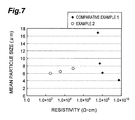
- FIG. 7 is a graph showing the relationship between resistivity and particle size for zinc oxide sintered compacts of the examples and comparative examples.
- FIG. 8 is a graph showing the relationship between wavelength and transmittance for zinc oxide thin-films of the examples and comparative examples.
- ppm zirconium weight-based content, of the total weight (wt ppm).
- FIG. 1 is a perspective view showing a zinc oxide sintered compact according to this embodiment.
- the zinc oxide sintered compact 10 of this embodiment is a sintered compact containing zinc oxide as the major component, with zirconium at 10 to 1000 ppm in addition to zinc oxide.
- the zinc oxide sintered compact (also referred to as “sintered compact”) 10 contains zirconium at a content of at least 10 ppm, and the zirconium can thereby be uniformly present inside the particles and at the grain boundaries of the zinc oxide sintered compact 10 . This can drastically increase the strength of the zinc oxide sintered compact 10 . If the zirconium content is less than 10 ppm, it will be difficult for the zirconium to uniformly diffuse throughout the zinc oxide sintered compact, and it will become difficult to increase the strength of the zinc oxide sintered compact 10 .
- a greater zirconium content will tend to increase the strength of the zinc oxide sintered compact 10 .
- a zirconium content of greater than 1000 ppm will lower the resistivity of a zinc oxide thin-film formed using a sputtering target comprising the sintered compact. The effect of allowing production of a zinc oxide thin-film with high resistance will be reduced as a result.
- the zirconium content of the zinc oxide sintered compact 10 of this embodiment is therefore between 10 and 1000 ppm.
- the zirconium content is preferably 30 to 1000 ppm.
- the zinc oxide sintered compact 10 of this embodiment thus has high strength. It can therefore be used as a cylindrical zinc oxide-based target. It can also be suitably used as a sputtering target.
- the resistivity of the zinc oxide sintered compact 10 of this embodiment is preferably no greater than 10 5 ⁇ cm. Such low resistivity of the zinc oxide sintered compact 10 will allow its use as a sputtering target in a direct current sputtering method. There are no particular restrictions on the method of limiting the resistivity to no greater than 10 5 ⁇ cm.
- the zirconium content of the zinc oxide sintered compact 10 may be set at 500 ppm or greater, or oxygen defects may be created in the zinc oxide to lower the bulk resistance value. When oxygen defects are present in zinc oxide, carriers are generated and the resistivity of the zinc oxide sintered compact 10 is reduced.
- the method for creating oxygen defects is not particularly restricted.
- the oxygen partial pressure in the atmosphere may be lowered during firing of the zinc oxide sintered compact 10 . It will thus be possible to lower the resistivity of the zinc oxide sintered compact 10 to about 1/100 compared to firing in air, even when the zirconium content is less than 500 ppm.
- oxygen deficiency may be compensated by adding a trace amount of oxygen gas.
- the zinc oxide sintered compact 10 containing zirconium may be produced in the following manner, as an example. Specifically, the production method described here has a mixing step in which a powder containing zinc oxide and a zirconium source is prepared, a molding step in which the powder is molded to produce a compact, and a firing step in which the compact is fired. Each step will now be explained in detail.
- the zinc oxide powder starting material used is preferably one with as few impurities as possible, in order to minimize lowering the resistivity of the zinc oxide thin-film.
- the zirconium source that is added is not particularly restricted so long as it contains zirconium, and it may be zirconium metal, a zirconium salt such as zirconium chloride, a zirconium complex, zirconium oxide (zirconia), partially stabilized zirconia, stabilized zirconia, or alumina-added zirconia.
- zirconium oxide Preferred among these zirconium sources are zirconium oxide, partially stabilized zirconia, stabilized zirconia and alumina-added zirconia, which are oxides like zinc oxide.
- a powder When a powder is used as an additive, it is preferably a fine powder in order to improve dispersibility.
- the method for mixing the zinc oxide powder and zirconium source is not particularly restricted.
- the zinc oxide powder and zirconium source are preferably mixed to as uniform a state as possible.
- the mixing method may be a method of dry ball mill mixing, wet bead mill mixing or agitated mixing. Methods in which zinc oxide powder mixed with a prescribed amount of a zirconium source is further mixed with zinc oxide powder, for dilution to a prescribed concentration, are also effective as methods for achieving uniform mixing.
- a different method for adding and mixing a zirconium source is one in which zirconium oxide is used as the medium for the grinding, mixing or dispersing apparatus.
- this method involves using a container with zirconia beads and/or lined with zirconia as the grinding, mixing and dispersing apparatus, for grinding, mixing and dispersion of zinc oxide in order to mix a trace amount of zirconium with the zinc oxide powder.
- This method is advantageous in that it prevents the medium for the grinding, mixing and dispersing apparatus from becoming a contaminating source, and the medium serves as a zirconium source.
- zinc oxide is prepared as a slurry and dispersed with zirconia beads in a zirconia-lined container. This will allow uniform mixing of zirconium and zinc oxide. Using such a method will allow uniform mixing of a trace amount of zirconium with the zinc oxide. The amount of addition may be adjusted by the mixing time, allowing the zirconium content of the final zinc oxide sintered compact 10 to be controlled to between 10 and 1000 ppm.
- the grinding, mixing and dispersing apparatus may be either dry or wet, but it is preferably wet from the viewpoint of obtaining a more uniform dispersed state of the zirconium.
- the final state of the powder is not particularly restricted.
- a granulated powder for molding with a dry system, it is preferred to use a granulated powder so that the powder flow property is high and the compact density is uniform.
- the granulation method is also not particularly restricted, and may be spraying granulation, fluidized bed granulation, tumbling granulation, agitated granulation or the like. Spraying granulation is preferably employed because the procedure is easy and it allows treatment in bulk.
- the BET specific surface area of the powder is preferably 2 to 20 m 2 /g and more preferably 4 to 10 m 2 /g. If the BET specific surface area is lower than 2 m 2 /g, densification of the sintered compact will proceed with greater difficulty, tending to result in low density and reduced strength of the sintered compact. If the BET specific surface area is higher than 20 m 2 /g, on the other hand, the powder will tend to aggregate, thereby hampering molding. In addition, the high sinterability tends to promote grain growth during firing, resulting in coarse particles and reduced strength of the sintered compact.
- the mean secondary particle size of the powder is preferably no greater than 1.5 ⁇ m and more preferably 0.1 to 1.5 ⁇ m, in consideration of the powder moldability and sinterability. Using such a powder can improve the sintered compact density.
- the “secondary particle size” is the particle size for aggregated primary particles as observed by TEM or the like. The secondary particle size can be measured with a wet particle size distribution meter or the like, after suspension of the powder.
- the bulk density of the powder is preferably 0.5 to 1.8 g/cm 3 . Powder with a bulk density within this range will have excellent handleability and high molding yield. In addition, it can increase the density of the obtained zinc oxide sintered compact.
- the angle of repose of the powder is preferably no greater than 45°. A greater value will tend to impair the flow property of the powder, making it difficult to achieve uniform packing of the powder.
- the angle of repose of the powder is more preferably no greater than 35°, from the viewpoint of further improving the powder flow property.
- the method for producing the compact is not particularly restricted, and for example, a die press molding method, cold isostatic press molding method or cast molding method may be used.
- the powder or slurry used as starting material may contain an organic or inorganic binder. Such methods may be used to fabricate compacts of various shapes, such as flat or cylindrical.
- [Firing Step] The obtained compact is formed into a sintered compact by firing at high temperature.
- the production apparatus used to produce the sintered compact is not particularly restricted, and for example, an electric furnace, gas furnace or hot press may be used. Preferred among these is an electric furnace, in terms of productivity, temperature distribution in the furnace and relative low cost of the apparatus.
- zirconium is mixed with zinc oxide at 10 ppm or greater to obtain a dense sintered compact with a relative density of 95% or greater.
- the reason for this is as follows. Specifically, zirconium inhibits firing of zinc oxide during the firing. As a result, since the shrinkage speed during firing is reduced, the particle size of the sintered compact particles is smaller than when no zirconium is present. In addition, the differential shrinkage between the exterior and interior by firing is reduced, leaving fewer air bubbles inside the sintered compact. This yields a high-density sintered compact. Furthermore, addition of zirconium increases the strength of interaction at the grain boundaries, and can inhibit cracking, chipping and shedding at the grain boundaries.
- the firing conditions are not particularly restricted, but from the viewpoint of shortening the firing time and preventing cracking, the temperature-elevating rate is preferably 10° C. to 400° C./hr. From the same viewpoint, the firing temperature is preferably 900° C. to 1200° C. In addition, from the viewpoint of obtaining a dense sintered compact with a relative density of 97% or greater, the firing temperature is preferably 950° C. to 1150° C.
- the temperature-lowering rate is preferably 10° C. to 400° C./hr from the viewpoint of preventing cracking.
- the temperature when the sintered compact is removed from the furnace is preferably close to room temperature.
- a higher density of the zinc oxide sintered compact can increase the strength.
- the relative density is therefore preferably 95% or greater and more preferably 97% or greater.
- a smaller particle size for the particles composing the zinc oxide sintered compact will increase the strength.
- the mean particle size of the particles of the zinc oxide sintered compact is preferably 1-15 ⁇ m and more preferably 1-10 ⁇ m.
- the hardness of the sintered compact is preferably 120HV10 or greater and more preferably 150HV10 or greater, in terms of Vickers hardness. Such a sintered compact will exhibit increased strength.
- the target In order to prevent cracking of the target during sputtering, the target must have higher strength than the thermal stress generated in the target during sputtering. The thermal stress will differ depending on the sputtering conditions and sputter apparatus, but will generally be about 40 Mpa. Therefore, in order to prevent cracking of the target during sputtering, the target must have a strength, i.e. transverse intensity, that is greater than this level.
- the zinc oxide sintered compact 10 of this embodiment As the target, it is possible to obtain a target transverse intensity of 40 MPa or greater. This can adequately inhibit cracking and chipping of the sintered compact during firing and sintered compact machining, and will allow increased yield to be obtained. It will also make it possible to minimize defects (pinholes) in the substrate that are caused by anomalous discharge resulting from cracking of the target during sputtering. This will allow stable film formation, so that a zinc oxide thin-film can be produced at high yield.
- zirconium generates carrier electrons, lowering the resistivity of the sintered compact.
- firing at high temperature results in a resistivity of 10 5 ⁇ cm or lower.
- the target can therefore be suitably used as a target for a direct current sputtering method.
- the resistivity of the zinc oxide sintered compact 10 is preferably lowered still further.
- an inert gas or nitrogen gas is introduced into the firing furnace to lower the oxygen partial pressure in the firing atmosphere, and the zinc oxide compact is fired in that state.
- the resistivity of the sintered compact will be no greater than 10 5 ⁇ cm even if the firing temperature is 1100° C. or below.
- the zinc oxide sintered compact 10 of this embodiment can be used as a sputtering target.
- the zinc oxide sintered compact 10 may be machined to prescribed dimensions.
- the machining method is not particularly restricted, and for example, a surface grinding method, rotary grinding method or cylindrical grinding method may be employed. Since the zinc oxide sintered compact 10 of this embodiment contains a prescribed amount of zirconium, the particle size of the sintered compact is small and the grain boundary strength is increased. At the same time, the sintered compact is densified and the hardness of the sintered compact is increased. Cracking and chipping therefore occur less frequently during polishing of the sintered compact to the prescribed target dimensions. As a result, the yield during production of sputtering targets is increased.
- the zinc oxide sintered compact 10 of this embodiment, and the zinc oxide sintered compact 20 described below, may if necessary be anchored (bonded) to a flat or cylindrical support using a bonding agent such as a solder material.
- the material of the support is not particularly restricted so long as it has high thermal conductivity and strength capable of supporting the sintered compact.
- the material of the support is preferably a metal such as Cu (copper), SUS (stainless steel) or Ti (titanium), for high thermal conductivity and high strength, and more preferably Ti (titanium) because it has a coefficient of thermal expansion close to that of zinc oxide.
- FIG. 2 is a perspective view showing another embodiment of a zinc oxide sintered compact of the invention.
- the zinc oxide sintered compact 20 may have a flat shape, as shown in FIG. 2 .
- the shape of the support is cylindrical when the zinc oxide sintered compact is cylindrical as shown in FIG. 1 .
- a flat support is used.
- the adhesive material (bonding material) used to bond the sintered compact and the support is not particularly restricted so long as it has sufficient bonding strength for support, and for example, a conductive resin, tin-based solder material or indium-based solder material may be used. Of these, indium solder is preferred because it has high conductivity and thermal conductivity, and is soft and easily deformed. The reason for this is to allow efficient cooling of the heat on the target surface, and to allow absorption of the stress between the sintered compact and the support that is generated by thermal expansion to prevent cracking of the sintered compact.
- the support undergoes little expansion because it is being cooled by cooling water.
- the sputtering target expands by the heat generated by sputtering, regardless of its shape.
- a flat target such as shown in FIG. 2
- the distance between the target and the support does not change.
- a cylindrical target such as shown in FIG. 1
- the distance between the target and the support increases due to thermal expansion of the target. Therefore, force is applied perpendicular to the interface between the sintered compact and the adhesive material, increasing detachment from the air bubble sections and lowering the heat conduction, with targets that have a low bonding rate. Consequently, a cylindrical target with a low bonding rate tends to result in more cracking than a flat target.
- the bonding rate is preferably at least 90% from the viewpoint of preventing cracking.
- the bonding rate is preferably at least 95% and more preferably at least 97%, from the same viewpoint.
- the zinc oxide sintered compacts 10 , 20 have higher strength than common high-purity zinc oxide sputtering targets. Stress between the sintered compact 10 and the support, generated by thermal expansion during bonding of the cylindrical sintered compact 10 , can therefore be adequately withstood. It is thus possible to produce a sputtering target at high yield.
- the sputtering target of this embodiment (also referred to simply as “target”) comprises the aforementioned zinc oxide sintered compact, and the zinc oxide sintered compact may be used directly or machined for use in sputtering.
- the sputtering target of this embodiment may have either the cylindrical or flat shape shown in FIG. 1 or FIG. 2 .
- the sputtering target of this embodiment also has the same composition as the zinc oxide sintered compact described above.
- the sputtering target of this embodiment comprises the zinc oxide sintered compact described above, it has high density and high grain boundary strength. During sputtering, therefore, cracking of the target does not easily occur and particle generation is minimal. It is also possible to inhibit generation of black protrusion-like matter (nodules) that takes place on the target surface during sputtering. Furthermore, the high density results in high thermal conductivity, and also resistance to cracking by thermal stress even with application of high power to the target. Therefore, defects (pinholes) in the substrate can be reduced during production of a zinc oxide thin-film by sputtering. As a result, in addition to the high yield, the target can be used for prolonged periods.
- the zinc oxide thin-film of this embodiment (also referred to simply as “thin-film”) is obtained using the sputtering target described above.
- the zinc oxide thin-film therefore has the same composition as the sputtering target (zinc oxide sintered compact). That is, by forming a film using a sputtering target made of a zinc oxide sintered compact containing zinc oxide as the major component and having a zirconium content of 10 to 1000 ppm, it is possible to obtain a zinc oxide thin-film having a zirconium content that is approximately equal to that of the sputtering target.
- the zinc oxide thin-film of this embodiment has a zirconium content of 10 to 2000 ppm, and high resistivity of 10 ⁇ cm or greater.
- the method for producing the zinc oxide thin-film of this embodiment includes chemical vapor deposition methods such as CVD, methods of suspending or dissolving it in a solvent for coating, and methods of film formation by sputtering or the like. Sputtering is preferred among these methods.
- the sputtering target used for sputtering may be a zinc oxide sintered compact produced with a prescribed concentration of zirconium.
- a zinc oxide thin-film may also be formed by sputtering using a zinc oxide target with zirconium on-chip.
- a zinc oxide thin-film with a zirconium content of 10 to 1000 ppm can be obtained by sputtering the sputtering target described above.
- the zinc oxide thin-film of this embodiment has high resistivity, because it contains zirconium at 10 ppm or greater. High resistivity is also exhibited up to a zirconium concentration of about 1000 ppm. Exceeding approximately 1000 ppm, however, results in drastically reduced resistivity. Nevertheless, high resistivity of 10 ⁇ cm or greater, necessary for use as a highly resistant film layer for a solar cell such as a CIGS, is maintained until 2000 ppm is exceeded. The zinc oxide thin-film of this embodiment must therefore have its zirconium content limited to no greater than 2000 ppm. In order to obtain a zinc oxide thin-film with a sufficiently high resistance value, as shown in FIG. 5 , the upper limit is 1000 ppm, as the region in which the resistance value begins to fall, and the zirconium content is between 10 and 1000 ppm.
- the resistance value increases at about 10 ppm or greater and then falls at about 1000 ppm or greater, when the zirconium content is increased in this manner. It is considered likely that the locations where zirconium is present vary depending on the zirconium content, resulting in inhibition or increase in the conductivity of the thin-film, and that the threshold values for this variation are near 10 ppm and 1000 ppm.
- the change in resistivity of a thin-film due to the sputtering conditions is not very significant up to a zirconium content of about 1000 ppm.
- a zirconium content of 1200 ppm or greater can potentially lower the resistivity of a thin-film in sputtering with argon gas alone. Therefore, by introducing a small amount of oxygen gas during sputtering, it is possible to inhibit carrier generation and increase the resistance value of the thin-film.
- Oxygen gas may also be introduced during sputtering even if the zirconium content is between 10 and 1000 ppm. The aforementioned effect is obtained if the amount of oxygen gas introduced is at least 0.2 vol % with respect to the amount of argon gas introduced. From the viewpoint of obtaining a thin-film with even higher resistance, the amount of oxygen gas introduced is preferably at least 0.4 vol %.
- the zinc oxide thin-film of this embodiment has high transmittance since carrier generation is adequately inhibited by zirconium.
- very high transmittance such as transmittance of 75% or greater, can be achieved not only at a wavelength of 500 nm but also across a wide range of 400 to 1200 nm. It is therefore suitable for use as a buffer layer or the like in a thin-film solar cell.
- the shape of the zinc oxide sintered compact is not limited to the shapes shown in FIG. 1 and FIG. 2 , and may instead be another shape.
- the BET specific surface area of the powder was measured by the single-point BET method, using a MONOSORB (trade name of Quantachrome, USA).
- the bulk density of the powder was measured according to the light bulk density measurement method specified in JIS R9301-2-3.
- the powder was suspended in water and subjected to ultrasonic dispersion for 2 minutes, and then a COULTER LS (trade name of Beckman Coulter, Inc.) was used to measure the particle size distribution. The median diameter was calculated from the measurement results and recorded as the mean secondary particle size. (Measurement of Angle of Repose of Powder) The angle of repose, as a parameter of the powder flow property, was measured using a Model PT-N Powder Tester by Hosokawa Micron Group.
- the true density of the sintered compact was assumed to be 5.68 g/cm 3 , as the density of zinc oxide.
- the zirconium content was measured by ICP analysis, after dissolution of each target of the measurement.
- Resistivity of Sintered Compact and Thin-Film A HIRESTA MCP-HT450 measuring apparatus (trade name of Mitsubishi Chemical Corp.) was used to detect the current value upon 1 minute application of a voltage of 10-1000 V, and the surface resistance was calculated.
- LORESTA HP MCP-T410 (trade name of Mitsubishi Chemical Corp.) was used and the four-point probe method was performed with application of a constant current of 1 mA to 100 mA.
- Transmittance of Thin-Film The light transmittance of the integrated body of the substrate and thin-film was measured using a U-4100 spectrophotometer (trade name of Hitachi, Ltd.), at a wavelength in the range of 240 nm to 2600 nm.
- a 600 g portion of the obtained powder was loaded into a 150 mm ⁇ die and subjected to pressure molding at 300 kgf/cm 2 (29.42 MPa), to obtain a disc-shaped compact.
- a total of three compacts were produced in the same manner.
- the three compacts were subjected to CIP treatment at 3000 kgf/cm 2 (294.2 MPa).
- each compact was heated to 500° C. at 50° C./h, and then from 500° C. to 1100° C. at a temperature-elevating rate of 20° C./h. After holding at a firing temperature of 1100° C. for 3 hours, it was cooled at a temperature-lowering rate of 100° C./h.
- the firing was conducted in an air atmosphere.
- the firing conditions are shown in Table 2.
- the success rates up to firing and target fabrication are also shown in Table 2.
- “success rate” means the proportion of sintered compacts and targets successfully fabricated without cracking or chipping.
- the relative density, transverse intensity, Vickers hardness, mean particle size, resistivity and zirconium content of each obtained sintered compact are shown in Table 3.
- the values shown in Table 3 are the average values for the three sintered compacts. The three compacts were all successfully fired without cracking (success rate: 100%).
- the three sintered compacts were then each worked into a disc shape with a diameter of 101.6 mm ⁇ and a thickness of 5 mm.
- the disc-shaped sintered compacts were bonded to a copper backing plate to fabricate three zinc oxide targets (sputtering targets).
- the bonding material used was In (indium) solder.
- Film-forming apparatus ULVAC CS2000 (trade name, magnetron sputtering apparatus)
- Zinc oxide thin-film thickness Approximately 100 nm
- Substrate temperature Room temperature (approximately 25° C.)
- the resistivity of the zinc oxide thin-film obtained by sputtering was a high value of 5.5 ⁇ 10 6 ⁇ cm.
- the transmittance of the zinc oxide thin-film was 86% at a wavelength of 500 nm of transmitted light through a 100 nm film thickness.
- the zirconium content of the zinc oxide thin-film was 40 ppm zirconium, as shown in Table 4. This confirmed that using a high-strength zinc oxide-based sputtering target can produce a zinc oxide-based high-resistance thin-film.
- a compact was produced in the same manner Example 1, except that the mixing ratio of the zinc oxide powder and zirconium oxide powder was changed, for zirconium contents of 20 ppm, 45 ppm and 1000 ppm. Three samples each of the three compacts with different zirconium contents (Nos. 2, 3 and 4 in Table 1) were produced. The physical properties of the size-adjusted mixed powder are shown in Table 1.
- Each compact was heated to 500° C. at 50° C./h, and then from 500° C. to 1100° C. at a temperature-elevating rate of 20° C./h, and held at a firing temperature of 1100° C. for 3 hours. The temperature was then lowered at a temperature-lowering rate of 100° C./h to obtain a zinc oxide sintered compact.
- the firing was conducted in a nitrogen gas atmosphere, under conditions with a gas flow parameter of 1.8. The firing conditions are shown in Table 2. The success rate up to firing was 100% for all of sample Nos. 2 to 4, as seen in Table 2.
- the physical properties of the sintered compacts were as shown in Table 3. It was thus confirmed that sintered compacts with high relative density, high transverse intensity, high Vickers hardness and low resistivity had been obtained.
- the obtained zinc oxide targets were used for film formation under the following conditions, and the obtained zinc oxide thin-films were evaluated.
- Discharge system Direct current sputtering method
- Film-forming apparatus ULVAC CS2000 (trade name, magnetron sputtering apparatus)
- Zinc oxide thin-film thickness Approximately 100 nm
- Substrate temperature Room temperature (approximately 25° C.)
- the physical properties of the zinc oxide thin-films obtained by sputtering were as shown in Table 4. As shown in Table 4, zinc oxide thin-films with high resistance value and high transmittance were obtained. These results confirmed that a sputtering target with both high strength and low resistivity, containing zirconium at 18 to 990 ppm, can be fabricated at high yield. Specifically, it was confirmed that a zinc oxide-based thin-film with higher resistivity can be produced by a direct current sputtering method.
- a commercially available zinc oxide powder (15 kg) satisfying the JIS Class 1 standard was mixed with purified water to prepare a slurry.
- the slurry with a zinc oxide powder concentration of 50 wt % was dispersed using a wet bead mill apparatus.
- the apparatus container was made of zirconia, and the beads used were 0.3 mm zirconia beads.
- the slurry treated with the wet bead mill apparatus was collected and subjected to spraying granulation. Since the amount of zirconium addition can be increased by lengthening the grinding time in the wet bead mill apparatus, three powders with different zirconium contents were prepared by varying the grinding time. The zirconium contents of the prepared powders were 15 ppm, 33 ppm and 120 ppm, respectively. The physical properties of each powder were as shown in Table 1, and the obtained powders had high flow properties.
- a 600 g portion of each obtained powder was loaded into a 150 mm ⁇ diameter die and subjected to pressure molding at 300 kgf/cm 2 (29.42 MPa). Three compacts each were produced from mixed powders with different zirconium contents (Nos. 5, 6 and 7 in Table 1). After pressure molding, CIP treatment was carried out at 3000 kgf/cm 2 (294.2 MPa) to increase the compact density.
- Each compact was heated to 500° C. at 50° C./h, and then from 500° C. to 1100° C. at a temperature-elevating rate of 10° C./h, and held at a firing temperature of 1100° C. for 3 hours. It was then cooled at a temperature-lowering rate of 100° C./h to obtain a zinc oxide sintered compact.
- the firing was conducted in a nitrogen gas atmosphere, under conditions with a gas flow parameter of 1.0. The firing conditions are shown in Table 2. The success rate up to firing was 100% under each of the conditions, as seen in Table 2.
- the physical properties of the sintered compacts were as shown in Table 3, and it was confirmed that sintered compacts with high relative density, high transverse intensity, high Vickers hardness and high resistivity could be obtained at high yield.
- each of the obtained zinc oxide sintered compacts was used for bonding in the same manner as Example 1, to obtain a zinc oxide target.
- the success rate up to firing was 100%.
- Each of the obtained zinc oxide targets was used for film formation under the same conditions as Example 2 to form a zinc oxide thin-film, which was evaluated.
- the resistivity and transmittance of each zinc oxide thin-film obtained by sputtering were as shown in Table 4, and it was possible to produce high resistance zinc oxide thin-films with high transmittance.
- the same powder was prepared as the powder prepared for No. 6 in Example 3.
- the powder was packed into a cylindrical rubber die and subjected to CIP molding at 2000 kgf/cm 2 (196.133 MPa).
- CIP treatment was carried out at 3000 kgf/cm 2 (294.2 MPa) to increase the density. Two cylindrical compacts were thus produced. No cracking had occurred in these compacts.
- the obtained compacts were heated to 500° C. at 50° C./h, and then from 500° C. to 1100° C. at a temperature-elevating rate of 10° C./h, and held at a firing temperature of 1100° C. for 3 hours. It was then cooled at a temperature-lowering rate of 100° C./h to obtain a zinc oxide sintered compact.
- the firing was conducted in a nitrogen gas atmosphere, under conditions with a gas flow parameter of 1.0.
- the relative density of each sintered compact was 98.0%.
- the Vickers hardness was 175HV10.
- the sintered compact resistivity was 8.2 ⁇ 10 3 ⁇ cm.
- the zirconium content in the sintered compacts was 33 ppm.
- the mean particle size of the sintered compact particles was 7.0 ⁇ m.
- each sintered compact was machined into a cylindrical shape with an inner diameter of 77.5 mm ⁇ , an outer diameter of 91.5 mm ⁇ and a thickness of 350 mm, and bonded onto a titanium backing tube to obtain a cylindrical zinc oxide target without cracking or chipping.
- the bonding material used was In solder.
- the obtained targets were used for film formation under the following conditions, to form zinc oxide thin-films.
- the obtained zinc oxide thin-films were evaluated. The evaluation results were as shown in Table 4.
- Zinc oxide thin-film thickness Approximately 100 nm
- Substrate temperature Room temperature
- the resistance of each zinc oxide thin-film obtained by sputtering was a high value of 5.0 ⁇ 10 5 ⁇ cm.
- the transmittance was 86% at a wavelength of 500 nm through a 100 nm film thickness.
- Powder containing zirconium was prepared in the same manner as Example 3, and a compact was produced in the same manner as Example 3. Three compacts each were produced with three different compositions (Nos. 9, 10 and 11 in Table 1), in the same manner as Example 3.
- each of the obtained zinc oxide sintered compacts was used for bonding in the same manner as Example 1, to obtain a zinc oxide target.
- the success rate up to firing was 100%.
- the obtained zinc oxide targets were used for film formation under the same conditions as Example 2 to form zinc oxide thin-films, and the thin-films were evaluated.
- the evaluation results were as shown in Table 4.
- the resistivity of each zinc oxide thin-film obtained by sputtering was a high value of 3.0 ⁇ 10 5 ⁇ cm.
- the transmittance was a high value of 86% for a wavelength of 500 nm through a 100 nm film thickness.
- the zirconium content was 65 ppm.
- Powder was prepared by the same method as Example 1, except that no zirconium was added to the commercially available zinc oxide powder satisfying the JIS Class 1 standard.
- the physical properties of the powder were as shown in Table 1.
- a 600 g portion of the prepared powder was loaded into a 150 mm ⁇ diameter die and subjected to pressure molding at 300 kgf/cm 2 (29.42 MPa), to produce three compacts for each of Nos. 12-15 in Table 1.
- CIP treatment was carried out at 3000 kgf/cm 2 (294.2 MPa) to increase the compact density.
- the compact was heated to 500° C. at 50° C./h, and then from 500° C. to the firing temperature at a temperature-elevating rate of 20° C./h, and held at a firing temperature of 950° C., 1000° C., 1100° C. or 1200° C. for 3 hours. It was then cooled at a temperature-lowering rate of 100° C./h to obtain a sintered compact.
- the firing was conducted in air.
- the firing conditions are shown in Table 2. Three compacts were fired at each firing temperature to produce zinc oxide sintered compacts, and as shown by the “Success rate up to firing” in Table 2, some cracking occurred during firing with sample Nos. 14 and 15. This is presumably due to reduced strength, as seen by the transverse intensities shown in Table 3.
- each obtained zinc oxide sintered compact was used for bonding in the same manner as Example 1, to obtain a zinc oxide target. Because cracking occurred during machining, the success rate up to zinc oxide target fabrication was reduced, as shown in Table 2.
- Each of the obtained zinc oxide targets was used for RF sputtering film formation under the same conditions as Example 1 to form a zinc oxide thin-film, and the thin-film was evaluated.
- the evaluation results were as shown in Table 4.
- the resistivity of each zinc oxide thin-film obtained by sputtering was a value between 1.0 ⁇ 10 5 and 1.2 ⁇ 10 6 ⁇ cm.
- the transmittance was 86% to 87% at a wavelength of 500 nm through a 100 nm film thickness.
- Powder was prepared by the same method as Comparative Example 1, and molding was performed to produce three compacts. Each compact was heated to 500° C. at 50° C./h, and then from 500° C. to 1170° C. at a temperature-elevating rate of 10° C./h, and held at a firing temperature of 1170° C. for 3 hours. It was then cooled at a temperature-lowering rate of 100° C./h to obtain a zinc oxide sintered compact.
- the firing conditions are shown in Table 2. The firing was conducted in a nitrogen gas atmosphere, under conditions with a gas flow parameter of 1.0.
- each of the obtained zinc oxide sintered compacts was used for bonding in the same manner as Example 1, to obtain a zinc oxide target. Because cracking occurred during machining, the success rate up to target fabrication was reduced, as shown in Table 2.
- Each of the obtained zinc oxide targets was used for film formation under the same conditions as Example 2 to form a zinc oxide thin-film, which was evaluated.
- the evaluation results were as shown in Table 4.
- the resistivity of each zinc oxide thin-film obtained by sputtering was 1.2 ⁇ 10 5 ⁇ cm.
- the transmittance was 86% at a wavelength of 500 nm through a 100 nm film thickness.
- Powder was prepared in the same manner as Comparative Example 1, except that the amount of powder prepared was 15 kg.
- the powder was packed into a cylindrical rubber die and subjected to CIP molding at 2000 kgf/cm 2 (196.133 MPa), and then further CIP treatment at 3000 kgf/cm 2 (294.2 MPa) to increase the density, producing two cylindrical compacts.
- Each produced compact was heated to 500° C. at 50° C./h, and then from 500° C. to 1170° C. at a temperature-elevating rate of 10° C./h, and held at a firing temperature of 1170° C. for 3 hours. It was then cooled at a temperature-lowering rate of 100° C./h to obtain a zinc oxide sintered compact.
- the firing was conducted in a nitrogen gas atmosphere, under conditions with a gas flow parameter of 1.0.
- the firing conditions are shown in Table 2.
- the evaluation results for the zinc oxide sintered compacts are shown in Table 3, and they were a relative density of 96.3%, a Vickers hardness of 110HV10 and a resistivity of 8.0 ⁇ 10 4 ⁇ cm.
- Each obtained sintered compact was machined into a cylindrical shape with an inner diameter of 77.5 mm ⁇ , an outer diameter of 91.5 mm ⁇ and a thickness of 350 mm, and bonding was attempted, but cracking occurred during the machining and bonding and it was not possible to fabricate a target.
- Each compact was heated to 500° C. at 50° C./h, and then from 500° C. to 1100° C. at a temperature-elevating rate of 20° C./h, and held at a firing temperature of 1100° C. for 3 hours. It was then cooled at a temperature-lowering rate of 100° C./h to obtain a zinc oxide sintered compact.
- the firing was conducted in a nitrogen gas atmosphere, under conditions with a gas flow parameter of 1.0. The firing conditions are shown in Table 2.
- the success rates up to firing were as shown in Table 2.
- the physical properties of the sintered compacts were as shown in Table 3. With a low zirconium content, the zinc oxide sintered compact strength was low and cracking occurred during firing.
- each of the obtained zinc oxide sintered compacts was used for bonding in the same manner as Example 1, to obtain a zinc oxide target.
- the obtained zinc oxide targets were used for film formation under the same conditions as Example 2 to form zinc oxide thin-films, and the thin-films were evaluated.
- the physical properties of the zinc oxide thin-films obtained by sputtering were as shown in Table 4. With a high zirconium content, the resistivity was lowered and it was not possible to produce a zinc oxide film with a high resistance value.
- FIG. 3 is a graph showing the relationship between the zirconium contents of the zinc oxide sintered compacts and the transverse intensities of the sintered compacts of Example 2, Example 3, Example 4 and Comparative Example 4, which were fired in a nitrogen gas atmosphere.
- the graph shows that a higher zirconium content results in increased sintered compact strength. Also, a low zirconium content (less than about 10 ppm) resulted in drastically reduced strength. It can be read from the graph that the sintered compact strength increases from around 10 ppm. In other words, with a zirconium content of 10 ppm or greater it is possible to obtain a zinc oxide sintered compact with increased strength.
- FIG. 4 is a graph showing the relationship between zirconium contents in the zinc oxide sintered compacts and resistivities of the zinc oxide thin-films, for Example 2, Example 3, Comparative Example 2 and Comparative Example 4, wherein the films were formed by direct current sputtering.
- a zirconium content exceeding about 1000 ppm significantly lowers the thin-film resistivity.
- limiting the zirconium content to no greater than 1000 ppm can maintain high resistivity for zinc oxide thin-films.
- FIG. 5 is a graph showing the relationship between zirconium contents in the zinc oxide thin-films and resistivities of the zinc oxide thin-films, for Example 2, Example 3, Comparative Example 2 and Comparative Example 4, wherein the films were formed by direct current sputtering.
- a zirconium content exceeding about 1000 ppm significantly lowers zinc oxide thin-film resistivity.
- high resistivity of at least 10 ⁇ cm is exhibited up to at least 2000 ppm, the resistivity is drastically lowered when this is exceeded.
- FIG. 6 is a graph showing the relationship between the resistivities and transverse intensities of the sintered compacts of Example 2 and Comparative Example 1.
- Example 2 contains zirconium, and Comparative Example 1 does not contain zirconium.
- Comparative Example 1 when no zirconium is present, lowering the resistivity of the sintered compact lowers the transverse intensity. In other words, it is not possible to increase the transverse intensity of a sintered compact while lowering the resistance.
- a suitable amount of zirconium as in Example 2 it is possible to obtain both low resistance of no greater than 10 5 ⁇ cm and high transverse intensity of at least 40 MPa.
- adding a suitable amount of zirconium makes it possible to fabricate a sputtering target with higher transverse intensity and lower resistivity than a conventional thin-film sputtering target that has high resistivity.
- FIG. 7 is a graph showing the relationship between the resistances of the sintered compacts of Example 2 and Comparative Example 1, and the mean particle sizes of the particles of the sintered compacts.
- a conventional sintered compact will have a larger mean particle size of particles of the sintered compact as the resistance value of the sintered compact decreases, as understood from Comparative Example 1.
- adding a suitable amount of zirconium can inhibit enlargement of the sintered compact particles even when the resistance value of the sintered compact is reduced.
- This relationship also contributes to the relationship shown in FIG. 6 , and smaller sintered compact particles result in increased transverse intensity of a sintered compact. Adding zirconium, therefore, can inhibit growth of sintered compact particles, while zirconium imparts suitable conductivity, thereby reducing the resistivity of the sintered compact.
- FIG. 8 is a graph showing the transmittance of zinc oxide thin-film No. 6 of Example 3. The light wavelength is shown on the abscissa, and the relevant transmittance is shown on the ordinate. It is seen that high transmittance was exhibited across a wide wavelength range.
- the invention it is possible to prevent cracking and chipping from occurring while bonding during firing, sintered compact machining and target fabrication, and to improve productivity for sputtering targets. It is also possible to adequately inhibit cracking of targets during sputtering, and allow stable production of a zinc oxide thin-film with both high resistivity and high transmittance. There is also provided a zinc oxide thin-film with high resistivity, that can be suitably used in a semiconductor insulating film or a buffer layer for a solar cell.
Landscapes
- Chemical & Material Sciences (AREA)
- Engineering & Computer Science (AREA)
- Ceramic Engineering (AREA)
- Materials Engineering (AREA)
- Organic Chemistry (AREA)
- Manufacturing & Machinery (AREA)
- Structural Engineering (AREA)
- Chemical Kinetics & Catalysis (AREA)
- Mechanical Engineering (AREA)
- Metallurgy (AREA)
- Inorganic Chemistry (AREA)
- Physical Vapour Deposition (AREA)
- Compositions Of Oxide Ceramics (AREA)
- Formation Of Insulating Films (AREA)
- Non-Insulated Conductors (AREA)
- Crystallography & Structural Chemistry (AREA)
Abstract
Description
- [PTL 1] Japanese Unexamined Patent Application Publication HEI No. 2-149459
- [PTL 2] International Patent Publication No. WO2009/110092
- [PTL 3] Japanese Unexamined Patent Application Publication No. 2009-167095
- [PTL 4] Japanese Patent Public Inspection SHO No. 58-500174
- [PTL 5] Japanese Unexamined Patent Application Publication No.
[Firing Step]
The obtained compact is formed into a sintered compact by firing at high temperature. The production apparatus used to produce the sintered compact is not particularly restricted, and for example, an electric furnace, gas furnace or hot press may be used. Preferred among these is an electric furnace, in terms of productivity, temperature distribution in the furnace and relative low cost of the apparatus.
Gas flow rate parameter=B/A
bonding rate=(area to be bonded−void area)/area to be bonded×100
(Measurement of Angle of Repose of Powder)
The angle of repose, as a parameter of the powder flow property, was measured using a Model PT-N Powder Tester by Hosokawa Micron Group.
(Mean Particle Size of Sintered Compact Particles)
After polishing the sintered compact, it is etched with acetic acid and the etching surface is observed using a SEM (scanning electron microscope) at 100-10,000× magnification, and the mean particle size of the particles is measured by the chord method.
(Vickers Hardness of Sintered Compact)
The Vickers hardness of the sintered compact was measured with an HV10, according to JIS R-1610.
(Transverse Intensity of Sintered Compact)
The transverse intensity of the sintered compact was measured according to JIS R-1601.
(Density of Sintered Compact)
The density of the sintered compact was measured by Archimedes' method. The relative density was calculated from the measured density and the true density of the sintered compact. The true density of the sintered compact was assumed to be 5.68 g/cm3, as the density of zinc oxide.
(Zirconium Content of Powder, Sintered Compact and Thin-Film)
The zirconium content was measured by ICP analysis, after dissolution of each target of the measurement.
(Resistivity of Sintered Compact and Thin-Film)
A HIRESTA MCP-HT450 measuring apparatus (trade name of Mitsubishi Chemical Corp.) was used to detect the current value upon 1 minute application of a voltage of 10-1000 V, and the surface resistance was calculated. For samples that could not be measured with the HERESTA, a LORESTA HP MCP-T410 (trade name of Mitsubishi Chemical Corp.) was used and the four-point probe method was performed with application of a constant current of 1 mA to 100 mA.
(Transmittance of Thin-Film)
The light transmittance of the integrated body of the substrate and thin-film was measured using a U-4100 spectrophotometer (trade name of Hitachi, Ltd.), at a wavelength in the range of 240 nm to 2600 nm.
| TABLE 1 | |||||||
| Mean | |||||||
| secondary | Specific | ||||||
| Zirconium | Bulk | particle | Repose | surface | |||
| content | density | size | angle | area | |||
| No. | (ppm) | (g/cm3) | (μm) | (°) | (m2/g) | ||
| Example 1 | 1 | 45 | 1.0 | 0.3 | 43 | 4.1 |
| Example 2 | 2 | 20 | 1.0 | 0.4 | 43 | 4.2 |
| 3 | 45 | 1.0 | 0.3 | 41 | 4.2 | |
| 4 | 1000 | 1.1 | 0.4 | 44 | 4.1 | |
| Example 3 | 5 | 20 | 1.3 | 0.1 | 32 | 5.4 |
| 6 | 33 | 1.5 | 0.1 | 31 | 6.5 | |
| 7 | 120 | 1.7 | 0.1 | 32 | 8.5 | |
| Example 4 | 8 | 33 | 1.5 | 0.1 | 31 | 6.5 |
| Example 5 | 9 | 33 | 1.5 | 0.1 | 31 | 6.5 |
| 10 | 33 | 1.5 | 0.1 | 31 | 6.5 | |
| 11 | 33 | 1.5 | 0.1 | 31 | 6.5 | |
| Comp. Ex. 1 | 12 | 0 | 1.0 | 0.4 | 41 | 4.1 |
| 13 | 0 | 1.0 | 0.4 | 41 | 4.1 | |
| 14 | 0 | 1.0 | 0.4 | 41 | 4.1 | |
| 15 | 0 | 1.0 | 0.4 | 41 | 4.1 | |
| Comp. Ex. 2 | 16 | 0 | 1.0 | 0.3 | 42 | 4.1 |
| Comp. Ex. 3 | 17 | 0 | 1.0 | 0.4 | 41 | 4.1 |
| Comp. Ex. 4 | 18 | 5 | 1.0 | 0.4 | 43 | 4.1 |
| 19 | 1100 | 1.0 | 0.4 | 43 | 4.1 | |
| 20 | 3000 | 1.0 | 0.3 | 43 | 4.3 | |
| 21 | 8000 | 1.0 | 0.4 | 45 | 4.1 | |
| TABLE 2 | |||||||
| Firing | Success rate | Success rate up | |||||
| temperature | Firing | Gas flow | up to firing | to target | |||
| No. | (° C.) | atmosphere | parameter | (%) | fabrication (%) | ||
| Example 1 | 1 | 1100 | Air | — | 100 | 100 |
| Example 2 | 2 | 1100 | Nitrogen | 1.8 | 100 | 100 |
| 3 | 1100 | Nitrogen | 1.8 | 100 | 100 | |
| 4 | 1100 | Nitrogen | 1.8 | 100 | 100 | |
| Example 3 | 5 | 1100 | Nitrogen | 1.0 | 100 | 100 |
| 6 | 1100 | Nitrogen | 1.0 | 100 | 100 | |
| 7 | 1100 | Nitrogen | 1.0 | 100 | 100 | |
| Example 4 | 8 | 1100 | Nitrogen | 1.0 | 100 | 100 |
| Example 5 | 9 | 900 | Nitrogen | 1.0 | 100 | 100 |
| 10 | 1000 | Nitrogen | 1.0 | 100 | 100 | |
| 11 | 1170 | Nitrogen | 1.0 | 100 | 100 | |
| Comp. Ex. 1 | 12 | 950 | Air | — | 100 | 66 |
| 13 | 1000 | Air | — | 100 | 66 | |
| 14 | 1100 | Air | — | 66 | 33 | |
| 15 | 1200 | Air | — | 66 | 33 | |
| Comp. Ex. 2 | 16 | 1170 | Nitrogen | 1.0 | 100 | 66 |
| Comp. Ex. 3 | 17 | 1170 | Nitrogen | 1.0 | 50 | 0 |
| Comp. Ex. 4 | 18 | 1100 | Nitrogen | 1.0 | 66 | 66 |
| 19 | 1100 | Nitrogen | 1.0 | 100 | 100 | |
| 20 | 1100 | Nitrogen | 1.0 | 100 | 100 | |
| 21 | 1100 | Nitrogen | 1.0 | 100 | 100 | |
| TABLE 3 | ||||||||
| Transverse | Vickers | Mean size | Relative | Zirconium | ||||
| intensity | hardness | Resistivity | of particles | density | content | |||
| No. | (MPa) | (HV10) | (Ω · cm) | (μm) | (%) | (ppm) | ||
| Example 1 | 1 | 110 | 170 | 2.0 × 10⁶ | 7.2 | 97.8 | 45 |
| Example 2 | 2 | 62 | 140 | 7.8 × 10⁴ | 8.0 | 98.0 | 18 |
| 3 | 122 | 170 | 3.8 × 10³ | 7.2 | 98.1 | 45 | |
| 4 | 160 | 190 | 3.2 × 10³ | 6.8 | 98.0 | 990 | |
| Example 3 | 5 | 65 | 175 | 5.3 × 10⁴ | 8.2 | 98.0 | 15 |
| 6 | 130 | 185 | 8.2 × 10³ | 7.0 | 98.2 | 33 | |
| 7 | 150 | 200 | 3.4 × 10³ | 6.7 | 98.5 | 120 | |
| Example 4 | 8 | 130 | 175 | 8.2 × 10³ | 7.0 | 98.0 | 33 |
| Example 5 | 9 | 180 | 220 | 2.3 × 10⁴ | 3.5 | 98.1 | 33 |
| 10 | 160 | 190 | 6.5 × 10³ | 6.5 | 98.6 | 33 | |
| 11 | 50 | 120 | 4.2 × 10³ | 15 | 97.6 | 33 | |
| Comp. Ex. 1 | 12 | 120 | 207 | 5.8 × 10⁹ | 5.2 | 99.1 | 1 |
| 13 | 80 | 147 | 1.0 × 10⁸ | 7 | 98.4 | 1 | |
| 14 | 35 | 115 | 5.1 × 10⁷ | 9.3 | 98.3 | 1 | |
| 15 | 24 | 110 | 3.2 × 10⁷ | 17 | 96.5 | 1 | |
| Comp. Ex. 2 | 16 | 25 | 115 | 3.2 × 10⁴ | 16 | 96 | 1 |
| Comp. Ex. 3 | 17 | 20 | 110 | 8.0 × 10⁴ | 16 | 96.3 | 1 |
| Comp. Ex. 4 | 18 | 22 | 110 | 6.0 × 10⁴ | 16 | 96.8 | 5 |
| 19 | 165 | 190 | 8.5 × 10³ | 6.8 | 98.0 | 1080 | |
| 20 | 185 | 230 | 5.4 × 10² | 6.5 | 98.3 | 2800 | |
| 21 | 212 | 250 | 2.5 × 10² | 3.7 | 97.5 | 8000 | |
| TABLE 4 | |||||||
| Transmittance | Zirconium | ||||||
| Sputter | Resistivity | (%) | content | ||||
| No. | Target shape | system | Ω · cm | (500 nm) | (ppm) | ||
| Example 1 | 1 | Flat | RF | 5.5 × 10⁶ | 86 | 40 |
| Example 2 | 2 | Flat | DC | 1.0 × 10⁵ | 87 | 12 |
| 3 | Flat | DC | 3.8 × 10⁵ | 86 | 36 | |
| 4 | Flat | DC | 1.6 × 10⁵ | 86 | 950 | |
| Example 3 | 5 | Flat | DC | 1.4 × 10⁵ | 86 | 16 |
| 6 | Flat | DC | 4.9 × 10⁵ | 87 | 60 | |
| 7 | Flat | DC | 2.3 × 10⁵ | 86 | 330 | |
| Example 4 | 8 | Cylindrical | DC | 5.0 × 10⁵ | 86 | 60 |
| Example 5 | 9 | Flat | DC | 3.0 × 10⁵ | 86 | 65 |
| 10 | Flat | DC | 3.0 × 10⁵ | 86 | 65 | |
| 11 | Flat | DC | 3.0 × 10⁵ | 86 | 65 | |
| Comp. Ex. 1 | 12 | Flat | RF | 1.5 × 10⁶ | 86 | 1 |
| 13 | Flat | RF | 2.5 × 10⁵ | 87 | 1 | |
| 14 | Flat | RF | 1.0 × 10⁵ | 86 | 1 | |
| 15 | Flat | RF | 1.2 × 10⁶ | 86 | 1 | |
| Comp. Ex. 2 | 16 | Flat | DC | 1.2 × 10⁵ | 86 | 1 |
| Comp. Ex. 3 | 17 | Cylindrical | — | — | — | — |
| Comp. Ex. 4 | 18 | Flat | DC | 7.8 × 10⁴ | 86 | 5 |
| 19 | Flat | DC | 8.5 × 10⁴ | 87 | 1080 | |
| 20 | Flat | DC | 1.4 × 10² | 87 | 2900 | |
| 21 | Flat | DC | 1.3 | 85 | 8100 | |
-
- 10, 20: Zinc oxide sintered compacts (sintered compacts)
Claims (11)
Applications Claiming Priority (3)
| Application Number | Priority Date | Filing Date | Title |
|---|---|---|---|
| JP2010271756 | 2010-12-06 | ||
| JP2010-271756 | 2010-12-06 | ||
| PCT/JP2011/077232 WO2012077512A1 (en) | 2010-12-06 | 2011-11-25 | Zinc oxide sintered compact, sputtering target, and zinc oxide thin film |
Publications (2)
| Publication Number | Publication Date |
|---|---|
| US20130214215A1 US20130214215A1 (en) | 2013-08-22 |
| US9396830B2 true US9396830B2 (en) | 2016-07-19 |
Family
ID=46207006
Family Applications (1)
| Application Number | Title | Priority Date | Filing Date |
|---|---|---|---|
| US13/879,506 Active 2032-05-02 US9396830B2 (en) | 2010-12-06 | 2011-11-25 | Zinc oxide sintered compact, sputtering target, and zinc oxide thin film |
Country Status (7)
| Country | Link |
|---|---|
| US (1) | US9396830B2 (en) |
| EP (1) | EP2650271B1 (en) |
| JP (1) | JP5887819B2 (en) |
| KR (1) | KR20140000688A (en) |
| CN (1) | CN103249693B (en) |
| TW (1) | TWI540214B (en) |
| WO (1) | WO2012077512A1 (en) |
Families Citing this family (11)
| Publication number | Priority date | Publication date | Assignee | Title |
|---|---|---|---|---|
| JP5887819B2 (en) * | 2010-12-06 | 2016-03-16 | 東ソー株式会社 | Zinc oxide sintered body, sputtering target comprising the same, and zinc oxide thin film |
| CN103270000B (en) | 2010-12-20 | 2016-02-03 | 东曹株式会社 | Gallium nitride sintered body or gallium nitride molded article and method for producing them |
| JP5892016B2 (en) * | 2012-09-19 | 2016-03-23 | 住友金属鉱山株式会社 | Zinc oxide sputtering target and manufacturing method thereof |
| CN104781211B (en) * | 2012-11-19 | 2017-04-19 | 东曹株式会社 | Oxide sintered body, sputtering target using same, and oxide film |
| JP6024545B2 (en) * | 2013-03-19 | 2016-11-16 | 住友金属鉱山株式会社 | Zinc oxide-based sintered body, method for producing the same, and sputtering target |
| JP6231428B2 (en) * | 2013-04-30 | 2017-11-15 | 株式会社コベルコ科研 | Li-containing oxide target bonded body and manufacturing method thereof |
| KR20140140187A (en) * | 2013-05-28 | 2014-12-09 | 삼성코닝어드밴스드글라스 유한회사 | ZnO BASED SPUTTERING TARGET AND PHOTOVOLTAIC CELL HAVING PASSIVATION LAYER DEPOSITED BY THE SAME |
| US9337030B2 (en) * | 2014-03-26 | 2016-05-10 | Intermolecular, Inc. | Method to grow in-situ crystalline IGZO using co-sputtering targets |
| JP6646686B2 (en) * | 2015-12-25 | 2020-02-14 | 株式会社アルバック | Oxide sintered body sputtering target and method for producing the same |
| CN110257782B (en) * | 2016-03-28 | 2021-12-21 | Jx金属株式会社 | Cylindrical sputtering target and method for producing same |
| JP6144858B1 (en) * | 2016-04-13 | 2017-06-07 | 株式会社コベルコ科研 | Oxide sintered body, sputtering target, and production method thereof |
Citations (19)
| Publication number | Priority date | Publication date | Assignee | Title |
|---|---|---|---|---|
| JPS58500174A (en) | 1981-02-12 | 1983-02-03 | ザ・ビーオーシー・グループ・パブリック・リミテッド・カンパニー | Magnetron type cathode sputtering equipment |
| JPH02149459A (en) | 1988-08-09 | 1990-06-08 | Tosoh Corp | Oxide sintered body, production and use thereof |
| JPH07288049A (en) | 1994-02-25 | 1995-10-31 | Sekisui Chem Co Ltd | Method for producing transparent conductor |
| JP2000232005A (en) | 1999-02-09 | 2000-08-22 | Toshiba Corp | Non-linear resistor |
| JP2002246621A (en) | 2001-02-13 | 2002-08-30 | Niwashiyoo Seramu:Kk | Ceramic substrate for solar cell and method of manufacturing the same |
| US20020121960A1 (en) * | 2000-04-25 | 2002-09-05 | Kabushiki Kaisha Toshiba | Current/voltage non-linear resistor and sintered body therefor |
| JP2005281862A (en) | 2004-03-05 | 2005-10-13 | Tosoh Corp | Cylindrical sputtering target, ceramic sintered body, and manufacturing method thereof |
| CN1718841A (en) * | 2005-06-29 | 2006-01-11 | 山东大学 | Method of preparing ZnO:Zr transparent conductive film by radio frequency magnetic controlled sputtering method |
| CN1718840A (en) | 2005-06-21 | 2006-01-11 | 山东大学 | Preparation method of gallium adulterated zinc oxide transparent conductive film |
| WO2007000878A1 (en) | 2005-06-28 | 2007-01-04 | Nippon Mining & Metals Co., Ltd. | Gallium oxide-zinc oxide sputtering target, method for forming transparent conductive film, and transparent conductive film |
| WO2007066490A1 (en) | 2005-12-08 | 2007-06-14 | Nippon Mining & Metals Co., Ltd. | Gallium oxide/zinc oxide sputtering target, method of forming transparent conductive film and transparent conductive film |
| JP2008115453A (en) | 2006-10-31 | 2008-05-22 | Toyoshima Seisakusho:Kk | Zinc oxide sputtering target |
| CN101208452A (en) | 2005-06-28 | 2008-06-25 | 日矿金属株式会社 | Gallium oxide-zinc oxide-based sputtering target, method for forming transparent conductive film, and transparent conductive film |
| JP2009167095A (en) | 2003-09-30 | 2009-07-30 | Nippon Mining & Metals Co Ltd | High purity zinc oxide powder, high purity zinc oxide target and high purity zinc oxide thin film |
| WO2009110092A1 (en) | 2008-03-07 | 2009-09-11 | 昭和シェル石油株式会社 | Laminated structuer of cis-type solar battery and integrated structure |
| JP2010150610A (en) | 2008-12-25 | 2010-07-08 | Tosoh Corp | Cylindrical sputtering target |
| JP2010202896A (en) | 2009-02-27 | 2010-09-16 | Taiheiyo Cement Corp | Sputtering target and production method of the same |
| JP2012136417A (en) * | 2010-12-06 | 2012-07-19 | Tosoh Corp | Zinc oxide sintered compact, sputtering target composed of the same, and zinc oxide thin film |
| US20140001040A1 (en) * | 2006-12-13 | 2014-01-02 | Idemitsu Kosan Co., Ltd. | Sputtering target and oxide semiconductor film |
-
2011
- 2011-10-12 JP JP2011224969A patent/JP5887819B2/en active Active
- 2011-11-25 WO PCT/JP2011/077232 patent/WO2012077512A1/en not_active Ceased
- 2011-11-25 KR KR1020137011769A patent/KR20140000688A/en not_active Ceased
- 2011-11-25 EP EP11846891.7A patent/EP2650271B1/en active Active
- 2011-11-25 US US13/879,506 patent/US9396830B2/en active Active
- 2011-11-25 CN CN201180058840.8A patent/CN103249693B/en active Active
- 2011-12-05 TW TW100144658A patent/TWI540214B/en active
Patent Citations (22)
| Publication number | Priority date | Publication date | Assignee | Title |
|---|---|---|---|---|
| JPS58500174A (en) | 1981-02-12 | 1983-02-03 | ザ・ビーオーシー・グループ・パブリック・リミテッド・カンパニー | Magnetron type cathode sputtering equipment |
| JPH02149459A (en) | 1988-08-09 | 1990-06-08 | Tosoh Corp | Oxide sintered body, production and use thereof |
| JPH07288049A (en) | 1994-02-25 | 1995-10-31 | Sekisui Chem Co Ltd | Method for producing transparent conductor |
| JP2000232005A (en) | 1999-02-09 | 2000-08-22 | Toshiba Corp | Non-linear resistor |
| US20020121960A1 (en) * | 2000-04-25 | 2002-09-05 | Kabushiki Kaisha Toshiba | Current/voltage non-linear resistor and sintered body therefor |
| JP2002246621A (en) | 2001-02-13 | 2002-08-30 | Niwashiyoo Seramu:Kk | Ceramic substrate for solar cell and method of manufacturing the same |
| JP2009167095A (en) | 2003-09-30 | 2009-07-30 | Nippon Mining & Metals Co Ltd | High purity zinc oxide powder, high purity zinc oxide target and high purity zinc oxide thin film |
| JP2005281862A (en) | 2004-03-05 | 2005-10-13 | Tosoh Corp | Cylindrical sputtering target, ceramic sintered body, and manufacturing method thereof |
| CN1718840A (en) | 2005-06-21 | 2006-01-11 | 山东大学 | Preparation method of gallium adulterated zinc oxide transparent conductive film |
| US20090206303A1 (en) * | 2005-06-28 | 2009-08-20 | Nippon Mining & Metals Co., Ltd. | Gallium Oxide-Zinc Oxide Sputtering Target, Method for Forming Transparent Conductive Film, and Transparent Conductive Film |
| CN101208452A (en) | 2005-06-28 | 2008-06-25 | 日矿金属株式会社 | Gallium oxide-zinc oxide-based sputtering target, method for forming transparent conductive film, and transparent conductive film |
| WO2007000878A1 (en) | 2005-06-28 | 2007-01-04 | Nippon Mining & Metals Co., Ltd. | Gallium oxide-zinc oxide sputtering target, method for forming transparent conductive film, and transparent conductive film |
| TWI312811B (en) | 2005-06-28 | 2009-08-01 | Nippon Mining Co | Gallium oxide-zinc oxide sputtering target, method for forming transparent conductive film, and transparent conductive film |
| CN1718841A (en) * | 2005-06-29 | 2006-01-11 | 山东大学 | Method of preparing ZnO:Zr transparent conductive film by radio frequency magnetic controlled sputtering method |
| WO2007066490A1 (en) | 2005-12-08 | 2007-06-14 | Nippon Mining & Metals Co., Ltd. | Gallium oxide/zinc oxide sputtering target, method of forming transparent conductive film and transparent conductive film |
| US20090250669A1 (en) * | 2005-12-08 | 2009-10-08 | Nippon Mining & Metals Co., Ltd. | Gallium Oxide/Zinc Oxide Sputtering Target, Method of Forming Transparent Conductive Film and Transparent Conductive Film |
| JP2008115453A (en) | 2006-10-31 | 2008-05-22 | Toyoshima Seisakusho:Kk | Zinc oxide sputtering target |
| US20140001040A1 (en) * | 2006-12-13 | 2014-01-02 | Idemitsu Kosan Co., Ltd. | Sputtering target and oxide semiconductor film |
| WO2009110092A1 (en) | 2008-03-07 | 2009-09-11 | 昭和シェル石油株式会社 | Laminated structuer of cis-type solar battery and integrated structure |
| JP2010150610A (en) | 2008-12-25 | 2010-07-08 | Tosoh Corp | Cylindrical sputtering target |
| JP2010202896A (en) | 2009-02-27 | 2010-09-16 | Taiheiyo Cement Corp | Sputtering target and production method of the same |
| JP2012136417A (en) * | 2010-12-06 | 2012-07-19 | Tosoh Corp | Zinc oxide sintered compact, sputtering target composed of the same, and zinc oxide thin film |
Non-Patent Citations (8)
| Title |
|---|
| Chinese office action in CN 201180058840.8, mail date is Feb. 8, 2014. (No English translation). |
| Hanfa et al "Influence of the sputtering pressure on the properties of transparent conducting zirconium-doped zince oxide films . . . ", Journal of Semiconductors, vol. 30, No. 2, Feb. 2009 pp. 023001-1 to 023001-4. * |
| International Preliminary Report on Patentability (IPRP) issued in counterpart application PCT/2011/077232, mailed Jun. 20, 2013. |
| Japanese Office Action issued for application No. 2011-224969, mail date is May 26, 2015, (no English language translation provided). |
| Lee et al "Chemical Solution Deposition of Zn1-xZrxO thin films . . . ", Electrochemical and Solid-State Letters, 9 (4), G117-G120 (2006). * |
| Lee et al "Low-voltage Zn0.97Zr0.03 thin film transistors . . . ", Electrochemical and Solid-State Letters, 9 (9), G292-G295 (2006). * |
| Taiwanese Office Action issued for application No. 100144658, mail date is Jun. 9, 2015, (no English language translation provided). |
| Tsay et al "Optimization of Zr-doped ZnO thin films . . . ", Materials Transactions, vol. 49, No. 8, (2008) 1900-1904. * |
Also Published As
| Publication number | Publication date |
|---|---|
| CN103249693B (en) | 2017-12-08 |
| WO2012077512A1 (en) | 2012-06-14 |
| EP2650271B1 (en) | 2020-09-09 |
| EP2650271A1 (en) | 2013-10-16 |
| CN103249693A (en) | 2013-08-14 |
| JP2012136417A (en) | 2012-07-19 |
| US20130214215A1 (en) | 2013-08-22 |
| KR20140000688A (en) | 2014-01-03 |
| EP2650271A4 (en) | 2014-07-23 |
| TW201237193A (en) | 2012-09-16 |
| JP5887819B2 (en) | 2016-03-16 |
| TWI540214B (en) | 2016-07-01 |
Similar Documents
| Publication | Publication Date | Title |
|---|---|---|
| US9396830B2 (en) | Zinc oxide sintered compact, sputtering target, and zinc oxide thin film | |
| EP2125270B1 (en) | Process for producing high density refractory metals&alloys sputtering targets | |
| TWI498438B (en) | Sputtering target and its manufacturing method | |
| US9079800B2 (en) | Composite ceramic body, and component member for semiconductor manufacturing apparatus | |
| JP5224073B2 (en) | Oxide deposition material and method for producing the same | |
| EP2623480B1 (en) | Sintered composite oxide, manufacturing method therefor, sputtering target and manufacturing method for a transparent conductive oxide film | |
| JPH10306367A (en) | ZnO-Ga2O3-based sintered body for sputtering target and method for producing the same | |
| JP6264846B2 (en) | Oxide sintered body, sputtering target and manufacturing method thereof | |
| TWI616425B (en) | MgO-TiO sintered body target and manufacturing method thereof | |
| US20130017137A1 (en) | Lanthanum hexaboride sintered body, target and lanthanum hexaboride film each comprising same, and process for production of the sintered body | |
| EP2767610B1 (en) | ZnO-Al2O3-MgO sputtering target and method for the production thereof | |
| TWI452027B (en) | Zinc oxide sintered tablet and manufacturing method thereof | |
| US20120037502A1 (en) | Sintered Body for ZnO-Ga2O3-Based Sputtering Target and Method of Producing the Same | |
| JPH11256320A (en) | ZnO-based sintered body | |
| TW201632482A (en) | MgO SPUTTERING TARGET MATERIAL AND THIN FILM | |
| JP5292130B2 (en) | Sputtering target | |
| JP6414527B2 (en) | Sn-Zn-O-based oxide sintered body and method for producing the same | |
| EP2508497B1 (en) | ZnO vapor deposition material and process for producing the same | |
| JP2014125422A (en) | Oxide sintered body, oxide sintered body sputtering target and its manufacturing method | |
| JP2004175616A (en) | ZnO-based sintered body and method for producing the same | |
| US12173398B2 (en) | Cr—Si sintered body, sputtering target, and method for producing thin film | |
| JP2013224259A (en) | Zinc oxide sintered body, and method for producing the same | |
| JP2007290875A (en) | Titanium oxide based sintered body and method for producing the same | |
| TWI913297B (en) | Cr-Si-C sintered bodies and their manufacturing methods, sputtering targets, and film manufacturing methods. | |
| JP7165023B2 (en) | magnesium oxide sputtering target |
Legal Events
| Date | Code | Title | Description |
|---|---|---|---|
| AS | Assignment |
Owner name: TOSOH CORPORATION, JAMAICA Free format text: ASSIGNMENT OF ASSIGNORS INTEREST;ASSIGNORS:MESUDA, MASAMI;KURAMOCHI, HIDETO;IIGUSA, HITOSHI;AND OTHERS;REEL/FRAME:030216/0494 Effective date: 20130327 |
|
| AS | Assignment |
Owner name: TOSOH CORPORATION, JAPAN Free format text: CORRECTIVE ASSIGNMENT TO CORRECT THE COUNTRY OF THE ASSIGNEE PREVIOUSLY RECORDED ON REEL 030216 FRAME 0494. ASSIGNOR(S) HEREBY CONFIRMS THE THE COUNTRY OF THE ASSIGNEE SHOULD BE JAPAN INSTEAD OF JAMAICA;ASSIGNORS:MESUDA, MASAMI;KURAMOCHI, HIDETO;IIGUSA, HITOSHI;AND OTHERS;REEL/FRAME:030668/0281 Effective date: 20130327 |
|
| STCF | Information on status: patent grant |
Free format text: PATENTED CASE |
|
| MAFP | Maintenance fee payment |
Free format text: PAYMENT OF MAINTENANCE FEE, 4TH YEAR, LARGE ENTITY (ORIGINAL EVENT CODE: M1551); ENTITY STATUS OF PATENT OWNER: LARGE ENTITY Year of fee payment: 4 |
|
| MAFP | Maintenance fee payment |
Free format text: PAYMENT OF MAINTENANCE FEE, 8TH YEAR, LARGE ENTITY (ORIGINAL EVENT CODE: M1552); ENTITY STATUS OF PATENT OWNER: LARGE ENTITY Year of fee payment: 8 |