US938584A - Sash-fastener. - Google Patents
Sash-fastener. Download PDFInfo
- Publication number
- US938584A US938584A US1908460292A US938584A US 938584 A US938584 A US 938584A US 1908460292 A US1908460292 A US 1908460292A US 938584 A US938584 A US 938584A
- Authority
- US
- United States
- Prior art keywords
- sash
- bolts
- fastener
- movement
- frame
- Prior art date
- Legal status (The legal status is an assumption and is not a legal conclusion. Google has not performed a legal analysis and makes no representation as to the accuracy of the status listed.)
- Expired - Lifetime
Links
- 238000010276 construction Methods 0.000 description 2
- 241000220283 Weinmannia silvicola Species 0.000 description 1
Images
Classifications
-
- E—FIXED CONSTRUCTIONS
- E05—LOCKS; KEYS; WINDOW OR DOOR FITTINGS; SAFES
- E05C—BOLTS OR FASTENING DEVICES FOR WINGS, SPECIALLY FOR DOORS OR WINDOWS
- E05C9/00—Arrangements of simultaneously actuated bolts or other securing devices at well-separated positions on the same wing
- E05C9/04—Arrangements of simultaneously actuated bolts or other securing devices at well-separated positions on the same wing with two sliding bars moved in opposite directions when fastening or unfastening
- E05C9/045—Arrangements of simultaneously actuated bolts or other securing devices at well-separated positions on the same wing with two sliding bars moved in opposite directions when fastening or unfastening with inclined surfaces, e.g. spiral or helicoidal
-
- Y—GENERAL TAGGING OF NEW TECHNOLOGICAL DEVELOPMENTS; GENERAL TAGGING OF CROSS-SECTIONAL TECHNOLOGIES SPANNING OVER SEVERAL SECTIONS OF THE IPC; TECHNICAL SUBJECTS COVERED BY FORMER USPC CROSS-REFERENCE ART COLLECTIONS [XRACs] AND DIGESTS
- Y10—TECHNICAL SUBJECTS COVERED BY FORMER USPC
- Y10S—TECHNICAL SUBJECTS COVERED BY FORMER USPC CROSS-REFERENCE ART COLLECTIONS [XRACs] AND DIGESTS
- Y10S292/00—Closure fasteners
- Y10S292/51—Bolt guides
-
- Y—GENERAL TAGGING OF NEW TECHNOLOGICAL DEVELOPMENTS; GENERAL TAGGING OF CROSS-SECTIONAL TECHNOLOGIES SPANNING OVER SEVERAL SECTIONS OF THE IPC; TECHNICAL SUBJECTS COVERED BY FORMER USPC CROSS-REFERENCE ART COLLECTIONS [XRACs] AND DIGESTS
- Y10—TECHNICAL SUBJECTS COVERED BY FORMER USPC
- Y10T—TECHNICAL SUBJECTS COVERED BY FORMER US CLASSIFICATION
- Y10T292/00—Closure fasteners
- Y10T292/08—Bolts
- Y10T292/0801—Multiple
- Y10T292/0834—Sliding
- Y10T292/0836—Operating means
- Y10T292/084—Cam
Definitions
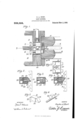
- This invention relates to sash fasteners and its object is to provide a compact and substantial device to be located in the window frame and be provided with bolts to engage racks on the sashes to prevent the movement of same in one direction as will be more fully explained in the following specification, set forth in the claim and illustrated in the drawing, where:
- Figure l is a cross sectional view through a sash frame and the sashes of a window.
- Figs. 2, 3 and Al are vertical sectional views on the lines 2 2, 3 3 and 1 -4.
- Figs. 5 and 6 are detail views.
- Fig. 7 is a view of a modilied form of fastener.
- This fastener is designed to be of few parts, substantial and strong and to be of such dimensions as to be fitted into a mortise made in an ordinary window frame with the usual compartments 11 and 12 for the sash weights and a parting strip 13.
- the upper sash 14 and the lower sash 1.5 have on their edge adjacent to the frame, the rack bai's 16 and 17 respectively with teeth having flat or horizontal sides and a reverse beveled side.
- the fastener consists of a box 18 ittin in a mortise in the wall of the frame, the depth of the box being identical with the thickness of the wall, and its outer side is a perforated plate 19 by which it may be attached to the frame.
- a box 18 ittin in a mortise in the wall of the frame, the depth of the box being identical with the thickness of the wall, and its outer side is a perforated plate 19 by which it may be attached to the frame.
- Within the box 1S are two outwardly pressed bolts 2O and 21 whose outer ends are beveled to conform with the teeth of their respective rack bars 16 and 17 while two sides of the rear end have a flange 22 projecting downward and towai'd each other.
- a filling block 27 with lateral flanges 23 for the bolts to slide on is placed in the lower front corner of the box and directly back of same is the shaft 29 of the key carrying the bit 30 that occupies the space between the anges 22 and the filling piece 27, the latter preventing the forward movement of the bit and has a broad flange 31 which prevents its dislocation and side movement into the space beneath the bolts.
- One end of the shaft 29 is squared so that an extension 34 may be fitted on the key to turn it and project beyond the side of the frame to be manipulated.
- the two cups 24 may be dispensed with and a flat spring' 33, as shown in Fig. 7, take their rear ends of the bolts.
- the two bolts are normally extended by the springs engaging the rack bars and preventing' the downward movement 0f the upper sash or the upward movement of the lower sash.
- the rear movement of the bit forces back the bolts and when the bit is in a horizontal position the upper flat face being under pressure of the flanges of the bolts, remains in that position and prevents the return of the bolts to the outer position and the sashes are free to move up or down.
- the beveled faces of the rack bars allow the sashes to be moved to their closed posi ⁇ tions.
- this sash fastener does not interfere with the operation of the sashes and particularly of the weights as has been the case with similar devices heretofore patented and in case it is desired to discontinue the use of the device the key is turned and the bit allowed to remain in its horizontal position, retracting the bolts. The extension 32 is withdrawn and the appearance of the window frame is not altered.
- the combination with a box adapted to fit in the wall of the window place and bear upon the' the bolts, cups fitting in the rear end of the the flanges, and a filling piece preventing the forward movement of the key.
Landscapes
- Engineering & Computer Science (AREA)
- Mechanical Engineering (AREA)
- Door And Window Frames Mounted To Openings (AREA)
Description
Patented Nov; 2, 1909.`
C. A. HUNT.
SASH FASTENEE.
APPLICATION FILED oGT.3o. 190s.
ATTOH/VE VS W/T/VESSES www@ W `a citizen of the United CHARLES A. HUNT, OF NEWBURGrI-I, NEW YORK.
SASH-FASTENER.
Speccation of Letters Patent.
Patented Nov. 2, 1909.
Application filed October 30, 1908. Serial No. 460,292.
To all whom it may concern.'
Be it known that I, CHARLES A. HUNT, States, residing at Newburgh, in the county of Orange and State of New York, have invented new and useful Improvements in Sash-Fasteners, of which the following is a specilication.
This invention relates to sash fasteners and its object is to provide a compact and substantial device to be located in the window frame and be provided with bolts to engage racks on the sashes to prevent the movement of same in one direction as will be more fully explained in the following specification, set forth in the claim and illustrated in the drawing, where:
Figure l is a cross sectional view through a sash frame and the sashes of a window. Figs. 2, 3 and Al are vertical sectional views on the lines 2 2, 3 3 and 1 -4. Figs. 5 and 6 are detail views. Fig. 7 is a view of a modilied form of fastener.
This fastener is designed to be of few parts, substantial and strong and to be of such dimensions as to be fitted into a mortise made in an ordinary window frame with the usual compartments 11 and 12 for the sash weights and a parting strip 13. The upper sash 14 and the lower sash 1.5 have on their edge adjacent to the frame, the rack bai's 16 and 17 respectively with teeth having flat or horizontal sides and a reverse beveled side.
The fastener consists of a box 18 ittin in a mortise in the wall of the frame, the depth of the box being identical with the thickness of the wall, and its outer side is a perforated plate 19 by which it may be attached to the frame. Within the box 1S are two outwardly pressed bolts 2O and 21 whose outer ends are beveled to conform with the teeth of their respective rack bars 16 and 17 while two sides of the rear end have a flange 22 projecting downward and towai'd each other. In the rear of the two bolts are recesses 23 in which are located cups 24 that conline coiled springs 25 to force the bolts outward into engagement with the rack bars, the forward ends of the bolts being reduced so that the shoulder 2G-permits only the beveled end to extend beyond the plate 19.
A filling block 27 with lateral flanges 23 for the bolts to slide on is placed in the lower front corner of the box and directly back of same is the shaft 29 of the key carrying the bit 30 that occupies the space between the anges 22 and the filling piece 27, the latter preventing the forward movement of the bit and has a broad flange 31 which prevents its dislocation and side movement into the space beneath the bolts. One end of the shaft 29 is squared so that an extension 34 may be fitted on the key to turn it and project beyond the side of the frame to be manipulated.
In order to further simplify the construction of the fastener the two cups 24 may be dispensed with and a flat spring' 33, as shown in Fig. 7, take their rear ends of the bolts.
The two bolts are normally extended by the springs engaging the rack bars and preventing' the downward movement 0f the upper sash or the upward movement of the lower sash. By turning the key shaft, the rear movement of the bit forces back the bolts and when the bit is in a horizontal position the upper flat face being under pressure of the flanges of the bolts, remains in that position and prevents the return of the bolts to the outer position and the sashes are free to move up or down.
The beveled faces of the rack bars allow the sashes to be moved to their closed posi` tions.
The compact construction of this sash fastener does not interfere with the operation of the sashes and particularly of the weights as has been the case with similar devices heretofore patented and in case it is desired to discontinue the use of the device the key is turned and the bit allowed to remain in its horizontal position, retracting the bolts. The extension 32 is withdrawn and the appearance of the window frame is not altered.
It is obvious that the parts may be otherwise arranged or modified without departing from the essential features shown.
What I claim as new and desire to secure by Letters Patent is:
In a sash fastener, the combination with a box adapted to fit in the wall of the window place and bear upon the' the bolts, cups fitting in the rear end of the the flanges, and a filling piece preventing the forward movement of the key.
In testimony whereof I aiiix my signature in presence of two Witnesses.
CHARLES A. HUNT.
Witnesses: i
JAMES F. DUHAMEL, MAE WV. CLINTON.
bolts and inclosing springs, abutting flanges on the rear ends of the bolts, a key held against lateral movement and operating upon
Priority Applications (1)
| Application Number | Priority Date | Filing Date | Title |
|---|---|---|---|
| US1908460292 US938584A (en) | 1908-10-30 | 1908-10-30 | Sash-fastener. |
Applications Claiming Priority (1)
| Application Number | Priority Date | Filing Date | Title |
|---|---|---|---|
| US1908460292 US938584A (en) | 1908-10-30 | 1908-10-30 | Sash-fastener. |
Publications (1)
| Publication Number | Publication Date |
|---|---|
| US938584A true US938584A (en) | 1909-11-02 |
Family
ID=3007003
Family Applications (1)
| Application Number | Title | Priority Date | Filing Date |
|---|---|---|---|
| US1908460292 Expired - Lifetime US938584A (en) | 1908-10-30 | 1908-10-30 | Sash-fastener. |
Country Status (1)
| Country | Link |
|---|---|
| US (1) | US938584A (en) |
Cited By (1)
| Publication number | Priority date | Publication date | Assignee | Title |
|---|---|---|---|---|
| US3339282A (en) * | 1966-01-24 | 1967-09-05 | Scovill Manufacturing Co | Power operated knife blades driving and retaining means |
-
1908
- 1908-10-30 US US1908460292 patent/US938584A/en not_active Expired - Lifetime
Cited By (1)
| Publication number | Priority date | Publication date | Assignee | Title |
|---|---|---|---|---|
| US3339282A (en) * | 1966-01-24 | 1967-09-05 | Scovill Manufacturing Co | Power operated knife blades driving and retaining means |
Similar Documents
| Publication | Publication Date | Title |
|---|---|---|
| US976777A (en) | Gravity sash-lock. | |
| US379910A (en) | Fastener for meeting-rails of sashes | |
| US1244725A (en) | Window-fastener. | |
| US426303A (en) | Sash-fastener | |
| US1093816A (en) | Door-lock keeper. | |
| US1118303A (en) | Lock. | |
| US875747A (en) | Sliding-door lock. | |
| US966939A (en) | Sash-lock. | |
| US796710A (en) | Window-sash fastener. | |
| US606448A (en) | Sash-fastener | |
| US926173A (en) | Sash-lock. | |
| US592974A (en) | Sash-fastener | |
| US1048401A (en) | Sash-fastener. | |
| US684080A (en) | Lock. | |
| US1046313A (en) | Lock. | |
| US476432A (en) | Sash-fastener | |
| US888911A (en) | Sash-lock. | |
| US1003896A (en) | Sliding-door latch. | |
| US335409A (en) | Sash-fastener | |
| US1100226A (en) | Sliding-door lock. | |
| US612310A (en) | Sash-fastener | |
| US514035A (en) | Sash-fastener | |
| US1074162A (en) | Window-lock. | |
| US821956A (en) | Sash-lock. | |
| US882135A (en) | Sash-fastener. |