US9375730B2 - Centrifuge with compressor motor feedback control device - Google Patents
Centrifuge with compressor motor feedback control device Download PDFInfo
- Publication number
- US9375730B2 US9375730B2 US13/446,497 US201213446497A US9375730B2 US 9375730 B2 US9375730 B2 US 9375730B2 US 201213446497 A US201213446497 A US 201213446497A US 9375730 B2 US9375730 B2 US 9375730B2
- Authority
- US
- United States
- Prior art keywords
- control
- rotation number
- temperature
- compressor
- rotor
- Prior art date
- Legal status (The legal status is an assumption and is not a legal conclusion. Google has not performed a legal analysis and makes no representation as to the accuracy of the status listed.)
- Active, expires
Links
- 238000001816 cooling Methods 0.000 claims abstract description 89
- 239000003507 refrigerant Substances 0.000 claims description 63
- 238000004364 calculation method Methods 0.000 claims description 12
- 239000002184 metal Substances 0.000 claims description 6
- 229910052751 metal Inorganic materials 0.000 claims description 6
- 230000020169 heat generation Effects 0.000 claims description 5
- 238000000034 method Methods 0.000 description 35
- 230000001133 acceleration Effects 0.000 description 28
- 230000002457 bidirectional effect Effects 0.000 description 21
- 230000008859 change Effects 0.000 description 21
- 238000009826 distribution Methods 0.000 description 20
- 238000013508 migration Methods 0.000 description 11
- 230000005012 migration Effects 0.000 description 11
- 238000012986 modification Methods 0.000 description 11
- 230000004048 modification Effects 0.000 description 11
- 238000009499 grossing Methods 0.000 description 10
- 238000005516 engineering process Methods 0.000 description 9
- 230000006641 stabilisation Effects 0.000 description 9
- 238000011105 stabilization Methods 0.000 description 9
- 238000003860 storage Methods 0.000 description 7
- 238000010586 diagram Methods 0.000 description 6
- 230000010354 integration Effects 0.000 description 6
- 238000011144 upstream manufacturing Methods 0.000 description 6
- 238000012937 correction Methods 0.000 description 5
- 230000006698 induction Effects 0.000 description 5
- 230000001360 synchronised effect Effects 0.000 description 5
- 230000007423 decrease Effects 0.000 description 4
- 230000000694 effects Effects 0.000 description 4
- 230000001172 regenerating effect Effects 0.000 description 4
- 230000004044 response Effects 0.000 description 4
- 238000010521 absorption reaction Methods 0.000 description 3
- 230000004888 barrier function Effects 0.000 description 3
- 238000006243 chemical reaction Methods 0.000 description 3
- 238000005461 lubrication Methods 0.000 description 3
- 238000012544 monitoring process Methods 0.000 description 3
- 238000009834 vaporization Methods 0.000 description 3
- 230000008016 vaporization Effects 0.000 description 3
- 102220465933 Beta-1,3-glucuronyltransferase LARGE2_R15A_mutation Human genes 0.000 description 2
- 238000013459 approach Methods 0.000 description 2
- 230000001419 dependent effect Effects 0.000 description 2
- 238000013461 design Methods 0.000 description 2
- 239000012774 insulation material Substances 0.000 description 2
- 230000010349 pulsation Effects 0.000 description 2
- 230000005855 radiation Effects 0.000 description 2
- 230000003252 repetitive effect Effects 0.000 description 2
- 239000004604 Blowing Agent Substances 0.000 description 1
- 230000002159 abnormal effect Effects 0.000 description 1
- 238000004891 communication Methods 0.000 description 1
- 238000001514 detection method Methods 0.000 description 1
- 238000001704 evaporation Methods 0.000 description 1
- 230000008020 evaporation Effects 0.000 description 1
- 238000002474 experimental method Methods 0.000 description 1
- 230000017525 heat dissipation Effects 0.000 description 1
- 238000009434 installation Methods 0.000 description 1
- 239000007788 liquid Substances 0.000 description 1
- 239000004973 liquid crystal related substance Substances 0.000 description 1
- 238000004519 manufacturing process Methods 0.000 description 1
- 239000000463 material Substances 0.000 description 1
- 230000007246 mechanism Effects 0.000 description 1
- 230000009467 reduction Effects 0.000 description 1
- 239000013643 reference control Substances 0.000 description 1
- 230000008929 regeneration Effects 0.000 description 1
- 238000011069 regeneration method Methods 0.000 description 1
- 238000011160 research Methods 0.000 description 1
- 230000000087 stabilizing effect Effects 0.000 description 1
Images


Classifications
-
- B—PERFORMING OPERATIONS; TRANSPORTING
- B04—CENTRIFUGAL APPARATUS OR MACHINES FOR CARRYING-OUT PHYSICAL OR CHEMICAL PROCESSES
- B04B—CENTRIFUGES
- B04B15/00—Other accessories for centrifuges
- B04B15/02—Other accessories for centrifuges for cooling, heating, or heat insulating
-
- B—PERFORMING OPERATIONS; TRANSPORTING
- B04—CENTRIFUGAL APPARATUS OR MACHINES FOR CARRYING-OUT PHYSICAL OR CHEMICAL PROCESSES
- B04B—CENTRIFUGES
- B04B13/00—Control arrangements specially designed for centrifuges; Programme control of centrifuges
-
- B—PERFORMING OPERATIONS; TRANSPORTING
- B04—CENTRIFUGAL APPARATUS OR MACHINES FOR CARRYING-OUT PHYSICAL OR CHEMICAL PROCESSES
- B04B—CENTRIFUGES
- B04B9/00—Drives specially designed for centrifuges; Arrangement or disposition of transmission gearing; Suspending or balancing rotary bowls
- B04B9/10—Control of the drive; Speed regulating
Definitions
- aspects of the present invention relate to a centrifuge capable of corresponding to various power supply situation without changing a configuration thereof, achieving reduction in size and low noise and realizing high-precision temperature control.
- a centrifuge in particular, a so-called high-speed refrigerated centrifuge has been widely used in the experimental laboratory or the routine operation of manufacturing process in which ability for cooling and maintaining the rotor rotating at high speed at a lower temperature (for example, 4° C.) and ability for accelerating or decelerating the rotor in a short time are required.
- This centrifuge is a device capable of obtaining samples centrifuged by holding a sample placed in tube/bottle to be separated and precipitated on a rotor, accelerating and then stabilizing the rotor set on crown in a chamber to a predetermined rotation number and then decelerating and stopping the rotor.
- the centrifuge is configured to cover voltage/frequency/power supply capacity of power sources by one design specification.
- a motor for accelerating/decelerating a rotor is subjected to a variable speed control by an inverter and both a compressor motor and a radiator fan of a cooling unit for holding a sample at a lower temperature are subjected to ON-OFF control by a single-phase induction motor.
- JP-A-H07-246351 A technology of using a variable speed compressor of an inverter control type has been proposed in JP-A-H07-246351.
- the technology disclosed in JP-A-H07-246351 has a configuration that the current supplied from the power supply or returned to the power supply forms a current waveform in which the power factor is high and the harmonic current is reduced, when a motor for rotationally driving the rotor is subjected to the power running and the power regeneration operation.
- JP-A-H06-170282 is so configured that the rotation number of a cooling fan in a region where the power frequency supplied is 60 Hz is reduced to be consistent with the rotation number thereof in a region where the power frequency is 50 Hz and the noise level of the cooling fan generated due to the change of the power frequency is not fluctuated.
- the technology disclosed in JP-A-H05-228400 relates to a centrifuge for controlling ON-OFF of a compressor motor of a cooling unit.
- a bypass pipe connecting a high-pressure side pipe and a lower-pressure side pipe and a switch are provided. As the compressor is stopped, the switch is opened to eliminate the pressure difference between the high-pressure side pipe and the lower-pressure side pipe in a short time and thus a pressure condition required for restart of the compressor can be achieved.
- an autotransformer is provided to the power input unit of the centrifuge. This is for controlling a centrifuge motor, a compressor motor and a radiator fan, which are usually difficult to match the power supply voltage.
- a tap of the autotransformer is switched so that each power voltage matches an inner operating voltage of the centrifuge.
- the current capacity of the connection power is varies. Accordingly, when the power supply capacity is small, the current of the centrifuge motor during acceleration of the rotor is adapted to the voltage specification having smallest current capacity and does not exceed the power supply capacity. In this way, the acceleration of the rotor becomes blunt.
- the operation of the compressor motor of the cooling machine is stopped until the end of the acceleration of the rotor in order to allocate the power supply voltage to acceleration of the rotor.
- the rotor is allowed to be warmed due to windage loss generated by the rotation thereof.
- this control method is adopted, original function of the centrifuge is deteriorated.
- a compressor motor and a radiator fan has been utilized, in which the rotation number of the motor is changed as the power frequency changes and thus cooling capacity is also changed.
- a compressor motor having a large capacity is employed, in order to ensure sufficient cooling capacity even at 50 Hz power supply at which the circulation amount of the refrigerant is reduced due to decrease in the rotation number thereof.
- radiator fan having a large size is employed, in order to ensure sufficient heat discharge even at 50 Hz power supply at which the heat discharge amount of the radiator is reduced due to decrease in the rotation number thereof.
- these compressor motor and condenser fan are used at 60 Hz power supply, the rotation number of the motor or the fan rises and thus operating noise becomes larger.
- a product incorporating sound insulating and noise barrier equipment has been commercialized in order to suppress the operating noise. This is the same as in a cooling fan of the motor for driving the rotor and a cooling fan for the control device.
- a related-art temperature control of the rotor ON-OFF control of the compressor motor is carried out by setting the rotation number of the compressor motor to a single rotation number depending on the power frequency. According to this control, temperature control accuracy is degraded in a region where the temperature of the rotor is greatly pulsated during rotation thereof or the windage loss of the rotor is small.
- a method for utilizing a variable speed compressor in an inverter control type has been proposed.
- the present invention has been made to solve the above-described problem and it is an object of the present invention to provide a centrifuge capable of controlling a compressor motor with high precision by carrying out a feedback of the detected temperature of the temperature sensor for measuring the temperature of the rotor and using difference between the target control temperature of the rotor and the detected temperature of the temperature sensor.
- Another object of the present invention is to provide a centrifuge capable of preventing the rotor from being subjected to a large temperature pulsation due to ON-OFF control of the compressor motor during rotation of the rotor.
- Yet another object of the present invention is to provide a centrifuge capable of achieving high-precision temperature control accuracy even in a region where the windage loss of the rotor is small.
- a centrifuge including: a rotor configured to be driven by a motor and to hold a sample; a centrifuge inverter configured to supply power to drive the motor; a chamber accommodating the rotor; a temperature sensor configured to detect the temperature of the chamber; a cooling machine configured to cool the chamber and including a compressor; a compressor inverter configured to supply power to the compressor; a compressor motor incorporated to the compressor and configured to be controlled in a variable speed by the power supplied from the compressor inverter; and a control device configured to control the centrifuge inverter and the compressor inverter based on set centrifuging operation conditions, wherein the control device carries out a feedback control of the compressor motor based on a preset temperature and a detected temperature of the temperature sensor when the rotation number of the compressor motor is larger than a predetermined rotation number, and the control device carries out an intermittent control for turning ON-OFF the cooling function of the compressor when the rotation number of the compressor motor is smaller than a predetermined rotation number
- the rotation number of the compressor motor which is compared with the predetermined rotation number, is calculated by the control device by using a difference between the preset temperature and the detected temperature of the temperature sensor.
- the calculation is a PID calculation.
- the centrifuge further includes an input unit to which the preset temperature is input, wherein the control device is configured to set a target control temperature for making the rotor to the preset temperature based on the inputted preset temperature and is configured to carry out a feedback control of the compressor motor based on the target control temperature and the detected temperature of the temperature sensor.
- control device controls the cooling function of the compressor to ON state when, during the intermittent control, the detected temperature of the temperature sensor is higher than the target control temperature and the rotation number of the compressor motor is larger than a set minimum continuous rotation number.
- control device is configured to stop the intermittent control and transit to the feedback control when the detected temperature of the temperature sensor is higher than the target control temperature for a predetermined continuous time during the intermittent control.
- the temperature sensor is installed to contact with a metal part of a lower portion of the chamber.
- the control device monitors whether a state where the rotation number of the compressor motor is lower than a predetermined rotation number has continued for the predetermined time or not and whether the rotation number of the compressor motor has reached a set minimum continuous rotation number or not, and when it is determined that the state where the rotation number of the compressor motor is lower than a predetermined rotation number has continued for the predetermined time or the rotation number of the compressor motor has reached the set minimum continuous rotation number, the control device carries out an intermittent control of the cooling function of the compressor.
- control device is configured to control the compressor motor to ON state or OFF state during the intermittent control.
- the OFF state is maintained for at least a minimum off time.
- the centrifuge further includes: an evaporator, a supply line for supplying a refrigerant compressed by the compressor to the evaporator, a return line extending from the evaporator to the compressor, a bypass line for bypassing the evaporator by shorting the return line and the supply line, and a valve provided in the bypass line, wherein the control device is configured to control the valve to ON state or OFF state during the intermittent control.
- control device is configured to control the compressor motor to rotate at the minimum continuous rotation number when the valve is controlled to OFF state.
- control device is configured to control the valve to ON state or OFF state and is configured to control the compressor motor to a continuous operation state or an intermittent operation state during the intermittent control.
- control device is configured to control the ON time of the valve to be shorter than the interval of the intermittent operation when the compressor motor is controlled to the intermittent operation state.
- a rotation number which is obtained by multiplying a coefficient obtained from a ratio of the preset rotation number of the rotor and a settable maximum rotation number of the rotor to a maximum continuous rotation number, is used as the preset rotation number of the compressor motor.
- a rotation number which is obtained by multiplying an amount of heat generation of the rotor calculated from a windage loss coefficient of the rotor registered in advance and a rotating speed of the rotor during operation as a coefficient to the maximum continuous rotation number, is used as the preset rotation number of the compressor motor.
- a centrifuge including: a rotor configured to be driven by a motor and to hold a sample; a chamber accommodating the rotor; an evaporator configured to cool the chamber; a compressor configured to compress a refrigerant which is supplied to the evaporator in a circulation manner; a capillary provided between the compressor and the evaporator; a return line connecting the evaporator and the compressor; a bypass line that connects an inlet side of the capillary and the return line; a valve that allows the refrigerant to flow the bypass line; and a throttle part provided to a part of the bypass line.
- the throttle part is formed by narrowing the diameter of the bypass line, and a sectional area of the throttle part is set larger than a minimum sectional area of the capillary and smaller than a minimum sectional area of the return line.
- a condenser configured to heat-dissipate the refrigerant compressed by the compressor is provided between the compressor and an inlet of the capillary.
- the centrifuge further includes a switching means configured to switch a flow of the refrigerant flowing from the compressor to the capillary to a flow toward the bypass line.
- the valve is a variable valve in which the flow rate can be adjusted in a variable manner and serves as the throttle part by adjusting the flow rate thereof.
- the centrifuge further includes a control device configured to control the intermittent operation or the continuous operation of the compressor, wherein the control device is configured to control ON-OFF of the valve during the intermittent operation or the continuous operation.
- the centrifuge further includes a control device configured to control open-close of the valve when the rotation number of the compressor motor becomes lower than a predetermined rotation number.
- control device is configured to control ON-OFF of the motor when the rotation number of the compressor motor becomes lower than a predetermined rotation number, and the control device is configured to switch the valve from the open state to the closed state at least during OFF state of the motor.
- the control device carries out a feedback control of the compressor motor based on a preset temperature and a detected temperature of the temperature sensor when the rotation number of the compressor motor is larger than a predetermined rotation number and the control device carries out an intermittent control for turning ON-OFF the cooling function of the compressor when the rotation number of the compressor motor is smaller than a predetermined rotation number.
- the rotation number of the compressor motor is obtained by a calculation of the control device, it is possible to obtain the rotation number of the compressor motor in a high precision in accordance with the detected temperature.
- the calculation is a PID calculation, it is possible to accurately control the temperature of the rotation chamber using a temperature feedback control including a proportional term, an integration term and a differential term.
- control device carries out a feedback control of the compressor motor based on the target control temperature and the detected temperature of the temperature sensor. Accordingly, it is possible to accurately control the temperature of the rotation chamber to a target control temperature.
- the control device controls the cooling function of the cooling machine to ON state when the detected temperature of the temperature sensor is higher than the target control temperature and the rotation number of the compressor motor is larger than a set minimum continuous rotation number, during the intermittent control.
- the intermittent control is stopped when the detected temperature is higher than the target control temperature during the intermittent control and the feedback control is carried out. Accordingly, it is possible to effectively cool the rotation chamber without causing an insufficient cooling of the rotor.
- the temperature sensor is installed to come into contact with a metal part of a lower portion of the chamber, it is possible to realize a centrifuge capable of suitably responding to the temperature change of the evaporator and having a high-precision cooling performance.
- the control device carries out an intermittent control of the cooling function of the cooling machine when it is determined that the state where the rotation number of the compressor motor is lower than a predetermined rotation number has continued for the predetermined time or the rotation number of the compressor motor reaches the set minimum continuous rotation number. Accordingly, a sufficient cooling can be achieved so that a re-rising time of temperature to the target control temperature is ensured for a predetermined time when the compressor motor is controlled to OFF state.
- the control device controls the compressor motor to ON state or OFF state during the intermittent control, it is possible to realize a centrifuge having a high-precision even in a state where the cooling of the rotation chamber may be weak.
- the OFF state is maintained over at least minimum off time when the compressor motor is controlled to OFF state.
- a bypass line for bypassing the evaporator by shorting the return line from the supply line and an electrically opened/closed valve provided in the bypass line are provided. Accordingly, it is possible to adjust the cooling capacity of the compressor while intermittently controlling the valve to ON or OFF state and without stopping the compressor.
- control device controls the compressor motor to rotate at the minimum continuous rotation number when the valve is controlled to OFF state.
- control device controls the valve to ON state or OFF state during the intermittent control and controls the compressor motor to a continuous operation state or an intermittent operation state. Accordingly, it is possible to eliminate or reduce constraints on restart inhibit time of the compressor when the compressor motor is stopped.
- control device controls the ON time of the valve to be shorter than the interval of the intermittent operation when the compressor motor is controlled to the intermittent operation state. Accordingly, it is possible to eliminate or reduce constraints on restart inhibit time of the compressor.
- the rotation number obtained by multiplying a coefficient obtained from a ratio of the preset rotation number of the rotor and a settable maximum rotation number of the rotor to a maximum continuous rotation number is used as the preset rotation number of the compressor motor, when the calculated rotation number is higher than the minimum continuous rotation number.
- the rotation number obtained by multiplying a coefficient as the amount of heat generation of the rotor calculated from a windage loss coefficient of the rotor registered in advance and a rotating speed of the rotor during operation to the maximum continuous rotation number is used as the preset rotation number of the compressor motor, when the calculated rotation number is higher than the minimum continuous rotation number.
- the bypass line connecting the inlet side of the capillary and the return line and the valve since the bypass line connecting the inlet side of the capillary and the return line and the valve are provided, it is possible to flow most of the refrigerant toward the bypass line, not toward the capillary side by controlling open-close of the valve. Further, since the throttle part is provided in the bypass line connecting the inlet side of the capillary and the return line, the refrigerant flowing through a part of the bypass line having small sectional area can be vaporized in the return line and the refrigerant can return to the compressor in a vaporized state. In this way, it is possible to prevent the service life of the compressor from being reduced.
- the throttle part is formed by narrowing the diameter (inner diameter) of the bypass line, the present invention can be realized just by properly selecting the type of pipe without preparing special member. Further, since the sectional area of the throttle part is set larger than a minimum sectional area of the capillary and smaller than a minimum sectional area of the return line, it is possible to smoothly flow a large amount of refrigerant to the bypass line.
- a condenser for dissipating heat of the refrigerant compressed by the compressor is provided between an outlet of the compressor and an inlet of the capillary, it is possible to effectively cool high-temperature refrigerant compressed by the compressor.
- a switching means is provided to switch a flow of the refrigerant flowing from the compressor to the capillary into a flow toward the bypass line, it is possible to effectively control the flow of refrigerant toward the evaporator. In this way, the temperature of the chamber can be accurately controlled.
- valve means for narrowing or opening/closing a flow passage is provided in the bypass line and is used as the throttle part, it is possible to effectively adjust the flow of refrigerant toward the evaporator by controlling open-close of the valve means.
- ON-OFF of the valve is controlled by the control device during the continuous operation of the compressor, it is possible to adjust the temperature of the chamber in accordance with ON-OFF of the valve. Further, since ON-OFF of the valve is controlled by the control device during the intermittent operation of the compressor, it is possible to balance pressures in an inlet side and an outlet side of the compressor in a short time after the compressor motor is stopped. In this way, it is possible to eliminate or reduce constraints on restart inhibit time of the compressor.
- the control device since the control device controls open-close of the valve when the rotation number of the compressor motor becomes lower than a predetermined rotation number, it is possible to control ON-OFF of the cooling function of the compressor without stopping the compressor motor. In this way, it is possible to prevent the compressor from going to a low-speed rotation state in which the compressor cannot rotate. In addition, it is possible to eliminate or reduce constraints on restart inhibit time of the compressor after the compressor motor is stopped.
- the control device controls ON-OFF of the motor when the rotation number of the compressor motor becomes lower than a predetermined rotation number and the control device switches the valve from the open state to the closed state at least during OFF state of the motor.
- the valve is in an open state when the motor is restarted and thus the refrigerant cannot flow into the bypass line. Accordingly, it is possible to cause the cooling function of the compressor to be in ON state as early as possible.
- FIG. 1 is a sectional view schematically illustrating the entire configuration of a centrifuge according to an exemplary embodiment of the present invention
- FIG. 2 is a block diagram illustrating the centrifuge according to the exemplary embodiment of the present invention.
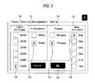
- FIG. 3 is a view illustrating a display and operation screen of a setting means for setting the distribution parameters of AC source current of the centrifuge according to the exemplary embodiment of the present invention
- FIG. 4 is a table illustrating an example of the distribution parameters of AC source current stored in the control device of the centrifuge according to the exemplary embodiment of the present invention
- FIG. 5 is a view illustrating an actual measured example of a relationship among the rotation number of the rotor, the rotation number of compressor motor and the current during an acceleration/stabilization/deceleration stop of R22A4 type rotor in the centrifuge according to the exemplary embodiment of the present invention
- FIG. 6 is a view illustrating an actual measured example of a relationship among the rotation number of the rotor, the rotation number of compressor motor and the current during an acceleration/stabilization/deceleration stop of R10A3 type rotor in the centrifuge according to the exemplary embodiment of the present invention
- FIG. 7 is a view for explaining a relationship between the type of the rotor and the power distribution in the centrifuge according to a second exemplary embodiment of the present invention.
- FIG. 8 is a block diagram illustrating the centrifuge according to a third exemplary embodiment of the present invention, in a state of being connected to a three-phase AC power supply;
- FIG. 9 is a view illustrating an actual measured example of a centrifuge according to a fourth exemplary embodiment of the present invention, in a case where R22A4 type rotor is rotated at rotation number of 22000 min ⁇ 1 and a temperature sensor 40 a is utilized in the control of cooling and maintaining the temperature of a sample at 4° C.;
- FIG. 10 is a view illustrating an actual measured example of a centrifuge according to the fourth exemplary embodiment of the present invention, in a case where R22A4 type rotor is rotated at rotation number of 22000 min ⁇ 1 and a temperature sensor 40 b is utilized in the control of cooling and maintaining the temperature of a sample at 4° C.;
- FIG. 11 is a view illustrating an actual measured example of a centrifuge according to the fourth exemplary embodiment of the present invention, in the control of rotating R22A4 type rotor at rotation number of 10000 min ⁇ 1 and cooling and maintaining the temperature of a sample at 4° C.;
- FIG. 12 is a view illustrating an actual measured example of a centrifuge according to the fourth exemplary embodiment of the present invention, in the control of rotating R10A3 type rotor at rotation number of 7800 min ⁇ 1 and cooling and maintaining the temperature of a sample at 4° C.;
- FIG. 13 is a view illustrating an actual measured example of a centrifuge according to the fourth exemplary embodiment of the present invention, in the control of rotating R22A4 type rotor at rotation number of 10000 min ⁇ 1 , cooling and maintaining the temperature of a sample at 4° C., and then changing the rotation number to 12000 min ⁇ 1 at this state;
- FIG. 14 is a view illustrating a relationship between a ratio of a preset rotation number to a maximum rotation number of a rotor 31 and an initial rotation number of a compressor motor 13 at the start of control thereof;
- FIG. 15 is a view illustrating a relationship between a target control temperature of the temperature sensor 40 a and a windage loss of a rotor at respective rotation number of the R22A4 type rotor in the centrifuge;
- FIG. 16 is a view illustrating a relationship between a target control temperature of the temperature sensor 40 a and a windage loss of a rotor at respective rotation number of the R10A3 type rotor in the centrifuge;
- FIG. 17 is a view illustrating a relationship between an initial value of I (integration term) and a temperature-time change rate (° C./sec) in which a measured temperature value of the temperature sensor 40 a is reduced during two minutes immediately before migration to PID control;
- FIG. 18 is a table illustrating an example of some combinations of the relationship between the type of a rotor 31 and the rotation number of a condenser fan 18 used in the centrifuge;
- FIG. 19 is a view illustrating an example of a relationship between the control of a compressor motor 13 and the temperature of a rotation chamber when a centrifuge according to a fifth exemplary embodiment of the present invention is in a stabilization state;
- FIG. 20 is a flow-chart illustrating a setup procedure of a target control temperature in PID control and ON-OFF control when the centrifuge according to the fifth exemplary embodiment of the present invention is in a stabilization state;
- FIG. 21 is a view illustrating an example of a control procedure of the compressor motor 13 according to a modification of the fifth exemplary embodiment of the present invention.
- FIG. 22 is a view illustrating an example of a migrating procedure from feedback control to ON-OFF control in the compressor motor 13 according to a sixth exemplary embodiment of the present invention.
- FIG. 23 is a view illustrating an example of a migrating procedure from feedback control to ON-OFF control in the compressor motor 13 according to a modification of the sixth exemplary embodiment of the present invention.
- FIG. 24 is a view illustrating an example of a migrating procedure from feedback control to ON-OFF control in the compressor motor 13 according to a second modification of the sixth exemplary embodiment of the present invention.
- FIG. 25 is a view illustrating an example of a migrating procedure from feedback control to ON-OFF control in the compressor motor 13 according to a third modification of the sixth exemplary embodiment of the present invention.
- FIG. 26 is a block diagram of a centrifuge 301 according to a seventh exemplary embodiment of the present invention.
- FIG. 27 is a view illustrating an example of a temperature control procedure using a valve 360 of the centrifuge 301 according to the seventh exemplary embodiment of the present invention.
- FIG. 28 is a view illustrating an example of a temperature control procedure using a valve 360 of the centrifuge 301 according to a modification of the seventh exemplary embodiment of the present invention.
- FIG. 1 is a sectional view schematically illustrating the entire configuration of a centrifuge 1 according to an exemplary embodiment of the present invention.
- the centrifuge 1 includes a rotation chamber 48 inside a body thereof.
- a centrifuge motor 9 as a driving source is provided below the rotation chamber.
- As the centrifuge motor 9 a high-frequency induction motor in which a variable speed control by an inverter is allowed or a magnet brushless synchronous motor is utilized.
- a rotation sensor 24 for detecting a rotation number of an output shaft (motor shaft) is provided on a lower portion of the centrifuge motor 9 and a DC fan 25 for cooling the centrifuge motor 9 is provided on a side portion thereof.
- a rotor 31 is detachably mounted on a leading end of the output shaft (motor shaft) which extends upward from the centrifuge motor 9 to an interior of a chamber 32 .
- the chamber 32 is an approximately cylindrical vessel and provided at its upper portion with a circular opening.
- the circular opening on an upper side of the chamber 32 A is covered with a door 43 in which an insulation material is embedded.
- the door is configured to open and close the rotation chamber of the rotor 31 .
- the door 43 is locked in a closed state by a lock mechanism (not-illustrated) during the operation of the centrifuge 1 .
- a pipe evaporator 33 is wound around an outer periphery of the chamber 32 .
- the surrounding of the chamber is thermally insulated by an appropriate insulation material 34 such as a blowing agent.
- a compressor 35 is provided for compressing a refrigerant to supply the refrigerant in a circulation manner and includes a compressor motor 13 .
- the compressor supplies the compressed refrigerant from a discharge pipe 36 to a condenser 37 .
- the refrigerant is radiated and cooled by wind from a condenser fan 18 of the condenser 37 so that the refrigerant is liquefied. Further, the refrigerant is sent to a lower portion of the evaporator 33 wound around the outer periphery of the chamber 32 through a capillary 38 .
- the heat is generated in the rotation chamber 48 due to a windage loss during the rotation of the rotor 31 and absorbed in vaporization heat generated during the evaporation of the refrigerant in the evaporator 33 .
- Vaporized refrigerant is discharged from the top of the evaporator 33 and returns to the compressor 35 through a suction pipe 42 .
- a temperature sensor 40 a is provided at a portion contacting a metal part in a bottom of the chamber 32 in which the rotor 31 is accommodated and indirectly detects the temperature of the rotor 31 .
- a seal rubber 41 is made of a rubber and configured to plug a through-hole through which an output shaft of the centrifuge motor 9 penetrates.
- a temperature sensor 40 b (illustrated in the dashed-line) is embedded in the seal rubber and used to indirectly detect the temperature of the rotor 31 .
- two temperature sensors 40 a and 40 b are provided in the present exemplary embodiment, it is not essential to employ two temperature sensors. For example, only one of them may be used. Further, the temperature sensors may be provided in other locations. However, in this case, care must be taken because the detection accuracy can be changed when indirectly detecting the temperature of the rotor 31 .
- a control box 29 for accommodating a control device (will be described later) is provided inside of the centrifuge 1 .
- the control device includes a micro computer, a timer and a storage device, etc., all of which are not illustrated.
- the control device is configured to control the whole of the centrifuge 1 including the rotation control of the centrifuge motor 9 and the operation control of a chiller for controlling the temperature of the rotation chamber 48 . Accordingly, various electric equipments or electronic circuits are included inside of the control box 29 and respectively heat up when being operated. For this reason, a DC fan 26 for cooling is provided and sends cooling air to the electric equipments or electronic circuits when the control device is activated.
- the detected temperature of the temperature sensor 40 a is fed back to the control device 20 .
- the rotation number of a compressor motor 13 provided in the compressor 35 is so controlled that the sample in the rotor 31 reaches a predetermined target temperature.
- five electric drive motors of the DC fan 25 , the DC fan 26 , the centrifuge motor 9 , the compressor motor 13 and the condenser fan 18 are included in the centrifuge 1 .
- three electric drive motors of the centrifuge motor 9 , the compressor motor 13 and the condenser fan 18 are particularly involved in the present invention.
- An operating panel 21 as an example of an input unit is provided on the top of the centrifuge 1 .
- the operating panel 21 is a touch-type liquid crystal display panel.
- Centrifuge operation conditions such as the operating rotation number (rotation speed) setting, the operation time setting and the cooling temperature setting of the rotor 31 holding the sample are inputted through the operating panel 21 and various information are displayed on the operating panel 21 .
- FIG. 2 is a block diagram illustrating the centrifuge according to the exemplary embodiment of the present invention. As illustrated in the dashed line, the centrifuge is accommodated in the control box 29 .
- a power supply line 2 is connected to a single-phase AC power supply 22 .
- a bidirectional converter 4 a unidirectional converter 5 , a rectifier 15 and a DC power supply 6 are connected to the power supply line 2 .
- a centrifuge motor current sensor 19 can measure the current waveform in a state of being insulated.
- the bidirectional converter 4 is operated as a boost converter through the centrifuge motor current sensor 19 to convert the power of the AC power supply 22 into a DC power, during the power rectification.
- the bidirectional converter is operated as a step-down converter to convert the DC power into AC power and regenerates the power of the AC power supply 22 , during the power inversion.
- the bidirectional converter has a high power factor.
- DC power supply end of the bidirectional converter 4 is connected to a centrifuge inverter 8 via a smoothing condenser 7 .
- Inversion terminal of the centrifuge inverter 8 is connected to the centrifuge motor 9 which is constituted by the high-frequency induction motor or the magnet brushless synchronous motor and configured to rotationally drive the rotor 31 .
- the configuration and operation of the bidirectional converter 4 has been described in detail in JP-A-H07-246351.
- AC side of the bidirectional converter is connected to the AC power supply 22 and DC side thereof is connected to the smoothing condenser 7 .
- a switching device such as a bipolar transistor, IGBT, FET, etc., are connected in opposite direction parallel to a plurality of rectifying devices constituting the bidirectional converter 4 .
- the bidirectional converter 4 is not limited to such a configuration.
- a related-art bidirectional converter may be used as the bidirectional converter.
- the current waveform of the passing current has the same shape as and is phase-synchronous with the sinusoidal waveform of the supply voltage waveform while boosting the DC power to a constant DC voltage higher than a peak value of the supply voltage by the boost function of the bidirectional converter 4 . Therefore, a receiving power factor is improved.
- the voltage of the DC power supply end is lowered by the step-down function of the bidirectional converter 4 while being substantially same as the supply voltage of AC power supply 22 and following the voltage waveform thereof.
- the output of the voltage sensor 44 is transmitted to the control device 20 via an input control line 23 and is monitored by the control device while being utilized in the control operations.
- the power supply line 2 is also connected to the DC power supply 6 .
- DC fan 25 and DC fan 26 are respectively connected to DC constant voltage output end of the DC power supply 6 via controls switches 10 , 14 for controlling ON-OFF of the DC fan 25 and the DC fan 26 .
- the DC constant voltage output end of the DC power supply 6 is connected to the control device 20 .
- a switching type stabilized power supply can be used as the DC power supply 6 and is capable of handling a wide range of supply voltage of the AC power supply 22 . In this way, according to the present exemplary embodiment, it is possible to obtain a constant rotation number regardless of the power voltage/frequency by using each fan as DC fan, instead of AC fan. Further, it is also possible to securely obtain a constant cooling capacity.
- the unidirectional converter 5 is connected to the AC power supply 22 via a compressor motor current sensor 28 .
- the current sensor can measure the current waveform while insulating the current waveform.
- the current sensor converts the power of the AC power supply 22 into DC power in a high power factor.
- the DC power supply end of the unidirectional converter 5 is connected to a compressor inverter 12 while the smoothing condenser 11 is provided therebetween.
- the inversion terminal of the compressor inverter 12 is connected to the compressor motor 13 such as the high-frequency induction motor or the magnet brushless synchronous motor.
- the current waveform of the passing current has the same shape as and is phase-synchronous with the sine waveform of the supply voltage waveform while supplying DC power from the DC power supply end of the unidirectional converter 5 to the smoothing condenser 11 and boosting the DC power to DC power several tens of volts higher than the peak value of the AC power supply 22 by the boost function of the unidirectional converter. Therefore, a receiving power factor is improved.
- the charging voltage of the smoothing condenser 11 is supplied to the compressor inverter 12 and converted into AC voltage value by the compressor inverter 12 to drive the compressor motor 13 .
- the rotation number of the compressor motor 13 is dependent on the frequency of the AC voltage and the maximum allowable rotation number thereof is slightly smaller than 120 Hz, that is, 7200 min ⁇ 1 .
- the compressor motor 13 is always subjected to a reaction force for compressing the refrigerant. As soon as the power supply is shut-off, the compressor motor is decelerated and stopped and thus it is not possible to generate a regenerative power. Accordingly, there is no necessary a bidirectional conversion function by the bidirectional converter as in the case of the circuit of the centrifuge motor 9 .
- a voltage sensor 45 is provided between the unidirectional converter 5 and the compressor inverter 12 and measures the charging voltage of the smoothing condenser 11 in a state of being insulated. The output of the voltage sensor 45 is transmitted to the control device 20 via an output control line 27 and is monitored by the control device while being utilized in the control operations.
- the power of the AC power supply 22 is also supplied to a rectifier 15 via a power supply line 3 .
- a DC output end of the rectifier 15 is connected to a condenser fan inverter 17 via the smoothing condenser 16 .
- a condenser fan 18 including the high-frequency induction motor or the magnet brushless synchronous motor is connected to an output end of the condenser fan inverter 17 .
- Power requirements of the centrifuge motor 9 and the compressor motor 13 are usually up to about 2 to 4 kW and the power requirements of the DC power supply 6 and the condenser fan 18 are about 100 W in total. It is not necessary to improve the power factor by a boost operation. Further, when it is necessary to suppress the power line harmonics, a reactor may be provided in a power input. When it is necessary to further suppress the power line harmonics, it may be preferable to improve the power factor.
- a selecting signal for causing the bidirectional converter 4 to operate in any one of a boost converter operation or a step-down converter operation and a selecting signal for causing the DC fans 25 , 26 to operate in any one of a rotation mode or a stop mode by ON-OFF control of the control switches 10 , 14 are outputted.
- Signal for performing voltage feedback control using pulse width modulation (PWM), for example, is outputted to each of the centrifuge inverter 8 , the compressor inverter 12 and the condenser fan inverter 17 and further to each of the centrifuge motor 9 , the compressor motor 13 and the condenser fan 18 in order to absorb the changes in the supply voltage and apply an appropriate voltage depending on the rotation status of these motors.
- PWM pulse width modulation
- a signal for variable speed control of a rotation number of the centrifuge motor 9 including ON and OFF by the control of the output voltage/output frequency is outputted to the centrifuge inverter 8 .
- a variable speed control of a rotation number thereof including ON and OFF are performed for each of the compressor inverter 12 and the condenser fan inverter 17 .
- a method for controlling these motors is carried out by the control device 20 and is similar to a known VVVF control technology, or a sensor using vector control technology or sensorless vector control technology. These motors are driven by providing a suitable voltage and a slipping or a synchronous frequency depending on the rotation number of the motors.
- the rectifier 15 of the condenser fan inverter 17 can respond to various voltages of the AC power supply 22 without using an expensive boost function, it is possible to achieve an inexpensive configuration of performing the voltage feedback control using pulse width modulation in order to use the operation voltage of the condenser fan 18 as a minimum voltage of the AC power supply 22 and respond to other high voltages of the AC power supply 22 .
- a current sensor 47 and a voltage sensor 46 are provided on the condenser fan inverter 17 and can measure the current waveform in a state of being insulated. A signal thereof is inputted to the control device 20 via the input control line 23 . The current of the condenser fan inverter 17 and the voltage of the smoothing condenser 16 can be monitored from the control device 20 .
- a voltage monitoring signal of a voltage sensor 30 detecting the line voltage of the AC power supply 22 , absorbing the changes in the voltage of the AC power supply 22 and causing the control device 20 to perform the voltage feedback control for each of the centrifuge inverter 8 , the compressor inverter 12 and the condenser fan 18 , a current monitoring signal of the centrifuge motor current sensor 19 provided in an input unit of the bidirectional converter 4 and detecting the current flowing in the bidirectional converter 4 , a current monitoring signal of the compressor motor current sensor 28 provided in an input unit of the unidirectional converter 5 and detecting the current flowing in the unidirectional converter 5 and a signal of the rotation sensor 24 detecting the rotation number of the centrifuge motor 9 .
- the control device 20 is provided with the operating panel 21 for inputting centrifuge operation conditions such as the type, the operating rotation number setting, the operation time setting and the cooling temperature setting of the rotor 31 centrifuging the sample and storing the setting values.
- the control device is configured to output the distribution parameters of the source current of the AC power supply 22 connected thereto to the operating panel 21 , depending on the setting values. Further, the control device 20 can store a supply voltage setting value and the allowable rated current as the parameters.
- the display contents of the operating panel 21 will be described by referring to FIG. 3 .
- 200V series are used as an input voltage and the rated supply voltage of the AC power supply 22 varies depending on the country of the destination.
- 200V, 208V, 220V, 230V, or 240V is used as the rated supply voltage.
- 400V is used as the rated supply voltage.
- a voltage between a power ground PE and each line is used as the rated supply voltage.
- 230V is used as a voltage between each phase.
- range of voltage fluctuation has a lower limit of ⁇ 15% therefrom and an upper limit of +10% therefrom.
- rated power supply capacity of the AC power supply 22 on one side is 30 A, 24 A, 23 A, 22 A or 21 A in single-phase alternating current and 30 A or 15 A in three-phase alternating current.
- the power frequency is selected from 50Hz or 60Hz and the characteristics of the AC power supply are not affected due to the difference of the power frequency.
- any one of the power frequency is selectively utilized in other control and thus the power frequency is selected for the present.
- Such a power parameter is inputted via an operating screen of the operating panel 21 and stored in the control device.
- FIG. 3 illustrate a display example of the operating panel 21 in a state where a rated voltage of 200V, a power frequency of 50 Hz, a rated current of 30 A and a single-phase alternating current condition are set as the power parameters.
- the rated voltage is listed in Input Voltage section 130
- the frequency is listed in Frequency section 131
- the number of phase is listed in Phase section 132
- the rated current is listed in Current section 133 .
- the rated voltage is selected depending on the power supply of the destinations.
- Such a setting operation is carried out by the manufacturer during the factory shipment of the centrifuge, for example. However, such a setting operation may be carried out again in a case where the destination is changed in a relay hub after the product shipment or in a case where a local worker uses a power supply different from the setting power supply during the factory shipment.
- the control device 20 determines the distribution ratio of the power to the centrifuge motor 9 and the compressor motor 13 based on the setting rated current.
- a total input power is 6000 W as a result of 200V times 30 A and a fixed power consumption of the compressor motor 13 is 2400 W.
- the acceleration of the rotor 31 is controlled by a power of 3600 W remained after subtracting the fixed power consumption of 2400 W from the total input power of 6000 W. Accordingly, the power consumption of the centrifuge motor 9 becomes 3600 W.
- the control device 20 controls the centrifuge inverter 8 and the compressor inverter 12 via the output control line 27 so that the passing current of the centrifuge motor current sensor 19 becomes 18 A and the rotation number of the compressor motor 13 becomes 58 Hz (which corresponds to 3480 min ⁇ 1 as a result of 58 Hz times 60) during the acceleration of the centrifuge motor 9 .
- the power of 2400 W distributed to the compressor motor 13 is a maximum power consumption of the compressor motor 13 when being operated at 58 Hz.
- the rotation number of 58Hz is the rotation number of the compressor motor 13 capable of preventing the rotor 31 being excessively overheated during the acceleration period thereof.
- the power consumption of the compressor motor 13 increases as the heat absorption of the evaporator 33 increases.
- FIG. 4 illustrates an example of the distribution parameters of the AC source current of the centrifuge 1 according to the present exemplary embodiment.
- These distribution parameters are stored in a storage means of the control device 20 in the form of a table, for example, in advance.
- a combination of each rated supply voltage/rated power supply capacity and the allowable input power and a distribution parameter corresponding to the combination are included in the table.
- These indicate the factors of the distribution parameter and determined examples as a result of operating the screen of FIG. 3 .
- the setting conditions in FIG. 3 indicate an example of using the rated current of 30 A at the single-phase rated voltage of 200V.
- each parameter in a condition for operating the centrifuge under the same noise and cooling condition is stored.
- the allowable input power becomes 5040 W when the rated voltage of the AC power supply 22 is 240V and the rated current thereof is 21 A.
- the input power of the centrifuge motor 9 is set as 2640 W and the control device 20 outputs a slipping instructions to the centrifuge inverter 8 so that the output of the centrifuge motor current sensor 19 becomes 11.00 A.
- the term numbers of 1 to 6 in FIG. 4 respectively use the rotor 31 of different family and it is difficult to cool the rotor. Accordingly, the rotation number of the condenser fan 18 is set as 54 Hz.
- the allowable input power of the centrifuge motor 9 is calculated as 6900 W.
- the input power of the centrifuge motor 9 is determined as 3450 W because the source rated current of the centrifuge motor current sensor 19 is restricted to 15 A.
- the rated current is set as 30 A/phase (per each one phase) as illustrated in the term number 6
- the allowable input power of the centrifuge motor 9 is calculated as 13800 W.
- the input power of the centrifuge motor 9 is determined as a maximum of 3900 W due to the restriction of the driving torque during acceleration thereof and the source rated current of the centrifuge motor current sensor 19 is restricted to 16.95 A.
- the rotation numbers of the centrifuge motor 9 and the compressor motor 13 are preset in accordance with the combination of each rated supply voltage/rated power supply capacity and the allowable input power. Further, the rotation numbers are individually set in during the acceleration of the rotor 31 and after the stabilization thereof.
- the noise and cooling condition of the centrifuge according to the present invention is limited to the conditions mentioned above. Accordingly, the distribution parameters can be also variously set, regardless of the parameters mentioned above.
- the centrifuge can be driven in the maximum capacity thereof under various power situations of the AC power supply 22 depending on the setting values.
- the identification of the rotor 31 is particularly advantageous for realizing the present exemplary embodiment.
- Such an identification of the rotor 31 may be automatically acquired by a rotor identification device disclosed in JP-A-H11-156245 or an operator may manually set the rotor 31 from the operating panel 21 to identify the rotor.
- FIG. 5 is a view illustrating an actual measured example of an operation in which the control device 20 causes a R22A4 type rotor (which has low moment of inertia and is used in the high-speed refrigerated centrifuge commercially available from the present applicant) to be accelerated at relatively high-speed rotation of a maximum rotation number of 22000 min ⁇ 1 and a moment of inertia of 0.0141 kg ⁇ m 2 , to be stabilized at 22000 min ⁇ 1 and then to be decelerated, depending on the distribution parameters determined as mentioned above.
- a R22A4 type rotor which has low moment of inertia and is used in the high-speed refrigerated centrifuge commercially available from the present applicant
- the rotation numbers of the rotor 31 and the centrifuge motor 9 are represented by reference numeral 100 (left vertical axis: rotation number (min ⁇ 1 ) scale), the rotation number of the compressor motor 13 is represented by reference numeral 101 (right vertical axis: rotation number (Hz) scale), the output of the centrifuge motor current sensor 19 is represented by reference numeral 102 (right vertical axis: current (A) scale), the output of the compressor motor current sensor 28 is represented by reference numeral 103 (right vertical axis: current (A) scale).
- Reference numeral 104 represents a total current value (right vertical axis: current (A) scale) of the output of the centrifuge motor current sensor 19 and the output of the compressor motor current sensor 28 .
- the power consumptions of the condenser fan 18 , the DC fan 25 and the DC fan 26 is approximately 100 W in total and therefore the total current value 104 is substantially equal to the current consumption of the entire centrifuge.
- the rotation number of the compressor motor 13 is controlled to the rotation number of 58 Hz in which the thermal equilibrium state of the cooled rotor 31 is achieved, as represented by line 101 of the rotation number.
- the rotation number of 58 Hz there is no case that the rotor 31 is carelessly warmed during acceleration thereof and also the current consumption of the entire centrifuge which temporarily increases for the acceleration of the rotor 31 can be constantly maintained at a level slightly lower than approximately 30 A, as represented by line 104 of the total current value.
- the control device 20 outputs a slipping instruction to the centrifuge inverter 8 using the output of the centrifuge motor current sensor 19 as a feedback signal so that the passing current of the centrifuge motor current sensor 19 becomes about 18 A and the input power of the centrifuge motor 9 becomes about 3600 W, as represented by line 102 .
- the control device 20 is operated within the setting rated power capacity of about 6000 W at the current of about 30 A when the input power from the AC power supply 22 is 200V, in conjunction with the maximum input power of the compressor motor 13 of about 12 A and the power consumption of about 2400 W, as represented by line 103 . Accordingly, the centrifuge has exhibited its maximum ability.
- a constant current control method for finely controlling the rotation number of the compressor motor 13 may be carried out so that the passing current of the unidirectional converter 5 becomes a constant current.
- this method it is difficult to stabilize the passing current due to a bad response of the rotation number. Rather, it is desirable to maintain the rotation number of the compressor motor 13 in a predetermined rotation number, since a constant current characteristic is excellent and an abnormal noise is also not generated.
- the rotation number of the compressor motor 13 is increased to 65 Hz, for example, to strongly cool the rotor 31 .
- the rotation number of 65 Hz is the rotation number of the compressor motor 13 capable of suppressing a noise generated from the compressor 35 below a prescribed noise limit values of the centrifuge, for example, below 58 dB. Consequently, it is possible to suitably suppress a noise from the centrifuge 1 .
- the centrifuge 1 can be made in a compact manner and thus space-saving can be realized. Further, since the operation and cooling of the rotor can be completely independently controlled in an optimal manner and the receiving power factor is high, it is possible to accelerate or decelerate the rotor in a short time while strongly cooling the rotor 31 rotating at high speed. In this way, the power line harmonics can be reduced.
- the current is temporarily increased immediately before the stop of the rotor 31 , as represented by line 102 . This is intended to perform DC braking operation for preventing the centrifuged sample from being scattered using a smoothing deceleration.
- FIG. 6 illustrates the same characteristics as in FIG. 5 , in a case where a R10A3 type rotor (which has high moment of inertia and is used in the high-speed refrigerated centrifuge commercially available from the present applicant) is accelerated for about 100 seconds at relatively low-speed rotation of a maximum rotation number of 10000 min ⁇ 1 and a moment of inertia of 0.277 kg ⁇ m 2 , stabilized at 10000 min ⁇ 1 and then decelerated and stopped in about 90 seconds after the stabilization, using the same control method as in FIG.
- a R10A3 type rotor which has high moment of inertia and is used in the high-speed refrigerated centrifuge commercially available from the present applicant
- Line 110 (left vertical axis: rotation number (min ⁇ 1 ) scale) represents the rotation number of the centrifuge motor 9
- line 111 (right vertical axis: rotation number (Hz) scale) represents the rotation number of the compressor motor 13
- line 112 (right vertical axis: current (A) scale) represents the output of the centrifuge motor current sensor 19
- line 113 (right vertical axis: current (A) scale) represents the output of the compressor motor current sensor 28
- Line 114 (right vertical axis: current (A) scale) represents a total current value of the output of the centrifuge motor current sensor 19 and the output of the compressor motor current sensor 28 .
- control device 20 is operated within the setting rated power capacity of about 6000 W at the current of about 30 A when the input power from the AC power supply 22 is 200V and the centrifuge of the present exemplary embodiment has exhibited its maximum ability, regardless of moment of inertia value of the rotor 31 .
- selection and setting in the control of the rotation number of the condenser fan 18 will be described.
- the control selection range of the rotation number of the condenser fan 18 is ranged from 0 Hz to 60 Hz and the maximum power consumption thereof is 75 W, the power consumption of entire centrifuge is hardly affected by the power consumption of the condenser fan.
- the increase in the rotation number significantly affects on the noise, it is necessary to suppress the rotation number of the condenser fan as long as the cooling capacity of the rotor 31 can be secured.
- FIG. 15 is a graph illustrating the magnitude of a target control temperature and a windage loss of R22A4 type rotor.
- FIG. 16 is a graph illustrating the magnitude of a target control temperature and a windage loss of R10A3 type rotor.
- lines 170 to 172 represent target control temperatures of the R22A4 type rotor when being cooled to respective preset temperature and line 173 represents the relationship between the magnitudes of the rotation number and the windage loss of the rotor 31 .
- the difference of the target control temperature in accordance with the difference of the rotor 31 will be explained when the target control temperature is at 4° C.
- the R22A4 type small-capacity high-speed rotation rotor has a small surface area and heat sources of windage loss thereof are concentrated. Accordingly, a large cooling capacity is required even though the windage loss is small.
- the R10A3 type large-capacity low-speed rotation rotor has a large surface area and heat sources of windage loss thereof are widely spread. Accordingly, only a small cooling capacity is sufficient even though the windage loss is large.
- a cover member for covering the outer surface of the rotor is required in order to reduce the windage loss and a great wind noise tends to occur due to the deformation of the cover member during rotation of the rotor.
- the upper limit of the rotation number of the condenser fan 18 is automatically selected and set in accordance with the type of the rotor 31 used in the centrifuge, as illustrated in FIG. 18 . Meanwhile, the R15A type rotor in FIG.
- 18 is a rotor (which is used in the high-speed refrigerated centrifuge commercially available from the present applicant and has medium moment of inertia) that rotates at relatively low-speed rotation of a maximum rotation number of 15000 min ⁇ 1 and a moment of inertia of 0.1247 kg ⁇ m 2 .
- the preset rotation number of the condenser fan 18 significantly affecting on the cooling capacity and the noise may be added to the factors for determining the distribution parameters mentioned above.
- the rotation number of the condenser fan 18 may be suitably changed by considering the relationship between the required cooling capacity and the rotation number of the compressor motor 13 or the rotation number of the centrifuge motor 9 .
- the configuration of the centrifuge 1 according to the present exemplary embodiment does not depend on the supply voltage, there is no need an autotransformer. Further, there is no need to switch a tap matching to the voltage of the destination. In this way, a compact product can be made and thus productivity is improved. Further, since the configuration of the centrifuge does not depend on the supply frequency and the compressor motor and the condenser fan as major noise sources are operated at a suitable rotation number using variable speed control, the centrifuge having excellent sound insulating properties and noise barrier performance can be realized.
- the maximum performance can be always realized in accordance with the power conditions.
- FIG. 7 a control for changing the distribution ratio of the power to the centrifuge motor 9 and the compressor motor 13 in accordance with the type of the rotor 31 mounted will be described by referring to FIG. 7 .
- the type of the rotor 31 and the distribution parameters are stored in a storage device in advance in the form of a table.
- the control device 20 identifies the type of the rotor 31 mounted and controls the power supply to the centrifuge inverter 8 and the compressor inverter 12 in accordance with the distribution parameters read out from the storage device.
- control device 20 is operated within the setting rated power capacity of about 6000 W at the current of about 30 A when the input power from the AC power supply 22 is 200V.
- R22A4 type small-capacity high-speed rotation rotor of term number 1 since the acceleration time is short but large cooling capacity is required, the power of the centrifuge motor 9 during acceleration is restricted to approximately 3350 W. Meanwhile, the rotation number of the compressor motor 13 is made to a high-speed of 64 Hz to secure sufficient cooling capacity.
- R10A3 type large-capacity low-speed rotation rotor of term number 3 since the acceleration time is long but large cooling capacity is not required, the power supply distributed to the centrifuge motor 9 is increased to approximately 3900 W to shorten the acceleration time, during the acceleration thereof. Meanwhile, the rotation number of the compressor motor 13 is made to a low-speed of 50 Hz to reduce the cooling capacity. Since the rotor of term number 2 is R15A type medium-capacity medium-speed rotation rotor, the rotation number of the compressor motor 13 and the power of the centrifuge motor 9 during acceleration are determined in the middle of term number 1 and 3. Meanwhile, in a case of other power condition where the rated voltage and rated current of the AC power supply 52 are changed, it is preferable that the distribution parameters are determined in advance based on the above ideas and stored in the storage device.
- the distribution parameters are set and stored so that the rotation number of the compressor motor 13 and the power of the centrifuge motor 9 during acceleration can be suitably distributed to match the acceleration time and cooling property of the rotor 31 in accordance with the power supply capacity of the destinations and the type of the rotor 31 mounted. Further, since the centrifuge is controlled to determine the distribution ratio of the power to the centrifuge motor 9 and other motors based on the above contents, the optimal performance can be always realized in accordance with the power conditions.
- FIG. 8 a third exemplary embodiment of the present invention will be described by referring to FIG. 8 .
- the third exemplary embodiment is different from the first exemplary embodiment of FIG. 1 in that a three-phase AC power supply is used as a power supply and the power supply line 2 and the power supply line 3 are connected to a different phase of the AC power supply 52 .
- Other parts with same reference numerals are the same as in the block diagram of the first exemplary embodiment illustrated in FIG. 1 .
- the centrifuge controls the rotor 31 to be stabilized in a predetermined rotation number
- the power consumption becomes larger in a case of cooling and keeping the rotor at a temperature of 4° C., for example.
- a normal power consumed at the centrifuge motor 9 is substantially same as the power consumed at the compressor motor 13 and becomes approximately 1 kW to 2 kW.
- a value obtained by multiplying a conversion efficiency of the powers into the driving force to these powers is equal to the windage loss of the rotor 31 .
- both the power consumption of the DC power supply 6 and the power consumption of the condenser fan 18 are approximately 50 W to 100 W, the power consumptions of the supply line 2 and the supply line 3 are substantially same.
- the power consumptions are balanced without being biased.
- the method for connecting the supply line 2 and the supply line 3 to the AC power supply 22 as illustrated in FIG. 1 is a versatile connection method since it is very easy to separate the connection therebetween and reconnect as illustrated in FIG. 8 or vice versa.
- the bidirectional converter 4 as a converter of the large-capacity centrifuge motor 9 enhances the power factor of the AC power supply 22 and is boost controlled to be a DC voltage obtained by adding about 10V to the peak voltage of 264V power supply voltage. Since the DC output voltage charged into the smoothing condenser 7 is controlled to a constant voltage of about 385V, the inverter circuit of the centrifuge motor 9 can be stably controlled in response to the fluctuation of the supply voltage of the AC power supply 22 . Similarly, the compressor motor 13 has a large capacity. The unidirectional converter 5 supplies power to the compressor motor 13 and can respond to 170V to 264V supply voltage fluctuation or the supply frequency change of between 50 Hz and 60 Hz. Accordingly, the compressor motor 13 is also controlled in a stable manner.
- the ability to cool a chamber 32 depends on the rotation number of the compressor motor 13 of the compressor 35 .
- the ability is greatly influenced by the air volume of the condenser fan 18 cooling the condenser 37 .
- the noise and maximum cooling capacity of the centrifuge are changed in accordance with the supply frequency environment of 50 Hz and 60 Hz to be used.
- the air volume per hour is 1800 m3 and the noise level is approximately 50.6 dB in the power frequency of 50 Hz
- the air volume per hour is 2040 m3 and the noise level is approximately 54.3 dB in the power frequency of 60 Hz. That is, the air volume increases by approximately dozen % but the noise level also rises by approximately 3 to 4 dB in the power frequency of 60 Hz.
- the air volume and the noise level in the power frequency of 60 Hz are larger than in the power frequency of 50 Hz.
- the ability to cool the chamber 32 becomes larger in the condenser fan 18 having the power frequency of 60 Hz, as compared to the power frequency of 50 Hz.
- the maximum cooling ability of the rotation chamber 48 of the centrifuge is small and the noise level thereof is also small.
- the maximum cooling ability of the rotation chamber 48 of the centrifuge is large but the noise level thereof is also large.
- the DC voltage of the DC power supply 6 is, for example, 24V and DC 24V is supplied even though the supply voltage varies in a range of 170 V to 264V. Accordingly, the DC fan 25 and the DC fan 26 are maintained in a constant rotation number and the air volume and the wind pressure does not change. In this way, it is possible to cool the centrifuge motor 9 or the control box 29 without depending on the supply voltage and the power frequency and without change in the noise level.
- the centrifuge is operated in such a way that the supply voltage and the power frequency are freely selected and the distribution parameters are determined by stored setting results of the connected supply voltage and the allowable rate current. Accordingly, it is not necessary to prepare the autotransformer even though the voltage of AC power supply connected is variously changed and it is possible to eliminate the difference in the cooling ability and the noise level due to the difference of the power frequency of 50 Hz and 60 Hz. As a result, the centrifuge having optimal maximum cooling ability and noise barrier performance can be realized. Further, not only connection to the single-phase AC power supply and but also connection to the multi-phase power supply can be easily changed.
- the multi-phase power supply causes the bidirectional converter 4 of the centrifuge motor 9 and the unidirectional converter 5 of the compressor 13 to be powered by different phases. Accordingly, the current amount used per respective phase can be reduced. As result, the operation of the centrifuge becomes possible, even though the source impedance of the AC power supply is high.
- a temperature correction value is calculated in advance by an experiment, etc., and corresponds to the difference between the target temperature (target control temperature) of the temperature sensor 40 b during the rotation of the rotor 31 and the temperature of the sample in the rotor 31 . In order to compensate for errors occurring in such a temperature control, the temperature correction value is utilized to realize high precision.
- a radiation thermometer is provided in the rotation chamber 48 of the rotor 31 .
- the radiation thermometer is configured to directly measure the temperature of the bottom surface of the rotor 31 . The temperature thus measured is used as the target control temperature to control and maintain the rotor 31 at a desired temperature.
- a method indirectly measuring the temperature of the chamber 32 by the temperature sensors 40 a , 40 b such as a thermistor will be described below.
- the temperature correction value In the temperature correction value, the occurring amount due to the windage loss and the amount of heat exchange between the chamber 32 and the rotor 31 are changed depending on the type/shape of the rotor, in addition to the operating rotation number of the rotor 31 and the maintaining temperature of the sample. Accordingly, the temperature correction value is determined in advance in accordance with the type of the rotor/the operating rotation number of the rotor/the maintaining temperature of the sample and stored in the operating panel 21 or the control device 20 . Further, the temperature correction value which was in the operation and temperature control condition other than the type of the rotor 31 is utilized in order to improve the accuracy of the temperature control.
- FIG. 15 is a view illustrating a relationship between the target control temperature of the temperature sensor 40 a and the windage loss of the rotor at respective rotation number of the R20A4 type rotor in the centrifuge commercially available from Hitachi Koki Co., Ltd.
- Horizontal axis indicates the rotation number (min ⁇ 1 ) of the rotor 31 .
- the windage loss (unit: W) 173 of the rotor 31 corresponds to the right vertical axis and the windage loss of the rotor 31 is substantially proportional to the rotation number thereof.
- the windage loss of the rotor is proportional to nearly 2.8 square of the rotation number of the rotor 31 in an approximation expression.
- the temperature feedback PID control method includes a proportional term, an integration term and a differential term and uses the difference between the detected temperature of the temperature sensor 10 a and setting target temperature.
- the relationship between the rotation number and the target control temperature of the rotor 31 is indicated by 170 to 172 .
- 170 indicates a curve of target control temperature in a case of cooling the rotor 31 to 20° C.
- 171 indicates a curve of target control temperature in a case of cooling the rotor to 10° C.
- the control device 20 feedbacks the detected temperature of the temperature sensor 40 a provided on the bottom of the chamber 32 and controls the rotation number of the compressor motor 13 in the compressor 35 so as to allow the sample in the rotor 31 to be a setting target temperature.
- the rotation number of the condenser fan 18 configured to send wind for heat dissipation of the condenser 37 is controlled to 50 Hz as mentioned above.
- FIG. 16 is a view illustrating a relationship between the target control temperature of the temperature sensor 40 a and the windage loss of the rotor at respective rotation number of the R10A3 type rotor commercially available from the present applicant.
- the R10A3 type rotor is large and a rotor diameter thereof is large, as compared to the R20A4 type rotor. Accordingly, the degree rise of the windage loss (unit: W) 178 of the rotor 31 due to the rise of the rotation number becomes larger than the windage loss 173 of FIG. 15 .
- the relationship between the rotation number and the target control temperature of the rotor 31 is indicated by 175 to 177 .
- 175 indicates a curve of target control temperature in a case of cooling the rotor 31 to 20° C.
- 176 indicates a curve of target control temperature in a case of cooling the rotor to 10° C.
- 177 indicates a curve of target control temperature in a case of cooling the rotor to 4° C.
- the windage loss of the rotor increases as the rotation number of the rotor rises and thus the target control temperature is set to a small value.
- FIG. 9 illustrates the rotation number (unit: Hz) 150 of the compressor motor 13 , the measured temperature (unit: ° C.) 151 of the temperature sensor 40 a and the bottom temperature (unit: ° C.) 152 of the rotor 31 when the R22A4 type rotor as the rotor 31 is rotated in a rotation number of 22000 min ⁇ 1 and the temperature of the sample is controlled to 4° C. in the centrifuge 1 according to the present exemplary embodiment. Horizontal axis thereof indicates lapse time after the rotation of the rotor 31 .
- the target control temperature for cooling the rotor 31 rotating in the rotation number of 22000 min ⁇ 1 to 4° C. is set as ⁇ 12.7° C., as illustrated by line 172 of FIG. 15 .
- the control rotation number of the compressor motor 13 at this time is set as 58 Hz in the acceleration stage of the rotor 31 and set as 65 Hz after the rotor 31 is stabilized at the rotation number of 22000 min ⁇ 1 , as indicated in the vicinity of 0 to 500 seconds of FIG. 9 .
- the detected temperature of the temperature sensor 40 a is dropped over time and reaches ⁇ 12.2° C. in the vicinity of 650 seconds, which is higher than the target control temperature by 0.5° C.
- Initial value of I (integration term) at the start of the PID control of FIG. 17 can be determined by a temperature-time change rate (° C./sec) in which an measured temperature value of the temperature sensor 40 a is reduced during two minutes immediate before migration to PID control, for example.
- Initial value of I (integration term) at the start of the PID control can be determined by a temperature-time change rate (° C./sec) in which an measured temperature value of the temperature sensor 40 a is reduced during two minutes immediate before migration to PID control, for example.
- a temperature-time change rate (° C./sec) in which an measured temperature value of the temperature sensor 40 a is reduced during two minutes immediate before migration to PID control, for example.
- 50 Hz is supplied as an initial value of I term at the PID control.
- the sum of P, I and D at the PID control is used as a compressor frequency. In this case, although new values are determined as P and D at each operation, I is integrated along the time axis and therefore.
- the calculated rotation number of the compressor motor 13 obtained by PID calculation is finally stabilized to the rotation number of approximately 48 Hz although several overshoot/undershoot of the rotation number is essentially involved. Thereafter, the rotation number of the compressor motor is stably controlled. During this time, the bottom temperature 152 of the rotor 31 which is substantially equal to the temperature of the sample of the rotor 31 is smoothly dropped from 26° C. at the start of the control over time and maintained exactly at 4° C.
- FIG. 10 illustrates a relationship among the rotation number (unit: Hz) 153 of the compressor motor 13 , the bottom temperature (unit: ° C.) 155 of the rotor 31 and the measured temperature (unit: ° C.) 154 of a temperature sensor 40 b over time when the R22A4 type rotor is rotated in a rotation number of 22000 min ⁇ 1 and the temperature of the sample is cooled to 4° C. in a related-art centrifuge.
- the temperature sensor 40 b provided in the seal rubber 41 is used to carry out the temperature control in the related-art centrifuge, instead of the temperature sensor 40 a .
- This example is the same as the actual measured example illustrated in FIG. 9 , except that the cooling target temperature of the temperature sensor 40 b is changed from ⁇ 12.7° C. of FIG. 9 from ⁇ 7° C. owing to the difference of the temperature control target.
- FIG. 11 illustrates a relationship among the rotation number (unit: Hz) 156 of the compressor motor 13 , the measured temperature (unit: ° C.) 157 of the temperature sensor 40 a and the bottom temperature (unit: ° C.) 158 of the rotor 31 over time when the R22A4 type rotor as the rotor 31 is rotated in a rotation number of 10000 min ⁇ 1 and the temperature of the sample in the rotor 31 is controlled to 4° C. in the centrifuge 1 .
- the bottom temperature of the rotor is substantially equal to the temperature of the sample of the rotor 31 . Under this condition, the windage loss of the rotor 31 corresponds to 11% of a case explained in FIG. 9 and is less than 100 W.
- the rotation number control of the compressor motor 13 is switched from PID continuous rotation number control to ON state of 20 Hz and OFF state.
- a maximum rotation number (maximum continuous rotation number) and a minimum rotation number (minimum continuous rotation number) which can be continuously performed are set in consideration of the relationship between rated voltage and stability.
- the continuous rotation number during intermittent control is set as 20 Hz which is higher than the minimum continuous rotation number of the compressor motor 13 .
- respective rotation number of the compressor motor 13 during ON-OFF control that is, a start-stop rotation number is 20 Hz in ON state and 0 (zero) Hz in OFF state.
- the minimum rotation number which can be continuously performed are set as 15 Hz which is lower than the rotation number (20 Hz) during ON time in the ON-OFF control, it is possible to achieve an excellent temperature control property, even when the range of heat absorption between the minimum continuous rotation number control and the ON-OFF intermittent control is overlapped and the control state is switched between the continuous rotation number control at a lower speed and the ON-OFF intermittent control.
- the measured temperature 157 of the temperature sensor 40 a is slightly pulsated in accordance with the repetitive controls of ON and OFF states of the compressor motor 13 , it is understood that the bottom temperature 158 of the rotor 31 is not changed and thus the temperature control can be carried out in a stable and accuracy manner.
- the target control temperature of the temperature sensor 40 a is approximately ⁇ 1° C. and the rotation number of the compressor motor 13 is initially 65 Hz in the vicinity of the 100 seconds to 300 seconds at the start of the temperature control.
- the rotation number is controlled to be continuously lowered.
- the compressor motor 13 is turned off when the target control temperature is dropped to ⁇ 3° C. lower than approximately ⁇ 1° C. by ⁇ 2° C. and ON-OFF control of the compressor motor 13 is performed.
- FIG. 12 illustrates a relationship among the rotation number (unit: Hz) 159 of the compressor motor 13 , the measured temperature (unit: ° C.) 160 of the temperature sensor 40 a and the bottom temperature (unit: ° C.) 161 of the rotor 31 over time when the R10A3 type rotor as the rotor 31 is rotated in a rotation number of 7800 min ⁇ 1 and the temperature of the sample in the rotor 31 is controlled to 4° C. in the centrifuge 1 .
- the bottom temperature of the rotor is substantially equal to the temperature of the sample of the rotor 31 .
- the target temperature of the control temperature sensor 40 a is approximately ⁇ 2° C.
- the windage loss of the rotor 31 is approximately 630 W and the rotation number of the compressor motor 13 is controlled to a continuous rotation number which is slightly larger than the lower limit value (that is, 15 Hz) of the continuous control rotation number in accordance with the temperature control operations, as illustrated by the rotation number 159 of the compressor motor 13 . Since this rotation number is lower than the rotation number (20 Hz) during ON time in the ON-OFF control of FIG. 9 , it is possible to improve the controllability in a region between the continuous rotation number control at a lower speed and the ON-OFF control, in which the range of heat absorption between the continuous rotation number control at a lower speed and the ON-OFF control at 20 Hz is overlapped.
- FIG. 13 is a view illustrating an actual measured example of the temperature control of the centrifuge 1 in such a way of rotating R22A4 type rotor at the rotation number of 10000 min ⁇ 1 , cooling and maintaining the temperature of a sample at 4° C., and then changing the rotation number to 12000 min ⁇ 1 at this state.
- the control of the rotation number (unit: Hz) 163 of the compressor motor 13 is changed from the ON-OFF control of 20 Hz to the PID continuous rotation number control in accordance with the temperature control operations, as illustrated by the rotation number (unit: Hz) 162 of the compressor motor 13 .
- the target control temperature of the temperature sensor 40 a is initially approximately ⁇ 1° C. and becomes approximately ⁇ 2° C.
- the rotation number 162 of the compressor motor 13 is set as 65 Hz at 0 to 200 seconds at the start of the temperature control and continuously lowered to 15 Hz by a continuous rotation number control using the PID control. After that, the ON-OFF control is performed.
- the initial rotation number 162 of the compressor motor 13 after migration to the PID control of continuous rotation becomes 30 Hz in the vicinity of approximately 1900 seconds to 2300 seconds.
- the temperature of the rotor 31 is prevented from being excessively dropped due to excessive rotation number.
- FIG. 14 This relationship is summarized in FIG. 14 .
- the initial rotation number of the compressor motor 13 at the start of the PID control is set to be changed again as a rotation number which is calculated by multiplying a coefficient obtained from the ratio of a preset rotation number to a settable maximum rotation number of the rotor 31 , to a predetermined maximum continuous rotation number of the compressor motor 13 .
- the rotation number (Hz) of the compressor motor 13 is set as 30 Hz as a whole.
- the ratio of the preset rotation number to the maximum rotation number of the rotor 31 is 54.5%. That is, this ratio is less than 65% and therefore the initial rotation number of the compressor motor 13 at the start of the PID control is set as 30 Hz, as illustrated in FIG. 14 .
- the initial rotation number of the compressor motor 13 is dependent from the windage loss of the rotor 31 at the start of the PID control. Accordingly, first, the amount of heat generation of the rotor is calculated from the windage loss coefficient of the rotor group registered in advance and the rotating speed of the rotor 31 during operation and used as a coefficient. And then, the rotation number of the compressor motor may be reset by multiplying the coefficient to the maximum continuous rotation number of the compressor motor 13 .
- FIGS. 19 to 21 a control method of the compressor motor 13 when a centrifuge according to a fifth exemplary embodiment of the present invention is in a stabilization state will be described by referring to FIGS. 19 to 21 .
- the centrifuge has a plurality of temperature control means (initial operation, PID control, ON-OFF control) using a variable speed compressor.
- reference temperatures used in the temperature control are provided in plural to correspond to the temperature control means.
- FIG. 19 illustrates an example of a relationship between the control of the compressor motor 13 and the temperature of a rotation chamber 48 .
- a state where the interior of the rotation chamber 48 is sufficiently cooled and thus a cooling procedure by ON-OFF control is carried out is migrating to PID control.
- the control device 20 cools the interior of the rotation chamber 48 to a target control temperature 203 in order to make the rotor 31 to a preset temperature by a cooling machine.
- variable speed compressor there is a constraint that the operating time of the compressor motor 13 is in continuous ON state of at least 30 seconds and in continuous OFF state of at least 60 seconds.
- ON state is required when the pressure difference between the suction pipe 42 and the discharge pipe 36 is smaller than a predetermined value and OFF state is required when the pressure difference is larger than the predetermined value, in consideration of oil lubrication of the compressor 35 . Accordingly, in a related-art ON-OFF control, even in a case where the temperature in the interior of the rotation chamber 48 becomes larger than the target control temperature, the compressor motor 13 cannot be restarted until the time interval determined by the above constraint lapses.
- the compressor motor 13 is controlled to continue in the ON state to approach near the target control temperature. Accordingly, the temperature in the interior of the rotation chamber 48 is uniformly maintained without being influenced by the constraints on the operating time, as compared to ON-OFF control.
- the target control temperature (reference control temperature) used in each temperature control mode is corrected depending on the temperature control mode or provided in plural.
- the control device 20 has two operating modes which include PID control for driving and maintaining the compressor motor 13 at a proper rotating speed based on the detected temperature of the temperature sensor 40 a and ON-OFF control for intermittently operating the compressor motor 13 at a predetermined rotating speed based on the detected temperature of the temperature sensor.
- the target control temperature 203 for controlling the temperature in the interior of the rotation chamber 48 is controlled to operate the compressor motor 13 in such a way that the target control temperature is determined/registered (preset temperature 203 b ) by a temperature control mode 1 (PID control) when the rotor 31 rotates in a rotating speed higher than the predetermined value determined for each type of the rotor 31 and determined/registered (preset temperature 203 a ) by a temperature control mode 2 (ON-OFF control) when the rotor 31 rotates in a rotating speed lower than the predetermined value determined for each type of the rotor 31 .
- PID control temperature control mode 1
- preset temperature 203 a a temperature control mode 2
- ON-OFF control ON-OFF control
- the target control temperature 203 for controlling the temperature in the interior of the rotation chamber 48 or a control threshold and the control mode (PID control or ON-OFF control) used for determining the target control temperature are registered together in a microcomputer (not illustrated) in the control device 20 . Registered temperature is adjusted as follows. (1) Even if the target control temperature is determined by PID control and registered in the microcomputer, the control threshold (preset temperature 203 a relative to preset temperature 203 b ) is determined as a temperature lower than the target control temperature by 1° C. when the control mode is switched to ON-OFF control during the operation of the rotor.
- the target control temperature (preset temperature 203 a relative to preset temperature 203 b ) is determined as a temperature higher than the control threshold by 1° C. when the control mode is switched to PID control during the operation of the rotor.
- the control threshold in PID control and ON-OFF control is different from each other by a predetermined temperature (in this exemplary embodiment, 1° C.). Accordingly, it is possible to allow the temperature in the interior of the rotation chamber 48 to be closer to the target control temperature, thereby controlling the temperature with high precision.
- the temperature difference between the preset temperatures 203 a and 203 b is not limited to 1° C. but may be properly selected depending on the type of the rotor 31 and the target control temperature 203 .
- FIG. 20 is a flow-chart illustrating a setup procedure of a target control temperature in PID control and ON-OFF control when the centrifuge according to the fifth exemplary embodiment of the present invention is in a stabilization state.
- the rotor 31 is placed into the rotation chamber 48 and a door 43 is closed. Thereafter, the preset rotation number of the centrifuge, centrifuging time and preset temperature etc. are set by the operating panel 21 .
- the control device 20 identifies the type of the rotor 31 mounted and is controlled to operate the compressor motor 13 in accordance with information such as the target control temperature and a control mode (PID control or ON-OFF control) of the variable speed compressor during stabilization, based on the distribution parameter stored in the storage device.
- PID control or ON-OFF control a control mode of the variable speed compressor during stabilization
- the procedures of the flowchart illustrated in FIG. 19 are performed during this operation and the control device 20 determines whether the cooling machine during the operation thereof is in PID control mode or ON-OFF control mode (STEP 210 ).
- PID control mode the PID control is carried out using the set target control temperature (STEP 211 ) and then the procedure returns to STEP 210 .
- ON-OFF control ON-OFF control is carried out using a corrected value as the target control temperature (STEP 212 ) and then the procedure returns to STEP 210 .
- the corrected value is a value obtained by correcting the target control temperature stored in the above storage means by ⁇ 1° C.
- the temperature rise of the rotation chamber 48 during ON-OFF control is controlled to be suppressed by correcting the target control temperature by ⁇ 1° C. Accordingly, it is possible to control the temperature with high precision.
- FIG. 21 illustrates an example in which the compressor motor 13 is controlled depending on the accumulated area obtained by controlling the compressor to ON or OFF state relative to the target control temperature as illustrated by line 222 .
- FIG. 21 is a view illustrating an example of a control procedure of the compressor motor 13 according to a modification of the fifth exemplary embodiment of the present invention.
- the temperature of the rotation chamber 48 is measured, the deviation of the measured temperature from the target temperature 220 is time-integrated, and then the compressor motor is switched to ON or OFF state at a timing when the integral value of positive deviation and the integral value of negative deviation are same as each other or within a predetermined ratio during each temperature hunting in accordance with ON-OFF of the compressor.
- the temperature control is carried out as follows.
- the integral value of positive deviation is referred to as p 1 when the compressor is in OFF state and the integral value of positive deviation is referred to as p 2 when the compressor is in ON state.
- the integral value of negative deviation is referred to as NO
- the integral value of negative deviation is referred to as n 1 when the compressor is in ON state
- the integral value of negative deviation is referred to as n 2 when the compressor is in OFF state.
- the variable speed compressor is controlled as follows in order to allow the integral value of positive deviation PO and the integral value of negative deviation NO to be equal.
- the temperature for controlling the temperature of the rotation chamber 48 can be automatically adjusted, even if the temperature control mode is switched by the change of conditions such as room temperature. Thereby, the errors of the sample temperature due to the temperature control mode, which have occurred in a related-art control can be eliminated. Further, since the operation of the variable speed compressor is controlled using the integral value calculated from the deviation between the target control temperature and the temperature of the rotation chamber 48 , it is possible to perform temperature control with high precision while reducing the effects of the mechanical constraints. In this way, it is expected that the sample temperature can be maintained in a range of the preset temperature ⁇ 2° C.
- FIG. 22 is a view illustrating an example of a migrating procedure from feedback control to ON-OFF control in the compressor motor 13 according to the sixth exemplary embodiment.
- FIG. 22 (1) is a view illustrating the behavior of the measured temperature 231 of the temperature sensor 40 a relative to the target control temperature.
- FIG. 22 (2) illustrates the rotation number 232 of the compressor motor 13 , at that time.
- a below time is referred to a time where the rotation number 232 is below a predetermined frequency, that is, a switching reference rotation number (20 Hz, in this exemplary embodiment) which is higher than a minimum continuous rotation number (lower limit).
- the control device 20 is controlled to intermittently operate the compressor motor 13 in such a way that the feedback control is switched to ON-OFF control when the below time reaches a predetermined time T 1 at time t 11 .
- TR represents a start inhibit time of the refrigerant machine. Essentially, it is ideal that the compressor motor 13 is restarted at the time t 12 when the measured temperature 231 exceeds the target control temperature, as illustrated by dotted line 233 .
- the compressor motor 13 is restarted at time t 13 after the start inhibit time TR has lapsed.
- the rotation number of the compressor is 20 Hz which is switching reference rotation number.
- the compressor is stopped when the measured temperature 231 is below again the target control temperature at time t 14 due to the restart of the compressor.
- the rotation number becomes larger than switching reference rotation number and then the start inhibit time TR has lapsed, the compressor motor 13 is restarted.
- FIG. 23 is a view illustrating an example of a migrating procedure from feedback control to ON-OFF control in the compressor motor 13 according to a modification the sixth exemplary embodiment.
- FIG. 23 (1) is a view illustrating the behavior of the measured temperature 241 of the temperature sensor 40 a relative to the target control temperature.
- FIG. 23 (2) illustrates the rotation number 242 of the compressor motor 13 , at that time.
- the control device 20 is controlled to intermittently operate the compressor motor 13 in such a way that the feedback control is switched to ON-OFF control at time t 21 when the predetermined time T 1 has lapsed in a state where the rotation number 242 reaches the minimum continuous rotation number (lower limit, 15 Hz).
- TR represents a start inhibit time of the refrigerant machine.
- the compressor motor 13 is restarted at the time t 22 when the measured temperature 241 exceeds the target control temperature.
- the compressor motor 13 is restarted at time t 23 after the start inhibit time TR has lapsed.
- the rotation number of the compressor is not 15 Hz which is the minimum continuous rotation number but 20 Hz which is the switching reference rotation number.
- the compressor is stopped when the measured temperature 241 is below again the target control temperature at time t 24 due to the restart of the compressor.
- FIG. 24 is a view illustrating an example of a migrating procedure from feedback control to ON-OFF control in the compressor motor 13 according to a modification 2 of the sixth exemplary embodiment.
- FIG. 24 (1) is a view illustrating the behavior of the measured temperature 251 of the temperature sensor 40 a relative to the target control temperature.
- FIG. 24 (2) illustrates the rotation number 252 of the compressor motor 13 , at that time.
- the control device 20 is controlled to stop the compressor motor 13 in such a way that the feedback control is switched to ON-OFF control at time t 31 when the rotation number 252 is below a predetermined frequency, that is, the switching reference rotation number (20 Hz, in this exemplary embodiment) which is higher than the minimum continuous rotation number (lower limit) and the measured temperature is lower than the target control temperature minus 1° C.
- TR represents a start inhibit time of the refrigerant machine. Essentially, it is ideal that the compressor motor 13 is restarted at the time t 32 when the measured temperature 251 exceeds the target control temperature, as illustrated by dotted line 233 .
- the compressor motor 13 is restarted at time t 33 after the start inhibit time TR has lapsed.
- the rotation number of the compressor is 20 Hz which is switching reference rotation number.
- the compressor is stopped when the measured temperature 251 is below again the target control temperature at time t 34 due to the restart of the compressor.
- the rotation number becomes larger than switching reference rotation number and then the start inhibit time TR has lapsed, the compressor motor 13 is restarted.
- FIG. 25 is a view illustrating an example of a migrating procedure from feedback control to ON-OFF control in the compressor motor 13 according to a modification 3 of the sixth exemplary embodiment.
- FIG. 25 (1) is a view illustrating the behavior of the measured temperature 261 of the temperature sensor 40 a relative to the target control temperature.
- FIG. 25 (2) illustrates the rotation number 262 of the compressor motor 13 , at that time.
- the control device 20 is controlled to continuously operate the compressor motor 13 at the minimum continuous rotation number when the rotation number 262 reaches the minimum continuous rotation number (lower limit) of 15 Hz and to stop the compressor motor 13 in such a way that the feedback control is switched to ON-OFF control at time t 41 when the measured temperature is lower than the target control temperature minus 1° C.
- TR represents a start inhibit time of the refrigerant machine.
- the compressor motor 13 is restarted at the time t 42 when the measured temperature 261 exceeds the target control temperature, as illustrated by dotted line 233 .
- the compressor motor 13 is restarted at time t 43 after the start inhibit time TR has lapsed.
- the rotation number of the compressor is 20 Hz which is switching reference rotation number.
- the compressor is stopped when the measured temperature 261 is below again the target control temperature at time t 44 due to the restart of the compressor.
- FIG. 26 is a section view schematically illustrating an entire configuration of a centrifuge 301 according to the seventh exemplary embodiment of the present invention.
- the same or similar element will be denoted by the same reference numeral as that of the centrifuge 1 explained in FIG. 1 , and the duplicated explanation thereof will be omitted.
- the pipe evaporator 33 is wound around an outer periphery of the chamber 32 .
- a compressor 35 is provided for compressing a refrigerant to supply the refrigerant in a circulation manner and includes a compressor motor 13 .
- the compressor supplies the compressed refrigerant from a discharge pipe 36 to a condenser 37 .
- the refrigerant is radiated and cooled by the condenser 37 so that the refrigerant is liquefied. Further, the refrigerant is sent to a lower portion of the evaporator 33 through a supply line 337 and a capillary 338 .
- the evaporator 33 absorbs heat of the rotation chamber 48 during the vaporization of the refrigerant and thus cools the rotation chamber 48 .
- Vaporized refrigerant is discharged from the top of the evaporator 33 and returns to the compressor 35 through return lines (suction pipe) 342 a , 342 b .
- a branch means 337 c is provided in a line extending from the condenser 37 to the capillary 338 via the supply line 337 .
- a bypass line 361 ( 361 a , 361 b ) is provided for shorting the return line 342 from the supply line 337 .
- a valve 360 is provided in the bypass line 361 and can be electrically controlled by the control device 20 disposed in the control box 29 .
- the bypass line 361 is divided into an upstream side line 361 a and a downstream side line 361 b by the valve 360 , as viewed from a flowing direction of the refrigerant.
- the downstream side line 361 b is connected to a branch means 342 c which is provided in the return line 342 .
- T-shaped branch pipe or other three branch pipe can be employed as the branch means 337 c , 342 c . Since the bypass line 361 ( 361 a , 361 b ) is provided in this way, it is possible to allow the liquefied refrigerant to bypass the capillary 338 and the evaporator 33 .
- the valve 360 is constituted with an openable electromagnetic valve which can be controlled in two stages of “open” and “close.” However, a variable electromagnetic valve of which the opening area can be changed from 0 to maximum in a continuous manner or in stages and of which flow can be adjusted.
- the valve 360 is closed during normal operation of the cooling machine. However, the valve is properly opened or closed when the rotation chamber 48 is sufficiently cooled and thus the cooling machine is migrated from feedback control (PID control)) to ON-OFF control.
- PID control feedback control
- a temperature sensor 40 a is provided at a portion contacting a metal part in a bottom of the chamber 32 in which the rotor 31 is accommodated and indirectly detects the temperature of the rotor 31 .
- the control device 20 is controlled to open and close of the valve 360 using the output of the temperature sensor 40 a . At this time, most of the refrigerant does not go to the evaporator 33 when the valve 360 is opened. Accordingly, the rotation chamber is not cooled.
- the bypass line 361 is used to control the ON or OFF of a related-art compressor motor 13 .
- the rotation chamber 48 is cooled to the target control temperature with high precision without stopping the compressor motor 13 or by stopping the compressor motor 13 and then controlling ON(open)/OFF(close) of the valve 360 .
- a throttle part is provided in the bypass line 361 to promote the vaporization of the refrigerant.
- the shape of the throttle part is optional. For example, a part of a small sectional area which is formed by narrowing a flow passage may be provided in a part of the line. Alternatively, the sectional area of the opening may be reduced by the valve 360 or other throttle.
- an inner diameter of the pipe constituting the line may be reduced to form the throttle part.
- the sectional area (inner diameter) of the downstream side line 361 b of the bypass line 361 extending from the valve 360 to the return line 342 is set larger than the sectional area (inner diameter) of the capillary 338 and smaller than the sectional area of the return line (B) 342 b .
- an inner diameter of the downstream side line 361 b is set to 1.8 mm and a length thereof is set to 300 mm
- an inner diameter of the capillary 338 is set to 1.5 mm and a length thereof is set to 3 m.
- An inner diameter of the upstream side line 361 a of the bypass line 361 is set equal to the inner diameter (9.5 mm) of the discharge pipe 36 so as to allow the refrigerant to smoothly flow therethrough.
- the refrigerant flows out of the condenser 37 toward the supply line 337 and most of the refrigerant flows toward the bypass line 361 with less flow resistance at the branch means 337 c . And then, the refrigerant flows through the upstream side line 361 a and then flows through the downstream side line 361 b which has an inner diameter (sectional area) smaller than that of the upstream side line 361 a . And then, the refrigerant is joined to the return line 342 via the branch means 342 c and then vaporized. In this state, the refrigerant flows through the return line (B) 342 b and returns to the compressor 35 .
- the time for balancing the pressure of the high-pressure side discharge pipe 36 and the pressure of the return line (B) 342 b can be shorten to about 20 seconds, as compared to 2 minutes in the prior art. Further, since the refrigerant in a vaporized state can be supplied to the compressor 35 , there is no risk of reducing the service life of the compressor. In addition, since the pressure of the high-pressure side discharge pipe 36 and the pressure of the return line 342 can be balanced in a short time, it is possible to shorten the restart time of the compressor.
- the inserted position of the valve 360 is not limited to a position illustrated in FIG. 26 .
- an electromagnetic switching valve such as three-way valve may be provided in the branch means 337 c or the branch means 342 c .
- the type of the valve 360 provided in the bypass line 361 is not limited to the electromagnetic valve.
- other valve or open-close means may be used as long as the open and close thereof can be controlled by the control device 20 .
- the minimum sectional area of the line is adjusted by reducing the inner diameter of the bypass line, for example.
- the upstream side line 361 a and the downstream side line 361 b of the bypass line 361 are formed to have same inner diameter and the valve 360 is replaced to adjust the flow of the refrigerant. Further, the control device 20 controls the opening degree of the valve 360 to adjust the flow rate of the refrigerant. In this way, the liquefied refrigerant is vaporized to return to the compressor 35 .
- branch means 337 c is provided in the vicinity of the upstream side of the capillary 338 in the present exemplary embodiment, the position of the branch means 337 c is not limited to this place.
- the branch means 337 c may be provided in several positions between the compressor 35 and capillary 338 , in a case where the condenser 37 is not used.
- an openable valve which can be electromagnetically controlled may be provided in the line at the side of the capillary 338 or in the return line (A).
- the compressor motor may not be an inverter type motor.
- FIG. 27 is a view illustrating an example of a temperature control procedure using a valve 360 of the centrifuge 301 according to the sixth exemplary embodiment of the present invention.
- Each graph in (1) to (3) of FIG. 27 is illustrated together with time axis (horizontal axis).
- FIG. 27 (1) is a graph illustrating a state of the target control temperature of the rotating chamber 48 and the measured temperature 371 of the temperature sensor 40 a
- FIG. 27 (2) is a graph illustrating the rotation number 372 of the compressor
- FIG. 27 (3) is a graph illustrating a state of ON-OFF control of the valve 360 .
- ON state of the valve 360 is referred to a state where the valve is opened and thus the bypass line 361 is in a communication state.
- OFF state of the valve 360 is referred to a state where the valve is closed and thus the bypass line 361 is in a closed state.
- the control device 20 is controlled by feedback control mode to lower the rotation number 372 of the compressor in accordance with the measuring temperature 371 of the rotation chamber 48 .
- the control device is controlled to continuously operate the compressor motor 13 at the minimum continuous rotation number when the rotation number reaches the minimum continuous rotation number (lower limit) of 15 Hz, as illustrated by arrow 372 a .
- the feedback control is switched to ON-OFF control of the valve 360 at time t 51 when the predetermined time T 1 has lapsed in a state where the rotation number reaches the minimum continuous rotation number (lower limit, 15 Hz).
- the compressor motor 13 is continued to perform intermittent operation at the minimum continuous rotation number (lower limit, 15 Hz) or a rotation number (for example, about 20 Hz) slightly higher than the minimum continuous rotation number. And then, the valve 360 is switched to OFF state to send the refrigerant from the compressor 35 to the evaporator 33 when the valve 360 is switched to ON state and thus the measured temperature 371 rises again to the target control temperature at time t 52 . Thereafter, the same control is repeated.
- the minimum continuous rotation number lower limit, 15 Hz
- a rotation number for example, about 20 Hz
- the valve 360 is switched to ON state when the measured temperature becomes lower than the target control temperature (t 53 , t 55 , t 57 ) and the valve 360 is switched to ON state when the measured temperature becomes higher than the target control temperature (t 54 , t 56 , t 58 ). At this time, there are no time constraints on the interval of the ON-OFF of the valve 360 . By controlling in this way, it is possible to realize the target control temperature simply by opening/closing the valve 360 without stopping the compressor motor 13 .
- FIG. 28 is a view illustrating an example of a temperature control procedure using a valve 360 of the centrifuge 301 according to a modification of the sixth exemplary embodiment of the present invention.
- Each graph in (1) to (3) of FIG. 28 is illustrated together with time axis (horizontal axis).
- FIG. 28 (1) is a graph illustrating a state of the target control temperature of the rotating chamber 48 and the measured temperature 381 of the temperature sensor 40 a
- FIG. 28 (2) is a graph illustrating the rotation number 382 of the compressor
- FIG. 28 (3) is a graph illustrating a state of ON-OFF control of the valve 360 .
- ON-OFF of the valve 360 is controlled in a state where the compressor 35 is operating.
- ON-OFF control of the compressor 35 and ON-OFF control of the valve 360 are carried out in parallel.
- the control device 20 is controlled by feedback control mode to lower the rotation number 382 of the compressor in accordance with the measuring temperature 381 of the rotation chamber 48 .
- the control device is controlled to continuously operate the compressor motor 13 at the minimum continuous rotation number when the rotation number reaches the minimum continuous rotation number (lower limit) of 15 Hz, as illustrated by arrow 382 a .
- the feedback control is switched to ON-OFF control of the compressor at time t 61 when the predetermined time T 1 has lapsed in a state where the rotation number reaches the minimum continuous rotation number (lower limit, 15 Hz).
- the valve 360 is switched to ON state in a short time TB from time t 61 to eliminate the pressure difference between the supply line extending from the condenser 37 to the capillary 338 and the suction pipe (return line) 342 . That is, the pressure therebetween is balanced.
- the compressor is restarted (ON) when the measured temperature 381 rises again to the target control temperature at time t 62 .
- the compressor is stopped (OFF) when the measured temperature 381 drops again to the target control temperature at time t 63 and the valve 360 is switched to ON state in a short time TB from time t 63 . Thereafter, the same control is repeated.
- the compressor is switched to ON state when the measured temperature becomes higher than the target control temperature (t 64 , t 66 , t 68 ) and the compressor is switched to OFF state when the measured temperature becomes lower than the target control temperature (t 65 , t 67 ).
- the predetermined time TB in which the valve 360 is opened may be selected to eliminate the pressure difference between the supply line and the return line.
- the predetermined time TB may be approximately 30 seconds.
- the present invention has been specifically described based on respective exemplary embodiment, the present invention is not limited to the above exemplary embodiment.
- the present invention can be variously modified without departing from the gist of the present invention.
Landscapes
- Centrifugal Separators (AREA)
Abstract
Description
Claims (24)
Applications Claiming Priority (6)
| Application Number | Priority Date | Filing Date | Title |
|---|---|---|---|
| JP2011091601 | 2011-04-15 | ||
| JP2011-091601 | 2011-04-15 | ||
| JP2012-047418 | 2012-03-02 | ||
| JP2012047418 | 2012-03-02 | ||
| JP2012075188A JP5861988B2 (en) | 2011-04-15 | 2012-03-28 | centrifuge |
| JP2012-075188 | 2012-03-28 |
Publications (2)
| Publication Number | Publication Date |
|---|---|
| US20120260687A1 US20120260687A1 (en) | 2012-10-18 |
| US9375730B2 true US9375730B2 (en) | 2016-06-28 |
Family
ID=46935730
Family Applications (1)
| Application Number | Title | Priority Date | Filing Date |
|---|---|---|---|
| US13/446,497 Active 2035-03-21 US9375730B2 (en) | 2011-04-15 | 2012-04-13 | Centrifuge with compressor motor feedback control device |
Country Status (4)
| Country | Link |
|---|---|
| US (1) | US9375730B2 (en) |
| JP (1) | JP5861988B2 (en) |
| CN (1) | CN102728486B (en) |
| DE (1) | DE102012103211B4 (en) |
Cited By (1)
| Publication number | Priority date | Publication date | Assignee | Title |
|---|---|---|---|---|
| US20140045669A1 (en) * | 2010-11-26 | 2014-02-13 | Hitachi Koki Co., Ltd. | Centrifuge and power controlling apparatus |
Families Citing this family (30)
| Publication number | Priority date | Publication date | Assignee | Title |
|---|---|---|---|---|
| JP5218857B2 (en) * | 2009-07-27 | 2013-06-26 | 日立工機株式会社 | centrifuge |
| JP5861988B2 (en) * | 2011-04-15 | 2016-02-16 | 日立工機株式会社 | centrifuge |
| JP5854218B2 (en) * | 2012-01-24 | 2016-02-09 | 日立工機株式会社 | centrifuge |
| JP6217148B2 (en) * | 2012-07-18 | 2017-10-25 | 日立工機株式会社 | Centrifuge |
| US8931288B2 (en) * | 2012-10-19 | 2015-01-13 | Lennox Industries Inc. | Pressure regulation of an air conditioner |
| JP6056383B2 (en) * | 2012-10-31 | 2017-01-11 | 日立工機株式会社 | Centrifuge |
| US20140238062A1 (en) * | 2013-02-25 | 2014-08-28 | Dong Hwan SUL | Portable Ice Making Apparatus Having a Bypass Tube |
| JP5984784B2 (en) * | 2013-11-19 | 2016-09-06 | 三菱電機株式会社 | Hot / cold water air conditioning system |
| JP6331378B2 (en) * | 2013-12-19 | 2018-05-30 | 日立工機株式会社 | Centrifuge |
| KR101468922B1 (en) * | 2014-07-30 | 2014-12-05 | (주)노바프로 | Centrifuge |
| CN104588221A (en) * | 2014-12-30 | 2015-05-06 | 上海力申科学仪器有限公司 | Fast temperature regulating mechanism for centrifugal machine |
| CN104646192A (en) * | 2015-02-05 | 2015-05-27 | 郭建中 | Medical centrifuge |
| JP6499752B2 (en) * | 2015-04-07 | 2019-04-10 | 日立ジョンソンコントロールズ空調株式会社 | Air conditioner |
| CN105689160B (en) * | 2016-01-20 | 2019-01-08 | 珠海格力节能环保制冷技术研究中心有限公司 | A kind of closing method and device for magnetic suspension centrifuge |
| EP3273595B1 (en) * | 2016-07-20 | 2022-09-21 | Eppendorf SE | Device for driving a refrigerator compressor, system and use |
| EP4008439A1 (en) * | 2016-09-15 | 2022-06-08 | Beckman Coulter, Inc. | Thermal regulation of rotors during centrifugation |
| SE541282C3 (en) * | 2017-09-05 | 2019-07-16 | Husqvarna Ab | Separator and method of operating a separator |
| SE541077C2 (en) * | 2017-09-05 | 2019-03-26 | Husqvarna Ab | Separator, separator system and methods of their operation |
| CN108654853B (en) * | 2018-05-31 | 2021-07-02 | 临沂文衡信息技术有限公司 | Agricultural product quality monitoring equipment with noise reduction function |
| CN108940618B (en) * | 2018-07-19 | 2020-04-24 | 江苏云宇医疗科技有限公司 | Time automatic compensation centrifugal system and method |
| CN111054526A (en) * | 2018-10-17 | 2020-04-24 | 上海安亭科学仪器厂 | Centrifugal machine with touch liquid crystal display |
| CN110332728A (en) * | 2019-07-04 | 2019-10-15 | 深圳市瑞沃德生命科技有限公司 | A kind of refrigeration system |
| CN112300846A (en) * | 2020-10-10 | 2021-02-02 | 英鸿纳米科技股份有限公司 | Special low-temperature preparation system for biomass nanoscale powder |
| CN113909006B (en) * | 2021-10-18 | 2024-05-10 | 青岛海尔生物医疗科技有限公司 | Method and device for controlling temperature of centrifugal machine and centrifugal machine |
| CN114226074B (en) * | 2021-11-30 | 2023-03-31 | 浙江大学 | Temperature control system and temperature control method of supergravity centrifugal device based on heat source analysis |
| EP4194096B1 (en) * | 2021-12-08 | 2024-03-06 | Eppendorf SE | Method for operating a laboratory apparatus cooled by means of a flammable refrigerant |
| CN114798197B (en) * | 2022-03-18 | 2024-03-15 | 上海力申科学仪器有限公司 | High-speed centrifuge rotating speed overshoot control method |
| DE102022117310A1 (en) | 2022-07-12 | 2024-01-18 | Gea Westfalia Separator Group Gmbh | Method for monitoring and controlling the coolant temperature of a drive device of a separator |
| CN116024033B (en) * | 2022-12-28 | 2023-08-01 | 浙江渤威能源科技有限公司 | Preparation process of lubricating oil for electric drive system |
| CN116140081B (en) * | 2023-04-19 | 2023-08-08 | 江苏丁氏机械有限公司 | Centrifugal machine with refrigerating function |
Citations (25)
| Publication number | Priority date | Publication date | Assignee | Title |
|---|---|---|---|---|
| EP0344444A2 (en) | 1988-06-01 | 1989-12-06 | Maschinenfabrik Berthold Hermle Aktiengesellschaft | Cooling device for a centrifuge |
| JPH0235951A (en) | 1988-07-22 | 1990-02-06 | Hitachi Koki Co Ltd | Temperature control of centrifugal separator |
| JPH05228400A (en) | 1992-02-19 | 1993-09-07 | Hitachi Koki Co Ltd | Cooling controller of centrifugal machine |
| JPH05228401A (en) | 1992-02-19 | 1993-09-07 | Hitachi Koki Co Ltd | Method for controlling temperature of centrifugal separator |
| JPH06170282A (en) | 1992-12-04 | 1994-06-21 | Hitachi Koki Co Ltd | Centrifugal separator |
| EP0602639A1 (en) | 1992-12-18 | 1994-06-22 | Hitachi Koki Co., Ltd. | Rotor temperature control system |
| JPH07246351A (en) | 1994-03-09 | 1995-09-26 | Hitachi Koki Co Ltd | Controller for motor of centrifuge |
| JPH09984A (en) | 1995-06-19 | 1997-01-07 | Hitachi Koki Co Ltd | Temperature controller for centrifuge |
| US20040023778A1 (en) | 2002-07-31 | 2004-02-05 | Hitachi Koki Co., Ltd. | Rotor driving apparatus |
| CN1557561A (en) | 2004-01-18 | 2004-12-29 | 新兴铸管股份有限公司 | High speed centrifugal machine |
| US6866621B1 (en) * | 1999-07-16 | 2005-03-15 | Eppendorf Ag | Laboratory centrifuge, comprising refrigeration unit |
| US7181923B2 (en) * | 2002-03-29 | 2007-02-27 | Hitachi, Ltd. | Inverter device |
| JP2008070031A (en) | 2006-09-13 | 2008-03-27 | Sanyo Electric Co Ltd | Cooling storage |
| US20080300124A1 (en) * | 2007-05-31 | 2008-12-04 | Hitachi Koki Co., Ltd. | Centrifuge |
| CN101767066A (en) | 2010-01-21 | 2010-07-07 | 济南鑫贝西生物技术有限公司 | Biological safety centrifugal machine |
| US20110160030A1 (en) * | 2009-12-17 | 2011-06-30 | Andreas Heilmann | Laboratory centrifuge with compressor cooling |
| US7975497B2 (en) * | 2007-06-27 | 2011-07-12 | Hoshizaki Denki Kabushiki Kaisha | Refrigeration unit having variable performance compressor operated based on high-pressure side pressure |
| JP2012011358A (en) | 2010-07-02 | 2012-01-19 | Hitachi Koki Co Ltd | Centrifugal separator |
| US8192343B2 (en) * | 2007-12-21 | 2012-06-05 | Alfa Wassermann, Inc. | Continuous flow ultra-centrifugation systems |
| US20120260687A1 (en) * | 2011-04-15 | 2012-10-18 | Hitachi Koki Co., Ltd. | Centrifuge |
| US20140024516A1 (en) * | 2012-07-18 | 2014-01-23 | Hitachi Koki Co., Ltd. | Centrifuge |
| US20140031191A1 (en) * | 2011-04-15 | 2014-01-30 | Hitachi Koki Co., Ltd. | Centrifuge |
| US20140045669A1 (en) * | 2010-11-26 | 2014-02-13 | Hitachi Koki Co., Ltd. | Centrifuge and power controlling apparatus |
| US20140121094A1 (en) * | 2012-10-31 | 2014-05-01 | Hitachi Koki Co., Ltd. | Centrifuge |
| US9056320B2 (en) * | 2012-01-24 | 2015-06-16 | Hitachi Koki Co., Ltd. | Centrifuge including depressurization unit and cooling unit that cooperate with each other |
Family Cites Families (5)
| Publication number | Priority date | Publication date | Assignee | Title |
|---|---|---|---|---|
| JPH0522840A (en) | 1991-07-12 | 1993-01-29 | Toshiba Corp | Earth leakage breaker |
| JP3780670B2 (en) | 1997-11-28 | 2006-05-31 | 日立工機株式会社 | Centrifuge with rotor identification device |
| JP4968560B2 (en) | 2005-03-04 | 2012-07-04 | ソニー株式会社 | Recording method |
| JP2011091601A (en) | 2009-10-22 | 2011-05-06 | Seiko Epson Corp | Level shifter circuit, integrated circuit device and electronic equipment |
| JP5625212B2 (en) | 2010-08-27 | 2014-11-19 | 因幡電機産業株式会社 | Air-conditioning blower |
-
2012
- 2012-03-28 JP JP2012075188A patent/JP5861988B2/en active Active
- 2012-04-13 US US13/446,497 patent/US9375730B2/en active Active
- 2012-04-13 DE DE102012103211.4A patent/DE102012103211B4/en active Active
- 2012-04-16 CN CN201210111443.9A patent/CN102728486B/en active Active
Patent Citations (25)
| Publication number | Priority date | Publication date | Assignee | Title |
|---|---|---|---|---|
| EP0344444A2 (en) | 1988-06-01 | 1989-12-06 | Maschinenfabrik Berthold Hermle Aktiengesellschaft | Cooling device for a centrifuge |
| JPH0235951A (en) | 1988-07-22 | 1990-02-06 | Hitachi Koki Co Ltd | Temperature control of centrifugal separator |
| JPH05228400A (en) | 1992-02-19 | 1993-09-07 | Hitachi Koki Co Ltd | Cooling controller of centrifugal machine |
| JPH05228401A (en) | 1992-02-19 | 1993-09-07 | Hitachi Koki Co Ltd | Method for controlling temperature of centrifugal separator |
| JPH06170282A (en) | 1992-12-04 | 1994-06-21 | Hitachi Koki Co Ltd | Centrifugal separator |
| EP0602639A1 (en) | 1992-12-18 | 1994-06-22 | Hitachi Koki Co., Ltd. | Rotor temperature control system |
| JPH07246351A (en) | 1994-03-09 | 1995-09-26 | Hitachi Koki Co Ltd | Controller for motor of centrifuge |
| JPH09984A (en) | 1995-06-19 | 1997-01-07 | Hitachi Koki Co Ltd | Temperature controller for centrifuge |
| US6866621B1 (en) * | 1999-07-16 | 2005-03-15 | Eppendorf Ag | Laboratory centrifuge, comprising refrigeration unit |
| US7181923B2 (en) * | 2002-03-29 | 2007-02-27 | Hitachi, Ltd. | Inverter device |
| US20040023778A1 (en) | 2002-07-31 | 2004-02-05 | Hitachi Koki Co., Ltd. | Rotor driving apparatus |
| CN1557561A (en) | 2004-01-18 | 2004-12-29 | 新兴铸管股份有限公司 | High speed centrifugal machine |
| JP2008070031A (en) | 2006-09-13 | 2008-03-27 | Sanyo Electric Co Ltd | Cooling storage |
| US20080300124A1 (en) * | 2007-05-31 | 2008-12-04 | Hitachi Koki Co., Ltd. | Centrifuge |
| US7975497B2 (en) * | 2007-06-27 | 2011-07-12 | Hoshizaki Denki Kabushiki Kaisha | Refrigeration unit having variable performance compressor operated based on high-pressure side pressure |
| US8192343B2 (en) * | 2007-12-21 | 2012-06-05 | Alfa Wassermann, Inc. | Continuous flow ultra-centrifugation systems |
| US20110160030A1 (en) * | 2009-12-17 | 2011-06-30 | Andreas Heilmann | Laboratory centrifuge with compressor cooling |
| CN101767066A (en) | 2010-01-21 | 2010-07-07 | 济南鑫贝西生物技术有限公司 | Biological safety centrifugal machine |
| JP2012011358A (en) | 2010-07-02 | 2012-01-19 | Hitachi Koki Co Ltd | Centrifugal separator |
| US20140045669A1 (en) * | 2010-11-26 | 2014-02-13 | Hitachi Koki Co., Ltd. | Centrifuge and power controlling apparatus |
| US20120260687A1 (en) * | 2011-04-15 | 2012-10-18 | Hitachi Koki Co., Ltd. | Centrifuge |
| US20140031191A1 (en) * | 2011-04-15 | 2014-01-30 | Hitachi Koki Co., Ltd. | Centrifuge |
| US9056320B2 (en) * | 2012-01-24 | 2015-06-16 | Hitachi Koki Co., Ltd. | Centrifuge including depressurization unit and cooling unit that cooperate with each other |
| US20140024516A1 (en) * | 2012-07-18 | 2014-01-23 | Hitachi Koki Co., Ltd. | Centrifuge |
| US20140121094A1 (en) * | 2012-10-31 | 2014-05-01 | Hitachi Koki Co., Ltd. | Centrifuge |
Non-Patent Citations (2)
| Title |
|---|
| Chinese Office Action for the related Chinese Patent Application No. 201210111443.9 dated Jun. 24, 2015. |
| Japanese Office Action for the related Japanese Patent Application No. 2012-075188 dated Aug. 24, 2015. |
Cited By (2)
| Publication number | Priority date | Publication date | Assignee | Title |
|---|---|---|---|---|
| US20140045669A1 (en) * | 2010-11-26 | 2014-02-13 | Hitachi Koki Co., Ltd. | Centrifuge and power controlling apparatus |
| US9452437B2 (en) * | 2010-11-26 | 2016-09-27 | Hitachi Koki Co., Ltd. | Centrifuge and power controlling apparatus including a voltage switching unit |
Also Published As
| Publication number | Publication date |
|---|---|
| JP2013208508A (en) | 2013-10-10 |
| DE102012103211A1 (en) | 2012-10-18 |
| DE102012103211B4 (en) | 2024-04-25 |
| US20120260687A1 (en) | 2012-10-18 |
| CN102728486B (en) | 2016-06-01 |
| CN102728486A (en) | 2012-10-17 |
| JP5861988B2 (en) | 2016-02-16 |
Similar Documents
| Publication | Publication Date | Title |
|---|---|---|
| US9375730B2 (en) | Centrifuge with compressor motor feedback control device | |
| US9981274B2 (en) | Centrifuge having a plurality of inverters | |
| DK180025B1 (en) | Controls and operation of variable frequency drives (frequency converters) | |
| US9494354B2 (en) | System and method for calculating parameters for a refrigeration system with a variable speed compressor | |
| US8493014B2 (en) | Controller and method for estimating, managing, and diagnosing motor parameters | |
| JP6217668B2 (en) | Electric compressor | |
| JP2011144966A (en) | Compressor drive control device for air conditioner | |
| JP2013245904A (en) | Refrigerator | |
| US10801759B2 (en) | Domestic refrigeration appliance with a coolant circuit and method for operating a domestic refrigeration appliance with a coolant circuit | |
| KR20130043531A (en) | Apparatus and method for controlling motor | |
| JP2015025647A (en) | Refrigerator for container | |
| ES2953149T3 (en) | Thermal management of variable frequency drives | |
| JP2014129904A (en) | Refrigeration device | |
| JP2014118929A (en) | Dry pump device | |
| JP2015224802A (en) | Refrigeration device | |
| KR20130047387A (en) | Apparatus and method for controlling motor | |
| JP2008271688A (en) | Motor drive unit and refrigerator using the same |
Legal Events
| Date | Code | Title | Description |
|---|---|---|---|
| AS | Assignment |
Owner name: HITACHI KOKI CO., LTD., JAPAN Free format text: ASSIGNMENT OF ASSIGNORS INTEREST;ASSIGNORS:INANIWA, MASAHIRO;TAKAHASHI, HIROYUKI;AKATSU, KOUICHI;AND OTHERS;REEL/FRAME:028446/0034 Effective date: 20120615 |
|
| STCF | Information on status: patent grant |
Free format text: PATENTED CASE |
|
| FEPP | Fee payment procedure |
Free format text: PAYOR NUMBER ASSIGNED (ORIGINAL EVENT CODE: ASPN); ENTITY STATUS OF PATENT OWNER: LARGE ENTITY |
|
| AS | Assignment |
Owner name: KOKI HOLDINGS CO., LTD., JAPAN Free format text: CHANGE OF NAME;ASSIGNOR:HITACHI KOKI KABUSHIKI KAISHA;REEL/FRAME:047270/0107 Effective date: 20180601 |
|
| MAFP | Maintenance fee payment |
Free format text: PAYMENT OF MAINTENANCE FEE, 4TH YEAR, LARGE ENTITY (ORIGINAL EVENT CODE: M1551); ENTITY STATUS OF PATENT OWNER: LARGE ENTITY Year of fee payment: 4 |
|
| AS | Assignment |
Owner name: EPPENDORF HIMAC TECHNOLOGIES CO., LTD., JAPAN Free format text: ASSIGNMENT OF ASSIGNORS INTEREST;ASSIGNOR:KOKI HOLDINGS CO., LTD.;REEL/FRAME:053657/0158 Effective date: 20200821 |
|
| MAFP | Maintenance fee payment |
Free format text: PAYMENT OF MAINTENANCE FEE, 8TH YEAR, LARGE ENTITY (ORIGINAL EVENT CODE: M1552); ENTITY STATUS OF PATENT OWNER: LARGE ENTITY Year of fee payment: 8 |