US9374145B2 - Beam-forming network for an array antenna and array antenna comprising the same - Google Patents
Beam-forming network for an array antenna and array antenna comprising the same Download PDFInfo
- Publication number
- US9374145B2 US9374145B2 US14/646,753 US201214646753A US9374145B2 US 9374145 B2 US9374145 B2 US 9374145B2 US 201214646753 A US201214646753 A US 201214646753A US 9374145 B2 US9374145 B2 US 9374145B2
- Authority
- US
- United States
- Prior art keywords
- array
- ports
- network
- sub
- nosa
- Prior art date
- Legal status (The legal status is an assumption and is not a legal conclusion. Google has not performed a legal analysis and makes no representation as to the accuracy of the status listed.)
- Active
Links
- 238000003491 array Methods 0.000 claims description 96
- 239000011159 matrix material Substances 0.000 description 39
- 239000013598 vector Substances 0.000 description 27
- 238000013461 design Methods 0.000 description 25
- 230000005855 radiation Effects 0.000 description 23
- 230000005284 excitation Effects 0.000 description 20
- 238000012546 transfer Methods 0.000 description 15
- 238000000034 method Methods 0.000 description 13
- 230000015572 biosynthetic process Effects 0.000 description 6
- 238000010586 diagram Methods 0.000 description 6
- 239000010410 layer Substances 0.000 description 6
- 238000003786 synthesis reaction Methods 0.000 description 6
- 230000000737 periodic effect Effects 0.000 description 5
- 230000009467 reduction Effects 0.000 description 5
- 238000012545 processing Methods 0.000 description 4
- CIWBSHSKHKDKBQ-JLAZNSOCSA-N Ascorbic acid Chemical compound OC[C@H](O)[C@H]1OC(=O)C(O)=C1O CIWBSHSKHKDKBQ-JLAZNSOCSA-N 0.000 description 3
- 238000013459 approach Methods 0.000 description 3
- 238000011161 development Methods 0.000 description 3
- 230000018109 developmental process Effects 0.000 description 3
- 238000010606 normalization Methods 0.000 description 3
- 238000005192 partition Methods 0.000 description 3
- 230000004044 response Effects 0.000 description 3
- 230000008901 benefit Effects 0.000 description 2
- 238000010276 construction Methods 0.000 description 2
- 230000008878 coupling Effects 0.000 description 2
- 238000010168 coupling process Methods 0.000 description 2
- 238000005859 coupling reaction Methods 0.000 description 2
- 238000000354 decomposition reaction Methods 0.000 description 2
- 230000001419 dependent effect Effects 0.000 description 2
- 238000005457 optimization Methods 0.000 description 2
- 239000002356 single layer Substances 0.000 description 2
- 238000013519 translation Methods 0.000 description 2
- 230000005540 biological transmission Effects 0.000 description 1
- 230000015556 catabolic process Effects 0.000 description 1
- 230000008859 change Effects 0.000 description 1
- 238000006243 chemical reaction Methods 0.000 description 1
- 230000000295 complement effect Effects 0.000 description 1
- 238000006731 degradation reaction Methods 0.000 description 1
- 230000008030 elimination Effects 0.000 description 1
- 238000003379 elimination reaction Methods 0.000 description 1
- 238000011156 evaluation Methods 0.000 description 1
- 230000001747 exhibiting effect Effects 0.000 description 1
- 244000144980 herd Species 0.000 description 1
- 230000008569 process Effects 0.000 description 1
- 230000003362 replicative effect Effects 0.000 description 1
- 238000000638 solvent extraction Methods 0.000 description 1
- 230000009897 systematic effect Effects 0.000 description 1
Images


Classifications
-
- H—ELECTRICITY
- H04—ELECTRIC COMMUNICATION TECHNIQUE
- H04B—TRANSMISSION
- H04B7/00—Radio transmission systems, i.e. using radiation field
- H04B7/02—Diversity systems; Multi-antenna system, i.e. transmission or reception using multiple antennas
- H04B7/04—Diversity systems; Multi-antenna system, i.e. transmission or reception using multiple antennas using two or more spaced independent antennas
- H04B7/06—Diversity systems; Multi-antenna system, i.e. transmission or reception using multiple antennas using two or more spaced independent antennas at the transmitting station
- H04B7/0613—Diversity systems; Multi-antenna system, i.e. transmission or reception using multiple antennas using two or more spaced independent antennas at the transmitting station using simultaneous transmission
- H04B7/0615—Diversity systems; Multi-antenna system, i.e. transmission or reception using multiple antennas using two or more spaced independent antennas at the transmitting station using simultaneous transmission of weighted versions of same signal
- H04B7/0617—Diversity systems; Multi-antenna system, i.e. transmission or reception using multiple antennas using two or more spaced independent antennas at the transmitting station using simultaneous transmission of weighted versions of same signal for beam forming
-
- H—ELECTRICITY
- H01—ELECTRIC ELEMENTS
- H01Q—ANTENNAS, i.e. RADIO AERIALS
- H01Q25/00—Antennas or antenna systems providing at least two radiating patterns
-
- H—ELECTRICITY
- H01—ELECTRIC ELEMENTS
- H01Q—ANTENNAS, i.e. RADIO AERIALS
- H01Q3/00—Arrangements for changing or varying the orientation or the shape of the directional pattern of the waves radiated from an antenna or antenna system
- H01Q3/26—Arrangements for changing or varying the orientation or the shape of the directional pattern of the waves radiated from an antenna or antenna system varying the relative phase or relative amplitude of energisation between two or more active radiating elements; varying the distribution of energy across a radiating aperture
- H01Q3/30—Arrangements for changing or varying the orientation or the shape of the directional pattern of the waves radiated from an antenna or antenna system varying the relative phase or relative amplitude of energisation between two or more active radiating elements; varying the distribution of energy across a radiating aperture varying the relative phase between the radiating elements of an array
- H01Q3/34—Arrangements for changing or varying the orientation or the shape of the directional pattern of the waves radiated from an antenna or antenna system varying the relative phase or relative amplitude of energisation between two or more active radiating elements; varying the distribution of energy across a radiating aperture varying the relative phase between the radiating elements of an array by electrical means
- H01Q3/40—Arrangements for changing or varying the orientation or the shape of the directional pattern of the waves radiated from an antenna or antenna system varying the relative phase or relative amplitude of energisation between two or more active radiating elements; varying the distribution of energy across a radiating aperture varying the relative phase between the radiating elements of an array by electrical means with phasing matrix
-
- H—ELECTRICITY
- H04—ELECTRIC COMMUNICATION TECHNIQUE
- H04B—TRANSMISSION
- H04B7/00—Radio transmission systems, i.e. using radiation field
- H04B7/02—Diversity systems; Multi-antenna system, i.e. transmission or reception using multiple antennas
- H04B7/04—Diversity systems; Multi-antenna system, i.e. transmission or reception using multiple antennas using two or more spaced independent antennas
- H04B7/06—Diversity systems; Multi-antenna system, i.e. transmission or reception using multiple antennas using two or more spaced independent antennas at the transmitting station
- H04B7/0686—Hybrid systems, i.e. switching and simultaneous transmission
- H04B7/0691—Hybrid systems, i.e. switching and simultaneous transmission using subgroups of transmit antennas
Definitions
- the invention relates to a beam-forming network for an array antenna, and to an array antenna comprising such a beam-forming network.
- the invention applies in particular, but not exclusively, to space-borne emitting or receiving single-beam or multi-beam antennas of the directly radiating array type.
- Satellite antennas may be split into two large classes: single-beam and multi-beam.
- LFOV applications range from telecommunication satellites (e.g., Low Earth Orbit dynamically reconfigurable coverage), satellite remote sensing (e.g., ScanSARs, Spotlight SARs, Scan On Receive technique) and ground systems (e.g., radars).
- satellite remote sensing e.g., ScanSARs, Spotlight SARs, Scan On Receive technique
- ground systems e.g., radars.
- the beam pointing directions may be modified essentially in two different ways: either by a mechanical movement or rotation of the antenna or by an electronic scanning.
- Typical antennas requiring physical movements for adjusting the beam pointing direction are passive Reflectors, while Direct Radiating Arrays (DRAs) or Array Fed Reflectors (AFRs) represent effective antenna configurations for employing the electronic beam scanning.
- DRAs Direct Radiating Arrays
- AFRs Array Fed Reflectors
- DRAs consist of linear or planar arrangements of radiating antenna elements (AEs), while AFRs are constituted by one or more reflectors fed by a linear or planar antenna array.
- AEs radiating antenna elements
- AFRs are constituted by one or more reflectors fed by a linear or planar antenna array.
- the beam pointing is obtained by electronically varying the phases and/or the amplitudes of the antenna elements constituting the array. This is performed using a beam-forming network (BFN) comprising fixed and/or adjustable weight elements (WEs) i.e. phase shifters and variable attenuators, power dividers and/or combiners, etc.
- BFN beam-forming network
- WEs fixed and/or adjustable weight elements
- multi-beam antennas On the other side, considering multi-beam antennas, one of the most important goals consists in using a multi-beam coverage in order to obtain high gain and support spatial frequency reuse to save power and increase the throughput.
- Typical multi-beam applications comprise telecommunication satellites generating multi-beam coverage's and ground systems (e.g., ground vehicular and aeronautical telecommunication terminals, antennas for mobile systems base stations, etc.).
- ground systems e.g., ground vehicular and aeronautical telecommunication terminals, antennas for mobile systems base stations, etc.
- multi-beam antenna can use passive reflectors or arrays (DRAs, AFRs) provided with suitable BFNs.
- AEs antenna elements
- WEs Weight Elements
- HPA High-Power Amplifiers
- DRAs present the most attractive solution among the different antenna configurations in terms of high scanning flexibility and reconfigurability. However, they comprise a much higher number of AEs compared to AFRs and reflectors, resulting in highly complex and bulky BFNs in order to realize the proper set of excitations. This is particularly true in multi-beam applications and when high reconfigurability is required.
- the BFN complexity increases with the number of beams N B and Antenna Elements (AEs) N E .
- the complexity further increases when beam shape and pointing reconfigurability are required. Indeed, full flexibility would be reached if any beam signal could be independently addressed to any Antenna Element with full freedom of phase and amplitude weighting. This would require N B ⁇ N E active Weight Elements.
- the placement of the amplifiers before or after the BFN depends on the losses and power handling characteristics of the BFN itself.
- the beam signals are single-carrier and/or when N B ⁇ N E it would be preferable to have an amplifier per beam.
- this is not possible if the BFN introduces significant losses.
- FIG. 1A showing an array AR of antenna element AE, each connected to an individual HPA, all the HPAs being fed by a reconfigurable beam-forming network R-BFN.
- a first approach consists in the use of non regular (sparse) layouts for DRAs and active constrained lens antennas in order to minimize the number of AEs, and therefore of WEs and HPAs ([1], [2]).
- Another design method consists in decomposing the array of N E antenna elements in a number of subarrays N SA (where N SA ⁇ N E ) composed of groups of antenna elements see FIG. 1B .
- N SA subarrays
- N E subarrays
- SAL Sub-Array Lattice
- the sub-arrays can be either disjoined (i.e. non-overlapping—NOSA)—refer to FIG. 1B , or overlapping (OSA), in which case at least some antenna elements belong to several sub-arrays at a time—refer to FIG. 2A and FIG. 2B .
- NOSA non-overlapping
- OSA overlapping
- the fixed passive BFN reduces to a plurality of identical 1:N E SA Single Mode Networks (SMNs)—typically comprising only hybrid couplers and fixed phase shifters.
- SNMs Single Mode Networks
- the HPAs can be moved from the Antenna Elements to the input of the SNMs, thus reducing their number from N E to N E SA with evident impact on system cost and complexity ( FIG. 1B , where the lossless non-reconfigurable BFN feeding the sub-arrays is designated by reference NOSA-BFN).
- NOSA-BFN Lossable non-reconfigurable BFN feeding the sub-arrays
- FIGS. 2A and 2B show OSA architectures with HPAs disposed at the Antenna Elements inputs ( 2 A) and at the output port of the reconfigurable BFN ( 2 B); in the first case, the fixed BFN (OSA-BFN) can be lossy, while the latter case implies that the fixed BFN (OSA-BFN′) is lossless.
- OSA-BFN the fixed BFN
- the invention aims at providing a BFN free from all or at least some of these drawbacks, i.e. suitable for both linear and planar (more generally: bi-dimensional) arrays, theoretically lossless, with a simple structure and a limited number of control elements, yet providing a high level of flexibility and scalability and satisfactory radiation performances.
- the invention is based on the overlapping sub-arrays concept, and in particular on a hierarchical partition of a regular array, or lattice, of antenna elements.
- the array is firstly partitioned in a plurality of contiguous non-overlapping clusters of antenna elements (Non-Overlapping Sub-Arrays—NOSAs), and secondly partitioned in a plurality of overlapping sub-arrays (OSAs), each overlapping sub-array comprising a subset of all the non-overlapping sub-arrays.
- This hierarchical partitioning of the array antenna is mirrored by the BFN architecture, which comprises three layers:
- Each non-overlapping sub-array consists of several antenna elements and belongs to one or more overlapping sub-arrays. Accordingly, each MMN implements the connection between the AEs of the corresponding NOSA and the SMNs corresponding to all the OSAs to which said NOSA belongs.
- An object of the present invention is then a beam-forming network for an emitting array antenna, having N B ⁇ 1 beam ports, each corresponding to an antenna beam, and N E >1 antenna ports, each corresponding to an antenna element, the network comprising:
- Another object of the invention is a beam-forming network for a receiving array antenna, having N B ⁇ 1 beam ports, each corresponding to an antenna beam, and N E ⁇ 1 antenna ports, each corresponding to an antenna element, the network comprising:
- Yet another object of the invention is an array antenna comprising N E antenna elements and a beam-forming network as described above, whose antenna ports are connected to said antenna elements.
- the antenna elements may form a lattice partitioned into identical non-overlapping sub-arrays which, in turn, form an array of sub-arrays which is partitioned into identical overlapping sub-arrays, each of said overlapping sub-arrays being constituted by a plurality of non-overlapping sub-arrays; in this case, all the antenna elements belonging to a same non-overlapping sub-array will be connected to a same multi-mode network; and all the multi-mode network connected to non-overlapping sub-arrays belonging to a same overlapping sub-array will be connected to a same single-mode network.
- FIG. 1A an Array Antenna according to the prior art, with an active array configuration where the number of amplifiers equal the number of antenna elements;
- FIG. 1B an Array Antenna according to the prior art with an active array decomposed in a number of Non-Overlapping Sub-Arrays and the number of amplifiers is equal to the number of Non-Overlapping Sub-Arrays;
- FIG. 2A an Array Antenna according to the prior art with an active array decomposed in a number of Overlapping Sub-Arrays, in an active array configuration where the number of amplifiers equal the number of antenna elements;
- FIG. 2B an Array Antenna according to the prior art with an active array decomposed in a number of Overlapping Sub-Arrays, in an active array configuration where the number of amplifiers is equal to the number of the Overlapping Sub-Arrays;
- FIG. 3 the general structure of a Beam Forming Network according to the present invention
- FIG. 4A an Array Antenna with Antenna Elements disposed on a rectangular lattice, used for a first exemplary embodiment of the invention
- FIG. 4B the Array Lattice of the Array Antenna of FIG. 4A ;
- FIG. 5 the relationship between an Array Lattice ( FIG. 5A ) and a Sub-Array Lattice ( FIG. 5B ) defined on it;
- FIG. 6A an Elementary Cell induced by the Sub-Array Lattice of FIG. 5B on the Array Lattice of FIG. 5A ;
- FIG. 6B a tiling of the Array Lattice of FIG. 5A by means of the Elementary Cell of FIG. 6A ;
- FIG. 7A an Elementary Cell of the Beams Lattice generated by a MD-DFT based on the Array Lattice and Sub-Array-Lattice of FIG. 5A ;
- FIG. 7B Grating lobes of the Beams Lattice of FIG. 7A ;
- FIG. 8 Geometry ( FIG. 8A ) and coordinates vectors ( FIG. 8B ) of the Antenna Elements constituting an Elementary Cell and a Non-Overlapping Sub-Array;
- FIG. 9 Geometry ( FIG. 9A ) and beam-space coordinates vectors ( FIG. 9B ) of the Beams constituting an Elementary Cell of the Beams Lattice generated by a MD-DFT (Multi-Dimensional Discrete-Fourier Transform) based on the Array Lattice and Sub-Array-Lattice of FIG. 5 ;
- MD-DFT Multi-Dimensional Discrete-Fourier Transform
- FIG. 10 interconnection of a Multi-Mode Network to the Antenna Elements constituting an Elementary Cell according to FIG. 7A ;
- FIG. 11 Geometry ( FIG. 11A ) and coordinates vectors ( FIG. 11B ) of the Elementary Cells constituting an Array of Sub-Arrays ARSAEC defined on the lattice of FIG. 5 ;
- FIG. 12A a numbering of the Elementary Cells constituting the Array of Sub-Arrays ARSAEC of FIG. 11 (left), and of the Antenna Elements constituting an Elementary Cell (Right);
- FIG. 12B numbering of the Antenna Elements (AEs) constituting said Array of Sub-Arrays;
- FIGS. 13A and 13B two views of a functional diagram of an Overlapping Sub-Array with the interconnections of a Single-Mode Network to Multi-Mode Networks and to the Antenna Elements;
- FIG. 14 a layout of an overall Array and highlight of a Reference Sub-Array corresponding to the Overlapping Sub-Array of FIG. 13A ;
- FIG. 15 an interconnection diagram of the Single-Mode Networks required for each of the Overlapping Sub-Arrays of FIG. 13A ;
- FIG. 16 a possible decomposition of the Single-Mode Networks of FIG. 15 in sets of non-crossing Single-Mode Networks
- FIGS. 17A and 17B a multilayer assembly of the set of non-crossing Single-Mode Networks according to FIG. 16 ;
- FIG. 18 an overall layout of an Array Antenna and a Lossless Beamforming Network according to said first exemplary embodiment of the invention
- FIG. 19 simulated array geometry ( FIG. 19A ) and Sub-Array Radiation Pattern (performance (main axis single cut) for a Non-Overlapping Sub-Array and an Overlapping Sub-Array according to said first exemplary embodiment of the invention ( FIG. 19B );
- FIG. 20 Sub-Array Radiation Pattern performance greyscale plots for a Non-Overlapping Sub-Array ( FIG. 20A ) and an Overlapping Sub-Array according to said first exemplary embodiment of the invention ( FIG. 20B );
- FIG. 21 a Sub-Array Radiation Pattern performance contour plot for a Non-Overlapping Sub-Array ( FIG. 21A ) and an Overlapping Sub-Array according to said first exemplary embodiment of the invention ( FIG. 21B );
- FIG. 22 Geometry ( FIG. 22A ) and coordinates vectors ( FIG. 22B ) of an Elementary Cells (ECs) constituting an Array of Sub-Arrays of a second exemplary embodiment of the invention;
- FIG. 23A a numbering of the Elementary Cells constituting the Array of Sub-Arrays according to FIG. 22 (left), and of the Antenna Elements (AEs) constituting an Elementary Cell according to FIG. 8 (Right);
- FIG. 23B a numbering of the Antenna Elements (AEs) constituting the Array of Sub-Arrays according to FIG. 23 ;
- FIGS. 24A and 24B a functional diagram of an Overlapping Sub-Array with interconnections the Single-Mode Network to the Multi-Mode Networks (MMNs) and to the Antenna Elements, according to said second exemplary embodiment of the invention;
- FIG. 25 a layout of an overall Array and highlight of the Reference Sub-Array corresponding to the Overlapping Sub-Array of FIG. 24A ;
- FIG. 26 an interconnection diagram of a Single-Mode Networks required for each Overlapping Sub-Array according to said second exemplary embodiment of the invention.
- FIG. 27 a set of Single-Mode Networks according to FIG. 26 implemented as a single layer of non-crossing Single-Mode Networks;
- FIGS. 28A and 28B an assembly of the set of non-crossing Single-Mode Networks of FIG. 27 ;
- FIG. 29 an overall layout of the Array Antenna and Lossless Beamforming network according to FIGS. 22 to 28 ;
- FIG. 30 simulated array geometry ( FIG. 30A ) and Sub-Array Radiation Pattern performance for a Non-Overlapping Sub-Array and an Overlapping Sub-Array according to said second exemplary embodiment of the invention ( FIG. 30B );
- FIG. 31 a Sub-Array Radiation Pattern performance greyscale map for a Non-Overlapping Sub-Array ( FIG. 31A ) and an Overlapping Sub-Array ( FIG. 31B ) according to said second exemplary embodiment of the invention;
- FIG. 32 a Sub-Array Radiation Pattern performance contour plot for a Non-Overlapping Sub-Array ( FIG. 32A ) and an Overlapping Sub-Array according ( FIG. 32B ) to said second exemplary embodiment of the invention;
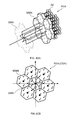
- FIG. 33A an Array Antenna (AR) with Antenna Elements (AE) disposed on a hexagonal lattice according to a third exemplary embodiment of the invention
- FIG. 33B the Array Lattice of the Array Antenna of FIG. 33A ;
- FIG. 34 the relationship between the Sub-Array Lattice ( FIG. 34B ) and the Array Lattice ( FIG. 34A ) of FIG. 33B ;
- FIG. 35A an Elementary Cell induced by the Sub-Array Lattice of FIG. 34B on the Array Lattice of FIG. 34A ;
- FIG. 35B a tiling of the Array Lattice of FIG. 34A by means of the Elementary Cell of FIG. 35A ;
- FIG. 36A an Elementary Cell of the Beams Lattice generated by a MD-DFT based on the Array Lattice and Sub-Array-Lattice of FIG. 34A ;
- FIG. 36B Grating lobes the Beams Lattice of FIG. 36A ;
- FIG. 37 Geometry ( FIG. 37A ) and coordinates vectors ( FIG. 37B ) of the Antenna Elements constituting an Elementary Cell and a Non-Overlapping Sub-Array according to the third design example;
- FIG. 38 Geometry ( FIG. 38A ) and beam-space coordinates vectors ( FIG. 38B ) of the Beams constituting an Elementary Cell of the Beams Lattice generated by a MD-DFT based on the Array Lattice and Sub-Array-Lattice of FIG. 34A ;
- FIG. 39 interconnection of the Multi-Mode Network to the Antenna Elements constituting an Elementary Cell according to said third exemplary embodiment of the invention.
- FIG. 40 Geometry ( FIG. 40A ) and coordinates vectors ( FIG. 40B ) of the Elementary Cells constituting the Array of Sub-Arrays according to said third exemplary embodiment of the invention;
- FIG. 41A a numbering of the Elementary Cells constituting the Array of Sub-Arrays according to FIG. 40 (left), and of the Antenna Elements (AEs) constituting an Elementary Cell (EC) according to FIG. 37 (right);
- FIG. 41B a numbering of the Antenna Elements constituting the Array of Sub-Arrays according to FIG. 41A ;
- FIGS. 42A and 42B a functional diagram of an Overlapping Sub-Array with interconnections of a Single-Mode Network to a Multi-Mode Networks (MMNs) and to Antenna Elements, according to said third exemplary embodiment of the invention;
- FIG. 43 a layout of overall Array and highlight of the Reference Sub-Array corresponding to the Overlapping Sub-Array of FIG. 42A ;
- FIG. 44 an interconnection diagram of a Single-Mode Networks required for each Overlapping Sub-Array according to said third exemplary embodiment of the invention.
- FIG. 45 a set of Single-Mode Networks according to FIG. 44 implemented as a single layer of non-crossing Single-Mode Networks;
- FIGS. 46A and 46B an assembly of the set of non-crossing Single-Mode Networks of FIG. 45 ;
- FIG. 47 an overall layout of the Array Antenna and a Lossless Beamforming Network according to said third exemplary embodiment of the invention.
- FIG. 48 simulated array geometry ( FIG. 48A ) and Sub-Array Radiation Pattern performance for a Non-Overlapping Sub-Array and an Overlapping Sub-Array ( FIG. 48B ) according to said third exemplary embodiment of the invention;
- FIG. 49 a Sub-Array Radiation Pattern performance greyscale map for a Non-Overlapping Sub-Array ( FIG. 49A ) and an Overlapping Sub-Array ( FIG. 49B ) according to said third exemplary embodiment of the invention;
- FIG. 50 a Sub-Array Radiation Pattern performance contour plot for a Non-Overlapping Sub-Array ( FIG. 50A ) and an Overlapping Sub-Array ( FIG. 50B ) according to said third exemplary embodiment of the invention;
- FIG. 51 a scheme illustrating the radiation requirement of an antenna according to the invention.
- FIGS. 52A, 52B and 52C plots illustrating the concepts of Reference Sub-Array Factor (RSAF), Array of Sub-Arrays Factor (ASAF) and Total Array Pattern (TAP).
- RSAF Reference Sub-Array Factor
- ASAF Array of Sub-Arrays Factor
- TAP Total Array Pattern
- matrices will be represented in bold capital letters and vectors in bold lower-case, italics will be used for real variables, vectors and matrices, and regular non-italics for integer variables, vectors and matrices.
- the matrix transpose operator will be indicated as ( . . . ) T , inverse as ( . . . ) ⁇ 1 , and inverse transpose as ( . . . ) ⁇ T .
- the planar array AR is decomposed in a number N SA (where N SA ⁇ N E ) of sub-arrays each composed of groups of antenna elements, all the sub-arrays being exactly identical (each composed of N E SA antenna elements) and translationally arranged on a regular Array of Sub-Arrays (ASA) Lattice.
- N SA where N SA ⁇ N E
- ASA Array of Sub-Arrays
- ASA Array of Sub-Arrays
- the Total Array Pattern TAP(u) may be calculated considering the sub-arrays as individual radiating elements, with a Reference Sub-array Radiation Pattern RSAP(u) which accounts for the Element Pattern EP(u) of the antenna elements, the spatial periodicity RSA and excitation w n RSA of the elements of the reference sub-array, and calculating the Array of Sub-Arrays Factor ASAF(u) which results from the spatial periodicity ASA and excitation w p ASA of the sub-arrays.
- TAP(u) is given by:
- the RSAF shows a relatively broad central peak with sidelobes, while the ASAF is a periodical series of narrow peaks with closely-spaced sidelobes.
- the TAP given by equation 5 and illustrated by FIG. 52C , has a narrow central peak and lower sidelobes.
- the ASAF is determined by a—possibly reconfigurable—Multi-Beam Network (MBN) while the RSAF is determined by a—preferably lossless—network which, as it will be discussed further is factored into a layer of Single-Mode Networks (SMNs) and a layer of Multi-Mode-Networks (MMNs).
- MSN Multi-Beam Network
- MSNs Single-Mode Networks
- MNNs Multi-Mode-Networks
- r and n are column vectors with real and integer entries, respectively:
- a lattice defined by a base vectors matrix D will be indicated as ⁇ (D) (see e.g. FIG. 4B ).
- a sub-lattice of ⁇ (D) can be defined by mean of a non-singular integer matrix M and is given by ⁇ (DM).
- the number M
- is called the index of ⁇ (D) in ⁇ (DM)—see e.g. FIGS. 5A and 5B .
- modulo DM the vector “modulo DM” operation.
- Two vectors x and y on the lattice ⁇ (D) are said to be congruent modulo DM if their difference (x ⁇ y) belongs to ⁇ (DM) (see the paper by Angeletti [22]).
- the modulo DM operation is an equivalence relation (i.e. it satisfies reflexive, symmetric and transitive properties) and can be used to induce on ⁇ (D) a set of equivalence classes (also known as “congruency classes” or “cosets”) in number equal to
- congruency classes also known as “congruency classes” or “cosets”
- Each equivalence class is a shifted version of ⁇ (DM).
- elements designated by a same number (0, 8) belong to a same equivalence class.
- any two equivalence classes defined with the modulo DM operation are either equal or disjoint; consequently the set of all equivalence classes of ⁇ (D), defined with the modulo DM operation, forms a partition of ⁇ (D): every element of ⁇ (D) belongs to one and only one equivalence class.
- ECR( ⁇ (D)/mod DM) also known as “Elementary Cell” C(D/DM)
- ECR( ⁇ (D)/mod DM) is a finite subset of
- the equivalence class representative is, in general, not unique.
- FIG. 6A shows an exemplary 9 -element elementary cell.
- ⁇ ⁇ ( 1 ⁇ ⁇ D ) defines the reciprocal lattice ⁇ ( ⁇ D ⁇ T ) corresponding to the positions of the grating lobes generated by the array lattice AL;
- ⁇ ⁇ ( 1 ⁇ ⁇ DM ) defines the reciprocal lattice ⁇ ( ⁇ (DM) ⁇ T ) corresponding to the positions of the grating lobes generated by the array of sub-arrays lattice ASAL.
- FIGS. 7A and 7B show the lattice of grating lobes of the sub-array of FIG. 6A .
- the sub-lattice of grating lobes relevant to the Array Lattice of FIG. 6A are shown in bold, and numbers 0-8 identify equivalence classes of grating lobes, defined in the same way as the equivalence classes of the antenna elements.
- FIG. 7A shows an elementary cell of the grating lobes relevant to the sub-array of FIG. 6A .
- the number of active control elements is equal to the number of sub-arrays N SA , but the reduction in the number of control elements (from N E to N SA ) implies having a larger periodicity due to the sub-array lattice which leads to the appearance of undesired Grating Lobes (GL) in the ASAF which can be reduced by appropriate design of the SAP.
- the ideal Sub-Array Pattern (supposing identical Sub-Arrays) should have a flat response in the desired Field of View (FOV) and zero outside.
- the Field of View FOV should correspond to a sub-set of the Voronoi region of the lattice ⁇ ( ⁇ (DM) ⁇ T ) defined by the grating lobes of the Sub-Array Lattice.
- An optimal array design jointly exploits the element pattern, the array elements lattice ⁇ (D) and the Sub-Array design (including the definition of the Array of Sub-Arrays Lattice ⁇ (DM)) with the twofold objective of reducing the number of control elements and suppressing the grating lobes of the Array of Sub-Arrays Factor in a desired Grating-Lobes Free Zone (GLFZ) outside of the Field of View (FOV).
- GPFZ Grating-Lobes Free Zone
- FIG. 51 This is illustrated by FIG. 51 , which also reminds that, while the grating lobe structure is dictated by the sub-array geometry, the minimum beam size depends on the overall antenna dimensions.
- the periodicity matrix DM of the Array of Sub-Arrays Lattice ⁇ (DM) allows to partition the array elements in equivalence classes by mean of the vectorial modulo DM operation and to define a Non Overlapping Sub-Array (NOSA) corresponding to an Elementary Cell C(D/DM).
- NOSA Non Overlapping Sub-Array
- the elements of an array constructed this way are automatically partitioned into a number of equivalence classes corresponding to the Elementary Cell.
- the Elementary Cells (ECs) needed to cover the array form the set of positions indicated in the following as Array of Elementary Cells (AEC) which corresponds to a subset of the Array of Sub-Arrays Lattice ⁇ (DM), and include the set of positions of Array of Sub-Arrays (ASA) ASA ⁇ AEC ⁇ ⁇ ( DM ) (17)
- the index l allows numbering each Elementary Cell constituting the array. As a consequence, the position of a generic element of the array is completely defined by a pair of indexes
- n l , m Ml + m ⁇ ⁇ n l , m ⁇ N m ⁇ M l ⁇ L ( 22 )
- the index q allows numbering each Elementary Cell (EC) constituting the Reference Sub-Array (RSA). Similarly to previous discussions, the position of a generic element of the Reference Sub-Array (RSA) is completely defined by a pair of indexes:
- n q , m Mq + m ⁇ ⁇ n q , m ⁇ N ⁇ m ⁇ M q ⁇ Q ( 27 )
- w n RSA w Mq + m RSA ⁇ ⁇ n ⁇ N ⁇ m ⁇ M q ⁇ Q ( 28 )
- a Sub-Array translated to r ⁇ dot over (p) ⁇ ASA is defined on the Array of Elementary Cells,
- the p 1 -th and p 2 -th Sub-Arrays overlap on a number of Elementary Cells whose indexes correspond to the subset of the Array of Elementary Cells, l ⁇ (Q+p 1 ) ⁇ (Q+p 2 ).
- the orthonormality condition can be reformulated as,
- the complex scalar product of the different excitations assumes the form of a complex autocorrelation.
- the orthonormality of the Sub-Arrays, and thus their lossless realisability, corresponds to imposing that the complex spatial autocorrelation of Sub-Array excitations is periodically nullified with a period equal to the Array of Sub-Array Lattice periodicity.
- k can be interpreted as the transfer matrix of a lossless Multi Mode Networks (MMN)—see FIG. 3 .
- a MMN matrix is associated to each Elementary Cell (EC) which constitutes a Non-Overlapping Sub-Array (NOSA).
- the MMN matrix must have a number of input ports at least equal to (or larger than) the number of Elementary Cell forming a Sub-Arrays N EC SA , and the number of output ports at least equal to (or larger than) the number of antenna elements composing the Elementary Cell N E EC .
- k contain all the information relevant to the MMN functionality, nevertheless different network topologies could provide the same transfer characteristic but with very different realization complexity.
- the coefficients can be organized in column vectors c k of size [N E EC ⁇ 1] and the column vectors arranged in a matrix C of size [N E EC ⁇ N E SA ].
- the matrix C can be thought as the transfer part of the scattering matrix of the Multi Mode Network.
- a systematic design procedure for a square network with a number of input/output ports equal to a power of 2 leads to a number of hybrids and of fixed phase shifters equal, respectively, to
- FFT Fast Fourier Transform
- DFT Discrete Fourier Transform
- MD-FFT Multi-Dimensional FFT algorithm
- a planar Non-Overlapping Sub-Array with elements on a periodic lattice ⁇ (D), be defined by the Elementary Cell C(D/DM) of the sub-lattice ⁇ (DM), where D is the non-singular matrix of the inter-element spacings and M is a non-singular integer matrix.
- the Non-Overlapping Sub-Array admits a Multi Dimensional-Discrete Fourier Transform (MD-DFT) whose results are a set of beams pointed in the u,v plane with directions defined by the reciprocal lattice ⁇ ( ⁇ (DM) ⁇ T ).
- MD-DFT Multi Dimensional-Discrete Fourier Transform
- MD-IDFT The inverse (MD-IDFT) is defined on a finite lattice of equal dimension
- x ⁇ ( k ) ⁇ m ⁇ C ⁇ ( I / M ) ⁇ ⁇ X ⁇ ( m ) ⁇ exp ⁇ ( j2 ⁇ ⁇ ⁇ m T ⁇ N - 1 ⁇ k ) ( 46 )
- the MD-DFT is then equivalent to a transfer matrix with the following entries c m
- Each beam input port k of the BFN realizes a different NOSA array factor with steering direction u k :
- MD-DFT offers the possibility of a series of effective implementations known as Multi Dimensional-Fast Fourier Transforms (MD-FFTs).
- the 1D Cooley-Tukey algorithm can be extended with the method described by R. Mersereau and T. Speake as described in, “A unified treatment of Cooley-Tukey algorithms for the evaluation of the multidimensional DFT”, IEEE Transactions on Acoustics, Speech, and Signal Processing, Vol. 29, No 9, pp 1011-1018, October 1981.
- a periodicity matrix D relevant to the Array Lattice (AL) ⁇ (D), is selected in such a way that the Voronoi region (or more generally an elementary cell) of the normalized reciprocal lattice ⁇ ( ⁇ D ⁇ T ) includes the Grating-Lobes Free Zone (GLFZ) of concern.
- a periodicity matrix DM relevant to the Sub-Array Lattice (SAL) ⁇ (DM), is selected in such a way that the Voronoi region (or more generally an elementary cell) of the normalized reciprocal lattice ⁇ ( ⁇ (DM) ⁇ T ) includes the Field of View (FOV) of interest.
- SAL Sub-Array Lattice
- An Overlapping Sub-Array OSA configuration is defined selecting a number of Non Overlapping Sub-Arrays N NOSA OSA (where N NOSA OSA reads as the number of Non-Overlapping Sub-Arrays forming an Overlapping Sub-Array).
- a lossless Multi Mode Network (MMN) and a lossless Single Mode Networks (SMN) are defined such that:
- a Multi-Beam Network is defined for associating each beam port to each Overlapping Sub-Array input port (OSA-IP) through respective weighting units;
- the inventive BFN has one (single-beam case) or more (multi-beam case) beam ports BP for injecting respective beam signal(s), and a plurality of antenna ports AP feeding respective antenna elements organized in a regular one- or two-dimensional lattice (one-dimensional case represented on the figure) which is hierarchically partitioned in a plurality of Non-Overlapping Sub-Arrays (NOSAs) and in a plurality of Overlapping Sub-Arrays (OSAs).
- NOSAs Non-Overlapping Sub-Arrays
- OSAs Overlapping Sub-Arrays
- the BFN architecture is the same for a one- or bi-dimensional array, only the arrangement of antenna elements changes.
- FIG. 3 refers specifically to an emitting antenna.
- the architecture of the BFN remains the same, except that input ports are turned into output ports and vice versa, and that HPAs are suppressed or replaced by low-noise amplifiers connected either to the beam (output) ports or to the output ports of the antenna elements.
- the transfer matrix of the Multi-Mode Network is selected to be a Multi-Dimensional DFT (MD-DFT).
- MD-DFT Multi-Dimensional DFT
- the MD-DFT allows effective implementations known as Multi Dimensional Fast Fourier Transforms (MD-FFTs) (refer to Guessoum and Mersereau [25] and to U.S. Pat. No. 5,812,088 to Coromina et alii [27] and to European Patent No. 2,296,225 to Angeletti for an explanation of this algorithm as applied to radiofrequency phased array antennas).
- MD-FFTs Multi Dimensional Fast Fourier Transforms
- the design step D6) described above can be further elaborated as follows:
- MSN lossless Multi Mode Network
- W N exp ⁇ ( - j ⁇ 2 ⁇ ⁇ N ) , or can be re-conduced to this form through a multiplication for an arbitrary phase factor (i.e. c m
- k exp( ⁇ j ⁇ m )W det
- a lossless Single Mode Networks is defined such that it has a number N OP SMN of output ports (SMN-OP) and an input port (SMN-IP) for associating each overlapping sub-arrays input port (OSA-IP) to a plurality of non-overlapping sub-arrays input ports (NOSA-IP) through weighting transfer matrix coefficient b k ;
- the proposed architecture achieves the same theoretical performance as the prior art (see in particular Borgiotti [4]) in terms of reduction of the number of Weight Elements (WEs) with respect to a “full” BFN with N B ⁇ N E WE. This reduction ranges from 20% to 80%, depending on the mission requirements.
- the present architecture outperforms state-of-the-art architectures in terms reduction of the number of High Power Amplifiers (HPAs) as the amplifiers can be placed at the inputs of the Overlapped Sub-Arrays (SAs) given that the SMN and MMN can be lossless.
- HPAs High Power Amplifiers
- SAs Overlapped Sub-Arrays
- the proposed architecture also outperforms array antennas based on Non-Overlapped Sub-Array with similar number of Sub-Arrays (and in turn similar complexity in number of Weight Elements WEs and High Power Amplifiers HPAs) in terms of scan loss performances within the field of view.
- the lossless condition which imposes additional constraints on the available degree of freedoms in the synthesis of the excitations of the Antenna Elements of an Overlapped Sub-Array, doesn't penalize the scan loss performances within the field of view.
- the Non-Overlapping Sub-Array is composed of 3 ⁇ 3 AEs on a rectangular lattice
- the Multi-Mode Network is based on a 9 ⁇ 9 MD-DFT
- the Overlapped Sub-Array is composed of 9 NOSA
- FIGS. 4 to 18 The details of the synthesis according to the present invention are reported in FIGS. 4 to 18 .
- the scanning performances of the Overlapped Sub-Array are reported in FIGS. 19 to 21 and therein compared with the scanning performances of a Non-Overlapped Sub-Array of similar geometry.
- FIGS. 5A to 7B illustrates the main theoretical concepts at the basis of the invention: Sub-Array Lattice, Elementary Cell, tiling, Beams Lattice, Grating lobes.
- FIG. 8A illustrates an Elementary Cell EC of the Array Antenna AR of FIG. 4A , comprising 9 Antenna Elements disposed on a 3 ⁇ 3 square.
- FIG. 8B represents the corresponding coordinate vectors.
- This Elementary Cell also constitutes a “Non-Overlapping” Sub-Array NOSA.
- FIG. 9A illustrates an Elementary Cell of the Beams Lattice defined by the bi-dimensional Fourier Transform of the Sub-Array Lattice of FIG. 5 .
- FIGS. 10-18 illustrates the implementation of the invention.
- FIG. 10 shows a Multi-Mode Network MMN having 9 input ports and 9 output ports which are connected to the 9 Antenna Elements constituting the Elementary Cell EC of FIG. 7A .
- each input port of the MMN is connected to a respective Single Mode Network (SMN—not represented) while, on the output side, the signal received by each Antenna Element is a linear combination of the input signals of the MMN.
- SSN Single Mode Network
- FIG. 11A represents an Array of Sub-Arrays ARSAEC, each Sub-Array being an Elementary Cell of the type illustrated on FIG. 7A , connected to a respective MMN as illustrated on FIG. 10 .
- FIG. 11B represents the coordinate vectors of the Array of Sub-Arrays.
- FIG. 10A reminds that each of said Sub-Arrays is constituted by 9 Antenna Elements.
- each Antenna Element can be identified by a pair of number, the first one identifying the (Non-Overlapping) Sub-Array to which it belongs, and the second one indicating the position of the element within said Sub-Array.
- element (5,3) is the third element of the fifth Sub-Array.
- FIGS. 13A and 13B represent a Single-Mode Network SMN distributing a signal to nine MMN, each feeding nine respective Antenna Elements forming a Non-Overlapping Sub-Array NOSA (or, equivalently, an Elementary Cell EC).
- the SSM feeds a different port of each MMN: port 0 of MMN n° 0, port 2 of MMN n° 1 etc.
- the set of nine EC—i.e. of 81 Antenna Elements—fed through a same SMN constitutes the Reference Sub-Array RSA, or more generally an Overlapping Sub-Array OSA.
- FIG. 14 shows the RSA within the whole Array Antenna AR.
- the Array Antenna AR comprises 5 Overlapping Sub-Arrays: a first one corresponding to the RSA represented in bold on FIG. 14 and four other obtained by translating the RSA of one unit cell. Otherwise stated, the Overlapping Sub-Array n° 0 is cantered on EC n° 0, the Overlapping Sub-Array n° 1 is cantered on EC n° 1, the Overlapping Sub-Array n° 2 is cantered on EC n° 2, the Overlapping Sub-Array n° 3 is cantered on EC n° 3 and the Overlapping Sub-Array n° 4 is cantered on EC n° 4 (for the numbering of EC, see FIG. 12A ).
- FIG. 15 shows that each Overlapping Sub-Array is fed by a respective SMN; the five SMN form what is called a “set” or “layer” of Single Mode Networks, SSMN.
- FIG. 15 the output connections of the SMNs cross with each other. Therefore, it is useful from an implementation point of view to decompose the SSMN into two subsets without crossing, forming a multilayer assembly; this is illustrated by FIGS. 16 and 17A .
- FIG. 17B represents the SSMN as a single element with five input port (one for each Overlapping Sub-Array) and 45 output ports.
- the number of output ports of the SSMN is set to 189, i.e. equal to the number of input ports of the set of MMNs, which in turn is equal to the number of AE; of these, however, only 45 are “real” output ports, the 144 remaining ones being “dummy” ports.
- FIG. 18 shows the SSMN connected to an arrangement of MMNs (cf. FIG. 15 ) feeding the 189 Antenna Elements of the Array Antenna AR.
- FIGS. 19-21B The technical result of the exemplary embodiment is illustrated on FIGS. 19-21B .
- FIG. 19A recalls the relationship between the Reference Sub-Array RSA (and more generally an Overlapping Sub-Array OSA) and an Elementary Cell EC (i.e. a Non-Overlapping Sub-Array).
- FIG. 19B illustrates the Radiation Pattern of the NOSA (dotted line) and of the OSA (continuous line), cut along a single main axis.
- FIGS. 20A and 20B represent the NOSA and OSA radiation patterns, respectively, in greyscale.
- FIGS. 21A and 21B represent the same radiation patterns as contour plots, wherein numbers on the contour lines correspond to decibels.
- the Non-Overlapping Sub-Array is composed of 3 ⁇ 3 AEs on a rectangular lattice (same as El), the Multi-Mode Network is based on a 9 ⁇ 9 MD-DFT (same as El), and the Overlapped Sub-Array is composed of 5 NOSA.
- Array lattice, Elementary Cell and MD-DFT are the same of the Design Example 1 and the reader can refer to FIGS. 4 to 10 for relevant details.
- FIGS. 22 to 29 The details of the synthesis according to the present invention are reported in FIGS. 22 to 29 .
- the scanning performances of the Overlapped Sub-Array are reported in FIGS. 30 to 32 and therein compared with the scanning performances of a Non-Overlapped Sub-Array of similar geometry.
- FIGS. 22A-32B correspond to FIGS. 11A-21B mutatis mutandis, therefore it is not necessary to discuss them in detail.
- the Non-Overlapping Sub-Array is composed of 7 AEs on a hexagonal lattice
- the Multi-Mode Network is based on a 7 ⁇ 7 MD-DFT
- the Overlapped Sub-Array is composed of 7 NOSA.
- FIGS. 33 to 47 The details of the synthesis according to the present invention are reported in FIGS. 33 to 47 .
- the scanning performances of the Overlapped Sub-Array are reported in FIGS. 48 to 50 and therein compared with the scanning performances of a Non-Overlapped Sub-Array of similar geometry (i.e. composed of 7 AEs on a hexagonal lattice).
- FIGS. 33A-50B correspond to FIGS. 4A-21B mutatis mutandis, therefore it is not necessary to discuss them in detail.
Abstract
Description
-
- a reconfigurable BFN (R-BFN) comprising NB×NSA active weight elements; and
- a fixed passive BFN distributing the signal from each output port of the reconfigurable BFN to a group of Antenna Elements forming a respective Sub-Array (SA).
-
- Skobelev [15] analysed a lossless network consisting in power dividers and directional couplers, whose coupling coefficients may be derived by an optimization process. The network, also known as “chessboard network”, presents the advantage to be lossless from the point of view of Microwave Circuit Theory. Reference [16] discusses improvements in the radiative performances of the “chessboard network”.
- Shelton [17] introduced the concept of Double Transform Network, which consists in using systems able to perform a double Fourier Transform in order to obtain a flat-topped sub-array radiation pattern. Such systems may be realized with constrained networks, lenses and also digitally, preserving the lossless property of the system. Application of the Double Transform method to on-board satellite arrays has been reported in [1].
- DuFort contribution [14] represents another important milestone in the design of beamforming networks for Overlapped Sub-Arrays. It proposes a BFN composed of matched hybrids arranged in cascade, whose coupling coefficients have to be determined in order to approximate an ideal OSA radiation pattern.
- Another interesting contribution to Overlapped Sub-Array techniques is due to Ploussios [19] who designed a BFN architecture valid for both LFOV and multi-beam applications, and also presented an extension to planar arrays.
- Herd [20] proposed an hybrid (analogue/digital) architecture, which is applicable to planar array, however, the BFN doesn't fulfil the lossless property and cannot be used for high power applications.
- Craig and Stirland [21] introduced several embodiments of a new BFN architecture and an optimization method to set the design parameters (distance between radiators, distance between adjacent control points, total number of array radiators and control points . . . ) starting directly from the requirements in terms of radiation properties (Beam-Width, Field Of View, etc.). The proposed BFN may be digital, analogue or hybrid (realized with a combination of digital and analogue devices).
-
- Most prior art BFNs (e.g. [14], [15], [17]) are only designed for linear arrays, while most of the practical applications require the use of planar arrays;
- Some prior art BFNs (e.g. [20], [21]) are not lossless from the point of view of the Microwave Circuit Theory, which forces to place the HPAs at the input ports of the antenna elements, and therefore to use NE of them. Another drawback, in case of HPAs placed at the input ports of the antenna elements, consists in the fact that signals at OSA-OPs may be characterized by different amplitudes (which are set by the BFN), implying that the HPAs have to be operated at a certain Input Power Back-Off (IBO) with respect to saturation. The associated HPA low DC-to-RF power conversion efficiencies, high dissipated powers and need for improved thermal dissipation system put additional stringent constraints to payload feasibility.
- Other prior art BFNs are theoretically lossless but exhibit high complexity (e.g. [14], [15], [19]), and therefore non-negligible implementation losses.
-
- a Multi-Beam Network (MBN), which provides flexibility and can be reconfigurable and/or lossy, for associating beam ports to overlapping sub-arrays (OSAs) through respective weighting elements;
- a layer of (preferably lossless) Single Mode Networks (SMNs), corresponding to respective OSAs; and
- a layer of (preferably lossless) Multi Mode Networks (MMNs), corresponding to respective non-overlapping sub-arrays (NOSAs).
-
- a multi-beam network having at least NB input ports connected to respective beam ports of the beam-forming network and at least NOSA>1 output ports, for associating to each said output port a linear combination of input signals from respective input ports;
- a set of at least NOSA lossless single-mode networks, each having an input port connected to a respective output port of said multi-beam network and at least NOSA NOSA>1 output ports, for associating to each said output port a signal obtained by weighting an input signal from said input port; and
- a set of at least NNOSA lossless multi-mode networks, each having at least NOSA NOSA NNOSA OSA input ports, each one connected to an output port of a respective single-mode network, and at least NE NOSA>NNOSA OSA output ports connected to respective antenna ports of the beam-forming network, for associating to each said output port a linear combination of input signals from respective input ports.
-
- a set of at least NNOSA>1 lossless multi-mode networks, each having at least NE NOSA>1 input ports connected to respective antenna ports of the beam-forming network, and at least NNOSA OSA>1 NOSA NOSA>1 output ports, for associating to each said output port a linear combination of input signals from respective input ports;
- a set of at least NOSA lossless single-mode networks, each having at least NNOSA OSA NOSA NOSA input ports connected to respective output ports of respective multi-mode networks and an output port, for associating to said output port a signal obtained by weighting an input signal from said input ports; and
- a multi-beam network having at least NOSA input ports connected to the output ports of respective single-mode networks and at least NB output ports connected to respective beam ports of the beam-forming network, for associating to each said output port a linear combination of input signals from respective input ports.
A={r n :n=0 . . . (N E−1)} (1)
RSA={r n RSA :n=0 . . . (N E SA−1)}⊂ A (2)
ASA={r p RSA :p=0 . . . (N SA−1)}⊂ A (3)
and identical sub-arrays, characterized by the same number of radiating elements (NE SA) and the same set of excitations, the Total Array Pattern TAP(u) may be calculated considering the sub-arrays as individual radiating elements, with a Reference Sub-array Radiation Pattern RSAP(u) which accounts for the Element Pattern EP(u) of the antenna elements, the spatial periodicity RSA and excitation wn RSA of the elements of the reference sub-array, and calculating the Array of Sub-Arrays Factor ASAF(u) which results from the spatial periodicity ASA and excitation wp ASA of the sub-arrays.
where,
R and Z being the sets of real and relative numbers, respectively; while D is composed of two non-linearly-dependent real column vectors which constitute the lattice base and define the inter-element spacing,
and rn=Dnn expresses the position of a radiating element of the array.
N=D −1 A⊂Λ(I) (8)
A⊂Λ(D)≡AL (9)
ASA⊂Λ(DM)≡ASAL (10)
which is the product of the element radiation pattern EP(u) times the array factor AF(θ,φ)=AF(u),
where we have exploited the definition of the scalar product,
(D −T k k)·(Dn n)=k k T D −1 Dn n =k k T n n (14)
as well as the fact that having kk and nn integer entries, exp(−j2πkk Tnn) results to be always equal to unit.
-
- the periodicity matrix D relevant to the Array Lattice AL normalized to the wavelength λ,
defines the reciprocal lattice Λ(λD−T) corresponding to the positions of the grating lobes generated by the array lattice AL;
-
- similarly, the periodicity matrix DM relevant to the Array of Sub-Arrays Lattice ASAL, normalized to the wavelength λ,
defines the reciprocal lattice Λ(λ(DM)−T) corresponding to the positions of the grating lobes generated by the array of sub-arrays lattice ASAL.
and exhibiting side fronts as steep as possible.
NOSA={r m NOSA :m=0 . . . (N E NOSA−1)}⊂≡C(D/DM)⊂Λ(D) (15)
M=C(I/M)=D −1 C(D/DM) (16)
ASA⊂AEC⊂Λ(DM) (17)
AEC={r 1 AEC:1=0 . . . (N EC−1)}⊂Λ(DM) (18)
L=(DM)−1AEC (19)
P=(DM)−1ASA (20)
-
- the first, l, identifies a unique Elementary Cell.
- the second, m, identifies the antenna equivalence class and the position of the element within an Elementary Cell.
or equivalently,
RSA={r n RSA :n=0 . . . (N E SA−1)}⊂ A (23)
Ñ=D −1RSA⊂ N (24)
ARSAEC={rq ARSAEC :q=0 . . . (N EC SA−1)}⊂AEC⊂Λ(DM) (25)
-
- the first, q, identifies a unique Elementary Cell within the Reference Sub-Array (RSA)
- the second, m, identifies the antenna equivalence class and the position of the element within an Elementary Cell.
or equivalently,
These notations allow a Cartesian indexing of the elements of the array A as well as of the Reference Sub-Array RSA.
where it is introduced the change of variables, Δp=p2−p1, l′=l−p1.
w M q+m RSA =b q c m|q mεM;qεQ (37)
with cm|q satisfying the normalization condition,
with the additional normalization condition on bq,
N EC SA ≦N E EC =M (43)
CC H =I (44)
while a non-factorized N×N BFN is composed by ˜N2 power dividers and phase shifters. This complexity reduction is directly equivalent to that obtained, in the field of digital signal processing, by using the Fast Fourier Transform (FFT) algorithm to evaluate the Discrete Fourier Transform (DFT), and indeed the Butler matrix can be seen as an analog implementation of the FFT.
c m|k=exp(−j2πm T N −1 k)=W det|M| m
The equation above can be rearranged as follows:
u k=λ(k T(M −1 D −1))T =λD −T M −T k kεC(I/M T) (49)
BL=λD −T M −T C(I/M T) (50)
c k
-
- The number NOP MMN of output ports (MMN-OPs) and the number NIP MMN of input ports (MMN-IPs) of the lossless Multi Mode Network (MMN) satisfy the relations NE NOSA≦NOP MMN≦M and NNOSA OSA≦NIP MMN≦M; preferably NOP MMN=NE NOSA=M, and NIP MMN=NNOSA OSA≦M.
- The lossless Single Mode Networks (SMNs) have a number NOP SMN of output ports (SMN-OPs) and input ports (SMN-IPs) for associating each overlapping sub-arrays input port (OSA-IP) to a plurality of non-overlapping sub-arrays input ports (NOSA-IPs) through weighting transfer matrix coefficient bk;
- Each Single Mode Networks (SMN) feeds NNOSA OSA≦M Non Overlapping Sub-Arrays (NOSAs) constituting an Overlapping Sub-Arrays (OSAs). To maintain the orthogonality and the lossless condition under translation of the Overlapped Sub-Array, the output ports of a lossless Single Mode Networks (SMN-OPs) must be connected to different homologue input ports of the lossless Multi Mode Networks (MMN-IPs). To better clarify this point this means that if a Single Mode Network (SMN) is interconnected to an ordered input port of one of the lossless Multi Mode Networks (MMNs), the interconnections of the remaining lossless Multi Mode Networks (MMNs) to the same Single Mode Network (SMN) will not reuse a homologue ordered input port. This can be mathematically formulated indicating that the interconnection relationship between the k-th used port of the q-th MMN composing the Reference Overlapped Sub-Array must be in the form of a permutation;
k=Π(q) (52)
where Π(q) is the permutation array that indicates which column Π(q) of the MMN transfer matrix cm|k is picked for the q-th Non-Overlapping Sub-Array of the Reference Overlapping Sub-Array (RSA). - The coefficients bq and cm|k of the transfer matrices of the lossless Single Mode Network (SMN) and of the lossless Multi Mode Network (MMN), respectively, are determined such as to satisfy the lossless condition:
together with the target to optimize the Sub-Array Pattern SAP(u) such to have a flat response in the desired Field of View (FOV) and zero outside, where:
-
- The number NIP MBN of input ports (MBN-IP) is equal or larger than the number of independent beams NB to be generated NIP MBN≧NB, preferably NIP MBN=NB;
- The number NOP MBN of output ports (MMN-OP) is equal or larger than the number of Overlapped Sub-Arrays NOSA composing the antenna, NOP MBN≧NOSA, preferably NOP MBN=NOSA;
- The coefficients ap|i of the transfer matrix of the Multi-Beam Network (MBN) for the i-th beam are determined such to optimise the Total Array Pattern TAPi(u) for the i-th beam, where:
TAPi(u)=SAP(u)ASAFi(u) (56)
-
- A Multi-Beam Network (MBN)—which connects each BP to several OSA input ports (OSA-IPs) through respective weighting units;
- A plurality of lossless Single Mode Networks (SMNs)—which connect each OSA-IP to a plurality of NOSA-IPs through respective weighting units; and
- A plurality of lossless Multi Mode Networks (MMNs)—each associated to a NOSA and having a number of input ports at least equal to (or larger than) the number of NOSA-IPs and the number of output ports at least equal to (or larger than) the number of AEs composing the NOSAs.
-
- The network has a number NOP MMN of output ports (MMN-OP) equal to the number of elements of an Elementary Cell NOP MMN=M;
- The network has a number NIP MMN of input ports (MMN-IP) satisfying the relation NNOSA OSA≦NIP MMN≦M; preferably NIP MMN=NNOSA OSA≦M.
- The coefficients cm|k of the transfer matrix of the lossless Multi Mode Network (MMN) are defined accordingly to a Multi-Dimensional DFT (MD-DFT):
c m|k =W det|M| mT M−T k (58)
where
or can be re-conduced to this form through a multiplication for an arbitrary phase factor (i.e. cm|k=exp(−jφm)Wdet|M| m
-
- Each Single Mode Networks (SMN) feeds NNOSA OSA≦M Non-Overlapping Sub-Arrays (NOSA) constituting a
- Given the transfer matrices of the lossless Multi Mode Network (MMN) cm|k the coefficients bq of the transfer matrix of the lossless Single Mode Network (SMN) and the interconnection k=Π(q) between the k-th used port of the q-th MMN composing the Reference Overlapped Sub-Array are determined with the target of optimizing the Sub-Array Pattern SAP(u) such to have a flat response in the desired Field of View (FOV) and zero outside.
- [1] G. Toso, P. Angeletti, A Method of Designing and Manufacturing an Array Antenna, U.S. Pat. No. 7,797,816.
- [2] G. Ruggerini, G. Bellaveglia, G. Toso, P. Angeletti, Multibeam Active Aperiodic Lens, European Patent Application EP2090995.
- [3] W. Patton, “Limited Scan Arrays”, in Phased Array Antennas: Proc. 1970 Phased Array Symposium, A. A. Oliner and G. A. Knittel, Eds. Artech House, pp. 254-270, 1972.
- [4] G. Borgiotti, “Degrees of freedom of an antenna scanned in a limited sector”, IEEE International Symposium, pp. 319-320, 1975.
- [5] J. Stangel, “A basic theorem concerning the Electronic scanning capabilities of antennas”,
URSI Commission 6, spring meeting, June 1974. - [6] M. C. Viganó, G. Toso, C. Mangenot, “Direct Radiating Arrays With Quasi-Flat-Top Pattern Sub-Arrays”, 29th ESA Antenna Workshop on Multiple Beams and Reconfigurable Antennas, 18-20 Apr. 2007.
- [7] S. P. Skobelev, “Methods of constructing optimum phased-array antennas for limited field of view”, IEEE Antennas Propagation Magazine, Vol. 40, No. 2, pp. 39-49, April 1998.
- [8] R. J. Mailloux, P. R. Caron, “A class of phase interpolation circuits for scanning phased arrays”, IEEE Trans., Vol. AP-18, No. 1, pp. 114-116, January 1970.
- [9] R. J. Mailloux and P. R. Franchi, Phased Array Antenna with Array Elements Coupled to Form a Multiplicity of Overlapped Subarrays, U.S. Pat. No. 3,938,160, 1976.
- [10] R. J. Mailloux, “An Overlapped Subarray for Limited Scan Application”, IEEE Transactions on Antennas and Propagation, Vol. 22, No. 3, pp. 487-489, March 1974.
- [11] R. J. Mailloux, L. Zahn, A. Martinez, and G. Forbes, “Grating Lobe Control in Limited Scan Arrays”, IEEE Transactions on Antennas and Propagation, Vol. 27, No. 1, pp. 79-85, January 1979.
- [12] R. J. Mailloux, “Synthesis of Spatial Filters with Chebyshev Characteristics”, IEEE Transactions on Antennas and Propagation, Vol. 24, No. 2, pp. 174-181, March 1976.
- [13] P. R. Franchi and R. J. Mailloux, “Theoretical and Experimental Study of Metal Grid Angular Filters for Sidelobe Suppression”, IEEE Transactions on Antennas and Propagation, Vol. 31, No. 3, pp. 445-10 450, May 1983.
- [14] E. C. DuFort, Limited Scan Phased Array System, U.S. Pat. No. 4,228,436.
- [15] S. P. Skobelev, “Analysis and Synthesis of an Antenna Array with Sectoral Partial Radiation Patterns”, Telecommunications and Radio Engineering, Vol. 45, pp. 116-119, November 1990.
- [16] D. Petrolati, P. Angeletti, A. Morini, G. Toso, “Skobelev Network Optimization by Sequential Quadratic Programming”, Electronics Letters, Vol. 46, No. 8, pp. 553-554, April 2010.
- [17] J. P. Shelton, “Multiple Feed Systems for Objectives”, IEEE Transactions on Antennas and Propagation, Vol. 13, pp. 992-994, November 1965.
- [18] D. Betancourt, P. Angeletti, C. del Rio Bocio, “Bea Forming Networks Design Using Bi-dimensional Double Fast Fourier Transforms”, Proceedings of the 26th AIAA International Communications Satellite Systems Conference (ICSSC 2008), San Diego (California), USA, 10-12 Jun. 2008.
- [19] G. Ploussios, Large element antenna array with grouped overlapped apertures, U.S. Pat. No. 4,257,050.
- [20] Jeffrey S. Herd et al, “Design Considerations and Results for an Overlapped Sub-array Radar Antenna”, Proceedings of the 2005 IEEE Aerospace Conference, pp. 1087-1092, 2005.
- [21] A. D. Craig, S. J. Stirland, System for Simplification of Reconfigurable Beam-Forming Network Processing Within a Phased Array Antenna for a Telecommunication Satellite, WO 2009/013527.
- [22] P. Angeletti, “Simple Implementation of Vectorial Modulo Operation based on Fundamental Parallelepiped”. Electronics Letters, Vol. 48, No. 3, pp. 159-160, doi: 10.1049/el.2011.3667, 2 Feb. 2012.
- [23] J. L. Butler, Multiple beam antenna system employing multiple directional couplers in the leadin, U.S. Pat. No. 3,255,450.
- [24] R. Mersereau, T. Speake, “A unified treatment of Cooley-Tukey algorithms for the evaluation of the multidimensional DFT”, IEEE Transactions on Acoustics, Speech, and Signal Processing, Vol. 29, No. 9, pp. 1011-1018, October 1981.
- [25] A. Guessoum, R. Mersereau, “Fast algorithms for the multidimensional discrete Fourier transform”, IEEE Transactions on Acoustics, Speech, and Signal Processing, Vol. 34, No. 4, pp. 937-943, August 1986.
- [26] R. Bernardini, G. Cortelazzo, G. Mian, “A new technique for twiddle factor elimination in multidimensional FFT's”, IEEE Transactions on Signal Processing, Vol. 42, No. 8, pp. 2176-2178, August 1994.
- [27] F. Coromina, J. Ventura-Traveset, M. Yarwood, W. Bosch, Beam forming network for radiofrequency antennas, U.S. Pat. No. 5,812,088.
- [28] P. Angeletti, Reconfigurable Beam-Forming-Network Architecture, European Patent No. 2,296,225; US Patent Application No. 2011/0102263.
Claims (13)
Applications Claiming Priority (1)
| Application Number | Priority Date | Filing Date | Title |
|---|---|---|---|
| PCT/IB2012/002977 WO2014080240A1 (en) | 2012-11-26 | 2012-11-26 | Beam-forming network for an array antenna and array antenna comprising the same |
Publications (2)
| Publication Number | Publication Date |
|---|---|
| US20150341098A1 US20150341098A1 (en) | 2015-11-26 |
| US9374145B2 true US9374145B2 (en) | 2016-06-21 |
Family
ID=47748666
Family Applications (1)
| Application Number | Title | Priority Date | Filing Date |
|---|---|---|---|
| US14/646,753 Active US9374145B2 (en) | 2012-11-26 | 2012-11-26 | Beam-forming network for an array antenna and array antenna comprising the same |
Country Status (4)
| Country | Link |
|---|---|
| US (1) | US9374145B2 (en) |
| EP (1) | EP2923412B1 (en) |
| JP (1) | JP2016506108A (en) |
| WO (1) | WO2014080240A1 (en) |
Cited By (9)
| Publication number | Priority date | Publication date | Assignee | Title |
|---|---|---|---|---|
| US20150349421A1 (en) * | 2014-05-30 | 2015-12-03 | King Fahd University Of Petroleum And Minerals | Millimeter (mm) wave switched beam antenna system |
| US20160301463A1 (en) * | 2015-04-10 | 2016-10-13 | Space Systems/Loral, Llc | Broadband satellite payload architecture |
| US10270524B2 (en) | 2014-04-15 | 2019-04-23 | Space Systems/Loral, Llc | Broadband satellite payload architecture |
| RU2731604C1 (en) * | 2019-06-17 | 2020-09-04 | Российская Федерация, от имени которой выступает Министерство обороны Российской Федерации | Method of constructing a beam-forming system for an active phased antenna array |
| RU2762240C1 (en) * | 2021-05-04 | 2021-12-16 | Публичное акционерное общество "Радиофизика" | Excitation device of planar overlapping subarrays with contour directional diagrams |
| US20220021125A1 (en) * | 2020-07-17 | 2022-01-20 | Huawei Technologies Co., Ltd. | Systems and methods for beamforming using integrated configurable surfaces in antenna |
| RU2774214C1 (en) * | 2021-05-31 | 2022-06-16 | Сергей Евгеньевич Мищенко | Method for building a beam formation system of a receiving digital antenna array |
| US11502418B2 (en) * | 2018-06-05 | 2022-11-15 | European Space Agency | Network for forming multiple beams from a planar array |
| US11916631B2 (en) | 2020-01-09 | 2024-02-27 | Viasat, Inc. | Multi-beam phased array antenna with disjoint sets of subarrays |
Families Citing this family (31)
| Publication number | Priority date | Publication date | Assignee | Title |
|---|---|---|---|---|
| US8817678B2 (en) | 2011-10-17 | 2014-08-26 | Golba Llc | Method and system for centralized or distributed resource management in a distributed transceiver network |
| US9226092B2 (en) | 2012-08-08 | 2015-12-29 | Golba Llc | Method and system for a distributed configurable transceiver architecture and implementation |
| US11855680B2 (en) * | 2013-09-06 | 2023-12-26 | John Howard | Random, sequential, or simultaneous multi-beam circular antenna array and beam forming networks with up to 360° coverage |
| JP6494755B2 (en) * | 2014-10-28 | 2019-04-03 | フラウンホッファー−ゲゼルシャフト ツァ フェルダールング デァ アンゲヴァンテン フォアシュンク エー.ファオ | Antenna device with adjustable antenna beam direction |
| US9848370B1 (en) * | 2015-03-16 | 2017-12-19 | Rkf Engineering Solutions Llc | Satellite beamforming |
| US10158173B2 (en) * | 2015-05-29 | 2018-12-18 | Huawei Technologies Co., Ltd. | Orthogonal-beam-space spatial multiplexing radio communication system and associated antenna array |
| US10148009B2 (en) * | 2015-11-23 | 2018-12-04 | Huawei Technologies Co., Ltd. | Sparse phase-mode planar feed for circular arrays |
| DE102015223482B4 (en) * | 2015-11-26 | 2021-02-25 | Ihp Gmbh - Innovations For High Performance Microelectronics / Leibniz-Institut Für Innovative Mikroelektronik | Millimeter wave antenna module |
| CN105680182A (en) * | 2015-12-11 | 2016-06-15 | 中国电子科技集团公司信息科学研究院 | Array antenna |
| DE102015226026A1 (en) * | 2015-12-18 | 2017-06-22 | Ihp Gmbh - Innovations For High Performance Microelectronics/Leibniz-Institut Für Innovative Mikroelektronik | antenna field |
| US10171139B1 (en) | 2016-02-02 | 2019-01-01 | Ethertronics, Inc. | Inter-dwelling signal management using reconfigurable antennas |
| US9923712B2 (en) | 2016-08-01 | 2018-03-20 | Movandi Corporation | Wireless receiver with axial ratio and cross-polarization calibration |
| CN106199529B (en) * | 2016-08-19 | 2018-08-21 | 西安电子科技大学 | The aerial array setting method of minimal redundancy MIMO radar |
| US10199717B2 (en) | 2016-11-18 | 2019-02-05 | Movandi Corporation | Phased array antenna panel having reduced passive loss of received signals |
| US10014887B1 (en) * | 2017-02-14 | 2018-07-03 | Movandi Corporation | Outphasing transmitters with improved wireless transmission performance and manufacturability |
| US10181866B2 (en) * | 2017-02-14 | 2019-01-15 | Movandi Corporation | Multi-beam outphasing transmitters |
| US10355770B2 (en) | 2017-02-14 | 2019-07-16 | Movandi Corporation | Wireless communications system including an omnidirectional broad-beam relay RF transmitter |
| US10298275B2 (en) | 2017-02-14 | 2019-05-21 | Movandi Corporation | Outphasing transmit and receive wireless systems having dual-polarized antennas |
| US10321332B2 (en) | 2017-05-30 | 2019-06-11 | Movandi Corporation | Non-line-of-sight (NLOS) coverage for millimeter wave communication |
| US10484078B2 (en) | 2017-07-11 | 2019-11-19 | Movandi Corporation | Reconfigurable and modular active repeater device |
| US10348371B2 (en) | 2017-12-07 | 2019-07-09 | Movandi Corporation | Optimized multi-beam antenna array network with an extended radio frequency range |
| US10862559B2 (en) | 2017-12-08 | 2020-12-08 | Movandi Corporation | Signal cancellation in radio frequency (RF) device network |
| US10090887B1 (en) | 2017-12-08 | 2018-10-02 | Movandi Corporation | Controlled power transmission in radio frequency (RF) device network |
| US11088457B2 (en) | 2018-02-26 | 2021-08-10 | Silicon Valley Bank | Waveguide antenna element based beam forming phased array antenna system for millimeter wave communication |
| US10637159B2 (en) | 2018-02-26 | 2020-04-28 | Movandi Corporation | Waveguide antenna element-based beam forming phased array antenna system for millimeter wave communication |
| IT201800008200A1 (en) | 2018-08-28 | 2020-02-28 | Space Eng Spa | Directional waveguide coupler, beamforming network and array antenna including said coupler |
| EP3758148A1 (en) | 2019-06-25 | 2020-12-30 | Nokia Solutions and Networks Oy | An antenna having controlled directivity |
| WO2021062540A1 (en) * | 2019-09-30 | 2021-04-08 | Macdonald, Dettwiler And Associates Corporation | Direct radiating array antenna |
| CN110957579B (en) * | 2019-12-18 | 2021-05-04 | 中国电子科技集团公司第二十研究所 | Reconfigurable overlapping subarray antenna based on MEMS switch matrix |
| GB2597269A (en) * | 2020-07-17 | 2022-01-26 | Nokia Shanghai Bell Co Ltd | Antenna apparatus |
| CN116318278B (en) * | 2023-05-16 | 2023-09-08 | 广东盛路通信科技股份有限公司 | Multi-beam forming network and six-beam base station antenna |
Citations (17)
| Publication number | Priority date | Publication date | Assignee | Title |
|---|---|---|---|---|
| US3255450A (en) | 1960-06-15 | 1966-06-07 | Sanders Associates Inc | Multiple beam antenna system employing multiple directional couplers in the leadin |
| US3736592A (en) * | 1972-05-25 | 1973-05-29 | Us Navy | Multiple beam retrodirective array with circular symmetry |
| US3938160A (en) | 1974-08-07 | 1976-02-10 | Mcdonnell Douglas Corporation | Phased array antenna with array elements coupled to form a multiplicity of overlapped sub-arrays |
| US4228436A (en) | 1978-04-03 | 1980-10-14 | Hughes Aircraft Company | Limited scan phased array system |
| US4257050A (en) | 1978-02-16 | 1981-03-17 | George Ploussios | Large element antenna array with grouped overlapped apertures |
| US4692768A (en) * | 1982-10-26 | 1987-09-08 | Thomson Csf | Feed device for a sweep beam array antenna |
| US5179386A (en) * | 1986-08-21 | 1993-01-12 | Rudish Ronald M | Cylindrical phased array antenna system to produce wide open coverage of a wide angular sector with high directive gain and strong capability to resolve multiple signals |
| US5812088A (en) | 1994-12-19 | 1998-09-22 | Agence Spatiale Europeenne | Beam forming network for radiofrequency antennas |
| US6057806A (en) * | 1998-06-19 | 2000-05-02 | Marconi Aerospace Systems Inc. | Cross-polarized around-tower cellular antenna systems |
| US6559797B1 (en) | 2001-02-05 | 2003-05-06 | Hughes Electronics Corporation | Overlapping subarray patch antenna system |
| US20040160374A1 (en) * | 2003-02-13 | 2004-08-19 | Martin Johansson | Feed network for simultaneous generation of narrow and wide beams with a rotational-symmetric antenna |
| WO2007103589A2 (en) | 2006-03-07 | 2007-09-13 | Massachusetts Institute Of Technology | Multi-beam tile array module for phased array systems |
| WO2009013527A1 (en) | 2007-07-20 | 2009-01-29 | Astrium Limited | System for simplification of reconfigurable beam-forming network processing within a phased array antenna for a telecommunications satellite |
| EP2090995A1 (en) | 2008-02-18 | 2009-08-19 | Agence Spatiale Europeenne | A method of designing and manufacturing an array antenna |
| US7705779B2 (en) * | 2004-10-15 | 2010-04-27 | Interdigital Technology Corporation | Wireless communication apparatus for determining direction of arrival information to form a three-dimensional beam used by a transceiver |
| US7797816B2 (en) | 2008-02-21 | 2010-09-21 | Agence Spatiale Europeenne | Method of designing and manufacturing an array antenna |
| EP2296225A1 (en) | 2009-09-10 | 2011-03-16 | Agence Spatiale Européenne | Reconfigurable beam-forming-network architecture. |
Family Cites Families (2)
| Publication number | Priority date | Publication date | Assignee | Title |
|---|---|---|---|---|
| US6268835B1 (en) * | 2000-01-07 | 2001-07-31 | Trw Inc. | Deployable phased array of reflectors and method of operation |
| CN101320846B (en) * | 2008-06-24 | 2011-12-14 | 东南大学 | Substrate integration wave-guide multi-beam intelligent antenna |
-
2012
- 2012-11-26 WO PCT/IB2012/002977 patent/WO2014080240A1/en active Application Filing
- 2012-11-26 JP JP2015543530A patent/JP2016506108A/en active Pending
- 2012-11-26 EP EP12826602.0A patent/EP2923412B1/en active Active
- 2012-11-26 US US14/646,753 patent/US9374145B2/en active Active
Patent Citations (18)
| Publication number | Priority date | Publication date | Assignee | Title |
|---|---|---|---|---|
| US3255450A (en) | 1960-06-15 | 1966-06-07 | Sanders Associates Inc | Multiple beam antenna system employing multiple directional couplers in the leadin |
| US3736592A (en) * | 1972-05-25 | 1973-05-29 | Us Navy | Multiple beam retrodirective array with circular symmetry |
| US3938160A (en) | 1974-08-07 | 1976-02-10 | Mcdonnell Douglas Corporation | Phased array antenna with array elements coupled to form a multiplicity of overlapped sub-arrays |
| US4257050A (en) | 1978-02-16 | 1981-03-17 | George Ploussios | Large element antenna array with grouped overlapped apertures |
| US4228436A (en) | 1978-04-03 | 1980-10-14 | Hughes Aircraft Company | Limited scan phased array system |
| US4692768A (en) * | 1982-10-26 | 1987-09-08 | Thomson Csf | Feed device for a sweep beam array antenna |
| US5179386A (en) * | 1986-08-21 | 1993-01-12 | Rudish Ronald M | Cylindrical phased array antenna system to produce wide open coverage of a wide angular sector with high directive gain and strong capability to resolve multiple signals |
| US5812088A (en) | 1994-12-19 | 1998-09-22 | Agence Spatiale Europeenne | Beam forming network for radiofrequency antennas |
| US6057806A (en) * | 1998-06-19 | 2000-05-02 | Marconi Aerospace Systems Inc. | Cross-polarized around-tower cellular antenna systems |
| US6559797B1 (en) | 2001-02-05 | 2003-05-06 | Hughes Electronics Corporation | Overlapping subarray patch antenna system |
| US20040160374A1 (en) * | 2003-02-13 | 2004-08-19 | Martin Johansson | Feed network for simultaneous generation of narrow and wide beams with a rotational-symmetric antenna |
| US7705779B2 (en) * | 2004-10-15 | 2010-04-27 | Interdigital Technology Corporation | Wireless communication apparatus for determining direction of arrival information to form a three-dimensional beam used by a transceiver |
| WO2007103589A2 (en) | 2006-03-07 | 2007-09-13 | Massachusetts Institute Of Technology | Multi-beam tile array module for phased array systems |
| WO2009013527A1 (en) | 2007-07-20 | 2009-01-29 | Astrium Limited | System for simplification of reconfigurable beam-forming network processing within a phased array antenna for a telecommunications satellite |
| EP2090995A1 (en) | 2008-02-18 | 2009-08-19 | Agence Spatiale Europeenne | A method of designing and manufacturing an array antenna |
| US7797816B2 (en) | 2008-02-21 | 2010-09-21 | Agence Spatiale Europeenne | Method of designing and manufacturing an array antenna |
| EP2296225A1 (en) | 2009-09-10 | 2011-03-16 | Agence Spatiale Européenne | Reconfigurable beam-forming-network architecture. |
| US20110102263A1 (en) | 2009-09-10 | 2011-05-05 | Agence Spatiale Europeenne | Reconfigurable beam-forming-network architecture |
Non-Patent Citations (22)
| Title |
|---|
| Angeletti, P., Simple Implementation of Vectorial Modulo Operation Based on Fundamental Parallelepiped, Electronics Letters, vol. 48, No. 3, (Feb. 2, 2012) 159-160. |
| Bernardini, G. et al., A New Technique for Twiddle Factor Elimination in Multidimensional FFT's, IEEE Transactions on Signal Processing, vol. 42, No. 8 (Aug. 1994) 2176-2178. |
| Betancourt, D. et al., Bea Forming Networks Design Using Bi-Dimensional Double Fast Fourier Transforms, Proceedings of the 26th AIAA International Communications Satellite Systems Conference (ICSSC 2008), San Diego, CA, USA (Jun. 10-12, 2008). |
| Borgiotti, G., Degrees of Freedom of an Antenna Scanned in a Limited Sector, IEEE International Symposium (1975) 319-320. |
| Bradley, A. G., Methods of Selecting Receive Beam Positions in Multiple Beam Forming Antenna Systems, IEEE Transactions on Antennas and Propagation, vol. AP-14, No. 3, (May 1, 1966) 260-266. |
| Franchi, P. R. et al., Theoretical and Experimental Study of Metal Grid Angular Filters for Sidelobe Suppression, IEEE Transactions on Antennas and Propagation, vol. 31, No. 3, (May 1983) 445-10 450. |
| Guessoum, A. et al., Fast Algorithms for the Multidimensional Discrete Fourier Transform, IEEE Transactions on Acoustics, Speech, and Signal Processing, vol. 34, No. 4 (Aug. 1986), 937-943. |
| Herd, J. S. et al., Design Considerations and Results for an Overlapped Sub-Array Radar Antenna, Proceedings of the 2005 IEEE Aerospace Conference (2005) 1087-1092. |
| International Search Report and Written Opinion for Application No. PCT/IB2012/002977 dated Jul. 24, 2013. |
| Mailloux, R. J. et al., A Class of Phase Interpolation Circuits for Scanning Phased Arrays, IEEE Trans., vol. AP-18 (Jan. 1970) 114-116. |
| Mailloux, R. J. et al., Grating Lobe Control in Limited Scan Arrays, IEEE Transactions on Antennas and Propagation, vol. 27, No. 1 (Jan. 1979) 79-85. |
| Mailloux, R. J., An Overlapped Subarray for Limited Scan Application, IEEE Transactions on Antennas and Propagation, vol. 22, No. 3 (Mar. 1974) 487-489. |
| Mailloux, R. J., Synthesis of Spatial Filters With Chebyshev Characteristics, IEEE Transactions on Antennas and Propagation, vol. 24, No. 2 (Mar. 1976) 174-181. |
| Mersereau, R. et al., A Unified Treatment of Cooley-Tukey Algorithms for the Evaluation of the Multidimensional DFT, IEEE Transactions on Acoustics, Speech, and Signal Processing, vol. 29, No. 9 (Oct. 1981) 1011-1018. |
| Patton, W., Limited Scan Arrays, Phase Array Antennas: Proc. 1970 Phased Array Symposium, A. A. Oliner and G.A. Knittel, Eds. Artech House (1972) 254-270. |
| Petrolati, P. et al., Skobelev Network Optimization by Sequential Quadratic Programming, Electronics Letters, vol. 46, No. 8 (Apr. 2010) 553-554. |
| Shelton, J. P., Multiple Feed Systems for Objectives, IEEE Transactions on Antennas and Propagation, vol. 13 (Nov. 1965) 992-994 |
| Skobelev, S. P., Analysis and Synthesis of an Antenna Array With Sectoral Partial Radiation Patterns, Telecommunications and Radio Engineering, vol. 45 (Nov. 1990) 116-119. |
| Skobelev, S. P., Methods of Constructing Optimum Phased-Array Antennas for Limited Field of View, IEEE Antennas Propagation Magazine, vol. 4, No. 2 (Apr. 1998) 39-49. |
| Stangel, J., A Basic Theorem Concerning the Electronic Scanning Capabilities of Antennas, URSI Commission 6, Spring Meeting (Jun. 1974). |
| Vigano, M. C. et al., Direct Radiating Arrays With Quasi-Flat-Top Pattern Sub-Arrays, 29th ESA Antenna Workshop on Multiple Beams and Reconfigurable Antennas, (Apr. 18-20, 2007). |
| Wong, M. S. et al., A Multiple Beam Antenna With Simultaneous Independent Beams Over Limited Scan Sectors, Antennas and Propagation Society International Symposium (Oct. 15, 1976) 314-319. |
Cited By (12)
| Publication number | Priority date | Publication date | Assignee | Title |
|---|---|---|---|---|
| US10270524B2 (en) | 2014-04-15 | 2019-04-23 | Space Systems/Loral, Llc | Broadband satellite payload architecture |
| US20150349421A1 (en) * | 2014-05-30 | 2015-12-03 | King Fahd University Of Petroleum And Minerals | Millimeter (mm) wave switched beam antenna system |
| US9692126B2 (en) * | 2014-05-30 | 2017-06-27 | King Fahd University Of Petroleum And Minerals | Millimeter (mm) wave switched beam antenna system |
| US10374309B2 (en) * | 2014-05-30 | 2019-08-06 | King Fahd University Of Petroleum And Minerals | Switched beam antenna system and hand held electronic device |
| US20160301463A1 (en) * | 2015-04-10 | 2016-10-13 | Space Systems/Loral, Llc | Broadband satellite payload architecture |
| US11502418B2 (en) * | 2018-06-05 | 2022-11-15 | European Space Agency | Network for forming multiple beams from a planar array |
| RU2731604C1 (en) * | 2019-06-17 | 2020-09-04 | Российская Федерация, от имени которой выступает Министерство обороны Российской Федерации | Method of constructing a beam-forming system for an active phased antenna array |
| US11916631B2 (en) | 2020-01-09 | 2024-02-27 | Viasat, Inc. | Multi-beam phased array antenna with disjoint sets of subarrays |
| US20220021125A1 (en) * | 2020-07-17 | 2022-01-20 | Huawei Technologies Co., Ltd. | Systems and methods for beamforming using integrated configurable surfaces in antenna |
| US11431103B2 (en) * | 2020-07-17 | 2022-08-30 | Huawei Technologies Co., Ltd. | Systems and methods for beamforming using integrated configurable surfaces in antenna |
| RU2762240C1 (en) * | 2021-05-04 | 2021-12-16 | Публичное акционерное общество "Радиофизика" | Excitation device of planar overlapping subarrays with contour directional diagrams |
| RU2774214C1 (en) * | 2021-05-31 | 2022-06-16 | Сергей Евгеньевич Мищенко | Method for building a beam formation system of a receiving digital antenna array |
Also Published As
| Publication number | Publication date |
|---|---|
| EP2923412B1 (en) | 2019-07-03 |
| JP2016506108A (en) | 2016-02-25 |
| WO2014080240A1 (en) | 2014-05-30 |
| EP2923412A1 (en) | 2015-09-30 |
| US20150341098A1 (en) | 2015-11-26 |
Similar Documents
| Publication | Publication Date | Title |
|---|---|---|
| US9374145B2 (en) | Beam-forming network for an array antenna and array antenna comprising the same | |
| US11276937B2 (en) | Waveguide feed network architecture for wideband, low profile, dual polarized planar horn array antennas | |
| US8451172B2 (en) | Reconfigurable beam-forming-network architecture | |
| EP3352299B1 (en) | Wideband beam broadening for phased array antenna systems | |
| Petrolati et al. | A lossless beam-forming network for linear arrays based on overlapped sub-arrays | |
| Manica et al. | Synthesis of multi-beam sub-arrayed antennas through an excitation matching strategy | |
| US20110032173A1 (en) | Architectures and Methods for Novel Antenna Radiation Optimization via Feed Repositioning | |
| EP2485328A1 (en) | Antenna system for low-earth-orbit satellites | |
| Rao et al. | Design principles and guidelines for phased array and reflector antennas [antenna applications corner] | |
| Calà et al. | Development of a Ka-band non-regular multibeam coverage antenna | |
| US11502418B2 (en) | Network for forming multiple beams from a planar array | |
| Otto et al. | Planar Satcom antenna systems in Ka-band | |
| Vani et al. | Design approach of multibeam using phased array antenna aided with butler matrix for a fixed coverage area | |
| Woo et al. | Hybrid waveguide feed network for aperiodic subarray beamforming | |
| Bianchi et al. | Randomly overlapped subarrays for angular-limited scan arrays | |
| Kadri et al. | Ka-band Fresnel lens antenna fed with an active linear microstrip patch array | |
| Obukhovets | Circular antenna array for a cell sectoring base station | |
| Petrolati et al. | A novel Lossless BFN for linear arrays based on overlapped sub-arrays | |
| Trujillo et al. | Design and implementation of a quasi-orthogonal switching beam-former for triangular arrays of three radiating elements | |
| Kaur | Electronically Steerable planer Phased Array Antenna | |
| US20240022007A1 (en) | Integrated antenna device | |
| Karimi et al. | Design of an Amplitude-Tapered Corporate-Feed Slot Array Antenna with Reduced Side-Lobe Level for Silicon Micromachining | |
| Lee et al. | Multi-beam phased array antennas | |
| US6300901B1 (en) | Compact, modular tile architecture for limited field-of-view arrays | |
| Kaddour et al. | Performances of magneto-electric dipoles in an antennas array with a reduced beam forming network |
Legal Events
| Date | Code | Title | Description |
|---|---|---|---|
| AS | Assignment |
Owner name: AGENCE SPATIALE EUROPEENNE, FRANCE Free format text: ASSIGNMENT OF ASSIGNORS INTEREST;ASSIGNORS:ANGELETTI, PIERO;TOSO, GIOVANNI;PETROLATI, DANIELE;SIGNING DATES FROM 20150515 TO 20150602;REEL/FRAME:036027/0152 |
|
| STCF | Information on status: patent grant |
Free format text: PATENTED CASE |
|
| MAFP | Maintenance fee payment |
Free format text: PAYMENT OF MAINTENANCE FEE, 4TH YEAR, LARGE ENTITY (ORIGINAL EVENT CODE: M1551); ENTITY STATUS OF PATENT OWNER: LARGE ENTITY Year of fee payment: 4 |
|
| MAFP | Maintenance fee payment |
Free format text: PAYMENT OF MAINTENANCE FEE, 8TH YEAR, LARGE ENTITY (ORIGINAL EVENT CODE: M1552); ENTITY STATUS OF PATENT OWNER: LARGE ENTITY Year of fee payment: 8 |