US936375A - Sludge-faucet for carbid-gas generators. - Google Patents
Sludge-faucet for carbid-gas generators. Download PDFInfo
- Publication number
- US936375A US936375A US44409908A US1908444099A US936375A US 936375 A US936375 A US 936375A US 44409908 A US44409908 A US 44409908A US 1908444099 A US1908444099 A US 1908444099A US 936375 A US936375 A US 936375A
- Authority
- US
- United States
- Prior art keywords
- faucet
- sludge
- gate
- carbid
- gas generators
- Prior art date
- Legal status (The legal status is an assumption and is not a legal conclusion. Google has not performed a legal analysis and makes no representation as to the accuracy of the status listed.)
- Expired - Lifetime
Links
- 239000010802 sludge Substances 0.000 description 9
- 238000005266 casting Methods 0.000 description 5
- XLYOFNOQVPJJNP-UHFFFAOYSA-N water Substances O XLYOFNOQVPJJNP-UHFFFAOYSA-N 0.000 description 4
- 230000008014 freezing Effects 0.000 description 2
- 238000007710 freezing Methods 0.000 description 2
- 239000002184 metal Substances 0.000 description 2
- 238000001035 drying Methods 0.000 description 1
Images

Classifications
-
- F—MECHANICAL ENGINEERING; LIGHTING; HEATING; WEAPONS; BLASTING
- F16—ENGINEERING ELEMENTS AND UNITS; GENERAL MEASURES FOR PRODUCING AND MAINTAINING EFFECTIVE FUNCTIONING OF MACHINES OR INSTALLATIONS; THERMAL INSULATION IN GENERAL
- F16K—VALVES; TAPS; COCKS; ACTUATING-FLOATS; DEVICES FOR VENTING OR AERATING
- F16K3/00—Gate valves or sliding valves, i.e. cut-off apparatus with closing members having a sliding movement along the seat for opening and closing
- F16K3/02—Gate valves or sliding valves, i.e. cut-off apparatus with closing members having a sliding movement along the seat for opening and closing with flat sealing faces; Packings therefor
- F16K3/16—Gate valves or sliding valves, i.e. cut-off apparatus with closing members having a sliding movement along the seat for opening and closing with flat sealing faces; Packings therefor with special arrangements for separating the sealing faces or for pressing them together
- F16K3/18—Gate valves or sliding valves, i.e. cut-off apparatus with closing members having a sliding movement along the seat for opening and closing with flat sealing faces; Packings therefor with special arrangements for separating the sealing faces or for pressing them together by movement of the closure members
- F16K3/184—Gate valves or sliding valves, i.e. cut-off apparatus with closing members having a sliding movement along the seat for opening and closing with flat sealing faces; Packings therefor with special arrangements for separating the sealing faces or for pressing them together by movement of the closure members by means of cams
- F16K3/186—Gate valves or sliding valves, i.e. cut-off apparatus with closing members having a sliding movement along the seat for opening and closing with flat sealing faces; Packings therefor with special arrangements for separating the sealing faces or for pressing them together by movement of the closure members by means of cams by means of cams of wedge from
Definitions
- My invention relates to improvements in sludge faucets particularly adapted for carbid gas generators, and the object of the invention is to devise a faucet, which will obviate any difficulty from leaking due to wear and from freezing, which are incident to faucets in which the slide or gate is used on the outside of the faucet.
- a further object is to insure the valve seats always being kept clean.
- My invention consists of a flanged casting, which is suitably secured in an orifice in the tank and is provided with a threaded orifice adapted to receive the outlet pipe or tubular spout of the faucet, and an inner ground projecting annular rib having a flat face, a closing gate having an operating stem connected thereto and a corresponding co-acting annular fiat face and a spring plate adapted to hold the closing gate on its seat when closed, the parts being arranged and constructed in detail as hereinafter more particularly explained.
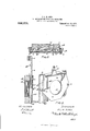
- Figure 1 is a sectional view of the tank of a carbid gas generator showing the location of my improved faucet.
- Fig. 2 is a perspective view of my sludge faucet.
- Fig. 3 is a horizontal section.
- Fig. 4: is a vertical section.
- A is the main casting of my sludge faucet, which is provided with a suitable orifice A to receive the inner end of the outlet pipe or tubular spout of the faucet.
- A is an annular rib surrounding the orifice at the inside and preferably provided with a smooth or ground face.
- A are guiding ribs formed in the casting A at each side and provided with intermediate bosses A*.
- A are stops formed at the bottom of the rib A and designed ,to limit the downward movement of the gate B.
- C is a plate of spring metal having a central openlng C corresponding in size to the opening A in the casting A, and held by screws D at each side as indicated, thereby exerting an inward pressure on the ribs B of the gate B.
- the faucet gate is an operating rod having a threaded lower end, which fits into a correspondingly threaded hole in the boss B
- the upper end of the rod E is connected to a lever F, which is pivoted on the bracket G secured to the top of the tank.
- the faucet gate By manipulating the lever F the faucet gate may be raised and lowered.
- all pressure of the spring plate C is removed therefrom and it lies free and the clear water, which is finally drawn out from the tank after the sludge has been removed will serve to keep the faces of the annular ribs B and A clear and clean.
- a sludge faucet for carbid gas generators comprising a casting having a central orifice and an annular rib surrounding the same CIT having a ground inner surface, bf a gate having an annular faced rib corresponding in diameter and having a ground outer surface, ribs extending 'ertically on the back of said gate, a fiat plate of spring metal provided With a central orifice and screws located one at each end for holding the plate eeaeas against the ribs on the gate, and clispesed centrally of the height of the plate as and for the purpose specified FREDERICK LINDLEY HUNT SIMS;
Landscapes
- Engineering & Computer Science (AREA)
- General Engineering & Computer Science (AREA)
- Mechanical Engineering (AREA)
- Sliding Valves (AREA)
Description
F. L. H. SIMS. SLUDGE FAUOET FOR OARBID GAS GENERATORS. .APPLIOATION FILED JULY 17, 1908.
936,375. Patented Oct. 12,1909.
2 SHEETS-SHEET 1.
fizz KM FL H 0 M i I F. L, H. SIMS. SLUDGE PAUGET FOR GARBID GAS GENERATORS.
APPLICATION FILED JULY 17, 1908.
Patented Oct. 12, 1909.
2 SHEETS-SHEET 2.
f vz/v 70/? FL. H S/MS.
r n I It v M7W55s AYNDREW. l v GRAHAH co. PKOYO-LTTHDGRAPHERS. wnsnmm'on. u A
UNITED STATES PATENT @FFIQ.
FREDERICK LINDLEY HUNT SIMS, OF TORONTO, ONTARIO, CANADA.
SLUDGE-FAUOET FOR CARBID-GAS GENERATORS.
To all whom it may concern:
Be it known that I, FREDERICK LINDLEY HUNT SIMS, of the city of Toronto, in the county of York, in the Province of Ontario, Canada, have invented certain new and useful Improvements in Sludge-Faucets Particularly Adapted for carbid-Gas Generators, of which the following is the specification.
My invention relates to improvements in sludge faucets particularly adapted for carbid gas generators, and the object of the invention is to devise a faucet, which will obviate any difficulty from leaking due to wear and from freezing, which are incident to faucets in which the slide or gate is used on the outside of the faucet.
A further object is to insure the valve seats always being kept clean.
My invention consists of a flanged casting, which is suitably secured in an orifice in the tank and is provided with a threaded orifice adapted to receive the outlet pipe or tubular spout of the faucet, and an inner ground projecting annular rib having a flat face, a closing gate having an operating stem connected thereto and a corresponding co-acting annular fiat face and a spring plate adapted to hold the closing gate on its seat when closed, the parts being arranged and constructed in detail as hereinafter more particularly explained.
Figure 1, is a sectional view of the tank of a carbid gas generator showing the location of my improved faucet. Fig. 2, is a perspective view of my sludge faucet. Fig. 3, is a horizontal section. Fig. 4:, is a vertical section.
In the drawings like letters of reference indicate corresponding parts in each figure.
A is the main casting of my sludge faucet, which is provided with a suitable orifice A to receive the inner end of the outlet pipe or tubular spout of the faucet.
A is an annular rib surrounding the orifice at the inside and preferably provided with a smooth or ground face.
A are guiding ribs formed in the casting A at each side and provided with intermediate bosses A*.
B is a gate provided at the top with an off-set boss B and on its front face with an annular rib B-, which is ground so that when the gate is in its normal position the annular rib B will lie against the rib A Specification of Letters Patent.
Application filed July 1'7, 1908.
Patented Oct. 12, 1909.
Serial No. 444,099.
A are stops formed at the bottom of the rib A and designed ,to limit the downward movement of the gate B.
B are ribs formed on the rear face of the gate B.
C is a plate of spring metal having a central openlng C corresponding in size to the opening A in the casting A, and held by screws D at each side as indicated, thereby exerting an inward pressure on the ribs B of the gate B.
E is an operating rod having a threaded lower end, which fits into a correspondingly threaded hole in the boss B The upper end of the rod E is connected to a lever F, which is pivoted on the bracket G secured to the top of the tank. By manipulating the lever F the faucet gate may be raised and lowered. When being raised as soon as the gate B reaches the position shown in Fig. 4, all pressure of the spring plate C is removed therefrom and it lies free and the clear water, which is finally drawn out from the tank after the sludge has been removed will serve to keep the faces of the annular ribs B and A clear and clean. As soon as the lever F is manipulated so as to force down the gate B such gate will upon its passing the pin D be pressed upon by the plate C and more and more so until it reaches the stop A when the maximum pressure of the spring plate C will be exerted upon the ribs B and thereby the faces B and A brought to abuteach other so closely indeed that absolutely no liability of any leakage of my sludge faucet is liable.
Heretofore where the closure for the spout was at the outside, the sludge and water entering into the spout or pipe would freeze therein, and consequently the faucet became useless. In my invention, however, it will be seen that as the gate B is located to the i11- side of the tubular spout or outlet pipe and on the outside of the machine in the water of the generator all liability of freezing is avoided and operation of the faucet at all times is easy. In my invention also there is no liability of the sludge drying upon the faucets as in the old forms of faucets as they are not subject to the action of the air, butare always located in the water.
lVhat I claim as my invention is:
A sludge faucet for carbid gas generators comprising a casting having a central orifice and an annular rib surrounding the same CIT having a ground inner surface, bf a gate having an annular faced rib corresponding in diameter and having a ground outer surface, ribs extending 'ertically on the back of said gate, a fiat plate of spring metal provided With a central orifice and screws located one at each end for holding the plate eeaeas against the ribs on the gate, and clispesed centrally of the height of the plate as and for the purpose specified FREDERICK LINDLEY HUNT SIMS;
Witnesses B. BOYD, A. THOMAS.
Priority Applications (1)
| Application Number | Priority Date | Filing Date | Title |
|---|---|---|---|
| US44409908A US936375A (en) | 1908-07-17 | 1908-07-17 | Sludge-faucet for carbid-gas generators. |
Applications Claiming Priority (1)
| Application Number | Priority Date | Filing Date | Title |
|---|---|---|---|
| US44409908A US936375A (en) | 1908-07-17 | 1908-07-17 | Sludge-faucet for carbid-gas generators. |
Publications (1)
| Publication Number | Publication Date |
|---|---|
| US936375A true US936375A (en) | 1909-10-12 |
Family
ID=3004797
Family Applications (1)
| Application Number | Title | Priority Date | Filing Date |
|---|---|---|---|
| US44409908A Expired - Lifetime US936375A (en) | 1908-07-17 | 1908-07-17 | Sludge-faucet for carbid-gas generators. |
Country Status (1)
| Country | Link |
|---|---|
| US (1) | US936375A (en) |
-
1908
- 1908-07-17 US US44409908A patent/US936375A/en not_active Expired - Lifetime
Similar Documents
| Publication | Publication Date | Title |
|---|---|---|
| US695147A (en) | Hydrant. | |
| US934188A (en) | Drain-valve. | |
| US1104292A (en) | Silent flushing apparatus. | |
| US1301188A (en) | Flushing device for water-closets. | |
| US439818A (en) | Valve for wash-basins | |
| US174181A (en) | Improvement in hydrants | |
| US533021A (en) | Flushing-valve for urinals | |
| US448096A (en) | Hydrant | |
| US1015653A (en) | Flushing system for closets. | |
| US756624A (en) | Shut-off valve. | |
| US263251A (en) | Water-closet valve | |
| US341424A (en) | Edmund ltjnkenheimer | |
| US569345A (en) | Albert p | |
| US1244195A (en) | Valve mechanism. | |
| US55893A (en) | Improvement in hydrants | |
| US997885A (en) | Steam-trap. | |
| US692024A (en) | Self-closing faucet. | |
| US525948A (en) | Faucet | |
| US408091A (en) | Self-closing hydrant | |
| US1244976A (en) | Compression stop and water cock. | |
| US189782A (en) | Improvement in water-closets | |
| US913808A (en) | Flush-tank supply-valve. | |
| US1085004A (en) | Valve. | |
| US1137578A (en) | Flushing apparatus. | |
| US1102469A (en) | Flushing-valve. |