US936013A - Gas-main. - Google Patents
Gas-main. Download PDFInfo
- Publication number
- US936013A US936013A US38068307A US1907380683A US936013A US 936013 A US936013 A US 936013A US 38068307 A US38068307 A US 38068307A US 1907380683 A US1907380683 A US 1907380683A US 936013 A US936013 A US 936013A
- Authority
- US
- United States
- Prior art keywords
- main
- gas
- openings
- pipe
- section
- Prior art date
- Legal status (The legal status is an assumption and is not a legal conclusion. Google has not performed a legal analysis and makes no representation as to the accuracy of the status listed.)
- Expired - Lifetime
Links
- 239000000571 coke Substances 0.000 description 4
- 238000010276 construction Methods 0.000 description 3
- 238000004140 cleaning Methods 0.000 description 2
- 238000004519 manufacturing process Methods 0.000 description 2
- 229910001018 Cast iron Inorganic materials 0.000 description 1
- CWYNVVGOOAEACU-UHFFFAOYSA-N Fe2+ Chemical compound [Fe+2] CWYNVVGOOAEACU-UHFFFAOYSA-N 0.000 description 1
- 229910000831 Steel Inorganic materials 0.000 description 1
- 229910000754 Wrought iron Inorganic materials 0.000 description 1
- 238000002485 combustion reaction Methods 0.000 description 1
- 230000004048 modification Effects 0.000 description 1
- 238000012986 modification Methods 0.000 description 1
- 239000010959 steel Substances 0.000 description 1
- 238000006467 substitution reaction Methods 0.000 description 1
Images
Classifications
-
- F—MECHANICAL ENGINEERING; LIGHTING; HEATING; WEAPONS; BLASTING
- F16—ENGINEERING ELEMENTS AND UNITS; GENERAL MEASURES FOR PRODUCING AND MAINTAINING EFFECTIVE FUNCTIONING OF MACHINES OR INSTALLATIONS; THERMAL INSULATION IN GENERAL
- F16L—PIPES; JOINTS OR FITTINGS FOR PIPES; SUPPORTS FOR PIPES, CABLES OR PROTECTIVE TUBING; MEANS FOR THERMAL INSULATION IN GENERAL
- F16L45/00—Pipe units with cleaning aperture and closure therefor
Definitions
- Our invention relates in general to the construction of gas mains and more especially to such as are used in distributing gas to coke ovens.
- the object of the invention is to provide a main of the above described class of substantially rectangular form in cross section and of considerable depth as compared with the width.
- the purpose of this construction is to allow deposits which form in such pipes to accumulate in the lower portion thereof, still leaving suliicient area above to carry the gas supply.
- a number of holes are arranged on one side of the pipe near the bottom, which are opened at intervals for the withdrawal of the accumulated deposits. These holes have cover-plates which are secured by means of a flat bar hinged at one end by a bolt, and having a notched or slotted opening at the other end to pass o-ver the corresponding bolt, the central portion of the bar pressing upon a rounded boss at the center of the cover.
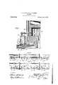
- ligurcsz- Figure 1 is a transverse sectional view of the gas main on a line of the center of one of the holes in the sides, showing also the burner and connection and a portion of a coke oven in section.
- Fig. 2 is a top plan view of the gas main with a portion broken away to show more clearly the construction of the hole in the side and the cover-plate.
- Fig. 3 is a front elevation of a portion of our improved gas main.
- the gas main 1 is composed of lengths of piping, having holes Q arranged on one side of the pipe near the bottom. These holes are closed by means of covers 3 each having two lugs or brackets 4 on their interior which rest upon the surface of the boundary of the hole itself, in order to maintain the cover in position and keep it from slipping down, as will be readily seen by referring to Fig. 1.
- a flat bar S is hinged at one end to -the bolt 6 and the other end of said bar is notched or slotted to catch under the head of the bolt 7, the central portion of the bar passes over a boss 9 on the outside central portion of the hole cover, so that when the nuts on bolts 6 and 7 are screwed up tight, the cover is securely held in position.
- the cover is provided with a handle 10. In the top of the main is a threaded opening 11 into which the connection 12 for the gas burner 13 which passes into the combustion chamber 14 of the coke oven 15, is screwed.
- Our improved gas main ismade up of sections which have outwardly extending flanges at both ends, which are bolted together in the usual manner.
- the mains are supported on lugs 17 and 18 which act with set screws 16 to restrain the expansion of the oven wall, which device however, is part of the oven and is not included in the present application.
- a pipe vsect-ion rectangular in cross section the depth being greater than the width thereof, said section being provided with openings in the sides, the lower edges of which are substantially coincident with the inn'er surface of the base of the pipe, a supporting lug, and external removable mechanical means for closing said openings.
- a pipe section provided with openings in the sides 'below the central portion thereof, the lower edge of the openings being substantially coincident with the inner surface of the base of the pipe, a supporting lug, projections on the outer surface of t-he pipe ad jacent to 'the openings, and covers secured by bars revolubly mounted on the said projections.
- a pipe or main provided with openingsyin the sides thereof, the lower edge of which is substantially coincident with the inner surface of the base vof the main, ⁇ covers for the openings provided with bosses which This is a feature of greatl section, and a supporting are spherical segments on their central portion, pivoted ⁇ bars engaging 'said bosses and means for securing the bars at their free ends.
Landscapes
- Engineering & Computer Science (AREA)
- General Engineering & Computer Science (AREA)
- Mechanical Engineering (AREA)
- Supports For Pipes And Cables (AREA)
Description
M. G. MOORE 6a R. C. GLAZIER.
' GAS MAIN.
APPLICATION FILED JUNE 25, 1907.
936,01 3. l Patented oct. 5, 1909.
RNEY.
l UNITED STATES PATENT OFFICE.
MARSHALL G. MOORE AND RALPH C. GLAZIER, 0F JOI-INSTOWN, PENNSYLVANIA.
GAS-MAIN.
Specicaton of Letters Patent.
Patented Oct. 5, 1909.
Application filed June 25, 1907. Serial No. 380,683.
To all whom it may concern.'
Be it known that we, MARSHALL Gr. Moonn and RALPH C. GLAZIER, citizens of the United States, residing in the city of Johnstown, county of Cambria, and State of Pennsylvania, have invented certain new and useful Improvements in Gas-Mains; and we do hereby declare the following to be a full, clear, and exact descrip-tion of the invention, such as will enable others skilled in the art to which it appertains to make and use the same.
Our invention relates in general to the construction of gas mains and more especially to such as are used in distributing gas to coke ovens.
The object of the invention is to provide a main of the above described class of substantially rectangular form in cross section and of considerable depth as compared with the width. The purpose of this construction is to allow deposits which form in such pipes to accumulate in the lower portion thereof, still leaving suliicient area above to carry the gas supply. A number of holes are arranged on one side of the pipe near the bottom, which are opened at intervals for the withdrawal of the accumulated deposits. These holes have cover-plates which are secured by means of a flat bar hinged at one end by a bolt, and having a notched or slotted opening at the other end to pass o-ver the corresponding bolt, the central portion of the bar pressing upon a rounded boss at the center of the cover.
The ordinary round mains of small diameter soon become filled with a deposit .which cannot be steamed or washed out, but must be scraped out with diiliculty, on account of their length and inaccessibility, whereas with our improved main the cleaning doors can be easily taken off and the deposits removed with but very little trouble or delay, and the gas need not therefore, be shut off from the coke ovens, but for a comparatively short time. VVhen the bottom of the main has been lilled with deposit, even to the extent of one-third of its capacity, or more, the pipe will supply all the gas required for use at the burners. This main may be made of cast iron, which is more durable than one of wrought iron or steel.
Referring to the accompanying drawings, forming a part of this specification in which similar letters of refe-rence indicate corresponding parts in all the ligurcsz-Figure 1 is a transverse sectional view of the gas main on a line of the center of one of the holes in the sides, showing also the burner and connection and a portion of a coke oven in section. Fig. 2 is a top plan view of the gas main with a portion broken away to show more clearly the construction of the hole in the side and the cover-plate. Fig. 3 is a front elevation of a portion of our improved gas main.
1n Ithe drawings the gas main 1 is composed of lengths of piping, having holes Q arranged on one side of the pipe near the bottom. These holes are closed by means of covers 3 each having two lugs or brackets 4 on their interior which rest upon the surface of the boundary of the hole itself, in order to maintain the cover in position and keep it from slipping down, as will be readily seen by referring to Fig. 1.
On each side of the holes and cast integral with the gas main are stud projections into which stud- bolts 6 and 7 are secured. A flat bar S is hinged at one end to -the bolt 6 and the other end of said bar is notched or slotted to catch under the head of the bolt 7, the central portion of the bar passes over a boss 9 on the outside central portion of the hole cover, so that when the nuts on bolts 6 and 7 are screwed up tight, the cover is securely held in position. The cover is provided with a handle 10. In the top of the main is a threaded opening 11 into which the connection 12 for the gas burner 13 which passes into the combustion chamber 14 of the coke oven 15, is screwed.
Our improved gas main ismade up of sections which have outwardly extending flanges at both ends, which are bolted together in the usual manner. The mains are supported on lugs 17 and 18 which act with set screws 16 to restrain the expansion of the oven wall, which device however, is part of the oven and is not included in the present application.
In order to remove one of the covers it is only necessary to unscrew the nuton the stud-bolt 7 when the flat bar S can be thrown back, thus releasing the cover, which can be lifted away by means of the handle 10, and the deposit removed in a very short time. The cover can then be replaced, the bar thrown back in its former position and the nut on stud-bolt 7 tightened. It will be observed that the lower edge of the opening is substantially coincident with the base of the main, thus facilitating the operation of cleaning. importance.
Although we have shown and described our improved gas main in considerable de.-
tail, 'we do not wish to be limited to the.
exact and specific details set forth, but may use suoli substitutions, modifications or equivalent thereof, as are embraced within the scope of our invention, as pointed out in th'e claims.
Having thus described our invention, what we claim and desire to secure by Letters Patent is:
l. As an article of manufacture, a pipe vsect-ion rectangular in cross section, the depth being greater than the width thereof, said section being provided with openings in the sides, the lower edges of which are substantially coincident with the inn'er surface of the base of the pipe, a supporting lug, and external removable mechanical means for closing said openings.
2. As an article of manufacture, a pipe section provided with openings in the sides 'below the central portion thereof, the lower edge of the openings being substantially coincident with the inner surface of the base of the pipe, a supporting lug, projections on the outer surface of t-he pipe ad jacent to 'the openings, and covers secured by bars revolubly mounted on the said projections.
3. A pipe or main provided with openingsyin the sides thereof, the lower edge of which is substantially coincident with the inner surface of the base vof the main, `covers for the openings provided with bosses which This is a feature of greatl section, and a supporting are spherical segments on their central portion, pivoted `bars engaging 'said bosses and means for securing the bars at their free ends.
4. A pipe section rectangular in cross section, the depth being greater than "the width thereof, said section being provided with openings in the sides, the lower edge of the openings being substantially coincident with the base of the main, the height of said openings not exceeding one half the height 'of the main, iianges at the ends of said pipe section, covers for said openings, each provided with a spherical boss on its central portion, 'handles 'on the covers, projections formed on the outer surface of the pipesections on the sides of each opening, and a bar bolted to one of said projections, the opposite end of the bar being provided with a slot to engage ythe bolt on the projection at the opposite side of the opening, said bar- -engaging the boss on the cover.
A pipe section rectangular in cross section, the vdepth being greater than the width thereof, said section being provided with openings in the sides, the lower edges of which openings are substantially coincident with 'the base of the Vmain,rcovers for the openings, flanges at the jends of the pipe lug secured to the base or platform.
In testimony whereof we hereto afliX our signatures in the presence of two witnesses.
MARSHALL G. MOORE.
4 RALH C. 'GLAZIER Vitnesses';
WVM. E. CARN'EY, ELM'ER 'SEAVEZ
Priority Applications (1)
| Application Number | Priority Date | Filing Date | Title |
|---|---|---|---|
| US38068307A US936013A (en) | 1907-06-25 | 1907-06-25 | Gas-main. |
Applications Claiming Priority (1)
| Application Number | Priority Date | Filing Date | Title |
|---|---|---|---|
| US38068307A US936013A (en) | 1907-06-25 | 1907-06-25 | Gas-main. |
Publications (1)
| Publication Number | Publication Date |
|---|---|
| US936013A true US936013A (en) | 1909-10-05 |
Family
ID=3004435
Family Applications (1)
| Application Number | Title | Priority Date | Filing Date |
|---|---|---|---|
| US38068307A Expired - Lifetime US936013A (en) | 1907-06-25 | 1907-06-25 | Gas-main. |
Country Status (1)
| Country | Link |
|---|---|
| US (1) | US936013A (en) |
-
1907
- 1907-06-25 US US38068307A patent/US936013A/en not_active Expired - Lifetime
Similar Documents
| Publication | Publication Date | Title |
|---|---|---|
| US559731A (en) | Hopper for charging coal | |
| US979841A (en) | Toggle-bolt. | |
| US590584A (en) | Range-boiler | |
| US190868A (en) | Improvement in cut-offs for gas and water pipes | |
| US808523A (en) | Grate. | |
| US993381A (en) | Pipe-damper. | |
| US468157A (en) | shapley | |
| US1257209A (en) | Evaporating-tank. | |
| US1193950A (en) | Autoine emile vezina | |
| US396020A (en) | Half to foster | |
| US380910A (en) | Patkick mogeb | |
| US418816A (en) | Sewer-trap | |
| US1048197A (en) | Smoke-pipe connection and check-damper for heaters. | |
| US235263A (en) | Stove-pipe damper | |
| US969655A (en) | Nut-lock. | |
| US544410A (en) | Philip j | |
| US1069826A (en) | Stovepipe-cleaner. | |
| US815160A (en) | Grate. | |
| US1030476A (en) | Car-bolt appliance. | |
| US759203A (en) | Automatic sprinkler for ash-pans. | |
| US1094702A (en) | Furnace-front. | |
| US936536A (en) | Service-box. | |
| US499720A (en) | Joseph darby | |
| US810479A (en) | Railway. | |
| US1737669A (en) | Rail joint |