US9329680B2 - Terminal and method for iris scanning and proximity sensing - Google Patents
Terminal and method for iris scanning and proximity sensing Download PDFInfo
- Publication number
- US9329680B2 US9329680B2 US13/887,670 US201313887670A US9329680B2 US 9329680 B2 US9329680 B2 US 9329680B2 US 201313887670 A US201313887670 A US 201313887670A US 9329680 B2 US9329680 B2 US 9329680B2
- Authority
- US
- United States
- Prior art keywords
- light
- iris
- level
- terminal
- amount
- Prior art date
- Legal status (The legal status is an assumption and is not a legal conclusion. Google has not performed a legal analysis and makes no representation as to the accuracy of the status listed.)
- Active, expires
Links
- 238000000034 method Methods 0.000 title claims abstract description 34
- 238000004458 analytical method Methods 0.000 claims description 35
- 210000000554 iris Anatomy 0.000 description 148
- 230000006870 function Effects 0.000 description 10
- 238000005516 engineering process Methods 0.000 description 7
- 238000005286 illumination Methods 0.000 description 6
- 230000009471 action Effects 0.000 description 4
- 238000012545 processing Methods 0.000 description 4
- 230000008901 benefit Effects 0.000 description 3
- 238000004891 communication Methods 0.000 description 3
- XUMBMVFBXHLACL-UHFFFAOYSA-N Melanin Chemical compound O=C1C(=O)C(C2=CNC3=C(C(C(=O)C4=C32)=O)C)=C2C4=CNC2=C1C XUMBMVFBXHLACL-UHFFFAOYSA-N 0.000 description 2
- 238000013459 approach Methods 0.000 description 2
- 238000010586 diagram Methods 0.000 description 2
- 230000008569 process Effects 0.000 description 2
- 210000001525 retina Anatomy 0.000 description 2
- 230000000007 visual effect Effects 0.000 description 2
- 241000895680 Stylosanthes guianensis Species 0.000 description 1
- 230000001276 controlling effect Effects 0.000 description 1
- 230000004313 glare Effects 0.000 description 1
- 238000012986 modification Methods 0.000 description 1
- 230000004048 modification Effects 0.000 description 1
- 230000003287 optical effect Effects 0.000 description 1
- 239000000049 pigment Substances 0.000 description 1
- 238000003672 processing method Methods 0.000 description 1
- 230000001105 regulatory effect Effects 0.000 description 1
Images


Classifications
-
- G—PHYSICS
- G06—COMPUTING; CALCULATING OR COUNTING
- G06V—IMAGE OR VIDEO RECOGNITION OR UNDERSTANDING
- G06V10/00—Arrangements for image or video recognition or understanding
- G06V10/40—Extraction of image or video features
-
- G—PHYSICS
- G06—COMPUTING; CALCULATING OR COUNTING
- G06F—ELECTRIC DIGITAL DATA PROCESSING
- G06F3/00—Input arrangements for transferring data to be processed into a form capable of being handled by the computer; Output arrangements for transferring data from processing unit to output unit, e.g. interface arrangements
- G06F3/01—Input arrangements or combined input and output arrangements for interaction between user and computer
- G06F3/011—Arrangements for interaction with the human body, e.g. for user immersion in virtual reality
- G06F3/013—Eye tracking input arrangements
-
- G06K9/00604—
-
- G06K9/2018—
-
- G—PHYSICS
- G06—COMPUTING; CALCULATING OR COUNTING
- G06V—IMAGE OR VIDEO RECOGNITION OR UNDERSTANDING
- G06V10/00—Arrangements for image or video recognition or understanding
- G06V10/10—Image acquisition
-
- G—PHYSICS
- G06—COMPUTING; CALCULATING OR COUNTING
- G06V—IMAGE OR VIDEO RECOGNITION OR UNDERSTANDING
- G06V10/00—Arrangements for image or video recognition or understanding
- G06V10/10—Image acquisition
- G06V10/12—Details of acquisition arrangements; Constructional details thereof
- G06V10/14—Optical characteristics of the device performing the acquisition or on the illumination arrangements
- G06V10/143—Sensing or illuminating at different wavelengths
-
- G—PHYSICS
- G06—COMPUTING; CALCULATING OR COUNTING
- G06V—IMAGE OR VIDEO RECOGNITION OR UNDERSTANDING
- G06V40/00—Recognition of biometric, human-related or animal-related patterns in image or video data
- G06V40/10—Human or animal bodies, e.g. vehicle occupants or pedestrians; Body parts, e.g. hands
- G06V40/18—Eye characteristics, e.g. of the iris
- G06V40/19—Sensors therefor
Definitions
- the present invention relates to a terminal and method for iris scanning and proximity sensing, and more particularly, to a terminal capable of increasing the iris scanning rate by sharing light emitting illumination needed for proximity sensing and light emitting illumination needed for iris scanning, and a method of iris scanning and proximity sensing.
- Iris scanning is used to collect information of characteristics of respective attributes of irises of people and use the information in authentication technology for security.
- the iris has unique patterns whose number is larger than that of the fingerprint.
- iris scanning is a non-contact type of scanning and authentication, and thus people do not feel uncomfortable with the iris scanning.
- a person may be accurately identified even if the person wears eyeglasses or contact lenses.
- iris scanning usually takes less than two seconds, and thus iris scanning is being evaluated as a biometric identification technology more advanced than a fingerprint or retina scanning technology.
- a terminal such as a portable terminal, a mobile device, a cell phone, or other electronic devices
- the amount of information stored in the terminal increases, the importance of information is on the increase, and a security technology applied to the terminal is also getting sophisticated.
- iris scanning is a technology more advanced than a fingerprint or retina scanning technology in terms of the accuracy and speed, and scanning without contact is possible using a camera.
- the security of the terminal may be more strengthened, and the terminal may provide various services related with authentication to user.
- iris scanning is not being widely applied to terminals in Korea and elsewhere. This is partly because of the costs of iris scanning technology in the prior art, but is also because of the scanning rate problem.
- a terminal uses a flash built in for photographing as illumination for iris scanning.
- iris scanning is possible only using a general flash as illumination.
- other people including Asian people, many Asians do not have sufficient melanin pigments in their eyes, and thus infrared rays need to be stably secured.
- an illuminator of infrared rays needs to be separately installed to increase the iris scanning rate.
- having a separate built-in infrared ray illumination for iris scanning would make it difficult for the terminal to be lighter and smaller.
- the present invention has been made in view of the above problems, and an object of the present invention is to provide an apparatus and method for increasing the iris scanning rate using a proximity sensor built into a terminal without installing a separate infrared ray illuminator in the terminal.
- Another object of the present invention is to provide a terminal and method which provides an illuminator needed for iris sensing, and, at the same time, allows proximity sensing.
- a method of iris scanning and proximity sensing includes: an operation of receiving selection information of an operation mode; an iris sensing operation of emitting light having an amount of light of a first level, and photographing an iris using the emitted light if a selected operation mode is a iris scanning mode; a proximity sensing operation of emitting light having an amount of light of a second level, and sensing information on whether an object has approached using the emitted light if the selected operation mode is a proximity sensing mode; a control operation of recognizing the iris using the photographed iris image, and performing a function according to the sensed information on whether the object has approached, wherein the first level has a value higher than the value of the second level.
- a terminal for iris scanning and proximity sensing includes: an input unit for receiving selection information of an operation mode; an iris sensing unit for emitting light having an amount of light of a first level, and photographing an iris using the emitted light if a selected operation mode is a iris scanning mode; a proximity sensing unit for emitting light having an amount of light of a second level, and sensing information on whether an object has approached using the emitted light if the selected operation mode is a proximity sensing mode; a controller for recognizing the iris using the photographed iris image, and performing a function according to the sensed information on whether the object has approached, wherein the first level has a value higher than the value of the second level.
- FIG. 1A schematically illustrates a configuration of a terminal according to an exemplary embodiment of the present invention
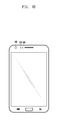
- FIG. 1B illustrates an external appearance of the terminal according to the exemplary embodiment of the present invention
- FIG. 2 is a block diagram illustrating a configuration of the terminal according to the exemplary embodiment of the present invention
- FIG. 3 illustrates power supplied to a light emitting unit of the terminal in an iris scanning mode according to the exemplary embodiment of the present invention
- FIG. 4 illustrates power supplied to the light emitting unit of the terminal in a proximity sensing mode according to the exemplary embodiment of the present invention
- FIG. 5 illustrates the power of light collected in a light receiving unit of the terminal in the iris scanning mode according to the exemplary embodiment of the present invention
- FIG. 6 illustrates the power of light collected in the light receiving unit of the terminal in the proximity sensing mode according to the exemplary embodiment of the present invention
- FIG. 7 is a flowchart illustrating a method of iris scanning and proximity sensing according to the exemplary embodiment of the present invention.
- FIG. 8 is a flowchart illustrating in detail the method of iris scanning and proximity sensing in the iris scanning mode according to the exemplary embodiment of the present invention.
- FIG. 9 is a flowchart illustrating in detail the method of iris scanning and proximity sensing in the iris scanning mode according to an alternative exemplary embodiment of the present invention.
- FIG. 10 is a flowchart illustrating in detail a method of proximity sensing in the proximity sensing mode according to the exemplary embodiment of the present invention.
- a terminal refers to any kind of device capable of processing data which is transmitted or received to or from any external entity.
- the terminal may display icons or menus on a screen to which stored data and various executable functions are assigned or mapped.
- the terminal may include a computer, a notebook, a tablet PC, a mobile device, and the like.
- a screen refers to a display or other output devices which visually display information to the user, and which optionally are capable of receiving and electronically processing tactile inputs from a user using a stylo, a finger of the user, or other techniques for conveying a user selection from the user to the output devices.
- FIG. 1A schematically illustrates a configuration of a terminal according to an exemplary embodiment of the present invention
- FIG. 1B illustrates an external appearance of the terminal according to the exemplary embodiment of the present invention.
- the terminal may include a camera 10 , a light emitting unit 30 , a light receiving unit 50 , and a power supply unit 70 .
- the external appearance of the terminal is similar to the terminal including a proximity sensor and a camera according to the prior art, but the present invention further includes the power supply unit 70 for iris scanning.
- the light emitting unit 30 is positioned between the camera 10 and the light receiving unit 50 , but the present invention is not limited to this example.
- FIG. 2 is a block diagram illustrating a configuration of the terminal for iris scanning and proximity sensing according to the exemplary embodiment of the present invention.
- the terminal for iris scanning and proximity sensing may include an input unit 110 for receiving an input of selection information of the operation mode from a user, a controller 130 for controlling iris sensing and proximity sensing, a proximity sensing unit 100 for sensing whether an object has approached, and an iris sensing unit 200 for photographing an iris, and may further include a display unit 180 for displaying feedback information and a storage unit 190 for storing information needed for iris scanning, and data needed for iris scanning and proximity sensing.
- the proximity sensing unit 100 may include a power supply unit 140 , a light emitting unit 150 and a light receiving unit 160
- the iris sensing unit 200 according to the exemplary embodiment of the present invention may also include the power supply unit 140 and the light emitting unit 150 as well as a camera 170 .
- the proximity sensing unit 100 and the iris sensing unit 200 according to the exemplary embodiment of the present invention share one or more modules, such as the power supply unit 140 and the light emitting unit 150 , but perform different functions.
- the proximity sensing unit 100 and the iris sensing unit 200 may be separately operated according to the selection information, and may be simultaneously operated according to a need and/or a selection for simultaneous operations.
- the input unit 110 receives selection information of the operation mode.
- the iris scanning mode and the proximity sensing mode may be included in the operation mode, and the proximity sensing mode may be set as a default value.
- the proximity sensing mode is set as the default mode because the proximity sensing mode is used in general operations of the terminal, and the amount of light required for the proximity sensing is less than the amount of light required for iris scanning.
- the input unit 110 may be a soft button, a virtual button, and/or an icon of a touch pad or touch screen, a keyboard, a microphone, or a sensor for sensing an action or a gesture.
- the terminal may further include a module for analyzing the selection information inputted by a voice, an action or a gesture, and transmitting the information to the controller 130 .
- the module used as the input unit 110 is not limited to the above described example, and the input of the selection information is also possible by a combination of any of the components in the exemplary embodiment of the present invention.
- the iris sensing unit 200 emits light having an amount of light of a first level, such as a first intensity level, and photographs the iris using the emitted light.
- the selection operation mode is a proximity sensing mode
- the proximity sensing unit 100 emits light having an amount of light of a second level, such as a second intensity level, and senses whether an object has approached using the emitted light.
- the controller 130 senses the iris using the photographed iris image, or performs a corresponding function according to whether the object has approached.
- the first level has a light amount value higher than the light amount value of the second level because the iris scanning requires an amount of light greater than the amount of light in the proximity sensing.
- the light having the amount of light of the first level emitted in the iris scanning mode and the light having the amount of light of the second level emitted in the proximity sensing mode may be emitted by one module. That is, the iris sensing unit 200 and the proximity sensing unit 100 may share the module for emitting light and/or may be implemented by a single component.
- each component included in the proximity sensing unit 100 and the iris scanning unit 200 is operated in each operation mode by the modules. It should be noted that the proximity sensing unit 100 and the iris sensing unit 200 may share some modules as explained above.
- the power supply unit 140 supplies power, corresponding to the amount of light of the first level, to the light emitting unit 150 for emitting light, and in the proximity sensing mode, the power supply unit 140 supplies power, corresponding to the amount of light of the second level, to the light emitting unit 150 for emitting light.
- the controller 130 may receive the information, determine the power to be supplied to the light emitting unit 150 in each mode, and transmit a power control signal to the power supply unit 140 . If the power control signal is received, the power supply unit 140 may supply power to the light emitting unit 150 according to the power control signal.
- the first level which is the amount of light emitted in the iris scanning mode
- the second level which is the amount of light emitted in the proximity sensing mode
- the first and second level values may be changed according to a control signal from the controller 130 to the light emitting unit 150 , with the control signal generated from a user selection received through the input unit 110 , or generated from light level values previously stored in the storage unit 190 .
- the light emitting unit 150 emits light using power supplied by the power supply unit 140 . That is, in the iris scanning mode, the light having the amount of the first level is emitted, while in the proximity sensing mode, the light having the amount of the second level is emitted.
- the light emitted by the light emitting unit 150 may be infrared rays, and the light emitting unit 150 may be a light emitting diode (LED) or an organic light emitting diode (OLED). Any device capable of emitting infrared rays may be used as the light emitting unit 150 , and the present invention is not limited to the above described exemplary embodiment.
- the light emitting unit 150 emits light having a relatively large amount of light in the iris scanning mode compared to the proximity sensing mode. For example, with light levels measured on a scale of 1 to 10, if the light emitting unit 150 emits light having the amount of light of level 1 in the proximity sensing mode, the light emitting unit 150 may emit light having the amount of light of level 10 in the iris scanning mode. Further, the light emitting unit 150 may be disposed between the camera 170 and the light receiving unit 160 , as shown in FIG. 1A for the corresponding camera 10 , the light emitting unit 30 , and the light receiving unit 50 .
- the proximity sensing unit 100 and/or the controller 130 may recognize and/or measure the distance between the terminal and the iris with a small error by allowing the emitted light to be radiated near the gazing iris, and the position of the terminal and/or the module implementing the light emitting units 30 , 150 may be physically regulated and orientated so that the emitted light is sufficiently directed on the iris.
- the camera 170 photographs an iris lighted up by the light emitted from the light emitting unit 150 .
- the camera 170 may transmit the photographed iris image to the controller 130 .
- the camera 170 may automatically photograph the iris from a certain distance.
- the camera 170 may be set to automatically photograph the user's iris when the difference between the distance recognized in the controller 130 and the optimal distance for iris scanning is within a preset range of allowable deviation from the optimal distance.
- the optimal distance may be a predetermined distance, and the optimal distance and the preset range may be stored in the storage unit 190 , or may be selected or set by the user using the input unit 110 .
- the controller 130 sets a light reception analysis level to correspond to the amount of light of the first level when operating in the iris scanning mode, and alternatively sets the light reception analysis level to correspond to the amount of light of the second level when operating in the proximity sensing mode.
- the light reception analysis level is a criterion value for determining whether an object has approached. That is, proximity sensing may be possible even in the iris scanning mode, and because the amount of light emitted in the iris scanning mode is different from the amount of light emitted in the proximity sensing mode, the light reception analysis level for analyzing the light, which reflects off an object and is collected, has different values in each mode.
- the light reception analysis level may be a predetermined value which is also stored in the storage unit 190 , or may be selected or set by the user using the input unit 110 .
- the controller 130 may transmit a power control signal to the power supply unit 140 so that the power supply unit 140 may supply power corresponding to the amount of light of each level in the iris scanning mode or proximity sensing mode. Further, the power control signal is transmitted to the power supply unit 140 , and at the same time, the light reception analysis level corresponding to the amount of light of each level may be set and may be transmitted to the light receiving unit 160 . In this case, the light reception analysis level corresponding to the amount of light corresponding to each level may have been stored in advance in the storage unit 190 . In an alternative embodiment, the controller 130 may collect light which reflects off of an outside object, analyze the collected light, and then set the light reception analysis level.
- the controller 130 may compare the recognized distance with the optimal distance for iris scanning, and transmit the feedback information according to the result of the comparison to the display unit 180 .
- the optimal distance for iris scanning may be information stored in advance in the storage unit 190 , or information received through a communication network, either through the input unit 110 or a communication interface of the controller 130 . If the emitted light reflects off an object, the light receiving unit 160 collects the reflected light, and recognizes the distance with the object using the collected light and the light reception analysis level.
- the light receiving unit 160 is an element of the proximity sensing unit 100 , and is used in sensing whether the object has approached the terminal.
- the light receiving unit 160 is a module used in the proximity sensing, but the light receiving unit 160 may also be used to search for an appropriate distance for iris scanning even in the iris scanning mode. As described above, the amount of light emitted in each mode is different, and thus the amount of reflected light is also different. Hence, in the iris scanning mode, the light receiving unit 160 receives the light reception analysis level corresponding to the amount of light of the first level from the controller 130 , and in the proximity sensing mode, the light receiving unit 160 receives the light reception analysis level corresponding to the amount of light of the second level from the controller 130 .
- the light reception analysis level is a criterion for determining whether an object has approached as described above.
- the light receiving unit 160 compares the power of the collected light with the light reception analysis level, and determines that an object has approached the terminal in case the collected light has a power higher than the light reception analysis level. Further, in case the collected light has a power lower than the light reception analysis level, the light receiving unit 160 may determine that the object has not approached the terminal 100 .
- the light receiving unit 160 collects light having an amount of light greater than that in the proximity sensing mode. However, in the proximity sensing mode, the controller 130 sets the light reception analysis level higher, and thus the light receiving unit 160 may recognize the distance with the object even if the amount of light collected in each mode is different.
- the amount of light is high, and thus the available distance for proximity sensing may be further increased.
- the relationship between the light emitted by the light emitting unit 150 and received the light receiving unit 160 and the light reception analysis level will be described in detail with reference to FIGS. 3 to 6 .
- the display unit 180 displays the feedback information according to the result of comparison between the distance recognized between an object, such as user's eye and face and the terminal, and the optimal distance for iris scanning.
- the feedback information may be guide information on whether the distance between the object and the terminal should be farther or closer as a result of the result of the comparison between the recognized distance and the optimal distance.
- the user may set the distance between the terminal and the user to be optimal using the displayed feedback information.
- the display unit 180 includes a display, which may be composed of at least one light emitting diode (LED) or any other known type of display device.
- the display unit 180 may be replaced by or supplemented by any other known type of output device, such as audio or tactile output devices such as a speaker, a vibration generation device, etc., and any mode capable of displaying or outputting certain information to user may be used as a display unit 180 or an output device including or instead of the display unit 180 .
- the user regulates the distance in the state where the user gazes at the camera 170 , and thus the appropriate distance may be outputted using the sense of touch and the sense of hearing.
- the controller 130 may analyze result data from such proximity and iris sensing, and perform a function in each mode of the proximity sensing mode and the iris sensing mode. That is, in the proximity sensing mode, if the proximity sensing unit 100 , including the power supply unit 140 , the light emitting unit 150 and the light receiving unit 160 , senses whether the object has approached, the controller 130 performs a function according to the sensed information on whether the object has approached.
- the controller 130 may deactivate the input unit 110 and the display unit 180 ; for example, a touch screen turns on when a face approaches towards the touch screen during a phone call, but turns off when the face moves away from the screen. If it is determined that the object has not approached the terminal according to the proximity sensing unit 100 , the controller 130 may activate the input unit 110 and the display unit 180 .
- the controller 130 may recognize the iris through a process of comparing the obtained iris image with an iris image stored in advance in the storage unit 190 .
- iris scanning is possible through the illumination used in the proximity sensing, and the infrared rays used in the proximity sensing are not visible unlike a general illuminator which uses visible light, and thus the user may gaze at the camera 170 without experiencing any glare. Further, if the proximity sensing is used in the iris scanning mode, the optimal distance for iris scanning may be found without checking a separate screen guide, and thus the camera 170 and the screen of the display unit 180 do not need to be separately checked by the user.
- FIG. 3 illustrates power supplied to the light emitting unit 150 of the terminal in the iris scanning mode
- FIG. 4 illustrates power supplied to the light emitting unit 150 of the terminal in the proximity sensing mode, respectively, according to the exemplary embodiment of the present invention
- FIG. 5 illustrates the power collected in the light receiving unit 160 of the terminal in the iris scanning mode
- FIG. 6 illustrates the power collected in the light receiving unit 160 in the proximity sensing mode, respectively, according to the exemplary embodiment of the present invention.
- the power supplied to the light emitting unit 150 in the iris scanning mode is higher than the power supplied to the light emitting mode 150 in the proximity sensing mode.
- the amount of light emitted in the iris scanning mode is higher than the amount of light emitted in the proximity sensing mode.
- the power of light collected in the light receiving unit 160 has a higher value in the iris scanning mode as shown in FIG. 5 .
- the power levels of the collected light may have a deviation depending on whether an object has approached, or the overall average value of the power levels of the collected light may be different in each mode.
- the size of the light reception analysis level, as a threshold level, which is the criterion for determining whether an object approached is set to be the same in both of the iris scanning and proximity sensing modes, it cannot be determined whether the object has approached.
- the controller 130 regulates the amount of light emitted according to the selection information corresponding to selecting either the iris scanning mode or the proximity sensing mode, and regulates the light reception analysis level according to the amount of emitted or collected light.
- the light receiving unit 160 may determine whether the object has approached in a manner that fits each of the iris scanning mode and the proximity sensing mode.
- FIGS. 7 to 9 a method of iris scanning and proximity sensing according to the exemplary embodiment of the present invention will be described with reference to FIGS. 7 to 9 .
- FIG. 7 is a flowchart illustrating the method of iris scanning and proximity sensing according to the exemplary embodiment of the present invention.
- the input unit 110 receives selection information of the operation mode in step 700 .
- the selection information for selecting the iris scanning mode or the proximity sensing mode may be inputted using a soft button of a touch pad or a keyboard, and may also be inputted by a voice, action or gesture, through the input unit 110 .
- the controller 130 determines whether the selected operation mode is the iris scanning mode or the proximity sensing mode in step 710 . If the selected operation mode is the iris scanning mode, the iris sensing unit 200 emits light having the amount of light of the first level in step 730 , and senses the iris 750 . Further, the iris is scanned in step 770 using the obtained iris image as a result of the sensing in step 750 . The method then ends.
- the proximity sensing unit 100 emits light having the amount of light of the second level in step 720 , and senses whether the object has approached in step 740 . Further, a corresponding function is performed according to the result of the proximity sensing in step 760 , and the method then ends.
- the first level has a value higher than the second level.
- the light having the amount of light of the first level and the light having the amount of light of the second level may be light emitted by one module having the light emitting unit 150 .
- the power supply unit 140 may supply power corresponding to the amount of light of the first level to the light emitting unit 150 which emits light in step 730 , and the iris lighted up by the light having the amount of light of the first level may be photographed in step 750 .
- FIG. 8 is a flowchart illustrating in detail the method of iris scanning and proximity sensing in the iris scanning mode according to the exemplary embodiment of the present invention, and as specified steps 730 and 750 of FIG. 7 .
- the power supply unit 140 supplies power, corresponding to the amount of light of the first level, to the light emitting unit 150 in step 800 .
- the controller 130 sets the light reception analysis level to correspond to the amount of light of the first level in step 820 .
- the light emitting unit 150 emits light having the amount of light of the first level with the power supplied from the power supply unit 140 in step 830 . If the emitted light reflects off an object, such as the user or the eye or iris of the user, the light receiving unit 160 collects the reflected light in step 840 . Next, the light receiving unit 160 recognizes the distance between the terminal and the object using the collected light and the light reception analysis level in step 850 .
- the controller 130 determines whether the difference between the recognized distance and the optimal distance is within the preset range in step 860 . As a result, if the difference between the recognized distance and the optimal distance is within the preset range, the camera 170 photographs the iris lighted up by the light having the amount of light of the first level in step 880 , and the method ends.
- the display unit 180 displays or otherwise outputs feedback information, such as a visual and/or audible message or an indication of the recognized and optimal distances, in step 870 , so that a user may adjust the distance, and the method loops back to step 830 to perform iris scanning mode with the iris at the new adjusted distance. If the user regulates the distance between the user's iris and the terminal according to the displayed feedback information, the light emitting unit 150 re-emits the light at step 830 so that the distance between user and the terminal may be recognized. Through such a process, the terminal may scan the iris from the distance which is most optimal for iris scanning.
- feedback information such as a visual and/or audible message or an indication of the recognized and optimal distances
- FIG. 9 illustrates the method of iris scanning and proximity sensing in the iris scanning mode according to the alternative exemplary embodiment of the present invention.
- the power supply unit 140 supplies power corresponding to the amount of light of the first level to the light emitting unit in step 900 .
- the controller 130 sets the light reception analysis level to correspond to the amount of light of the first level in step 920 .
- the light reception analysis level may be set at step 920 , but this operation may alternatively be performed any time before step 970 in which the light reception analysis level is used.
- the light emitting unit 150 emits light having the amount of light of the first level with the power supplied from the power supply unit 140 in step 930 .
- the camera 170 photographs the iris lighted up by the emitted light in step 940 .
- the photographing may be continually performed by the camera 170 and/or an iris scanning engine. After the iris is scanned, if the light reflects off the object, the light receiving unit 160 collects the reflected light in step 950 , and recognizes the distance of the terminal from the object using the collected light and the light reception analysis level in step 970 . In the exemplary embodiment illustrated in FIG. 9 , steps 940 and 950 are sequentially performed, but the steps 940 and 950 may alternatively be performed at the same time. After step 970 , the display unit 180 displays or otherwise outputs visual and/or audible feedback information of the recognized distance in step 990 , and the method ends.
- the terminal may provide simple feedback information on the recognized distance while simultaneously performing iris photographing and proximity sensing.
- the feedback information may include, for example, direction information on the distance between the object and the terminal, information on whether user should move closer or further, etc.
- the user may manually photograph the iris from the optimal distance using the feedback information.
- FIG. 10 is a flowchart illustrating in detail the method of proximity sensing in the proximity sensing mode according to the exemplary embodiment of the present invention, and as specified in steps 720 and 740 of FIG. 7 .
- the power supply unit 140 supplies power corresponding to the amount of light of the second level to the light emitting unit 150 in step 1000 .
- the controller 130 sets the light reception analysis level to correspond to the amount of light of the first level in step 1020 .
- the light emitting unit 150 emits light having the amount of light of the second level with the power supplied from the power supply unit 140 in step 1030 . If the emitted light reflects off the object, the light receiving unit 160 collects the reflected light in step 1040 . Next, the light receiving unit 160 and/or the controller 130 recognizes and/or measures the distance from the object using the collected light and the light reception analysis level in step 1050 .
- the controller 130 determines whether the terminal is adjacent to the object in step 1060 . As a result of the determination in step 1060 , if it is determined that the object has approached the terminal, the controller 130 may deactivate the input unit 110 and the display unit 180 in step 1070 , in order to reduce power consumption to provide more power for the iris scanning mode, and the method ends. However, as a result of the determination in step 1060 , if it is determined that the object has not approached the terminal, the terminal may activate the input unit 110 and the display unit 180 in step 1080 .
- the iris scanning rate may be increased using a proximity sensor built in a terminal without adding a separate infrared ray illuminator in the terminal.
- a terminal may provide an infrared ray or visible light illuminator needed for iris scanning, and, at the same time, may perform proximity sensing.
- the above-described apparatus and methods according to the present invention can be implemented in hardware or firmware, or as software or computer code, or combinations thereof.
- the software or computer code can also be stored in a non-transitory recording medium such as a CD ROM, a RAM, a ROM whether erasable or rewritable or not, a floppy disk, CDs, DVDs, memory chips, a hard disk, a magnetic storage media, an optical recording media, or a magneto-optical disk or computer code downloaded over a network originally stored on a remote recording medium, a computer readable recording medium, or a non-transitory machine readable medium and to be stored on a local recording medium, so that the methods described herein can be rendered in such software, computer code, software modules, software objects, instructions, applications, applets, apps, etc.
- the computer, the processor, microprocessor controller or the programmable hardware include volatile and/or non-volatile storage and memory components, e.g., RAM, ROM, Flash, etc. that may store or receive software or computer code that when accessed and executed by the computer, processor or hardware implement the processing methods described herein.
- volatile and/or non-volatile storage and memory components e.g., RAM, ROM, Flash, etc.
- the execution of the code transforms the general purpose computer into a special purpose computer for executing the processing shown herein.
- the program may be electronically transferred through any medium such as communication signals transmitted by wire/wireless connections, and their equivalents.
- the programs and computer readable recording medium can also be distributed in network-coupled computer systems so that the computer readable code is stored and executed in a distributed fashion.
Applications Claiming Priority (2)
| Application Number | Priority Date | Filing Date | Title |
|---|---|---|---|
| KR10-2012-0047311 | 2012-05-04 | ||
| KR1020120047311A KR102023611B1 (ko) | 2012-05-04 | 2012-05-04 | 홍채 인식 및 근접 센싱 가능한 단말 장치 및 방법 |
Publications (2)
| Publication Number | Publication Date |
|---|---|
| US20130293457A1 US20130293457A1 (en) | 2013-11-07 |
| US9329680B2 true US9329680B2 (en) | 2016-05-03 |
Family
ID=49512149
Family Applications (1)
| Application Number | Title | Priority Date | Filing Date |
|---|---|---|---|
| US13/887,670 Active 2034-07-09 US9329680B2 (en) | 2012-05-04 | 2013-05-06 | Terminal and method for iris scanning and proximity sensing |
Country Status (2)
| Country | Link |
|---|---|
| US (1) | US9329680B2 (ko) |
| KR (1) | KR102023611B1 (ko) |
Cited By (2)
| Publication number | Priority date | Publication date | Assignee | Title |
|---|---|---|---|---|
| US20160166204A1 (en) * | 2014-12-16 | 2016-06-16 | International Business Machines Corporation | Detecting visual impairment through normal use of a mobile device |
| US10616474B2 (en) | 2016-08-23 | 2020-04-07 | Samsung Electronics Co., Ltd. | Electronic device including iris recognition sensor and method of operating the same |
Families Citing this family (23)
| Publication number | Priority date | Publication date | Assignee | Title |
|---|---|---|---|---|
| KR102332320B1 (ko) * | 2014-02-21 | 2021-11-29 | 삼성전자주식회사 | 홍채 컬러 인식을 갖는 멀티-밴드 생체인식 카메라 |
| KR101608316B1 (ko) | 2014-05-08 | 2016-04-01 | 아이리텍 잉크 | 실외 및 실내에서의 홍채이미지 획득장치 및 방법 |
| US10262203B2 (en) * | 2014-09-02 | 2019-04-16 | Samsung Electronics Co., Ltd. | Method for recognizing iris and electronic device therefor |
| KR102226177B1 (ko) * | 2014-09-24 | 2021-03-10 | 삼성전자주식회사 | 사용자 인증 방법 및 그 전자 장치 |
| KR102266730B1 (ko) * | 2014-10-20 | 2021-06-21 | 삼성전자주식회사 | 전자 장치 |
| KR102376954B1 (ko) * | 2015-03-06 | 2022-03-21 | 삼성전자주식회사 | 홍채를 촬영하기 위한 광을 조사하는 방법 및 그 디바이스 |
| US20160275348A1 (en) * | 2015-03-17 | 2016-09-22 | Motorola Mobility Llc | Low-power iris authentication alignment |
| US20160282934A1 (en) * | 2015-03-25 | 2016-09-29 | Motorola Mobility Llc | Presence detection for gesture recognition and iris authentication |
| US20160350607A1 (en) * | 2015-05-26 | 2016-12-01 | Microsoft Technology Licensing, Llc | Biometric authentication device |
| KR101872757B1 (ko) * | 2016-04-18 | 2018-06-29 | (주)파트론 | 광학 센서 장치 및 광학 센싱 방법 |
| KR102553308B1 (ko) * | 2016-06-16 | 2023-07-11 | 삼성전자주식회사 | 이미지 검출 장치 및 이를 이용한 이미지 검출 방법 |
| US10547829B2 (en) * | 2016-06-16 | 2020-01-28 | Samsung Electronics Co., Ltd. | Image detecting device and image detecting method using the same |
| KR101898067B1 (ko) * | 2016-06-22 | 2018-09-12 | (주)파트론 | 광학 센서 모듈 및 광학 센싱 방법 |
| KR20180006133A (ko) * | 2016-07-08 | 2018-01-17 | 삼성전자주식회사 | 전자 장치 및 그의 동작 방법 |
| KR20180014627A (ko) | 2016-08-01 | 2018-02-09 | 삼성전자주식회사 | 홍채 센서의 동작을 제어하는 방법 및 이를 위한 전자 장치 |
| KR20180032947A (ko) * | 2016-09-23 | 2018-04-02 | 삼성전자주식회사 | 센서를 제어하기 위한 방법 및 그 전자 장치 |
| KR102627244B1 (ko) * | 2016-11-30 | 2024-01-22 | 삼성전자주식회사 | 전자 장치 및 전자 장치에서 홍채 인식을 위한 이미지 표시 방법 |
| CN107390853B (zh) * | 2017-06-26 | 2020-11-06 | Oppo广东移动通信有限公司 | 电子装置 |
| CN107358175B (zh) * | 2017-06-26 | 2020-11-24 | Oppo广东移动通信有限公司 | 虹膜采集方法及电子装置 |
| CN108063845A (zh) * | 2017-12-13 | 2018-05-22 | 广东欧珀移动通信有限公司 | 用于电子装置的虹膜识别组件和电子装置 |
| CN110101363B (zh) * | 2019-05-14 | 2020-08-21 | 深圳硅基智能科技有限公司 | 眼底图像的采集装置 |
| KR102171018B1 (ko) | 2019-11-19 | 2020-10-28 | 주식회사 아이트 | 캡쳐 볼륨 공간 확보를 통한 안면 및 홍채 인식 방법 및 시스템 |
| KR20220141628A (ko) * | 2021-04-13 | 2022-10-20 | 삼성전자주식회사 | 전자 장치 및 그의 제어 방법 |
Citations (6)
| Publication number | Priority date | Publication date | Assignee | Title |
|---|---|---|---|---|
| US6333988B1 (en) | 1996-06-06 | 2001-12-25 | British Telecommunications Plc | Personal identification |
| US20030152252A1 (en) * | 2002-02-05 | 2003-08-14 | Kenji Kondo | Personal authentication method, personal authentication apparatus and image capturing device |
| US20030156741A1 (en) | 2002-02-21 | 2003-08-21 | Lg Electronics Inc. | Iris recognition system |
| US20040169817A1 (en) * | 2001-04-27 | 2004-09-02 | Ulf Grotehusmann | Iris pattern recognition and alignment |
| KR100673427B1 (ko) | 2005-05-18 | 2007-01-24 | 학교법인연세대학교 | 홍채 인식 기능을 구비한 휴대용 통신 단말기 |
| US7693307B2 (en) * | 2003-12-18 | 2010-04-06 | Sagem Defense Securite | Method and apparatus for iris recognition |
Family Cites Families (2)
| Publication number | Priority date | Publication date | Assignee | Title |
|---|---|---|---|---|
| KR100634666B1 (ko) * | 2005-01-04 | 2006-10-13 | 삼성테크윈 주식회사 | 홍채 인식 카메라 폰 |
| JP4799216B2 (ja) * | 2006-03-03 | 2011-10-26 | 富士通株式会社 | 距離測定機能を有する撮像装置 |
-
2012
- 2012-05-04 KR KR1020120047311A patent/KR102023611B1/ko active IP Right Grant
-
2013
- 2013-05-06 US US13/887,670 patent/US9329680B2/en active Active
Patent Citations (6)
| Publication number | Priority date | Publication date | Assignee | Title |
|---|---|---|---|---|
| US6333988B1 (en) | 1996-06-06 | 2001-12-25 | British Telecommunications Plc | Personal identification |
| US20040169817A1 (en) * | 2001-04-27 | 2004-09-02 | Ulf Grotehusmann | Iris pattern recognition and alignment |
| US20030152252A1 (en) * | 2002-02-05 | 2003-08-14 | Kenji Kondo | Personal authentication method, personal authentication apparatus and image capturing device |
| US20030156741A1 (en) | 2002-02-21 | 2003-08-21 | Lg Electronics Inc. | Iris recognition system |
| US7693307B2 (en) * | 2003-12-18 | 2010-04-06 | Sagem Defense Securite | Method and apparatus for iris recognition |
| KR100673427B1 (ko) | 2005-05-18 | 2007-01-24 | 학교법인연세대학교 | 홍채 인식 기능을 구비한 휴대용 통신 단말기 |
Cited By (3)
| Publication number | Priority date | Publication date | Assignee | Title |
|---|---|---|---|---|
| US20160166204A1 (en) * | 2014-12-16 | 2016-06-16 | International Business Machines Corporation | Detecting visual impairment through normal use of a mobile device |
| US9700200B2 (en) * | 2014-12-16 | 2017-07-11 | International Business Machines Corporation | Detecting visual impairment through normal use of a mobile device |
| US10616474B2 (en) | 2016-08-23 | 2020-04-07 | Samsung Electronics Co., Ltd. | Electronic device including iris recognition sensor and method of operating the same |
Also Published As
| Publication number | Publication date |
|---|---|
| KR20130123859A (ko) | 2013-11-13 |
| US20130293457A1 (en) | 2013-11-07 |
| KR102023611B1 (ko) | 2019-09-23 |
Similar Documents
| Publication | Publication Date | Title |
|---|---|---|
| US9329680B2 (en) | Terminal and method for iris scanning and proximity sensing | |
| US11113552B2 (en) | Electronic device and method for displaying image for iris recognition in electronic device | |
| KR102329765B1 (ko) | 홍채 기반 인증 방법 및 이를 지원하는 전자 장치 | |
| KR101619685B1 (ko) | 화상처리 방법, 화상처리 장치, 단말기장치, 프로그램 및 기록매체 | |
| CN105323378B (zh) | 移动终端 | |
| US20190102597A1 (en) | Method and electronic device of performing fingerprint recognition | |
| KR20200074929A (ko) | 지문 인식 기능을 지원하는 전자 장치 및 이의 운용 방법 | |
| US8831295B2 (en) | Electronic device configured to apply facial recognition based upon reflected infrared illumination and related methods | |
| AU2017293746B2 (en) | Electronic device and operating method thereof | |
| US20160125228A1 (en) | Electronic device, and method for analyzing face information in electronic device | |
| WO2015113479A1 (zh) | 一种具有人机交互机制的移动终端虹膜识别装置和方法 | |
| US10928904B1 (en) | User recognition and gaze tracking in a video system | |
| KR20180106527A (ko) | 생체 정보의 위조를 식별하기 위한 전자 장치 및 방법 | |
| US11163995B2 (en) | User recognition and gaze tracking in a video system | |
| KR20170137476A (ko) | 모바일 디바이스 및 그 제어 방법 | |
| KR20180068127A (ko) | 이동단말기 및 그 제어방법 | |
| KR20150128377A (ko) | 지문 처리 방법 및 그 전자 장치 | |
| US10891362B2 (en) | Wearable device having higher security and skin sensor equipped thereon | |
| KR20160091114A (ko) | 디스플레이 정보를 이용한 홍채 인증 방법 및 장치 | |
| JP5971733B2 (ja) | 手持ち式眼制御・接眼装置、暗号入力装置、方法及びコンピュータ可読記憶媒体及びコンピュータプログラム製品 | |
| US9927974B2 (en) | Automatic customization of keypad key appearance | |
| KR102271184B1 (ko) | 영상 투사 장치 및 그의 동작 방법 | |
| US10078396B2 (en) | Optical touch sensing device and touch signal determination method thereof | |
| CN113641237A (zh) | 用于电子设备中的特征操作模式控制的方法和系统 | |
| KR20180032947A (ko) | 센서를 제어하기 위한 방법 및 그 전자 장치 |
Legal Events
| Date | Code | Title | Description |
|---|---|---|---|
| AS | Assignment |
Owner name: SAMSUNG ELECTRONICS CO., LTD., KOREA, REPUBLIC OF Free format text: ASSIGNMENT OF ASSIGNORS INTEREST;ASSIGNOR:YOON, SUNGJIN;REEL/FRAME:030355/0581 Effective date: 20130208 |
|
| FEPP | Fee payment procedure |
Free format text: PAYOR NUMBER ASSIGNED (ORIGINAL EVENT CODE: ASPN); ENTITY STATUS OF PATENT OWNER: LARGE ENTITY |
|
| STCF | Information on status: patent grant |
Free format text: PATENTED CASE |
|
| MAFP | Maintenance fee payment |
Free format text: PAYMENT OF MAINTENANCE FEE, 4TH YEAR, LARGE ENTITY (ORIGINAL EVENT CODE: M1551); ENTITY STATUS OF PATENT OWNER: LARGE ENTITY Year of fee payment: 4 |
|
| FEPP | Fee payment procedure |
Free format text: MAINTENANCE FEE REMINDER MAILED (ORIGINAL EVENT CODE: REM.); ENTITY STATUS OF PATENT OWNER: LARGE ENTITY |