US9325855B2 - Echo elimination device and method for miniature hands-free voice communication system - Google Patents
Echo elimination device and method for miniature hands-free voice communication system Download PDFInfo
- Publication number
- US9325855B2 US9325855B2 US14/411,669 US201314411669A US9325855B2 US 9325855 B2 US9325855 B2 US 9325855B2 US 201314411669 A US201314411669 A US 201314411669A US 9325855 B2 US9325855 B2 US 9325855B2
- Authority
- US
- United States
- Prior art keywords
- signal
- self
- echo
- adaptive
- frequency domain
- Prior art date
- Legal status (The legal status is an assumption and is not a legal conclusion. Google has not performed a legal analysis and makes no representation as to the accuracy of the status listed.)
- Active
Links
Images


Classifications
-
- H—ELECTRICITY
- H04—ELECTRIC COMMUNICATION TECHNIQUE
- H04M—TELEPHONIC COMMUNICATION
- H04M9/00—Arrangements for interconnection not involving centralised switching
- H04M9/08—Two-way loud-speaking telephone systems with means for conditioning the signal, e.g. for suppressing echoes for one or both directions of traffic
- H04M9/082—Two-way loud-speaking telephone systems with means for conditioning the signal, e.g. for suppressing echoes for one or both directions of traffic using echo cancellers
-
- H—ELECTRICITY
- H04—ELECTRIC COMMUNICATION TECHNIQUE
- H04B—TRANSMISSION
- H04B3/00—Line transmission systems
- H04B3/02—Details
- H04B3/20—Reducing echo effects or singing; Opening or closing transmitting path; Conditioning for transmission in one direction or the other
Definitions
- the present invention relates to the technical field of echo elimination, and particularly to an echo elimination device and method for a miniature hands-free voice communication system.
- Echo usually occurs in voice communications. After a signal to the receiving side is played by a receiver (also referred to as a headphone, an SPK or an earphone, etc.), crosstalk of this signal into a received signal of the transmitting side (also referred to as a microphone or a sound pickup, etc.) is realized through lines and acoustic reflection, and then this signal is fed to a far-end, so that a far-end correspondence contact person hears the echo. Echo will bring about great interference to both parties of a call, thereby influencing the quality of the call. In the event of large echo, it is also possible to cause the squeaking of the receiver and thus damage the receiver. In order to guarantee the quality of a call and the security of equipment, it is necessary to suppress echo in the voice communication.
- echo may be classified into two types, i.e., a linear echo component and a nonlinear echo component, wherein the linear echo component is generated by amplification and acoustic transmission of electroacoustic circuits, while the nonlinear echo component is generated by nonlinear distortion and acoustic transmission of a receiver.
- a self-adaptive echo elimination technology is usually employed for elimination of the linear echo component. Widely applied and mature, this technology may eliminate the linear echo component without damaging near-end voice. However, the elimination of the nonlinear echo component is likely to damage the near-end voice, thereby degrading the duplex performance, or even making channels be half-duplex.
- the half-duplex phenomenon is very common in miniature hands-free voice communication equipment, because the receiver of such equipment, for example, a mobile phone or speakerphone having a hands-free function, has large nonlinear distortion and nonlinear echo component.
- the receiver of such equipment for example, a mobile phone or speakerphone having a hands-free function
- it is required to protect near-end voice and ensure duplex effect while suppressing echo.
- the duplex loss mainly occurs during the elimination of the nonlinear echo component, it is particularly required to improve the nonlinear echo component elimination technology.
- one method for enhancing the duplex performance is to combine echo filtering and array space filtering with the help of a transmitter array, and then realize echo extraction and voice separation by signal difference of echo transmitted to each transmitter.
- an approximately full-duplex call may be realized by array signal processing and echo elimination.
- this method needs to accurately judge the direction of arrival of echo and near-end voice to the transmitter array, so the consistency of transmitters is highly required. Not only the sensitivity of the transmitters needs to be consistent, the consistency of phase is much more required, so a strictly acoustic design is needed.
- miniature hands-free equipment due to compact structure and limited size, it is difficult to meet the requirements of the acoustic design, particularly of phase consistency. Therefore the application of this method is limited.
- the present invention provides an echo elimination device and method for a miniature hands-free voice communication system. This device and method relieve the damage to the near-end voice while reducing echo, enhance the duplex performance and do not strictly require the phase consistency of transmitters. To achieve the above objects, the present invention employs the following technical solutions.
- the present invention discloses an echo elimination device for a miniature hands-free voice communication system.
- the miniature hands-free voice communication system includes a receiver, a primary transmitter and an auxiliary transmitter, a distance from the primary transmitter to the receiver being greater than that from the auxiliary transmitter to the receiver, wherein the device includes an array echo elimination unit, a self-adaptive echo elimination unit and a residual echo elimination unit, which are structurally cascaded in turn;
- the array echo elimination unit with inputs being a signal of the primary transmitter and a signal of the auxiliary transmitter, removes a part of linear echo component and a part of nonlinear echo component in the signal of the primary transmitter, by array filtering, so as to obtain one path of output signals;
- the self-adaptive echo elimination unit with the input signals being a signal of the receiver, the output signal of the array echo elimination unit and a signal of the auxiliary transmitter, removes from the output signal of the array echo elimination unit a residual linear echo component in the signal of the primary transmitter, and removes from the signal of the auxiliary transmitter
- the present invention further discloses an echo elimination method for a miniature hands-free voice communication system.
- the miniature hands-free voice communication system includes a receiver, a primary transmitter and an auxiliary transmitter, a distance from the primary transmitter to the receiver being greater than that from the auxiliary transmitter to the receiver, wherein the method includes the following steps of: inputting a signal of the primary transmitter and a signal of the auxiliary transmitter into an array echo elimination unit, performing array filtering to remove a part of linear echo component and a part of nonlinear echo component in the signal of the primary transmitter to obtain one path of output signals; inputting a signal of the receiver, the output signal of the array echo elimination unit and a signal of the auxiliary transmitter into a self-adaptive echo elimination unit, performing self-adaptive filtering to remove from the output signal of the array echo elimination unit a residual linear echo component in the signal of the primary transmitter, and to remove from the signal of the auxiliary transmitter a linear echo component in the signal of the auxiliary transmitter, respectively, so as to obtain two paths of output signals; and inputting the
- Embodiments of the present invention have the following advantages: according to the echo elimination device and method for a miniature hands-free voice communication system provided by the present invention, by taking full use of the acoustic characteristics of the miniature hands-free voice communication system and the position information of the receiver and transmitters, and by performing overall outline matching and amplitude matching to signals of different transmitters, the amplitude-matched echo is obtained; by using the amplitude difference of the echo to different transmitters, because the larger the amplitude difference of the signals of the different transmitters is, and the smaller the near-end voice probability is, the voice probability information indicating the proportion of voice and echo in each time-frequency region can be extracted, so that a voice region is separated from an echo region.
- the residual echo is removed effectively while protecting the near-end voice, and the duplex performance is enhanced. Meanwhile, the phase consistency of the transmitters is not strictly required.
- FIG. 1 is a schematic diagram of positions of a receiver and transmitters applied by an echo elimination device and method for a miniature hands-free voice communication system according to the present invention
- FIG. 2 is a schematic diagram of use of a small desktop hands-free voice communication system applied by an echo elimination device and method for a miniature hands-free voice communication system according to the present invention
- FIG. 3 is a schematic diagram of use of a small vehicle hands-free voice communication system applied by an echo elimination device and method for a miniature hands-free voice communication system according to the present invention
- FIG. 4( a ) is a schematic diagram of power curves of echo components in signals of two transmitters
- FIG. 4( b ) is a schematic diagram of power curves of near-end voice components in signals of primary and auxiliary transmitters;
- FIG. 4( c ) is a schematic diagram of power curves of an echo component and a near-end voice component in a primary transmitter
- FIG. 5( a ) is a schematic diagram of a power curve of a signal of a primary transmitter
- FIG. 5( b ) is a schematic diagram of a power curve of an echo component of a primary transmitter
- FIG. 5( c ) is a schematic diagram of a power curve of a near-end voice component of a primary transmitter
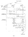
- FIG. 6 is a block diagram of an echo elimination device for a miniature hands-free voice communication system according to a preferred embodiment of the present invention, in a use state;
- FIG. 7 is a schematic diagram of a transfer function of each signal component from an auxiliary transmitter to a primary transmitter
- FIG. 8 is a schematic diagram of power curves of a signal of the primary transmitter and an array-filtered output signal
- FIG. 9 is a schematic diagram of power curves of an output signal of an array filter module and a first self-adaptive filter signal obtained by self-adaptive echo filtering;
- FIG. 10 is a schematic diagram of power curves of nonlinear echo components of a first self-adaptive filter signal and a second self-adaptive filter signal;
- FIG. 11 is a schematic diagram of a power curve of a nonlinear echo of a first self-adaptive filter signal and a power curve of a matched echo;
- FIG. 12( a ) is a schematic diagram of a power curve of a signal of a primary transmitter
- FIG. 12( b ) is a schematic diagram of a power curve of a near-end voice component in a signal of a primary transmitter
- FIG. 12( c ) is a schematic diagram of a power curve of an echo-eliminated output signal
- FIG. 13 is a flowchart of an echo elimination method for a miniature hands-free voice communication system according to a preferred embodiment of the present invention.
- FIG. 14 is a detailed flowchart of an echo elimination method for a miniature hands-free voice communication system according to a preferred embodiment of the present invention.
- FIG. 1 is a schematic diagram of positions of a receiver and transmitters applied by an echo elimination device and method for a miniature hands-free voice communication system according to the present invention.
- FIG. 2 is a schematic diagram of use of a small desktop hands-free voice communication system applied by an echo elimination device and method for a miniature hands-free voice communication system according to the present invention.
- FIG. 3 is a schematic diagram of use of a small vehicle hands-free voice communication system applied by an echo elimination device and method for a miniature hands-free voice communication system according to the present invention.
- the distances from the user to transmitters for example, microphones
- the near-end voice signals received by each transmitter from the user are basically identical.
- the distances from the receiver to the transmitters are not equal. If the distance from the receiver to a primary transmitter is D 1 and the distance from the receiver to an auxiliary transmitter is D 2 , and when D 1 >D 2 , the echo received by the two transmitters from the receiver has a difference in power, while the near-end voice received by the two transmitters from the user is nearly identical, so the voice may be distinguished from the echo according to the difference of power relations, so that the purpose of separating voice from echo is achieved.
- the present invention rightly utilizes the power difference to separate voice from echo.
- FIG. 4( a ) is a schematic diagram of power curves of echo components in signals of two transmitters
- FIG. 4( b ) is a schematic diagram of power curves of near-end voice components in signals of primary and auxiliary transmitters
- FIG. 4( c ) is a schematic diagram of power curves of an echo component and a near-end voice component in a primary transmitter.
- FIG. 5( a ) is a schematic diagram of a power curve of a signal of a primary transmitter
- FIG. 5( b ) is a schematic diagram of a power curve of an echo component of a primary transmitter
- FIG. 5( c ) is a schematic diagram of a power curve of a near-end voice component of a primary transmitter.
- the signals of the transmitters have the following characteristics:
- the echo components in the signals of the two transmitters have an obvious power difference, and the echo component in the signal of an auxiliary transmitter is, 6 dB or more, higher than that in the signal of a primary transmitter. This is because the echo power is approximately in inverse proportion to the distance from a transmitter to a receiver. As the distance from the auxiliary transmitter to the receiver is closer, the received echo is larger.
- the power of the near-end voice components in the signals of the transmitters is approximate. This is because the distances from the mouth of a near-end talker to the two transmitters are approximately equal in general applications. Therefore, the near-end voice power received by the two transmitters is also approximate.
- the power of the near-end voice is slightly about 3-6 dB lower than that of the echo.
- the near-end voice and the echo appear simultaneously, the near-end voice will be masked by the echo in some time-frequency regions.
- FIG. 6 is a block diagram of an echo elimination device for a miniature hands-free voice communication system provided by a preferred embodiment of the present invention, in a use state.
- FIG. 7 is a schematic diagram of a transfer function of each signal component from an auxiliary transmitter to a primary transmitter.
- FIG. 8 is a schematic diagram of power curves of a signal of the primary transmitter and an array-filtered output signal.
- FIG. 9 is a schematic diagram of power curves of an output signal of an array filter module and a first self-adaptive filter signal obtained by self-adaptive echo filtering.
- FIG. 10 is a schematic diagram of power curves of nonlinear echo components of a first self-adaptive filter signal and a second self-adaptive filter signal.
- FIG. 11 is a schematic diagram of a power curve of a nonlinear echo of the first self-adaptive filter signal and a power curve of a matched echo.
- FIG. 12( a ) is a schematic diagram of a power curve of a signal of a primary transmitter.
- FIG. 12( b ) is a schematic diagram of a power curve of a near-end voice component in a signal of a primary transmitter.
- FIG. 12( c ) is a schematic diagram of a power curve of an echo-eliminated output signal.
- the echo elimination device for a miniature hands-free voice communication system consists of an array echo elimination unit 610 , a self-adaptive echo elimination unit 620 and a residual echo elimination unit 630 .
- the array echo elimination unit 610 , the self-adaptive echo elimination unit 620 and the residual echo elimination unit 630 have a cascade relation in structure.
- the inputs of the array echo elimination unit 610 are a signal d 1 of a primary transmitter and a signal d 2 of an auxiliary transmitter.
- a path of output signal d 1 ′ is obtained by removing a part of linear echo component and a part of nonlinear echo component in the signal of the primary transmitter, by array filtering.
- the input signals of the self-adaptive echo elimination unit 620 are a signal x of the receiver, the output signal d 1 ′ of the array echo elimination unit 610 and a signal d 2 of the auxiliary transmitter.
- Two paths of output signals e 1 and e 2 are obtained by removing from the output signal d 1 ′ of the array echo elimination unit 610 a residual linear echo component in the signal of the primary transmitter, and removing from the signal d 2 of the auxiliary transmitter a linear echo component in the signal of the auxiliary transmitter, by self-adaptive filtering, respectively.
- the input signals of the residual echo elimination unit 630 are the two paths of output signals e 1 and e 2 from the self-adaptive echo elimination unit 620 .
- a residual nonlinear echo component in the signal of the primary transmitter is removed and then an output signal, i.e., an echo-separated voice signal, is output after echo elimination.
- an output signal i.e., an echo-separated voice signal
- the array echo elimination unit 610 the self-adaptive echo elimination unit 620 and the residual echo elimination unit 630 , the echo will be eliminated, while the near-end voice signal v will be reserved completely.
- the device includes an array filter module, two self-adaptive filter modules, two time-frequency transformation modules, a voice probability estimation module, a frequency spectrum filter module and a frequency-time transformation module.
- the array filter module includes an array filter 611 and a subtractor 612 .
- the array filter 611 is configured to perform array filtering to the signal d 2 of the auxiliary transmitter to obtain a second array filter signal.
- the subtractor 612 is configured to subtract the second array filter signal from the signal d 1 of the primary transmitter so as to remove a part of linear echo component and a part of nonlinear echo component in the signal of the primary transmitter and thus to obtain the output signal dr.
- the array filter has space directivity and may detect the sound emitted from the position of the receiver, and then a part of the sound emitted from the position of the receiver is eliminated by the subtractor. As both the linear echo component and the nonlinear echo component are emitted from the position of the receiver, a part of both the linear echo component and the nonlinear echo component will be removed after being processed by the array filter and the subtractor.
- the power of the echo component of d 1 ′ will be attenuated obviously, while the voice power does not change obviously.
- the principle is that, the receiver is close to the two transmitters in position and there is an obvious distance difference, while the near-end voice is far away from the two transmitters and has approximate distances.
- the transmission characteristics of the near-end voice and the echo to the transmitter are totally different, and this difference is reflected in transfer functions of the signals of the two transmitters. Through the difference between the transfer functions, the voice may be distinguished from the echo.
- the array filter 611 is designed according to the transfer function between the echo components, and the echo is removed by a manner of array filtering elimination, so that the near-end voice components will not be influenced.
- d echo1 is an echo component in the primary transmitter
- d sph1 is a near-end voice component in the signal of the primary transmitter
- d echo2 is an echo component in the auxiliary transmitter
- d sph2 is a near-end voice component in the signal of the auxiliary transmitter.
- E ⁇ ( h ⁇ - hN ) 2 > E ⁇ ( hN ) 2 ( 6 )
- a condition that h is totally different from hN is satisfied.
- Both h and hN are approximate to single-peak functions, where the width of a peak is about 0.25 ms, and the half width is about 0.125 ms. Due to the limitation of D 1 >2D 2 , the power difference between h and hN is above 6 dB, and the difference between the absolute values of peaks is more than two times.
- the transfer function of each signal component from the auxiliary transmitter to the primary transmitter may refer to FIG. 7 .
- the transfer function h between the echo components is expressed by a solid line and is a single-peak curve, and the peak is at a position where the time delay is (D 1 ⁇ D 2 )/c, where c denotes the propagation velocity of sound in the air, with the maximum amplitude being approximately D 2 /D 1 .
- the height of the peak is about 0.3, and the position of the peak is at 0.26 ms.
- the transfer function hN between the near-end voice components is a curve expressed by a dotted line, and is approximate to a single-peak curve in shape. The peak is at 0 ms, and the height of the peak is 1. It can be seen that the two transfer functions are totally different.
- the transfer function ⁇ of the array filter may be calculated offline in advance and fixed.
- the more accurate calculation may employ the least-mean-square-error criterion, as shown in formula (8), where ⁇ denotes the transfer function of the array filter, d 1 denotes the signal of the primary transmitter, d 2 denotes the signal of the auxiliary transmitter, E[.] denotes an expectation operation, and * denotes a convolution operation:
- the output d 1 ′ of the array filter module 610 is expressed by formula (3).
- the two self-adaptive filter modules both include a filter 621 , a filter controller 622 and a subtractor 623 , and are configured to perform, respectively, self-adaptive filtering to the signal d 2 of the auxiliary transmitter, to obtain a second self-adaptive filter signal e 2 so as to remove the linear echo component in the signal of the auxiliary transmitter, and perform self-adaptive filtering to the signal d 1 ′ obtained by subtracting the second array filter signal from the signal of the primary transmitter to obtain a first self-adaptive filter signal e 1 so as to remove the residual linear echo component in the signal of the primary transmitter.
- the self-adaptive echo elimination unit has three paths of inputs, i.e., the signal x of the receiver, the signal d 2 of the auxiliary transmitter and the output signal d 1 ′ of the array filter module.
- the outputs are the first self-adaptive filter signal e 1 and the second self-adaptive filter signal e 2 after self-adaptive filtering.
- the working principle of this part is similar to that of the universal self-adaptive echo filtering, and may employs time domain or frequency domain filtering.
- the two time-frequency transformation modules both include a data buffer 631 and a time-frequency transformer 632 , and are configured to perform, respectively, time-frequency transformation to the first self-adaptive filter signal e 1 to obtain a first self-adaptive frequency domain signal E 1 , and time-frequency transformation to the second self-adaptive filter signal e 2 to obtain a second self-adaptive frequency domain signal E 2 .
- the data buffers 631 are used for composing signals into signal vectors for allowing the time-frequency transformers 632 to use.
- the lengths of the data buffers 631 are set as L and related to computational resources, and may be set as 256 or 512 generally. If the input signals are e 1 ( n ) and e 2 ( n ) at the current moment n, the vectors formed in the two data buffers 631 are [e 1 ( n ⁇ L+1), e 1 ( n ⁇ L+2) . . . e 1 ( n )] and [e 2 ( n ⁇ L+1), e 2 ( n ⁇ L+2) . . . e 2 ( n )], respectively.
- the time-frequency transformers 632 transform the signals from time domain into frequency domain.
- the transformation may be realized by Fourier transform, improved discrete digital cosine transform or other ways.
- the frequency domain signals are:
- W exp ⁇ ( - j ⁇ 2 ⁇ ⁇ M ) .
- the voice probability estimation module 633 is configured to perform frequency domain voice probability estimation according to the amplitude of the first self-adaptive frequency domain signal E 1 and the amplitude of the second self-adaptive frequency domain signal E 2 to obtain a frequency domain voice probability signal pF, the frequency domain voice probability signal pF representing a proportion of a near-end voice signal in the first self-adaptive frequency domain signal E 1 . This is because:
- the voice probability estimation module 633 acquires the frequency domain voice probability information pF by comparing the amplitude relation of the two paths of signals, where pF is a time-frequency function and represents a proportion of voice and echo in each time-frequency region. If pF is 1, it is indicated that there are all near-end voice signals in this region. If pF is 0, it is indicated that there are all echo signals in this region. If pF is a value from 0 to 1, it is indicated that there are near-end voice signals and echo signals in this region. If pF is approximate to 1, it is indicated that the proportion of the near-end voice is large. If pF is approximate to 0, it is indicated that the proportion of the near-end voice is low.
- the working principle of the voice probability estimation is as follows: two paths of input signals E 1 and E 2 of the voice probability estimation module 633 both contains nonlinear echo components and near-end voice signals, where the power of the nonlinear echo component in E 1 is low, while the power of the nonlinear echo component in E 2 is about 20 dB higher than that of the nonlinear echo component in E 1 . Therefore, in a time-frequency region where the echo is located, the amplitude of E 2 is much higher that of E 1 . However, in a time-frequency region where the near-end voice is located, the power of E 1 is approximate to that of E 2 . By comparing the amplitude of E 1 with the amplitude of E 2 at each frequency point, the distribution of the nonlinear echo components and the near-end voice on a frequency may be known.
- the specific implementation method of this embodiment is as follows: calculating an amplitude ratio of E 1 to E 2 , and acquiring a voice probability according to the mapping relation:
- T S denotes an average amplitude difference between voice components in the signals of the two transmitters
- T E denotes an average amplitude difference of echo components in the signals of the two transmitters.
- T S and T E are related to a structure.
- T S 1.4
- the amplitude difference between the echo signals is D 1 /D 2 , then multiplied by the sensitivity tolerance 1.4, and rounded down so as to obtain 4.
- 2.6 is a difference between T S and T E , and is designed for making the function curve continuous.
- the meaning of this formula is that, when the amplitude difference of the signals is within 1.4, i.e., no more than the sensitivity tolerance, it is very likely to be the voice components, and the voice probability is 1.
- the amplitude difference of the signals is more than 4 and is approximate to the amplitude difference of the echo components, it is very likely to be the echo components, and the voice probability is 0.
- the middle part is fitted by a linear slope curve, so the probability value is lower if the amplitude difference is closer to 4.
- the calculation mode is:
- the frequency spectrum filter module includes an echo matcher 634 , a subtractor 635 and a multiplier 636 .
- the echo matcher 634 is configured to perform echo matching according to the power of the nonlinear echo component of the first self-adaptive frequency domain signal E 1 and the power of the nonlinear echo component of the second self-adaptive frequency domain signal E 2 to obtain a matched echo.
- the subtractor 635 is configured to subtract the matched echo from the first self-adaptive frequency domain signal E 1 .
- the multiplier 636 is configured to multiply the result of subtraction by the frequency domain voice probability signal pF.
- the echo matcher 634 may estimate nonlinear echo components and linear echo components from a frequency spectrum according to the interrelation between the nonlinear echo components and the linear echo components in the signals of the two transmitters, and then suppress them by filtering.
- the nonlinear echo components and the linear echo components are generated by the receiver and propagated to the primary transmitter and the auxiliary transmitter.
- the nonlinear echo components and the linear echo components in the signal d 1 of the primary transmitter and the signal d 2 of the auxiliary transmitters have high similarity. This similarity is mainly embodied as the consistency of spectrum peak positions of the nonlinear echo components and the linear echo components.
- the frequency distribution rules of the nonlinear echo components and the linear echo components are consistent if the positions of the spectrum peaks are consistent. If the spectrum peaks of the nonlinear echo components and the linear echo components are suppressed, majority of the nonlinear echo components and the linear echo components may be removed.
- Both the array echo elimination unit 610 and the self-adaptive echo elimination unit 620 perform linear filtering only, so that only the amplitude of the nonlinear echo components, the amplitude of the linear echo components and the enveloping shape of the frequency spectrum are changed, but the positions of the spectrum peaks are not changed, that is, the similarity relation of the nonlinear echo components and the linear echo components is still reserved. Therefore, in the first self-adaptive frequency domain signal E 1 and the second self-adaptive frequency domain signal E 2 , the positions of the spectrum peaks of the nonlinear echo components are highly approximate. It can be seen from the frequency spectrum shown in FIG. 10 that, the peak value positions of the nonlinear echo components and the linear echo components in E 1 and E 2 are identical or similar, except that the overall fluctuation shape and the signal power are different.
- overall outline matching may be performed to the nonlinear and linear echo components of E 1 and E 2 to obtain the matched echo, and then the matched echo is multiplied by a certain factor Ag for amplitude matching to obtain an amplitude-matched echo.
- the factor Ag declines with the rise of the voice probability pF.
- the amplitude of the matched echo is higher than that of the nonlinear and linear echo components; and, in a region having higher voice probability and lower echo probability, the amplitude obtained after multiplying the matched echo by Ag is equal to or slightly lower than that of the nonlinear and linear echo components.
- the interference of the residual echo to communication in pure echo is different from that in a double-taking.
- a person is very sensitive to the residual echo, and little residual echo will also discomfort the person.
- a person is not sensitive to the residual echo, but the quality of the near-end voice is highly required.
- the voice probability estimation module by a method combining voice probability estimation with echo matching, the value of the matched echo may be small, weaker frequency spectrum filtering may remove nonlinear and linear echo components, and the strength of frequency spectrum filtering changes with the near-end voice probability.
- the near-end voice probability is higher, the intensity of frequency spectrum filtering is reduced, to better protect the near-end voice.
- dynamically adjusting the filtering intensity along with the voice probability may enhance the comfort level and voice quality, so that the near-end voice may be betted reserved.
- the process of frequency spectrum filtering is: performing amplitude matching to the signal E 2 and the echo signal in E 1 .
- the amplitude matching may be performed in such a way: dividing a full frequency into M subbands with subband boundaries of B 1 ⁇ B M+1 .
- M may be 32 or 16.
- the power of each subband of E 1 and E 2 is acquired, and then division and evolution are performed to the power to obtain a matching function H m ⁇ E 2 is multiplied by the matching function H m and then multiplied by a factor Ag to obtain a matched echo Y m .
- the matching effect may refer to FIG. 11 . It can be seen that, within a frequency range where the echo is located, the matched echo Y m is approximate to the echo component of E 1 (the differences at 300 Hz and 3800 Hz are caused by the background noise, but are not matching errors).
- i ⁇ [1,M] denotes a subband number
- f denotes the frequency
- k denotes a frequency sampling point in a subband
- E 1 (k) denotes the amplitude of the first self-adaptive frequency domain signal at the frequency sampling point
- E 2 (k) denotes the amplitude of the second self-adaptive frequency domain signal at the frequency sampling point.
- the second self-adaptive frequency domain signal E 2 is multiplied by the matching function H m and then multiplied by a factor Ag for amplitude matching, to obtain a matched echo Y m :
- Y m ( f ) Ag ( f ) ⁇ E 2 ( f ) H m ( f )
- E 1 subtracts the matched echo Y m , and then multiplied by the voice probability function pF to obtain a result as follows: E out ( f )[ E 1 ( f ) ⁇ Y m ( f )] ⁇ pF ( f )
- the frequency-time transformation module 637 is configured to perform frequency-time transformation to the result of multiplication.
- the frequency-time transformation module 637 transforms a digital signal from a frequency domain into a time domain.
- the transformation may be realized by inverse Fourier transform, inverse discrete digital cosine transform or other ways.
- a frequency domain signal Eout is transformed into a time domain signal eout as a total output of the system.
- the final effect may refer to the signal d 1 of the primary transmitter in FIG. 12( a ) , the near-end voice component in the signal d 1 of the primary transmitter in FIG. 12( b ) , and the power curve of eout in FIG. 12( c ) . It can be seen that the echo components in the eout are all eliminated, and the near-end voice is completely reserved, and the signal power is not attenuated obviously in comparison to that of the original near-end voice component, thereby meeting the full-duplex requirements.
- FIG. 13 is a flowchart of an echo elimination method for a miniature hands-free voice communication system according to a preferred embodiment of the present invention.
- the miniature hands-free voice communication system includes a receiver, a primary transmitter and an auxiliary transmitter. A distance from the primary transmitter to the receiver is greater than that from the auxiliary transmitter to the receiver.
- the method includes the following steps of:
- S 1301 inputting a signal of the primary transmitter and a signal of the auxiliary transmitter into an array echo elimination unit, performing array filtering to remove a part of linear echo component and a part of nonlinear echo component in the signal of the primary transmitter to obtain one path of output signal;
- FIG. 14 is a detailed flowchart of an echo elimination method for a miniature hands-free voice communication system according to a preferred embodiment of the present invention.
- the miniature hands-free voice communication system includes a receiver, a primary transmitter and an auxiliary transmitter. A distance from the primary transmitter to the receiver is greater than that from the auxiliary transmitter to the receiver.
- the method includes the following steps of:
- the performing array filtering to the signal of the auxiliary transmitter to obtain a second array filter signal specifically includes: determining a transmission function ⁇ of an array filter, and performing array filtering to the signal of the auxiliary transmitter by an array filter using the transmission function ⁇ , where the transmission function ⁇ of the array filter is determined according to the following formula:
- ⁇ denotes the transmission function of the array filter
- d 1 denotes the signal of the primary transmitter
- d 2 denotes the signal of the auxiliary transmitter
- E[.] denotes an expectation operation symbol
- * denotes a convolution operation symbol.
- Step 1404 the performing frequency domain voice probability estimation according to the amplitude of the first self-adaptive frequency domain signal and the amplitude of the second self-adaptive frequency domain signal to obtain a frequency domain voice probability signal includes:
- T S denotes an average amplitude ratio of near-end voice signals in the signal of the auxiliary transmitter and the signal of the primary transmitter
- T E denotes an average amplitude ratio of nonlinear echo component signals in the signal of the auxiliary transmitter and the signal of the primary transmitter, wherein T E >T S >1.
- Step 1405 the performing echo matching to the second self-adaptive frequency domain signal according to the power of the nonlinear echo component of the first self-adaptive frequency domain signal and the power of the nonlinear echo component of the second self-adaptive frequency domain signal specifically includes the following two steps of:
- i ⁇ [1,M] denotes a subband number
- f denotes a frequency
- k denotes a frequency sampling point in a subband
- E 1 (k) denotes the amplitude of the first self-adaptive frequency domain signal at the frequency sampling point
- E 2 (k) denotes the amplitude of the second self-adaptive frequency domain signal at the frequency sampling point
- Ag When pF is close to 0, Ag is greater than 1, so that the amplitude of both the matched echo and Ag is higher than that of the nonlinear echo component of the first self-adaptive frequency domain signal E 1 , and the echo may be thus eliminated.
- Ag When pF is close to 1, Ag is a numerical value smaller than 1, so that the amplitude of the matched echo is lower than that of the nonlinear echo component of the first self-adaptive frequency domain signal E 1 , and the voice may be reserved.
- the matched echo is approximate to the residual nonlinear echo component in the first self-adaptive frequency domain signal, so the nonlinear echo component in the first self-adaptive frequency domain signal is almost subtracted completely after subtraction, but there may also weak residuals; and by multiplying the result of subtraction by the voice probability, the nonlinear echo component may be removed completely.
- the technical solutions of the present invention may be implemented only by a farthest transmitter and a nearest transmitter to a receiver, so it is easy to implement;
- the frequency domain voice probability signal is applied in the operation of the echo matching, so that the strength of frequency spectrum filtering changes with the near-end voice probability; and when the near-end voice probability is relatively high, the intensity of frequency spectrum filtering is reduced, so that the near-end voice may be better protected.
Landscapes
- Engineering & Computer Science (AREA)
- Signal Processing (AREA)
- Computer Networks & Wireless Communication (AREA)
- Cable Transmission Systems, Equalization Of Radio And Reduction Of Echo (AREA)
- Telephone Function (AREA)
- Circuit For Audible Band Transducer (AREA)
Applications Claiming Priority (4)
| Application Number | Priority Date | Filing Date | Title |
|---|---|---|---|
| CN201210556804.0A CN103051818B (zh) | 2012-12-20 | 2012-12-20 | 一种用于小型免提语音通讯系统中的回声消除装置和方法 |
| CN201210556804 | 2012-12-20 | ||
| CN201210556804.0 | 2012-12-20 | ||
| PCT/CN2013/001558 WO2014094359A1 (fr) | 2012-12-20 | 2013-12-12 | Dispositif d'annulation d'écho et procédé pour système de communication vocale à mains libres à petite échelle |
Publications (2)
| Publication Number | Publication Date |
|---|---|
| US20150172468A1 US20150172468A1 (en) | 2015-06-18 |
| US9325855B2 true US9325855B2 (en) | 2016-04-26 |
Family
ID=48064311
Family Applications (1)
| Application Number | Title | Priority Date | Filing Date |
|---|---|---|---|
| US14/411,669 Active US9325855B2 (en) | 2012-12-20 | 2013-12-12 | Echo elimination device and method for miniature hands-free voice communication system |
Country Status (7)
| Country | Link |
|---|---|
| US (1) | US9325855B2 (fr) |
| EP (1) | EP2858338B1 (fr) |
| JP (1) | JP5844502B2 (fr) |
| KR (1) | KR101532531B1 (fr) |
| CN (1) | CN103051818B (fr) |
| DK (1) | DK2858338T3 (fr) |
| WO (1) | WO2014094359A1 (fr) |
Families Citing this family (12)
| Publication number | Priority date | Publication date | Assignee | Title |
|---|---|---|---|---|
| CN103051818B (zh) | 2012-12-20 | 2014-10-29 | 歌尔声学股份有限公司 | 一种用于小型免提语音通讯系统中的回声消除装置和方法 |
| CN106576205B (zh) * | 2014-08-13 | 2019-06-21 | 三菱电机株式会社 | 回声消除装置 |
| GB2525051B (en) * | 2014-09-30 | 2016-04-13 | Imagination Tech Ltd | Detection of acoustic echo cancellation |
| CN105791515B (zh) * | 2014-12-22 | 2019-06-28 | 青岛海信移动通信技术股份有限公司 | 一种终端设备屏幕状态控制方法及终端设备 |
| US9607627B2 (en) * | 2015-02-05 | 2017-03-28 | Adobe Systems Incorporated | Sound enhancement through deverberation |
| JP2017191987A (ja) * | 2016-04-12 | 2017-10-19 | 日本電信電話株式会社 | エコー消去装置、その方法、プログラム、及び記録媒体 |
| CN107635082A (zh) * | 2016-07-18 | 2018-01-26 | 深圳市有信网络技术有限公司 | 一种双端发声端检测系统 |
| JP6954370B2 (ja) * | 2017-11-14 | 2021-10-27 | 日本電信電話株式会社 | 音声コミュニケーション装置、音声コミュニケーション方法、プログラム |
| MX2021013487A (es) * | 2019-05-09 | 2021-12-10 | Ericsson Telefon Ab L M | Sondeo de canales para transmision distribuida. |
| EP3793179A1 (fr) * | 2019-09-10 | 2021-03-17 | Peiker Acustic GmbH | Dispositif de communication vocale mains libres |
| CN113593589B (zh) | 2020-04-30 | 2022-06-28 | 阿波罗智联(北京)科技有限公司 | 回声时延检测方法、装置及电子设备 |
| CN116962583B (zh) * | 2023-09-20 | 2023-12-08 | 腾讯科技(深圳)有限公司 | 一种回声控制的方法、装置、设备、存储介质及程序产品 |
Citations (6)
| Publication number | Priority date | Publication date | Assignee | Title |
|---|---|---|---|---|
| US20030039353A1 (en) | 2001-08-13 | 2003-02-27 | Fujitsu Limited | Echo cancellation processing system |
| US20100189274A1 (en) * | 2007-06-21 | 2010-07-29 | Koninklijke Philips Electronics N.V. | Device for and a method of processing audio signals |
| US20100234720A1 (en) * | 2003-06-04 | 2010-09-16 | Tupin Jr Joe Paul | System and method for extracting physiological data using ultra-wideband radar and improved signal processing techniques |
| CN102387273A (zh) | 2011-07-08 | 2012-03-21 | 歌尔声学股份有限公司 | 一种抑制残留回声的方法和装置 |
| CN103051818A (zh) | 2012-12-20 | 2013-04-17 | 歌尔声学股份有限公司 | 一种用于小型免提语音通讯系统中的回声消除装置和方法 |
| US20140112467A1 (en) * | 2012-10-23 | 2014-04-24 | Interactive Intelligence, Inc. | System and Method for Acoustic Echo Cancellation |
Family Cites Families (6)
| Publication number | Priority date | Publication date | Assignee | Title |
|---|---|---|---|---|
| JP2004537219A (ja) * | 2001-07-20 | 2004-12-09 | コーニンクレッカ フィリップス エレクトロニクス エヌ ヴィ | 高調波計算のための非線形エコーサプレッサを備えたエコーキャンセラ |
| JP4709714B2 (ja) * | 2006-08-29 | 2011-06-22 | 日本電信電話株式会社 | エコー消去装置、その方法、そのプログラム、およびその記録媒体 |
| JP2008263441A (ja) * | 2007-04-12 | 2008-10-30 | Matsushita Electric Ind Co Ltd | 非線形エコーキャンセラ装置 |
| JP4700673B2 (ja) * | 2007-11-15 | 2011-06-15 | 日本電信電話株式会社 | エコー消去方法、装置、プログラム、および記録媒体 |
| CN202197344U (zh) * | 2011-07-08 | 2012-04-18 | 歌尔声学股份有限公司 | 送话器阵列回声消除系统 |
| CN203104592U (zh) * | 2012-12-20 | 2013-07-31 | 歌尔声学股份有限公司 | 一种用于小型免提语音通讯系统中的回声消除装置 |
-
2012
- 2012-12-20 CN CN201210556804.0A patent/CN103051818B/zh active Active
-
2013
- 2013-12-12 US US14/411,669 patent/US9325855B2/en active Active
- 2013-12-12 KR KR1020147037065A patent/KR101532531B1/ko active IP Right Grant
- 2013-12-12 JP JP2015524602A patent/JP5844502B2/ja active Active
- 2013-12-12 DK DK13864322.6T patent/DK2858338T3/en active
- 2013-12-12 WO PCT/CN2013/001558 patent/WO2014094359A1/fr active Application Filing
- 2013-12-12 EP EP13864322.6A patent/EP2858338B1/fr active Active
Patent Citations (6)
| Publication number | Priority date | Publication date | Assignee | Title |
|---|---|---|---|---|
| US20030039353A1 (en) | 2001-08-13 | 2003-02-27 | Fujitsu Limited | Echo cancellation processing system |
| US20100234720A1 (en) * | 2003-06-04 | 2010-09-16 | Tupin Jr Joe Paul | System and method for extracting physiological data using ultra-wideband radar and improved signal processing techniques |
| US20100189274A1 (en) * | 2007-06-21 | 2010-07-29 | Koninklijke Philips Electronics N.V. | Device for and a method of processing audio signals |
| CN102387273A (zh) | 2011-07-08 | 2012-03-21 | 歌尔声学股份有限公司 | 一种抑制残留回声的方法和装置 |
| US20140112467A1 (en) * | 2012-10-23 | 2014-04-24 | Interactive Intelligence, Inc. | System and Method for Acoustic Echo Cancellation |
| CN103051818A (zh) | 2012-12-20 | 2013-04-17 | 歌尔声学股份有限公司 | 一种用于小型免提语音通讯系统中的回声消除装置和方法 |
Non-Patent Citations (4)
| Title |
|---|
| CN 201210556804.0, Notification to Grant an Invention Patent, dated Aug. 5, 2014, 3 pages, and English Translation, 3 pages. |
| CN 201210556804.0, The First Office Action, Jan. 6, 2014, 7 pages, and English Translation, 8 pages. |
| CN 201210556804.0, The Second Office Action, Jun. 18, 2014, 3 pages, and English Translation, 3 pages. |
| PCT/CN2013/001558, Written Opinion dated Feb. 20, 2014, Chinese and English Versions, 14 pages. |
Also Published As
| Publication number | Publication date |
|---|---|
| KR101532531B1 (ko) | 2015-06-29 |
| KR20150008508A (ko) | 2015-01-22 |
| EP2858338B1 (fr) | 2017-08-23 |
| EP2858338A4 (fr) | 2015-12-09 |
| DK2858338T3 (en) | 2017-10-16 |
| EP2858338A1 (fr) | 2015-04-08 |
| WO2014094359A1 (fr) | 2014-06-26 |
| CN103051818B (zh) | 2014-10-29 |
| US20150172468A1 (en) | 2015-06-18 |
| JP2015526045A (ja) | 2015-09-07 |
| CN103051818A (zh) | 2013-04-17 |
| JP5844502B2 (ja) | 2016-01-20 |
Similar Documents
| Publication | Publication Date | Title |
|---|---|---|
| US9325855B2 (en) | Echo elimination device and method for miniature hands-free voice communication system | |
| US8175871B2 (en) | Apparatus and method of noise and echo reduction in multiple microphone audio systems | |
| CN108712703B (zh) | 低功耗的高效降噪耳机及降噪系统 | |
| US9685172B2 (en) | Method and device for suppressing residual echoes based on inverse transmitter receiver distance and delay for speech signals directly incident on a transmitter array | |
| CN104395957B (zh) | 一种通用可重构回声消除系统 | |
| US9343056B1 (en) | Wind noise detection and suppression | |
| US9768829B2 (en) | Methods for processing audio signals and circuit arrangements therefor | |
| CN109273019B (zh) | 用于回声抑制的双重通话检测的方法及回声抑制 | |
| US9049281B2 (en) | Nonlinear echo suppression | |
| CN104158990A (zh) | 用于处理音频信号的方法和音频接收电路 | |
| CN101958122B (zh) | 一种回声消除的方法和装置 | |
| US8712769B2 (en) | Apparatus and method for noise removal by spectral smoothing | |
| CN111756906B (zh) | 一种语音信号的回声抑制方法、装置和计算机可读介质 | |
| CN203104592U (zh) | 一种用于小型免提语音通讯系统中的回声消除装置 | |
| US8369511B2 (en) | Robust method of echo suppressor | |
| KR101550501B1 (ko) | 잔여 에코 제거 방법 및 그 장치 | |
| CN113327625A (zh) | 一种回声抑制方法、判定方法、介质及信号收发设备 | |
| CN115665327A (zh) | 一种语音回声的处理方法、装置、芯片及模组设备 | |
| Sudo et al. | Spectrum selective nonlinear echo suppression based on the amount of linear echo cancellation | |
| US20120224684A1 (en) | Soft attenuation of high-power signals |
Legal Events
| Date | Code | Title | Description |
|---|---|---|---|
| AS | Assignment |
Owner name: GOERTEK, INC., CHINA Free format text: ASSIGNMENT OF ASSIGNORS INTEREST;ASSIGNORS:LIU, SONG;LOU, SHASHA;LI, BO;REEL/FRAME:034948/0693 Effective date: 20150119 |
|
| STCF | Information on status: patent grant |
Free format text: PATENTED CASE |
|
| MAFP | Maintenance fee payment |
Free format text: PAYMENT OF MAINTENANCE FEE, 4TH YEAR, LARGE ENTITY (ORIGINAL EVENT CODE: M1551); ENTITY STATUS OF PATENT OWNER: LARGE ENTITY Year of fee payment: 4 |
|
| MAFP | Maintenance fee payment |
Free format text: PAYMENT OF MAINTENANCE FEE, 8TH YEAR, LARGE ENTITY (ORIGINAL EVENT CODE: M1552); ENTITY STATUS OF PATENT OWNER: LARGE ENTITY Year of fee payment: 8 |