US932518A - Safety-razor. - Google Patents
Safety-razor. Download PDFInfo
- Publication number
- US932518A US932518A US45814908A US1908458149A US932518A US 932518 A US932518 A US 932518A US 45814908 A US45814908 A US 45814908A US 1908458149 A US1908458149 A US 1908458149A US 932518 A US932518 A US 932518A
- Authority
- US
- United States
- Prior art keywords
- holder
- blade
- edge
- safety
- razor
- Prior art date
- Legal status (The legal status is an assumption and is not a legal conclusion. Google has not performed a legal analysis and makes no representation as to the accuracy of the status listed.)
- Expired - Lifetime
Links
Images
Classifications
-
- B—PERFORMING OPERATIONS; TRANSPORTING
- B26—HAND CUTTING TOOLS; CUTTING; SEVERING
- B26B—HAND-HELD CUTTING TOOLS NOT OTHERWISE PROVIDED FOR
- B26B21/00—Razors of the open or knife type; Safety razors or other shaving implements of the planing type; Hair-trimming devices involving a razor-blade; Equipment therefor
- B26B21/08—Razors of the open or knife type; Safety razors or other shaving implements of the planing type; Hair-trimming devices involving a razor-blade; Equipment therefor involving changeable blades
- B26B21/14—Safety razors with one or more blades arranged transversely to the handle
- B26B21/16—Safety razors with one or more blades arranged transversely to the handle involving blades with only one cutting edge
Definitions
- My invention relates to safety-razrs, and has for its object the provision of an improved simple, durable and highly efficient razor of this class, which is composedh of a minimum number of parts, is cheap of manufacture, and is capable of being easily and quickly assembled or ⁇ taken apart for vthe plliipose of cleaning or the removal of its ffffhe operation, construction and arrange-l niiit of thevparts of the invention are fully described in the following specification, and illustrated in the accompanying drawing, in which,
- Figure l is a front view of the bladeholder with the blade removed.
- Fig. 2 is a 'similar view of the holder with ⁇ the blade clamped in position thereon.
- Figs. 2l and 4 aredifferent side elevations of the holder and its handle.
- Fig. 5 is a view similar to Fig. 4t with the blade clamped in position thereon, and
- Figs. 6 and 7 are top lan and end views, respectively, of the bla e clamp, the "former having a portion broken away.
- 8 designates the; blade holder, which is preferably stainpied from sheet-metal and is carried at onefgend of a handle 9 which projects at an oblique angle from the-rear side thereof, as is dustomary in this class of razors.
- the rea edge of the holder 8 is formed with a shoulder 10 against which the rear edge of i Vthe tblade 11 abuts when in position, and
- the holder '8 is provided near-the forward edge thereof with the elongated opening 12, which extends to near each end of the holder and has.l its outer rim portion. forming an,l inte- Serrara-'Razon f1 l I ⁇ Specinrc-:attira of LettersPat-ent. Application led'ctober 17, 1908.7 Serial No. 458,149. p v
- the means employed ⁇ forfirmlyrgsecurimr;A ⁇ a blade to the holder comprises/ ai clan'ip-l of the same diameter throughout its lengt-1r; but has both edges thereof. offsinuons forma-f tion to give'the bar azjcomb effects Vlvithi. this construction of guard. asmooth.*surfaceis presented to the skin Vand kthe irritatingeffect on the skin of the combtype of guards heretofore commonly used avoided-.1 f Eaclixy forward cornery of the holder 8 is'fformedg.
- fcorn'ers"of-thea 15 of heet metal which has its ends bent down, as shown at 16, to embrace the ends of the holder and thenA bent to provide the inwardly projecting lips-17 which coperate with tongues 18 at the opposite ends of the y tightening of the clamp against the blade when the clamp is moved rearwardly on the holder with the lips 17 thereof in engagement with the tongues 18.
- the tongues 18 are provided at the rear ends of theirtapered edges withstop-lngs 19 to limit the rearward movement of the clamp thereon.
- a blade 11 is placed on the holder 8 with its rear edge in abutment with the shoulder 10 thereon and is then firmly clamped in position by placing the'clamp-bar 15 over the ho der and blade and moving it rearwardly thereon until thel lips 17 of its bent ends move along the tapered edges of the tongues 18 and are stopped by contact with the stoplugs 19, as shown in Fig. 5.
- the blade when in position on the holder has its cutting edge disposed over the opening 12 short of the forward edge thereof to permit lather which is scraped from the face to pass therethrough.
- a safety-razor comprlsing a holder stamped from slielmeta'l and having its 'rear 'edge bent up to form a blade-stop', ,its ends provided with ⁇ integral tongues which lare' bent down at right angles tothe holder face and'have their lower edges tapered relative' to the plane of the holder face, said holder also having-its forward portion pro- 'videdwith .an elongated opening, the outer of said o eni'ng being stamped t'o pro- -vide a: guardar having sinuous edges and "a smooth face contacting surface, a handle attached yto the holder, a blade carried by the holder; 'and a clamp-bar in removable 4sliding.en'gaggement wit *the holder and,
- a v'safety-razor comprising a holder .xstamped from vsheet-metal and provided at es of said tongue to vcausek the clamp to d the blade firmly to the holder.
Description
PL H. UNSINGER. SAFETY vRAZOR.
APPLIoATIon FILED 001217, 190e.
932.518. 4 v PatendAug-31, 1909.
Fg. Z
To allwhom it may concern:
Be 1t known that l, PHILIP H. UNSINGER,
a citizen' of the United States, and a resident of Fremont, iii-the county of Sandusky and State of Ohio, have invented a certain new and useful Safety- Razor; and' 1 .do hereby declare the following to be a full, clear, and exact description of the invention,
such as will enable others skilled in the art 1 to which 1t appertains to'inake and use the same, reference being had to the accompanying drawings, and to they figures of reference marked thereon, which form a part o'fthis specification. i 'if .1
My invention relates to safety-razrs, and has for its object the provision of an improved simple, durable and highly efficient razor of this class, which is composedh of a minimum number of parts, is cheap of manufacture, and is capable of being easily and quickly assembled or` taken apart for vthe plliipose of cleaning or the removal of its ffffhe operation, construction and arrange-l niiit of thevparts of the invention are fully described in the following specification, and illustrated in the accompanying drawing, in which,
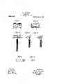
Figure l is a front view of the bladeholder with the blade removed. Fig. 2is a 'similar view of the holder with` the blade clamped in position thereon. Figs. 2l and 4 aredifferent side elevations of the holder and its handle. Fig. 5 is a view similar to Fig. 4t with the blade clamped in position thereon, and Figs. 6 and 7 are top lan and end views, respectively, of the bla e clamp, the "former having a portion broken away.
`Referring to the drawings, 8 designates the; blade holder, which is preferably stainpied from sheet-metal and is carried at onefgend of a handle 9 which projects at an oblique angle from the-rear side thereof, as is dustomary in this class of razors.
The rea edge of the holder 8 is formed with a shoulder 10 against which the rear edge of i Vthe tblade 11 abuts when in position, and
has its forward edge portion extended beyond the cutting edge of the blade and curved slightly inwardly,'or inthe direc- Y tion if the handle, to expose such cutting- `edge and formi a lguard therefor;
The holder '8 is provided near-the forward edge thereof with the elongated opening 12, which extends to near each end of the holder and has.l its outer rim portion. forming an,l inte- Serrara-'Razon f1 l I `Specinrc-:attira of LettersPat-ent. Application led'ctober 17, 1908.7 Serial No. 458,149. p v
-bladeto prevent cutting of tlfieffa'ce,the-robaT The means employed `forfirmlyrgsecurimr;A `a blade to the holder comprises/ ai clan'ip-l of the same diameter throughout its lengt-1r; but has both edges thereof. offsinuons forma-f tion to give'the bar azjcomb effects Vlvithi. this construction of guard. asmooth.*surfaceis presented to the skin Vand kthe irritatingeffect on the skin of the combtype of guards heretofore commonly used avoided-.1 f Eaclixy forward cornery of the holder 8 is'fformedg. with an integralspur 'o1-plug14,'wh-ichfis.::L gli; bentfover on the front facet-ofthe-fholdeif to forni 'guards for the sharp. fcorn'ers"of-thea 15 of heet metal, which has its ends bent down, as shown at 16, to embrace the ends of the holder and thenA bent to provide the inwardly projecting lips-17 which coperate with tongues 18 at the opposite ends of the y tightening of the clamp against the blade when the clamp is moved rearwardly on the holder with the lips 17 thereof in engagement with the tongues 18. The tongues 18 are provided at the rear ends of theirtapered edges withstop-lngs 19 to limit the rearward movement of the clamp thereon.
In the use of my invention, a blade 11 is placed on the holder 8 with its rear edge in abutment with the shoulder 10 thereon and is then firmly clamped in position by placing the'clamp-bar 15 over the ho der and blade and moving it rearwardly thereon until thel lips 17 of its bent ends move along the tapered edges of the tongues 18 and are stopped by contact with the stoplugs 19, as shown in Fig. 5. The blade when in position on the holder has its cutting edge disposed over the opening 12 short of the forward edge thereof to permit lather which is scraped from the face to pass therethrough.
l desire it to be understood that my invention is not limited to any specific form or arrangement of parts except in soffar as such'limitations are specified in the claims.
Having thus described my invention, what I claim as new and desire to secure by Lettersv Patent, is,--
1. A safety-razor, comprlsing a holder stamped from slielmeta'l and having its 'rear 'edge bent up to form a blade-stop', ,its ends provided with `integral tongues which lare' bent down at right angles tothe holder face and'have their lower edges tapered relative' to the plane of the holder face, said holder also having-its forward portion pro- 'videdwith .an elongated opening, the outer of said o eni'ng being stamped t'o pro- -vide a: guardar having sinuous edges and "a smooth face contacting surface, a handle attached yto the holder, a blade carried by the holder; 'and a clamp-bar in removable 4sliding.en'gaggement wit *the holder and,
adapted to bearagainst th blade and .hav-
ing' its' ends turned downwardly y, and in- Vwardly" to embrace the ends of the holder and' slidingly coperate with the tapered ed .ho
M2.' A v'safety-razor, comprising a holder .xstamped from vsheet-metal and provided at es of said tongue to vcausek the clamp to d the blade firmly to the holder.
its rear.. edge with a blade-stop, at its ends .l 'withintegral tongues which project down- 25'- Wardl'y at right-"angles to the Vholder-face :and have'their lower edges tapered relative to the plane of the holder face, and having its forward edge curved inwardly ,and provided with an elongated opening and itsv .edge disposed over said opening, and a clamp. havingrits ends bent to engage the tapered edge of said tongues and adapted'to coperate with the holderto clamp the blade thereto. Y*
In testimony whereof vI have hereunto signed my name to this specication in the presence of two subscribing witnesses.
PHILIP UNSINGER.
VVitnesses'p I PETER UNSINGER, M. I". ENGLER.
Priority Applications (1)
| Application Number | Priority Date | Filing Date | Title |
|---|---|---|---|
| US45814908A US932518A (en) | 1908-10-17 | 1908-10-17 | Safety-razor. |
Applications Claiming Priority (1)
| Application Number | Priority Date | Filing Date | Title |
|---|---|---|---|
| US45814908A US932518A (en) | 1908-10-17 | 1908-10-17 | Safety-razor. |
Publications (1)
| Publication Number | Publication Date |
|---|---|
| US932518A true US932518A (en) | 1909-08-31 |
Family
ID=3000941
Family Applications (1)
| Application Number | Title | Priority Date | Filing Date |
|---|---|---|---|
| US45814908A Expired - Lifetime US932518A (en) | 1908-10-17 | 1908-10-17 | Safety-razor. |
Country Status (1)
| Country | Link |
|---|---|
| US (1) | US932518A (en) |
-
1908
- 1908-10-17 US US45814908A patent/US932518A/en not_active Expired - Lifetime
Similar Documents
| Publication | Publication Date | Title |
|---|---|---|
| US20140345146A1 (en) | Utility knife | |
| US3626591A (en) | Safety razor with means for retracting guard plate | |
| US843148A (en) | Safety-razor. | |
| US932518A (en) | Safety-razor. | |
| US1092367A (en) | Safety-razor. | |
| US1111721A (en) | Safety-razor. | |
| US1044906A (en) | Razor. | |
| US1033373A (en) | Safety-razor. | |
| US1117953A (en) | Safety-razor. | |
| US2437896A (en) | Sliding wallpaper base trimmer | |
| US969724A (en) | Safety-razor. | |
| US1669711A (en) | Scraping tool | |
| US1048696A (en) | Safety-razor. | |
| US1092447A (en) | Glazier's tool. | |
| US1494998A (en) | Safety razor | |
| US2321895A (en) | Razor | |
| US887682A (en) | Device for stropping the blades of safety-razors. | |
| US1825494A (en) | Hair trimming attachment for safety razors | |
| US448159A (en) | Peter d | |
| US983640A (en) | Razor. | |
| US1006607A (en) | Safety-razor. | |
| US853960A (en) | Safety-razor. | |
| US840371A (en) | Razor. | |
| US808659A (en) | Holder and handle for safety-razors. | |
| US765391A (en) | Card bevel-edger. |