US932397A - Anchor. - Google Patents
Anchor. Download PDFInfo
- Publication number
- US932397A US932397A US45590108A US1908455901A US932397A US 932397 A US932397 A US 932397A US 45590108 A US45590108 A US 45590108A US 1908455901 A US1908455901 A US 1908455901A US 932397 A US932397 A US 932397A
- Authority
- US
- United States
- Prior art keywords
- link
- anchor
- perforation
- shank
- clip
- Prior art date
- Legal status (The legal status is an assumption and is not a legal conclusion. Google has not performed a legal analysis and makes no representation as to the accuracy of the status listed.)
- Expired - Lifetime
Links
- 210000005069 ears Anatomy 0.000 description 5
- 241000220010 Rhode Species 0.000 description 2
Images
Classifications
-
- B—PERFORMING OPERATIONS; TRANSPORTING
- B63—SHIPS OR OTHER WATERBORNE VESSELS; RELATED EQUIPMENT
- B63B—SHIPS OR OTHER WATERBORNE VESSELS; EQUIPMENT FOR SHIPPING
- B63B21/00—Tying-up; Shifting, towing, or pushing equipment; Anchoring
- B63B21/24—Anchors
- B63B21/243—Anchors foldable or capable of being disassembled
Definitions
- my invention consist-s in an improved means for securing the stock in the perforation of the head of the shank of the anchor, and in the improved ⁇ means for securing the end clip of the anchor chain, as hereinafter set forth.
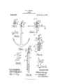
- Figure 1 represents the side view of an anchor' enrbodying my improvement.
- Fig. 2 represents a side view of the stock of the anchor, and the upper end of the shank.
- Fig.. 3 represents an edge view of the anchor with the stock folded at its side.
- Fig. 4 represents an enlarged section taken in the line 4, 4, of Fig. 2.
- Fig. 5, represents an enlarged View of the upper end of the shank, showing the side opening to receive the securing lug of the stock.
- Fig. G represents an enlarged side view of the securing link.
- Fig. 7 represents an enlarged perspective view of the chain clip.
- Fig. S represents an enlarged perspective view of the locking pin of the clip.
- A represents the shank of the anchor which is provided at its end with the holding ears B, B the ear B being provided with a circular perforation C to receive the cylindrical body of the stock D, while the ear B is provided with an elongated perforation E, adapted to receive the lug F, by means of which the stock is secured to the shank.
- the lug F is to be passed through the perforation E into the corresponding elongated perforation Gr made in the fastening' link I-I, the end I of which is loosely held in the slot opening J between the ears B, B, of the shank.
- the link H is adapted to receive the lug F only when the elongated perforation G of t-he link is made to register with the perforation E of the shank, as indicated by the dotted lines in Fig'. 4, so that when the link II is turned to the position shown in the several figures of the drawing, the stock which is in engage-y Specification of Letters Patent.
- the link H is to be turned from the position shown in full lines in Fig. 4, to the position shown by the dotted lines, and when in that position the lug F may be passed out of the perforations GA and E, and the stock turned as required.
- rIChe chain clip K is locked to the outer end of the link I-I, by means of the pin L, which is provided with the engaging lug M and the eye B.
- the said lug being adapted to enter the recess N made in the side of the perforation O, at the outer end of the link H, after the said lug has been passed through the corresponding recess ID made in the perforated ear Q of the chain clip K, the said chain clip being in this case turned to the position shown by the dotted lines inl Fig. 4. And when the clip has been turned up from the said position as shown by the full lines, the clip will be securely held to the link, and at the same time the cable chain may be readily unshackled from the anchor when required, by simply turning the clip back to its former position and then withdrawing the pin L by means of the projecting eye R.
Landscapes
- Chemical & Material Sciences (AREA)
- Engineering & Computer Science (AREA)
- Combustion & Propulsion (AREA)
- Mechanical Engineering (AREA)
- Ocean & Marine Engineering (AREA)
- Adornments (AREA)
Description
ANCHOR.
-APPLIGTION FILED lTVZ, 1903.
932,397, K Patented Aug. 24, `'1909;-
VVITNEESES. ai Inn/ENTER'.
ATTEJRNET .f
UNITED sTATEs PATENT oEEicE.
WILLIAM F. KENNEY, OF PROVIDENCE, RHODE ISLAND.
ANCHOR.
To all whom t may concern.'
Be it known that I, IViLLIAM F. KENNEY, a citizen of the United States, residing at Providence, in the State of Rhode Island, have invented a new and useful Improvement in Anchors, of which the following is a specification.
The nature of my invention consist-s in an improved means for securing the stock in the perforation of the head of the shank of the anchor, and in the improved `means for securing the end clip of the anchor chain, as hereinafter set forth.
In the accompanying drawing Figure 1 represents the side view of an anchor' enrbodying my improvement. Fig. 2 represents a side view of the stock of the anchor, and the upper end of the shank. Fig.. 3 represents an edge view of the anchor with the stock folded at its side. Fig. 4 represents an enlarged section taken in the line 4, 4, of Fig. 2. Fig. 5, represents an enlarged View of the upper end of the shank, showing the side opening to receive the securing lug of the stock. Fig. G represents an enlarged side view of the securing link. Fig. 7 represents an enlarged perspective view of the chain clip. Fig. S represents an enlarged perspective view of the locking pin of the clip.
In the drawing, A represents the shank of the anchor which is provided at its end with the holding ears B, B the ear B being provided with a circular perforation C to receive the cylindrical body of the stock D, while the ear B is provided with an elongated perforation E, adapted to receive the lug F, by means of which the stock is secured to the shank. The lug F, is to be passed through the perforation E into the corresponding elongated perforation Gr made in the fastening' link I-I, the end I of which is loosely held in the slot opening J between the ears B, B, of the shank. The link H is adapted to receive the lug F only when the elongated perforation G of t-he link is made to register with the perforation E of the shank, as indicated by the dotted lines in Fig'. 4, so that when the link II is turned to the position shown in the several figures of the drawing, the stock which is in engage-y Specification of Letters Patent.
Application filed October 2, 1908.
Patented Aug. 24,1909.
serial No. 455,901. l
ment with the link will be securely locked in its transverse position.
IWhenever it is desired to fold the stock in line with the shank, as shown in Fig. 3, the link H is to be turned from the position shown in full lines in Fig. 4, to the position shown by the dotted lines, and when in that position the lug F may be passed out of the perforations GA and E, and the stock turned as required. rIChe chain clip K is locked to the outer end of the link I-I, by means of the pin L, which is provided with the engaging lug M and the eye B. by means of which the pin is operated, the said lug being adapted to enter the recess N made in the side of the perforation O, at the outer end of the link H, after the said lug has been passed through the corresponding recess ID made in the perforated ear Q of the chain clip K, the said chain clip being in this case turned to the position shown by the dotted lines inl Fig. 4. And when the clip has been turned up from the said position as shown by the full lines, the clip will be securely held to the link, and at the same time the cable chain may be readily unshackled from the anchor when required, by simply turning the clip back to its former position and then withdrawing the pin L by means of the projecting eye R.
I claim as my invention:
l. In an anchor, the combination of the shank provided with the perforated ears, and having an elongated opening in one of the said ears, the link loosely held between the said ears, and provided with an elongated perforation corresponding to the perforation in the said ear of the shank, and the stock provided with a lug adapted to pass through the elongated perforation of the ear of the shank and into the corresponding perforation of the link, whereby when the said link is turned to its proper position the stock will be locked transversely of the shank and the stock will be in engagement with the link so as to turn therewith.
2. In an anchor, the combination of the chain clip provided with an ear having a recessed perforation and the link secured to the end of the shank of the anchor and provided with a perforation having a recess corresponding to that of the clip, and the pin proper position and provided with the ey provided with a lg adapted to pass through whereby the said engaging pin mary ybe opthe recess in the perforation of the ear of erated.
the chain clip andr into the corresponding l ,WILLIAM F. KENNEY. recess made in the perforation of the link to Witnesses :v receive it, thus securely fastening the clip to SOCRATES SCHOLFIELD,
the link when the said clip is turned to its BENJAMIN L. DENNIS.
Priority Applications (1)
| Application Number | Priority Date | Filing Date | Title |
|---|---|---|---|
| US45590108A US932397A (en) | 1908-10-02 | 1908-10-02 | Anchor. |
Applications Claiming Priority (1)
| Application Number | Priority Date | Filing Date | Title |
|---|---|---|---|
| US45590108A US932397A (en) | 1908-10-02 | 1908-10-02 | Anchor. |
Publications (1)
| Publication Number | Publication Date |
|---|---|
| US932397A true US932397A (en) | 1909-08-24 |
Family
ID=3000820
Family Applications (1)
| Application Number | Title | Priority Date | Filing Date |
|---|---|---|---|
| US45590108A Expired - Lifetime US932397A (en) | 1908-10-02 | 1908-10-02 | Anchor. |
Country Status (1)
| Country | Link |
|---|---|
| US (1) | US932397A (en) |
-
1908
- 1908-10-02 US US45590108A patent/US932397A/en not_active Expired - Lifetime
Similar Documents
| Publication | Publication Date | Title |
|---|---|---|
| US1205496A (en) | Rope-holder. | |
| US251464A (en) | Shackle | |
| US1539220A (en) | Key-ring holder | |
| US1241806A (en) | Snap-fastener. | |
| US1333375A (en) | Rope and cord fastener | |
| US1055008A (en) | Buckle. | |
| US765754A (en) | Key-ring. | |
| US355980A (en) | Clevis | |
| US1324927A (en) | Strap tightener and fastener | |
| US483450A (en) | Bag-fastener | |
| US722949A (en) | Rope-clamp. | |
| US652556A (en) | Snap-hook. | |
| US379613A (en) | Harness-buckle | |
| US1553256A (en) | Safety pin | |
| US1664198A (en) | Safety pin | |
| US966322A (en) | Harness-fastener. | |
| US499361A (en) | Snap-hook | |
| US1026452A (en) | Snap-hook. | |
| US736024A (en) | Seal-lock. | |
| US1187190A (en) | Safety-hasp. | |
| US185639A (en) | Improvement in snap-hooks | |
| US1191763A (en) | Cuff-button lock. | |
| US1079605A (en) | Trace-carrier. | |
| US894335A (en) | Hasp-fastener. | |
| US578895A (en) | John elias naudain |