US9315203B2 - Leveling railway vehicle and related systems and methods - Google Patents
Leveling railway vehicle and related systems and methods Download PDFInfo
- Publication number
- US9315203B2 US9315203B2 US14/000,472 US201214000472A US9315203B2 US 9315203 B2 US9315203 B2 US 9315203B2 US 201214000472 A US201214000472 A US 201214000472A US 9315203 B2 US9315203 B2 US 9315203B2
- Authority
- US
- United States
- Prior art keywords
- coil spring
- superstructure
- smls
- piston
- suspension
- Prior art date
- Legal status (The legal status is an assumption and is not a legal conclusion. Google has not performed a legal analysis and makes no representation as to the accuracy of the status listed.)
- Active
Links
- 238000000034 method Methods 0.000 title abstract description 6
- 239000000725 suspension Substances 0.000 claims abstract description 70
- 239000012530 fluid Substances 0.000 claims abstract description 24
- 238000004891 communication Methods 0.000 claims description 16
- 238000001125 extrusion Methods 0.000 claims description 15
- 238000013461 design Methods 0.000 description 3
- 238000006073 displacement reaction Methods 0.000 description 3
- 238000010586 diagram Methods 0.000 description 1
- 238000005516 engineering process Methods 0.000 description 1
- 230000006870 function Effects 0.000 description 1
- 230000008571 general function Effects 0.000 description 1
- 238000005259 measurement Methods 0.000 description 1
- 238000012544 monitoring process Methods 0.000 description 1
- 238000005086 pumping Methods 0.000 description 1
- 238000012163 sequencing technique Methods 0.000 description 1
- 238000012360 testing method Methods 0.000 description 1
Images


Classifications
-
- B—PERFORMING OPERATIONS; TRANSPORTING
- B61—RAILWAYS
- B61F—RAIL VEHICLE SUSPENSIONS, e.g. UNDERFRAMES, BOGIES OR ARRANGEMENTS OF WHEEL AXLES; RAIL VEHICLES FOR USE ON TRACKS OF DIFFERENT WIDTH; PREVENTING DERAILING OF RAIL VEHICLES; WHEEL GUARDS, OBSTRUCTION REMOVERS OR THE LIKE FOR RAIL VEHICLES
- B61F5/00—Constructional details of bogies; Connections between bogies and vehicle underframes; Arrangements or devices for adjusting or allowing self-adjustment of wheel axles or bogies when rounding curves
- B61F5/02—Arrangements permitting limited transverse relative movements between vehicle underframe or bolster and bogie; Connections between underframes and bogies
-
- B—PERFORMING OPERATIONS; TRANSPORTING
- B61—RAILWAYS
- B61B—RAILWAY SYSTEMS; EQUIPMENT THEREFOR NOT OTHERWISE PROVIDED FOR
- B61B1/00—General arrangement of stations, platforms, or sidings; Railway networks; Rail vehicle marshalling systems
- B61B1/02—General arrangement of stations and platforms including protection devices for the passengers
-
- B—PERFORMING OPERATIONS; TRANSPORTING
- B61—RAILWAYS
- B61F—RAIL VEHICLE SUSPENSIONS, e.g. UNDERFRAMES, BOGIES OR ARRANGEMENTS OF WHEEL AXLES; RAIL VEHICLES FOR USE ON TRACKS OF DIFFERENT WIDTH; PREVENTING DERAILING OF RAIL VEHICLES; WHEEL GUARDS, OBSTRUCTION REMOVERS OR THE LIKE FOR RAIL VEHICLES
- B61F5/00—Constructional details of bogies; Connections between bogies and vehicle underframes; Arrangements or devices for adjusting or allowing self-adjustment of wheel axles or bogies when rounding curves
- B61F5/02—Arrangements permitting limited transverse relative movements between vehicle underframe or bolster and bogie; Connections between underframes and bogies
- B61F5/14—Side bearings
-
- B—PERFORMING OPERATIONS; TRANSPORTING
- B61—RAILWAYS
- B61L—GUIDING RAILWAY TRAFFIC; ENSURING THE SAFETY OF RAILWAY TRAFFIC
- B61L99/00—Subject matter not provided for in other groups of this subclass
-
- F—MECHANICAL ENGINEERING; LIGHTING; HEATING; WEAPONS; BLASTING
- F16—ENGINEERING ELEMENTS AND UNITS; GENERAL MEASURES FOR PRODUCING AND MAINTAINING EFFECTIVE FUNCTIONING OF MACHINES OR INSTALLATIONS; THERMAL INSULATION IN GENERAL
- F16F—SPRINGS; SHOCK-ABSORBERS; MEANS FOR DAMPING VIBRATION
- F16F1/00—Springs
- F16F1/02—Springs made of steel or other material having low internal friction; Wound, torsion, leaf, cup, ring or the like springs, the material of the spring not being relevant
- F16F1/04—Wound springs
- F16F1/12—Attachments or mountings
- F16F1/121—Attachments or mountings adjustable, e.g. to modify spring characteristics
Definitions
- the current disclosure relates generally to leveling systems for railway vehicles, and more particularly to leveling secondary suspension systems for railway vehicles.
- railway vehicles particularly those used for public transportation, often include a superstructure for carrying passengers.
- the superstructure rides on a bogey, also sometimes referred to as a truck, which includes at least one wheel axle, more typically two, for traveling along the rails.
- a primary suspension system is positioned between the wheel axles and the bogey and a secondary suspension system is positioned between the bogey and superstructure.
- Superstructures have at least one access, e.g. a door, to allow passengers or cargo to enter or exit the superstructure when the railway vehicle reaches a loading platform. Because load may vary, the superstructure may sometimes need to lift or lower a variable distance to allow the floor of its access to reach the approximate level of the platform.
- the current disclosure is directed to, inter alia, systems and methods for leveling superstructures of a railway vehicle.
- leveling secondary suspension systems also referred to herein as “leveling suspensions” that allows for efficient leveling of the superstructure in a narrow geometric configuration that is readily integrated across a wide variety of bogey/superstructure designs.
- the current disclosure also includes a variety of methods and control system related to leveling suspensions.
- a railway vehicle in one example, includes a superstructure, a bogey, and a leveling suspension including at least one coil spring positioned between the superstructure and the bogey.
- a secondary suspension-mounting lift system (SMLS) is interfaced with coil spring.
- the SMLS includes a spring-mount (SM) and a piston assembly.
- SM spring-mount
- the railway vehicle comes to a stop at a station having a platform.
- a leveling sensor determines that the superstructure access door is below platform level. Pressurized hydraulic fluid acts on at least one piston and lifts the superstructure until the vehicles access door is at a predetermined level with respect to the platform level, e.g., approximately equal height as the platform level. After passenger or cargo loading and unloading, for example, fluid is released and the piston lowers the superstructure to the desired level.
- railway vehicles will include more than one leveling suspension, e.g., 2, 3, 4, 5, 6, 7, 8, etc.
- leveling suspensions may be positioned to raise the superstructure evenly, e.g., at least one of a front and back piston pressurized to raise the superstructure evenly and at least both sides pressured to raise the superstructure evenly.
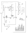
- FIG. 1 illustrates one example of a railway vehicle as disclosed herein having a leveling suspension system.
- FIG. 2 is a cutaway view of a leveling suspension system.
- FIG. 3 illustrates the leveling suspension of FIG. 2 in a different position.
- FIG. 4 is a diagram depicting the interface of a leveling suspension a HPU, and an ECU.
- FIG. 5 is a schematic depicting an SMLS, a HPU, an ECU, a TCU and a level sensor.
- FIG. 6 depicts a process flow example.
- FIG. 7 is a cutaway view of another example of a leveling secondary suspension system.
- FIG. 8 illustrates the suspension system FIG. 7 in a different position.
- FIG. 9 shows a perspective view of another example of a leveling suspension system.
- FIGS. 10 a and 10 b show side cutaway views of the system shown in FIG. 9 .
- FIG. 11 is a close-up view of the system shown in FIG. 9 .
- FIG. 12 shows a portion for receiving a leveling suspension system.
- FIG. 13 shows a leveling suspension system interfaced with a bogey.
- FIG. 14 shows an example of a leveling sensor.
- FIG. 1 illustrates a cutaway front view of railway vehicle 2 , which is one example of a railway vehicle disclosed herein.
- Vehicle 2 is shown positioned adjacent to platform 4 .
- vehicle 2 includes superstructure 6 and bogey 10 having wheel axle 12 .
- Superstructure 6 includes an access 6 a , e.g. a door, having an access floor 6 b .
- a primary suspension (not visible) is positioned between axle 12 and bogey 10 .
- a pair of leveling secondary suspension systems 15 are positioned between bogey 10 and superstructure 6 .
- Leveling secondary suspensions 15 include a spring 16 a interfaced with a suspension-mounting lift system (SMLS) 18 .
- SMLS suspension-mounting lift system
- the superstructure when traveling, the superstructure may be in a lowered coasting configuration (H c ) relative to the bogey.
- SMLS 18 When stopped at platform 4 , for example to load or unload, SMLS 18 may be used to raise superstructure 6 to reduce the distance D between platform level 4 a and access level 6 b . Raising and lowering may be achieved by a variety of SMLS examples.
- FIG. 2 illustrates a cut away side view of one example of a leveling suspension, referred to as leveling suspension 115 .
- leveling suspension 115 includes spring 116 a interfaced with SMLS 118 .
- An upper end of the leveling suspension 115 e.g. an upper surface of spring 116 a may be considered interfaced with superstructure 106 or configured to interface with a superstructure.
- a lower end 118 a of the SMLS may be considered interfaced with a bogey 110 or configured to attach to a bogey.
- SMLS is one example of an SMLS as disclosed herein, and may be considered a bottom mounting SMLS, because it is mounted to the bottom of spring 116 a.
- SMLS 118 includes spring-mount (SM) 120 and a piston assembly 122 .
- SM 120 includes hollow cylinder 120 a positioned within coil spring 116 a .
- SM also includes flange 120 b connected to the cylinder.
- Flange 120 b extends externally from the coil spring and abuts one end of the coil spring.
- flange 120 b abuts the bottom end of spring 116 a .
- flanges will be frictionally attached to the spring such that, for example, no hard connection between the spring and flange is required for positional and operational stability.
- SM 120 may also include expansion surface 120 c for increasing the effective area of the lift-force. As seen better in FIG. 3 , hydraulic fluid is capable of achieving fluid communication with, and acting on, expansion surface 120 c.
- Piston assembly 122 includes piston 122 a sized to fit within hollow cylinder 120 a . Piston assembly 122 also includes an extrusion 122 b for hydraulic interface, the extrusion being in fluid communication with the piston.
- FIG. 3 illustrates the leveling suspension 115 previously described, whereby pressurized hydraulic fluid inserted through extrusion 122 b acts on piston 122 a and lifts spring 116 a , thereby lifting the superstructure.
- the piston assembly may also include a stop, e.g., stop 122 c , to prevent the piston from extending beyond a predetermined distance.
- Leveling suspensions disclosed herein may be readily integrated with a variety of bogey/superstructure designs to provide a highly responsive and functional system in a narrow geometric space, which further eliminates the need for additional standalone leveling systems.
- FIG. 4 illustrates, generally, a lifting suspension 215 including spring 216 a interfaced with SMLS 218 ; a hydraulic power unit (HPU) 240 ; and an electronics control unit (ECU) 260 .
- ECU 260 sends signals to the HPU to raise or lower the SMLS, thereby allowing for the leveling of a superstructure.
- FIG. 5 illustrates another schematic including SMLS 318 , HPU 340 , and ECU 360 .
- At least one of a leveling sensor 362 and train control unit 364 may also be in communication with an ECU, as illustrated.
- accumulator 366 is shown as a discrete component in communication with the HPU, but in some examples, an accumulator may be an internal component of the HPU. Components of the schematic are briefly described in the legend.
- leveling sensors can include any device configured to determine the suspension settlement due to load, e.g., passenger load.
- a leveling sensor may include a superstructure-component for mounting to the superstructure, a bogey-component for mounting to the bogey, and a relative positioning device positioned to determine the movement of one component relative to another.
- Relative positioning devices may detect angular displacement, linear displacement, force, etc.
- systems may determine suspension settlement based on predefined settlement logic.
- Table 1 illustrates one prophetic example of settlement logic which may be used to determine suspension settlement and appropriate leveling.
- AW0 is pre-determined such that the superstructure access is about level with platform level.
- an output is generated.
- SMLS raises the superstructure about 0 mm.
- SMLS raises the superstructure about 5 mm.
- SMLS raises the superstructure about 25 mm.
- SMLS raises the superstructure about 35 mm.
- SMLS raises the superstructure about 40 mm.
- Table 1 represents just one example of logic. Logic may vary from example to example, and be readily determinable to one of ordinary skill in the art based on, inter alia, suspension design parameters and a known platform height.
- AW0 may be different for various platforms along a fine, with the AW0 being sequenced to correspond to line sequencing or detectable through a signal generating source at the platform.
- FIG. 6 illustrates one example of a process for operating components previously disclosed, e.g. in FIG. 5 .
- ECU 360 maintains system pressure, which may include monitoring the accumulator pressure transducer ( 9 ) and controlling the motor ( 5 ) to maintain correct system pressure.
- motor ( 5 ) drives pump ( 4 ), pumping fluid from reservoir ( 1 ) to accumulator ( 12 ), thereby building system pressure, which output by accumulator pressure transducer ( 9 ) in step 1 b.
- step 2 a railway vehicle comes to a stop at a station (See FIG. 1 for example).
- ECU 360 receives leveling command from TCU 364 .
- step 4 leveling input valves ( 14 ) open to allow fluid to the leveling actuators ( 19 ).
- step 4 a leveling pressure transducers ( 15 ) output the pressure in each leveling circuit.
- step 4 b relief valves ( 6 ) between the leveling circuits ensure that both sides of the superstructure are raised evenly. Level circuits may additionally determine that the front and back portions of the superstructure are raised evenly.
- ECU monitors leveling pressure transducers ( 15 ) as part of diagnostics.
- step 5 a fluid enters the leveling actuators ( 19 ), raising the superstructure to platform level.
- step 5 b ECU 360 monitors level sensor 362 to determine how much the vehicle needs to be raised.
- step 6 passengers enter or exit, the superstructure.
- step 7 ECU 360 receives propulsion command from TCU 364 .
- step 8 leveling output valves ( 16 ) dump fluid from leveling actuators ( 19 ) to reservoir ( 1 ).
- step 9 the vehicle goes into propulsion.
- FIGS. 7 and 8 illustrate leveling suspension system 415 , which is another example of a leveling suspension as disclosed herein.
- System 415 includes spring 416 a and SMLS 418 .
- SMLS 418 includes SM 420 and piston assembly 422 , with cylinder 420 a extending into the top of spring 416 a and flange 420 a abutting the top of spring 416 a .
- SMLS 418 may be considered a top mounted SMLS.
- FIG. 8 illustrates the leveling suspension 415 , whereby pressurized hydraulic fluid inserted through extrusion 422 b acts on piston 422 a and lifts upper end 416 a , thereby lifting the superstructure. Hydraulic fluid may also act on expansion surface 420 c.
- FIG. 9 illustrates a perspective view of a partial leveling system 515 , which is another example of a leveling suspension system as disclosed herein.
- Leveling system 515 includes SMLS 518 having SM 520 and piston assembly 522 .
- FIGS. 10 a and 10 b show side cutaway views of the system shown in FIG. 9 in a coasting configuration and a raised configuration, respectively.
- piston assembly 522 includes an angled extrusion 522 b .
- this example is shown as a bottom mount system, similar top mount systems are apparent based on the teachings contained herein.
- FIG. 11 shows a top view of a bogey section 610 , including a view of seat 630 for receiving, e.g. frictionally, a leveling system.
- FIG. 12 shows a side view of vehicle 700 and a close up partial view of vehicle 700 .
- Vehicle 700 includes a superstructure 706 having a pair of accesses 706 a .
- Leveling suspension systems 715 a and 715 b which may be considered similar to the system 515 previously described, are also visible.
- a pair of extrusions 722 b for receiving a flexible hydraulic line (not shown to facilitate viewing). Flexible lines may be used in many examples to accommodate the lifting of the superstructure and shimming of the suspension.
- superstructure 706 includes another pair of leveling suspension systems 715 c and 715 d on the opposite side (not shown).
- FIG. 13 illustrates one example of a leveling sensor, sensor 800 , which detects suspension settlement based on angular displacement.
- sensor 800 includes superstructure-component 800 a for mounting to the superstructure, a bogey-component 800 b for mounting to the bogey, and relative positioning device 810 positioned to determine the suspension settlement.
- Device 810 includes an arm 810 a that displaces along an angle ⁇ depending on superstructure load and suspension settlement.
- a milliamp signal sent from device 810 to an ECU may be proportional to angle ⁇ , thereby controlling the SMLS.
- Table 2 below illustrates one prophetic example of system logic which may be used to determine suspension settlement and appropriate leveling using leveling sensor 800 .
- AW0 is pre-determined such that the superstructure access is about level with platform level.
- an output is generated.
- device 810 a When arm 810 a is displaced an angle ⁇ that is less than ⁇ 25°, device 810 outputs 10 mA, and the SMLS raises the superstructure about 0 mm.
- arm 810 a When arm 810 a is displaced an angle ⁇ that is between ⁇ 25° and ⁇ 15, device 810 outputs 9 mA, and the SMLS raises the superstructure about 5 mm.
- arm 810 a is displaced an angle ⁇ that is between ⁇ 15° and ⁇ 5
- device 810 When arm 810 a is displaced an angle ⁇ that is between ⁇ 15° and ⁇ 5, device 810 outputs 8 mA, and the SMLS raises the superstructure about 25 mm.
Landscapes
- Engineering & Computer Science (AREA)
- Mechanical Engineering (AREA)
- General Engineering & Computer Science (AREA)
- Transportation (AREA)
- Vehicle Body Suspensions (AREA)
- Fluid-Damping Devices (AREA)
Abstract
Description
| TABLE 1 | |||
| Sensor | |||
| (degrees, mm, | |||
| Actual Mass | Suspension | pressure/unit, | ||
| Load Code | (kg) | Settlement | etc.) | Output |
| AW0 | 15,000 | 0 | mm | a | q |
| AW1 | 16,000 | 5 | mm | b | r |
| AW2 | 18,000 | 25 | mm | c | s |
| AW3 | 20,000 | 35 | mm | d | t |
| AW4 | 21,000 | 40 | mm | e | u |
| TABLE 2 | ||||
| Output | ||||
| Actual Mass | Suspension | Sensor | Current | |
| Load Code | (kg) | Settlement | (degrees) | (mA) |
| AW0 | 15,000 | 0 | mm | −25 | 10 |
| AW1 | 16,000 | 5 | mm | −15 | 9 |
| AW2 | 18,000 | 25 | mm | −5 | 8 |
| AW3 | 20,000 | 35 | mm | +5 | 7 |
| AW4 | 21,000 | 40 | mm | +8 | 6 |
Claims (32)
Priority Applications (1)
| Application Number | Priority Date | Filing Date | Title |
|---|---|---|---|
| US14/000,472 US9315203B2 (en) | 2011-02-22 | 2012-02-21 | Leveling railway vehicle and related systems and methods |
Applications Claiming Priority (3)
| Application Number | Priority Date | Filing Date | Title |
|---|---|---|---|
| US201161445252P | 2011-02-22 | 2011-02-22 | |
| PCT/US2012/025863 WO2012115927A1 (en) | 2011-02-22 | 2012-02-21 | Leveling railway vehicle and related systems and methods |
| US14/000,472 US9315203B2 (en) | 2011-02-22 | 2012-02-21 | Leveling railway vehicle and related systems and methods |
Publications (2)
| Publication Number | Publication Date |
|---|---|
| US20150021445A1 US20150021445A1 (en) | 2015-01-22 |
| US9315203B2 true US9315203B2 (en) | 2016-04-19 |
Family
ID=46721188
Family Applications (1)
| Application Number | Title | Priority Date | Filing Date |
|---|---|---|---|
| US14/000,472 Active US9315203B2 (en) | 2011-02-22 | 2012-02-21 | Leveling railway vehicle and related systems and methods |
Country Status (6)
| Country | Link |
|---|---|
| US (1) | US9315203B2 (en) |
| EP (1) | EP2678209A4 (en) |
| CN (1) | CN103534161B (en) |
| AU (1) | AU2012220826B2 (en) |
| CA (1) | CA2827898C (en) |
| WO (1) | WO2012115927A1 (en) |
Cited By (5)
| Publication number | Priority date | Publication date | Assignee | Title |
|---|---|---|---|---|
| DE102017107798A1 (en) | 2017-04-11 | 2018-10-11 | Knorr-Bremse Systeme für Schienenfahrzeuge GmbH | Level control system for a vehicle, in particular a rail vehicle |
| EP3483028A1 (en) | 2017-11-09 | 2019-05-15 | KNORR-BREMSE Systeme für Schienenfahrzeuge GmbH | Levelling system for a vehicle, in particular a rail vehicle |
| WO2019091635A1 (en) | 2017-11-09 | 2019-05-16 | Knorr-Bremse Systeme für Schienenfahrzeuge GmbH | Level control system for adjusting the level of a vehicle, in particular a rail vehicle |
| WO2019091637A1 (en) | 2017-11-09 | 2019-05-16 | Knorr-Bremse Systeme für Schienenfahrzeuge GmbH | Level control system for adjusting the level of a vehicle, in particular a rail vehicle |
| WO2019091636A1 (en) | 2017-11-09 | 2019-05-16 | Knorr-Bremse Systeme für Schienenfahrzeuge GmbH | Level control system for adjusting the level of a vehicle, in particular a rail vehicle |
Families Citing this family (10)
| Publication number | Priority date | Publication date | Assignee | Title |
|---|---|---|---|---|
| CA2827898C (en) * | 2011-02-22 | 2018-01-16 | Tec Tran Brake Corp. | Leveling railway vehicle and related systems and methods |
| DE102015013605B4 (en) * | 2015-10-21 | 2018-08-23 | Liebherr-Transportation Systems Gmbh & Co. Kg | leveling |
| FR3052423B1 (en) * | 2016-06-09 | 2018-07-06 | Alstom Transport Technologies | RAILWAY VEHICLE WITH LEVELING AND CIRCULATION METHOD THEREOF |
| FR3053301B1 (en) * | 2016-06-29 | 2019-05-24 | Alstom Transport Technologies | METHOD FOR CONTROLLING THE HEIGHT OF A TRANSPORT VEHICLE AND ASSOCIATED TRANSPORT VEHICLE |
| US10442448B2 (en) * | 2017-03-08 | 2019-10-15 | Bombardier Transportation Gmbh | Height adjustable secondary suspension for a rail vehicle |
| CN107161168A (en) * | 2017-05-26 | 2017-09-15 | 华东交通大学 | Rail smooth degree on train bogie dynamically adjusts adaptive device and control method |
| FR3080077B1 (en) * | 2018-04-17 | 2020-09-18 | Alstom Transp Tech | RAILWAY VEHICLE AND ASSOCIATED CIRCULATION METHOD |
| CN109017819B (en) * | 2018-08-29 | 2019-11-22 | 中车青岛四方机车车辆股份有限公司 | Height adjustment system and height adjustment method |
| CN109050578B (en) * | 2018-08-29 | 2020-01-10 | 中车青岛四方机车车辆股份有限公司 | Method and system for controlling lifting of rail vehicle |
| ES2915425A1 (en) * | 2020-12-22 | 2022-06-22 | Patentes Talgo S L U | Railway box lifting system (Machine-translation by Google Translate, not legally binding) |
Citations (21)
| Publication number | Priority date | Publication date | Assignee | Title |
|---|---|---|---|---|
| US4368672A (en) * | 1980-12-29 | 1983-01-18 | The Budd Company | Secondary suspension system for a railway car |
| US4505457A (en) * | 1981-06-05 | 1985-03-19 | Kawasaki Jukogyo Kabushiki Kaisha | Railway truck spring height adjustment device |
| US5558368A (en) * | 1994-11-03 | 1996-09-24 | Deere & Company | Chassis structure |
| US5769400A (en) * | 1992-10-13 | 1998-06-23 | Knorr-Bremse Ag | Height and inclination control of a wagon body |
| US6103278A (en) * | 1999-01-12 | 2000-08-15 | Lluch; Alex | Lenticular lollipop |
| US6550394B1 (en) * | 2002-03-11 | 2003-04-22 | Buckeye Steel Castings Company | Retractable auxiliary bumper for hydraulic or pneumatic railway suspensions |
| US20030107161A1 (en) * | 2001-12-11 | 2003-06-12 | Martin Teichmann | Spring suspension device |
| US20040016361A1 (en) * | 2002-04-26 | 2004-01-29 | Martin Teichmann | Level control for a rail-mounted vehicle |
| JP2005125958A (en) | 2003-10-24 | 2005-05-19 | Sumitomo Rubber Ind Ltd | Suspension device |
| US7168370B2 (en) * | 2003-12-22 | 2007-01-30 | Knorr-Bremse Systeme für Schienenfahrzeuge GmbH | System for the secondary suspension of a superstructure of a rail vehicle having an active spring element |
| US20070035103A1 (en) * | 2005-06-23 | 2007-02-15 | Gaile Anton | Spring system |
| US7185592B2 (en) * | 2003-12-22 | 2007-03-06 | Knorr-Bremse Systeme Fur Schienenfahrzeuge Gmbh | System for the secondary suspension of a superstructure of a rail vehicle having a passive spring element |
| US7243606B2 (en) * | 2003-12-22 | 2007-07-17 | Knorr-Bremse Systeme Fur Schienenfahrzeuge Gmbh | System for the secondary suspension of a superstructure of a rail vehicle having an active spring element |
| US20080210119A1 (en) * | 2005-04-22 | 2008-09-04 | Knorr-Bremse Systeme Fur Schenenfahrzeuge Gmbh | Device For Secondary Suspension of a Car Body in a Rail Vehicle |
| US7520494B2 (en) * | 2002-08-20 | 2009-04-21 | Liebherr-Aerospace Lindenberg Gmbh | Spring element |
| JP2010076608A (en) | 2008-09-26 | 2010-04-08 | Toyo Tire & Rubber Co Ltd | Air spring and height adjustment method for railway vehicle |
| US8079310B2 (en) | 2009-11-25 | 2011-12-20 | LTK Consulting Services, Inc. | Vertical position compensating device for a vehicle |
| WO2012025863A1 (en) | 2010-08-23 | 2012-03-01 | Telefonaktiebolaget L M Ericsson (Publ) | Multi-tier micro-ring resonator optical interconnect system |
| US20120167797A1 (en) | 2010-12-31 | 2012-07-05 | Bret Worden | Dynamic weight management for a vehicle via hydraulic actuators |
| US8899159B2 (en) * | 2009-09-30 | 2014-12-02 | Bombardier Transportation Gmbh | Spring assembly for level control in a vehicle |
| US20150021445A1 (en) * | 2011-02-22 | 2015-01-22 | James Franks | Leveling railway vehicle and related systems and methods |
Family Cites Families (2)
| Publication number | Priority date | Publication date | Assignee | Title |
|---|---|---|---|---|
| DE10315000A1 (en) * | 2002-04-26 | 2003-11-06 | Siemens Sgp Verkehrstech Gmbh | Rail vehicle has actuator(s) between wagon box and underbody for bringing wagon box from raised traveling position to lowered loading/unloading position against restoring force of spring stage |
| CN1788171A (en) * | 2003-06-04 | 2006-06-14 | 凤凰股份有限公司 | Spring device, especially for the rail vehicle sector |
-
2012
- 2012-02-21 CA CA2827898A patent/CA2827898C/en not_active Expired - Fee Related
- 2012-02-21 US US14/000,472 patent/US9315203B2/en active Active
- 2012-02-21 CN CN201280019518.9A patent/CN103534161B/en not_active Expired - Fee Related
- 2012-02-21 AU AU2012220826A patent/AU2012220826B2/en not_active Ceased
- 2012-02-21 EP EP12750089.0A patent/EP2678209A4/en not_active Withdrawn
- 2012-02-21 WO PCT/US2012/025863 patent/WO2012115927A1/en not_active Ceased
Patent Citations (22)
| Publication number | Priority date | Publication date | Assignee | Title |
|---|---|---|---|---|
| US4368672A (en) * | 1980-12-29 | 1983-01-18 | The Budd Company | Secondary suspension system for a railway car |
| US4505457A (en) * | 1981-06-05 | 1985-03-19 | Kawasaki Jukogyo Kabushiki Kaisha | Railway truck spring height adjustment device |
| US5769400A (en) * | 1992-10-13 | 1998-06-23 | Knorr-Bremse Ag | Height and inclination control of a wagon body |
| US5558368A (en) * | 1994-11-03 | 1996-09-24 | Deere & Company | Chassis structure |
| US6103278A (en) * | 1999-01-12 | 2000-08-15 | Lluch; Alex | Lenticular lollipop |
| US20030107161A1 (en) * | 2001-12-11 | 2003-06-12 | Martin Teichmann | Spring suspension device |
| US6550394B1 (en) * | 2002-03-11 | 2003-04-22 | Buckeye Steel Castings Company | Retractable auxiliary bumper for hydraulic or pneumatic railway suspensions |
| US20040016361A1 (en) * | 2002-04-26 | 2004-01-29 | Martin Teichmann | Level control for a rail-mounted vehicle |
| US7520494B2 (en) * | 2002-08-20 | 2009-04-21 | Liebherr-Aerospace Lindenberg Gmbh | Spring element |
| JP2005125958A (en) | 2003-10-24 | 2005-05-19 | Sumitomo Rubber Ind Ltd | Suspension device |
| US7168370B2 (en) * | 2003-12-22 | 2007-01-30 | Knorr-Bremse Systeme für Schienenfahrzeuge GmbH | System for the secondary suspension of a superstructure of a rail vehicle having an active spring element |
| US7185592B2 (en) * | 2003-12-22 | 2007-03-06 | Knorr-Bremse Systeme Fur Schienenfahrzeuge Gmbh | System for the secondary suspension of a superstructure of a rail vehicle having a passive spring element |
| US7243606B2 (en) * | 2003-12-22 | 2007-07-17 | Knorr-Bremse Systeme Fur Schienenfahrzeuge Gmbh | System for the secondary suspension of a superstructure of a rail vehicle having an active spring element |
| US20080210119A1 (en) * | 2005-04-22 | 2008-09-04 | Knorr-Bremse Systeme Fur Schenenfahrzeuge Gmbh | Device For Secondary Suspension of a Car Body in a Rail Vehicle |
| US20070035103A1 (en) * | 2005-06-23 | 2007-02-15 | Gaile Anton | Spring system |
| US8235366B2 (en) | 2005-06-23 | 2012-08-07 | Liebherr Aerospace Lindenberg GmbH | Spring system |
| JP2010076608A (en) | 2008-09-26 | 2010-04-08 | Toyo Tire & Rubber Co Ltd | Air spring and height adjustment method for railway vehicle |
| US8899159B2 (en) * | 2009-09-30 | 2014-12-02 | Bombardier Transportation Gmbh | Spring assembly for level control in a vehicle |
| US8079310B2 (en) | 2009-11-25 | 2011-12-20 | LTK Consulting Services, Inc. | Vertical position compensating device for a vehicle |
| WO2012025863A1 (en) | 2010-08-23 | 2012-03-01 | Telefonaktiebolaget L M Ericsson (Publ) | Multi-tier micro-ring resonator optical interconnect system |
| US20120167797A1 (en) | 2010-12-31 | 2012-07-05 | Bret Worden | Dynamic weight management for a vehicle via hydraulic actuators |
| US20150021445A1 (en) * | 2011-02-22 | 2015-01-22 | James Franks | Leveling railway vehicle and related systems and methods |
Non-Patent Citations (1)
| Title |
|---|
| Wikipedia page on Honda Stepwgn-admitted prior art. |
Cited By (11)
| Publication number | Priority date | Publication date | Assignee | Title |
|---|---|---|---|---|
| DE102017107798A1 (en) | 2017-04-11 | 2018-10-11 | Knorr-Bremse Systeme für Schienenfahrzeuge GmbH | Level control system for a vehicle, in particular a rail vehicle |
| WO2018189072A1 (en) | 2017-04-11 | 2018-10-18 | Knorr-Bremse Systeme für Schienenfahrzeuge GmbH | Level control system for a vehicle, in particular a rail vehicle |
| US11459001B2 (en) * | 2017-04-11 | 2022-10-04 | Knorr-Bremse Systeme für Schienenfahrzeuge GmbH | Level control system for a vehicle, in particular a rail vehicle |
| EP3483028A1 (en) | 2017-11-09 | 2019-05-15 | KNORR-BREMSE Systeme für Schienenfahrzeuge GmbH | Levelling system for a vehicle, in particular a rail vehicle |
| WO2019091635A1 (en) | 2017-11-09 | 2019-05-16 | Knorr-Bremse Systeme für Schienenfahrzeuge GmbH | Level control system for adjusting the level of a vehicle, in particular a rail vehicle |
| WO2019091638A1 (en) | 2017-11-09 | 2019-05-16 | Knorr-Bremse Systeme für Schienenfahrzeuge GmbH | Levelling system for a vehicle, in particular a rail vehicle |
| WO2019091637A1 (en) | 2017-11-09 | 2019-05-16 | Knorr-Bremse Systeme für Schienenfahrzeuge GmbH | Level control system for adjusting the level of a vehicle, in particular a rail vehicle |
| WO2019091636A1 (en) | 2017-11-09 | 2019-05-16 | Knorr-Bremse Systeme für Schienenfahrzeuge GmbH | Level control system for adjusting the level of a vehicle, in particular a rail vehicle |
| US11420657B2 (en) | 2017-11-09 | 2022-08-23 | Knorr-Bremse Systeme für Schienenfahrzeuge GmbH | Levelling system for a vehicle, in particular a rail vehicle |
| US11608093B2 (en) * | 2017-11-09 | 2023-03-21 | Knorr-Bremse Systeme für Schienenfahrzeuge GmbH | Level control system for adjusting the level of a vehicle |
| US11787450B2 (en) | 2017-11-09 | 2023-10-17 | Knorr-Bremse Systeme für Schienenfahrzeuge GmbH | Level control system for adjusting the level of a vehicle, in particular a rail vehicle |
Also Published As
| Publication number | Publication date |
|---|---|
| CA2827898A1 (en) | 2012-08-30 |
| AU2012220826A1 (en) | 2013-08-29 |
| EP2678209A4 (en) | 2017-11-22 |
| US20150021445A1 (en) | 2015-01-22 |
| AU2012220826B2 (en) | 2016-08-04 |
| EP2678209A1 (en) | 2014-01-01 |
| WO2012115927A1 (en) | 2012-08-30 |
| CN103534161B (en) | 2016-10-26 |
| CN103534161A (en) | 2014-01-22 |
| CA2827898C (en) | 2018-01-16 |
Similar Documents
| Publication | Publication Date | Title |
|---|---|---|
| US9315203B2 (en) | Leveling railway vehicle and related systems and methods | |
| US8683927B2 (en) | Railroad car wheel truck | |
| AU2010297329B2 (en) | Suspension failure detection in a rail vehicle | |
| US8899159B2 (en) | Spring assembly for level control in a vehicle | |
| EP4273419A1 (en) | Air spring and railway vehicle | |
| AU2023200975B2 (en) | Railway wagon for transportation of semitrailers and the like | |
| CN110386163B (en) | Railway vehicle and related transportation method | |
| US10442448B2 (en) | Height adjustable secondary suspension for a rail vehicle | |
| US7185592B2 (en) | System for the secondary suspension of a superstructure of a rail vehicle having a passive spring element | |
| US8636416B2 (en) | Lower side bearing for railroad car wheel truck | |
| CN108349511B (en) | Leveling device | |
| CN107299786A (en) | One kind has multi-functional carrier vehicle device | |
| US20170355386A1 (en) | Rail vehicle provided with a leveling and associated running method | |
| ATE407046T1 (en) | LIFTING DEVICE BUILT INTO A SYSTEM FOR THE SWIVELING LOADING PLATFORM OF A LOW FLOOR WAGON DESIGNED FOR THE TRANSPORT OF SEMI-TRAILERS | |
| KR102652017B1 (en) | System for vehicles multiple shock absorber | |
| US20060195240A1 (en) | Secondary suspension element for a rail vehicle | |
| KR102263173B1 (en) | Freight load detection system applied to intermodal automatic freight transportation system | |
| JP6838925B2 (en) | Secondary suspension system for railroad vehicles | |
| CN112519819B (en) | Bogie and rail vehicle | |
| DE10296950B4 (en) | Arrangement for a commercial vehicle and a commercial vehicle | |
| RU67044U1 (en) | LATERAL SUPPORT OF THE CARGO WAGON (OPTIONS) | |
| CN223592342U (en) | Lifting conveying equipment, lifting transfer trolley and roller assembly | |
| RU2790995C2 (en) | Railway car for transportation of semitrailers and vehicle similar to semitrailer | |
| US11618485B2 (en) | End guide system and method for a truck assembly of a rail vehicle | |
| CN214141432U (en) | Steering wheel suspension system and intelligent navigation transport vehicle |
Legal Events
| Date | Code | Title | Description |
|---|---|---|---|
| AS | Assignment |
Owner name: TEC TRAN BRAKE CORP., NORTH CAROLINA Free format text: ASSIGNMENT OF ASSIGNORS INTEREST;ASSIGNORS:FRANKS, JAMES;KOHLER, ADAM W.;REEL/FRAME:030941/0826 Effective date: 20120622 |
|
| AS | Assignment |
Owner name: KCKB CORP., PENNSYLVANIA Free format text: CHANGE OF NAME;ASSIGNOR:TEC TRAN BRAKE CORP.;REEL/FRAME:030965/0429 Effective date: 20120712 |
|
| AS | Assignment |
Owner name: WABTEC HOLDING CORP., PENNSYLVANIA Free format text: ASSIGNMENT OF ASSIGNORS INTEREST;ASSIGNOR:KCKB CORP.;REEL/FRAME:030961/0579 Effective date: 20130807 |
|
| AS | Assignment |
Owner name: TEC TRAN BRAKE CORP., NORTH CAROLINA Free format text: ASSIGNMENT OF ASSIGNORS INTEREST;ASSIGNORS:FRANKS, JAMES;KOHLER, ADAM W.;REEL/FRAME:031920/0631 Effective date: 20120622 Owner name: KCKB CORP, NORTH CAROLINA Free format text: CHANGE OF NAME;ASSIGNOR:TEC TRAN BRAKE CORP.;REEL/FRAME:031946/0082 Effective date: 20120712 |
|
| AS | Assignment |
Owner name: WABTEC HOLDING CORP., PENNSYLVANIA Free format text: NUNC PRO TUNC ASSIGNMENT;ASSIGNOR:KCKB CORP.;REEL/FRAME:031929/0548 Effective date: 20130708 |
|
| FEPP | Fee payment procedure |
Free format text: PAYOR NUMBER ASSIGNED (ORIGINAL EVENT CODE: ASPN); ENTITY STATUS OF PATENT OWNER: LARGE ENTITY |
|
| STCF | Information on status: patent grant |
Free format text: PATENTED CASE |
|
| MAFP | Maintenance fee payment |
Free format text: PAYMENT OF MAINTENANCE FEE, 4TH YEAR, LARGE ENTITY (ORIGINAL EVENT CODE: M1551); ENTITY STATUS OF PATENT OWNER: LARGE ENTITY Year of fee payment: 4 |
|
| MAFP | Maintenance fee payment |
Free format text: PAYMENT OF MAINTENANCE FEE, 8TH YEAR, LARGE ENTITY (ORIGINAL EVENT CODE: M1552); ENTITY STATUS OF PATENT OWNER: LARGE ENTITY Year of fee payment: 8 |