US9312112B2 - Evacuating a sample chamber - Google Patents
Evacuating a sample chamber Download PDFInfo
- Publication number
- US9312112B2 US9312112B2 US13/348,390 US201213348390A US9312112B2 US 9312112 B2 US9312112 B2 US 9312112B2 US 201213348390 A US201213348390 A US 201213348390A US 9312112 B2 US9312112 B2 US 9312112B2
- Authority
- US
- United States
- Prior art keywords
- collector
- sample
- sample chamber
- time period
- compound
- Prior art date
- Legal status (The legal status is an assumption and is not a legal conclusion. Google has not performed a legal analysis and makes no representation as to the accuracy of the status listed.)
- Active, expires
Links
- 238000010438 heat treatment Methods 0.000 claims abstract description 91
- 239000000126 substance Substances 0.000 claims description 50
- 150000001875 compounds Chemical class 0.000 claims description 49
- 238000000034 method Methods 0.000 claims description 37
- 239000000758 substrate Substances 0.000 claims description 8
- 230000004044 response Effects 0.000 claims description 6
- 238000003780 insertion Methods 0.000 claims description 5
- 230000037431 insertion Effects 0.000 claims description 5
- 230000004888 barrier function Effects 0.000 claims description 4
- 239000002594 sorbent Substances 0.000 claims description 4
- 238000001514 detection method Methods 0.000 description 21
- 238000012546 transfer Methods 0.000 description 12
- 239000012491 analyte Substances 0.000 description 6
- 239000002360 explosive Substances 0.000 description 6
- 230000001965 increasing effect Effects 0.000 description 6
- 239000011159 matrix material Substances 0.000 description 6
- 230000008569 process Effects 0.000 description 6
- 230000035945 sensitivity Effects 0.000 description 6
- 238000010586 diagram Methods 0.000 description 5
- 238000005070 sampling Methods 0.000 description 5
- 238000009835 boiling Methods 0.000 description 4
- 239000000356 contaminant Substances 0.000 description 4
- 230000003247 decreasing effect Effects 0.000 description 4
- 238000010926 purge Methods 0.000 description 4
- 239000004744 fabric Substances 0.000 description 3
- 239000000463 material Substances 0.000 description 3
- 238000005259 measurement Methods 0.000 description 3
- 230000007246 mechanism Effects 0.000 description 3
- OKTJSMMVPCPJKN-UHFFFAOYSA-N Carbon Chemical compound [C] OKTJSMMVPCPJKN-UHFFFAOYSA-N 0.000 description 2
- VYPSYNLAJGMNEJ-UHFFFAOYSA-N Silicium dioxide Chemical compound O=[Si]=O VYPSYNLAJGMNEJ-UHFFFAOYSA-N 0.000 description 2
- 239000012298 atmosphere Substances 0.000 description 2
- 230000008901 benefit Effects 0.000 description 2
- 229910052799 carbon Inorganic materials 0.000 description 2
- 230000007423 decrease Effects 0.000 description 2
- 239000004205 dimethyl polysiloxane Substances 0.000 description 2
- 230000000694 effects Effects 0.000 description 2
- -1 for example Substances 0.000 description 2
- 239000005350 fused silica glass Substances 0.000 description 2
- 229910001120 nichrome Inorganic materials 0.000 description 2
- 229920000435 poly(dimethylsiloxane) Polymers 0.000 description 2
- 239000013076 target substance Substances 0.000 description 2
- 238000009834 vaporization Methods 0.000 description 2
- 230000008016 vaporization Effects 0.000 description 2
- 239000012855 volatile organic compound Substances 0.000 description 2
- 229920000742 Cotton Polymers 0.000 description 1
- 239000004793 Polystyrene Substances 0.000 description 1
- 239000002575 chemical warfare agent Substances 0.000 description 1
- 239000011248 coating agent Substances 0.000 description 1
- 238000000576 coating method Methods 0.000 description 1
- 239000004020 conductor Substances 0.000 description 1
- 239000000470 constituent Substances 0.000 description 1
- 238000011109 contamination Methods 0.000 description 1
- 230000008878 coupling Effects 0.000 description 1
- 238000010168 coupling process Methods 0.000 description 1
- 238000005859 coupling reaction Methods 0.000 description 1
- 238000000151 deposition Methods 0.000 description 1
- 238000007598 dipping method Methods 0.000 description 1
- 230000007613 environmental effect Effects 0.000 description 1
- 239000000835 fiber Substances 0.000 description 1
- 231100001261 hazardous Toxicity 0.000 description 1
- 239000004009 herbicide Substances 0.000 description 1
- 229930195733 hydrocarbon Natural products 0.000 description 1
- 150000002430 hydrocarbons Chemical class 0.000 description 1
- 230000001939 inductive effect Effects 0.000 description 1
- 239000003317 industrial substance Substances 0.000 description 1
- 229910001092 metal group alloy Inorganic materials 0.000 description 1
- 238000012986 modification Methods 0.000 description 1
- 230000004048 modification Effects 0.000 description 1
- 238000012544 monitoring process Methods 0.000 description 1
- 239000004081 narcotic agent Substances 0.000 description 1
- 239000000575 pesticide Substances 0.000 description 1
- 238000009428 plumbing Methods 0.000 description 1
- 229920002223 polystyrene Polymers 0.000 description 1
- 238000003825 pressing Methods 0.000 description 1
- 230000009467 reduction Effects 0.000 description 1
- 238000002470 solid-phase micro-extraction Methods 0.000 description 1
- 238000010897 surface acoustic wave method Methods 0.000 description 1
- 231100000331 toxic Toxicity 0.000 description 1
- 230000002588 toxic effect Effects 0.000 description 1
Images


Classifications
-
- H—ELECTRICITY
- H01—ELECTRIC ELEMENTS
- H01J—ELECTRIC DISCHARGE TUBES OR DISCHARGE LAMPS
- H01J49/00—Particle spectrometers or separator tubes
- H01J49/02—Details
- H01J49/04—Arrangements for introducing or extracting samples to be analysed, e.g. vacuum locks; Arrangements for external adjustment of electron- or ion-optical components
- H01J49/0468—Arrangements for introducing or extracting samples to be analysed, e.g. vacuum locks; Arrangements for external adjustment of electron- or ion-optical components with means for heating or cooling the sample
- H01J49/049—Arrangements for introducing or extracting samples to be analysed, e.g. vacuum locks; Arrangements for external adjustment of electron- or ion-optical components with means for heating or cooling the sample with means for applying heat to desorb the sample; Evaporation
-
- G—PHYSICS
- G01—MEASURING; TESTING
- G01N—INVESTIGATING OR ANALYSING MATERIALS BY DETERMINING THEIR CHEMICAL OR PHYSICAL PROPERTIES
- G01N1/00—Sampling; Preparing specimens for investigation
- G01N1/28—Preparing specimens for investigation including physical details of (bio-)chemical methods covered elsewhere, e.g. G01N33/50, C12Q
- G01N1/40—Concentrating samples
- G01N1/405—Concentrating samples by adsorption or absorption
-
- G—PHYSICS
- G01—MEASURING; TESTING
- G01N—INVESTIGATING OR ANALYSING MATERIALS BY DETERMINING THEIR CHEMICAL OR PHYSICAL PROPERTIES
- G01N1/00—Sampling; Preparing specimens for investigation
- G01N1/02—Devices for withdrawing samples
- G01N2001/028—Sampling from a surface, swabbing, vaporising
Definitions
- This disclosure is related to the field of chemical analysis and detection, and more particularly to the use of a sample collection and introduction system that utilizes a sample collector inserted into a sample chamber and chamber evacuation techniques to increase the concentration of a sample introduced to a detection device such as a mass spectrometer.
- Chemical analysis tools such as gas chromatographs (“GC”), mass spectrometers (“MS”), ion mobility spectrometers (“IMS”), and various others, are commonly used to identify trace amounts of chemicals, including, for example, chemical warfare agents, explosives, narcotics, toxic industrial chemicals, volatile organic compounds, semi-volatile organic compounds, hydrocarbons, airborne contaminants, herbicides, pesticides, and various other hazardous contaminant emissions.
- GC gas chromatographs
- MS mass spectrometers
- IMS ion mobility spectrometers
- detection typically involves the use of a swab or pad to capture the sample, and in some cases, involves heating the collector to release or vaporize the sample, thereby releasing it into an ambient gas matrix (e.g., air) before being transferred into the chemical detector.
- an ambient gas matrix e.g., air
- Implementations of the present disclosure are directed to devices, systems, and techniques for facilitating the rapid detection of particulates or chemicals captured in a collector (e.g., a swab, pad, cloth, wipe, vial, substrate) by increasing the effective concentration of the sample as seen by a chemical detector.
- a collector e.g., a swab, pad, cloth, wipe, vial, substrate
- the effective concentration of a sample captured in or on a collector is increased by enclosing the collector in a sample chamber, evacuating the chamber to reduce an internal pressure of the chamber to a level substantially less than the pressure of the surrounding atmosphere, heating the collector to release the sample, and introducing the sample into the mass spectrometer.
- transferring a sample into a mass spectrometer is accomplished by capturing a sample on a collector; inserting the collector into a sample chamber coupled to the mass spectrometer and a vacuum pump; evacuating the sample chamber using the vacuum pump to reduce an internal pressure of the sample chamber to a level less than atmospheric pressure; heating the collector to release the sample from the collector; and introducing the sample into the mass spectrometer from the evacuated sample chamber.
- a sample analysis system includes a sample chamber configured to receive a collector carrying a sample, the sample chamber including a base and a lid operable to access a cavity formed by the base and the lid; a vacuum pump coupled to the sample chamber and configured to evacuate the sample chamber to reduce an internal pressure of the sample chamber to a level less than atmospheric pressure; a heating element configured to heat the collector to release the sample from the collector into the evacuated sample chamber; and a chemical analyzer coupled to the sample chamber and configured to receive the sample from the evacuated sample chamber.
- a sample chamber in another general aspect, includes a base and a lid forming a cavity configured to receive a collector carrying a sample; and a heating element configured to heat the collector to release the sample from the collector; wherein the sample chamber is configured to be coupled to a vacuum pump operable to evacuate the sample chamber to reduce an internal pressure of the sample chamber to a level less than atmospheric pressure prior to the release of the sample from the collector.
- the collector can include a sorbent material; capturing the sample on the collector may include wiping a surface of a target object with the collector, depositing the sample on the collector, or submerging at least a portion of the collector into a target substance; inserting the collector into the sample chamber may include forming a substantially air-tight seal around the collector when inserted into the sample chamber and/or pressing the collector against a heating element; heating the collector may include conducting current through a heating element to induce Joule heating; determining a temperature of the collector based on a measured resistance of the heating element; heating the collector may include emitting radiant energy substantially toward the collector using one or more heating elements, and/or reflecting the emitted radiant energy substantially toward the collector using a reflective barrier; the radiant heating element may be configured to emit radiant energy of a particular wavelength that preferentially excites a sample of interest; the collector may be a wipe, a substrate, or a swab; the sample chamber may include one or
- FIG. 1 is a system diagram of an exemplar chemical detection system.
- FIGS. 2, 3, and 4 are cross-sectional views of exemplar sample chambers.
- FIG. 5 is a system diagram of another exemplar chemical detection system.
- FIGS. 6A-6C are perspective and cross-sectional views of an exemplar sample chamber.
- FIG. 7 is a process flow diagram illustrating an example technique for detecting particulates/chemicals captured in or on a collector.
- FIG. 8 is a system diagram of an exemplar arrangement of a chemical detection system.
- FIG. 9 is an exemplar process flow 400 for using a chemical detection system to transfer a collected sample into a chemical analyzer for analysis.
- Mass spectrometers are particularly well suited for chemical analysis due to the high resolution measurements that can be realized and because mass spectrometers measure a fundamental property of chemicals that are introduced into the instrument.
- Other forms of chemical analysis instrumentation such as ion mobility spectrometers, surface acoustic wave devices, electrochemical cells, and similar instruments measure the constituents of a sample by inferring their presence from measurements of related phenomena such as resonant frequency changes, voltage changes, and drift time measurements.
- mass spectrometers typically require a vacuum environment (e.g., pressures of 10 ⁇ 6 -10 ⁇ 3 Torr) for proper operation.
- the number of molecules present is further decreased by miniaturization of the mass spectrometer (i.e., decreased V) to enable easy portability, for example, by airport security personnel.
- V the mass spectrometer
- the effect of reducing the detection volume of the instrument is a reduction in the sensitivity of the instrument, where the sensitivity is the minimum external amount of a sample that can be measured by the instrument.
- a mass spectrometer operating at 10 ⁇ 3 Torr, with an analysis chamber volume of 1 mm 3 operating at 25° C. will have 32.3 ⁇ 10 9 molecules present.
- a corresponding instrument that operates at atmospheric pressure (760 Torr) will have 24.6 ⁇ 10 15 molecules present.
- a corresponding instrument that operates at 10 ⁇ 3 Torr but has an analysis chamber that is 1 cm 3 will have 32 ⁇ 10 12 molecules present.
- miniaturizing instruments that operate at lower pressures significantly reduces the number of molecules available for analysis.
- detection typically involves the use of a surface wipe, for example, to collect the sample, and in some cases, involves heating the collector to release or vaporize the sample, which may or may not decompose into more primitive components during the release/vaporization, into an ambient gas matrix (e.g., air) before being transferred into the chemical detector.
- an ambient gas matrix e.g., air
- the present disclosure provides alternative techniques for improving the sensitivity of a mass spectrometer in detecting chemicals/particulates captured in a collector without a significant increase in analysis time.
- the effective concentration of the sample can be increased over that of a sample introduced from a non-evacuated chamber.
- Table 1 illustrates a sample calculation showing net gain that can be achieved by evacuation of the dead volume.
- the effective concentration of the sample is substantially increased.
- the ratio of analyte molecules to the total number of molecules in the volume is effectively increased.
- the accuracy of the analysis is typically improved.
- evacuation of the sampling system improves the operation of the detection system by reducing contamination of the transfer path and/or the heat requirements for the transfer path.
- Explosives are very “sticky” compounds.
- the transfer paths are typically heated to prevent the explosive vapors from sticking or condensing to the transfer lines.
- Compounds are much less likely to stick to or condense in a transfer path when the pressure in the transfer path is reduced to or near the vapor pressure of the compound in question and the temperature of the transfer path is near or above the corresponding boiling point, which will generally be much lower than the boiling point at atmospheric pressure.
- the boiling point temperature of a compound decreases as the environmental pressure surrounding the compound decreases.
- the evacuation of the sampling system in combination with the heating phase of the sampling process reduces or eliminates the need for lengthy purge cycles between samplings, thereby improving the system's purge efficiency.
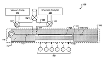
- FIG. 1 illustrates an exemplar chemical detection system (CDS) 100 configured to facilitate the rapid detection of particulates/chemicals at extremely low concentrations while reducing heat requirements for a transfer path between a sample chamber and a chemical detector and improving the system's purge efficiency.
- CDS 100 includes a sample chamber 110 (shown in cross-sectional form) having a base 112 and a lid 114 .
- Base 112 and lid 114 define a substantially air-tight cavity 111 configured to receive a collector 125 containing a surface-wiped, adsorbed, or absorbed sample.
- base 112 and lid 114 are mechanically coupled, for example, by a hinge 116 (as shown in FIG. 1 ) or other similar mechanisms, such that the two portions can be separated to allow access to cavity 111 for the insertion and removal of collector 125 .
- FIG. 2 is a cross-section view of sample chamber 110 when opened.
- gasket 113 is inserted in a groove 115 A defined by base 112 .
- lid 114 may also define a groove 115 B positioned opposite groove 115 A to receive gasket or seal 113 .
- sample chamber 110 is coupled to a vacuum path 130 via a vacuum port 117 defined by lid 114 .
- vacuum port 117 is defined by base 112 , for example, to limit the flexing of vacuum plumbing forming vacuum path 130 .
- vacuum port 117 is located adjacent to cavity 111 to facilitate the evacuation of the dead volume within the cavity by a vacuum pump 140 coupled to vacuum path 130 via a valve 133 .
- Vacuum path 130 is also coupled to a chemical analyzer 150 via a valve 132 .
- Valve 132 is operable to isolate an inlet port or analysis chamber of chemical analyzer 150 from sample chamber 110 , for example, before the evacuation of the dead volume within the cavity.
- Valve 134 is operable to re-pressurize sample chamber 110 after the analysis to allow an operator to open the sample chamber, extract the collector, and insert the next sample.
- Other arrangements are also possible, including, for example, evacuating sample chamber 110 using a vacuum pump system coupled directly to chemical analyzer 150 , or evacuating sample chamber 110 via a separate vacuum path coupled to vacuum pump 140 .
- FIG. 8 illustrates another possible arrangement.
- the sample is released by heating collector 125 .
- heating of the collector 125 is accomplished by utilizing infrared heating elements 160 , as illustrated in FIG. 1 .
- the infrared heating elements are positioned so that they emit radiant energy substantially toward collector 125 through a substrate 118 (e.g., fused quartz window) forming a portion of base 112 .
- one or more infrared wavelengths are chosen to preferentially excite particular compounds of interest.
- Other techniques or materials may also be used to effect the release or vaporization of the sample from collector 125 , including, for example, the use of a conductive heating element heated by Joule heating, described in more detail below.
- electrical current is passed through an electrically conductive collector, such as a carbon cloth, in order to heat the collector and release the analyte.
- the heating element is controlled such that the temperature imparted upon the collector, which may contain a plurality of analytes (e.g., compounds of interest) having different boiling points at the pressure present in cavity 111 , allows one or more of the analytes to be released while retaining one or more analytes.
- the temperature of collector 125 is adjusted in a pattern, and valve 132 is operated, such that analytes are released and introduced into chemical analyzer 150 at different times.
- the pressure of cavity 111 is adjusted in a pattern, with either substantially constant temperature or a corresponding temperature profile, to allow selective release of analyte from collector 125 .
- the analyte can be released via a variety of mechanisms, including, for example, controlling the temperature of a conductive heating element by adjusting voltage and current, and hence energy density (Joule heating), adjusting the frequency, wavelength, or intensity of a radiant source (for example infrared diodes), modulating the pulse width and/or frequency of a radiant source (PWM), and similar techniques.
- Other techniques for adjusting the temperature of collector 125 can be realized without changing the scope of this disclosure.
- FIGS. 3 and 4 illustrate alternative implementations of sample chamber 110 in which lid 114 includes a substrate 119 (e.g., fused quartz window). As illustrated in FIG. 3 , in some implementations, substrate 119 includes mirror backing 120 such that radiant energy emitted by infrared heating elements 160 is reflected back towards collector 125 . FIG. 4 illustrates another alternative implementation in which a second set of infrared heating elements 162 is positioned adjacent substrate 119 so that they emit radiant energy substantially toward collector 125 through substrate 119 . In some implementations, infrared heating elements 160 are embedded or included in base 112 and/or lid 114 .
- substrate 119 e.g., fused quartz window
- substrate 119 includes mirror backing 120 such that radiant energy emitted by infrared heating elements 160 is reflected back towards collector 125 .
- FIG. 4 illustrates another alternative implementation in which a second set of infrared heating elements 162 is positioned adjacent substrate 119 so that they emit radiant energy substantially toward collector 125 through substrate 119 .
- FIG. 5 illustrates another exemplar chemical detection system (CDS) 200 configured to facilitate the rapid detection of chemicals at extremely low concentrations while reducing heat requirements for a transfer path between a sample chamber and a chemical detector and improving the system's purge efficiency.
- CDS 200 includes a sample chamber 210 (shown in cross-sectional form) having a base 212 and a lid 214 .
- Base 212 and lid 214 define a substantially air-tight cavity 211 configured to receive a collector 225 containing a surface-wiped sample.
- base 212 and lid 214 are mechanically coupled, for example, by a hinge 216 (as shown in FIG.
- sample chamber 210 When sample chamber 210 is closed, a substantially air-tight seal is formed between the base 212 and lid 214 , for example, by gasket 213 .
- FIGS. 6A-6C are perspective/cross-sectional views of sample chamber 210 when opened.
- gasket or seal 213 is inserted in a groove 215 A defined by base 212 .
- lid 214 may also define a groove 215 B positioned opposite groove 215 A to receive gasket or seal 213 .
- sample chamber 210 is coupled to vacuum path 230 and vacuum pump 240 via valve 233 and a vacuum port 217 defined by base 212 to facilitate the evacuation of the dead volume within cavity 211 .
- Vacuum path 230 is also coupled to a chemical analyzer 250 via a valve 232 .
- Valve 232 is operable to isolate the analysis chamber of chemical analyzer 250 from sample chamber 210 , for example, before the evacuation of the dead volume within the cavity. After cavity 211 has been evacuated, valve 232 is opened and the sample is released or vaporized by heating collector 225 . In some implementations, valve 232 remains closed until the completion of the heating phase.
- Valve 234 is operable to re-pressurize sample chamber 210 after the analysis to allow an operator to open the sample chamber, extract the collector, and insert the next sample.
- other arrangements are also possible, including, for example, evacuating sample chamber 210 using a vacuum pump coupled directly to chemical analyzer 250 , or evacuating sample chamber 210 via a separate vacuum path coupled to vacuum pump 240 .
- FIG. 8 illustrates another possible arrangement.
- sample chamber 210 includes a conductive heating element 222 (e.g., a NiChrome mesh) configured to provide rapid heating of collector 125 via close contact with the collector.
- conductive heating element 222 is supported by support rods 223 formed within cavity 211 in base 212 .
- Lid 214 defines a set of ridges 226 running parallel to support rods 223 and aligned so as to compress collector 225 and conductive heating element 222 against support rods 223 when sample chamber 210 is closed.
- conductive heating element 222 is coupled to electrical leads 224 such that a current supplied through electrical leads 224 results in resistive heating or Joule heating of the heating element.
- Other techniques may also be used to heat the conductive heating element, including, for example, inductive heating techniques, conduction techniques, and the use of infrared heating elements as described above with respect to FIGS. 1-3 .
- This technique allows fast and dynamic temperature determination without the need to add an external temperature sensor (which can cause thermal lag, exhibit variation in measured vs. actual temperature due to poor contact, thermal mass of temperature sensor, etc.) or the complexities of adding a discrete thermal sensor within cavity 211 and the associated control circuitry.
- the detection of particulates/chemicals captured in or on a collector is accomplished, for example, as described in process flow 300 of FIG. 7 .
- the collector may include or be comprised of one or more sorbent materials, including, for example, carbon cloth material, polytetrafuoroethylene (PTFE), polystyrene, cotton, or SPME metal alloy fiber assembly having a polydimethylsiloxane (PDMS) or other coating.
- PTFE polytetrafuoroethylene
- PDMS polydimethylsiloxane
- a sample is collected ( 310 ), for example, by swiping the collector across the surface of a target object or dipping the collector into the target substance.
- the collector carrying the sample is then inserted into a sample chamber ( 320 ) (e.g., sample chamber 110 or 210 of FIGS.
- a chemical detection system e.g., CDS 100 or 200 .
- a substantially air-tight seal is formed around the sample cavity ( 330 ).
- the evacuation phase is then initiated to evacuate the dead volume within the cavity ( 340 ), thereby reducing the pressure below atmospheric.
- the heating phase is initiated to heat the collector 125 ( 350 ), thereby causing the sample to be released or desorbed into the chamber.
- the sample is introduced into the chemical analyzer for analysis ( 360 ), for example, by opening a valve coupled to an inlet port of the chemical analyzer. In this way, the effective concentration of the sample, as seen by the chemical analyzer, is substantially increased facilitating rapid detection of chemicals at extremely low concentrations.
- FIG. 8 is a system diagram of an exemplar arrangement of a chemical detection system (CDS) 300 .
- the vacuum pump system includes a roughing pump 342 and a turbo pump 344 coupled to chemical analyzer 350 via a portion 336 of vacuum path 330 .
- Roughing pump 342 is also coupled to sample chamber 310 (e.g., sample chamber 110 , 210 of FIGS. 1-6C ) via a portion 335 of vacuum path 330 .
- FIG. 9 illustrates an exemplar process flow 400 for using CDS 300 to transfer a collected sample into a chemical analyzer for analysis.
- a sample is captured on a collector and inserted into sample chamber 310 for analysis with valves 332 / 333 closed ( 410 ) and, in some cases, with valve 334 open.
- valve 334 is closed, if open, and valve 333 is opened to evacuate sample chamber 310 —i.e., remove the dead volume, including, for example, the background air matrix and any loose contaminants ( 420 ).
- valve 333 is closed and valve 332 is opened ( 430 ).
- Turbo pump 344 is then used to further evacuate sample chamber 310 through portion 336 of vacuum path 330 , for example, to 10 ⁇ 3 Torr ( 440 ).
- valve 332 is then closed and valve 334 is opened to re-pressurize sample chamber 310 for opening of the sample chamber and removal of the collector ( 460 ).
- Other techniques and pressure levels are also possible without changing the scope of this method.
Landscapes
- Chemical & Material Sciences (AREA)
- Analytical Chemistry (AREA)
- Sampling And Sample Adjustment (AREA)
- Other Investigation Or Analysis Of Materials By Electrical Means (AREA)
- Electron Tubes For Measurement (AREA)
Priority Applications (1)
| Application Number | Priority Date | Filing Date | Title |
|---|---|---|---|
| US13/348,390 US9312112B2 (en) | 2011-01-12 | 2012-01-11 | Evacuating a sample chamber |
Applications Claiming Priority (2)
| Application Number | Priority Date | Filing Date | Title |
|---|---|---|---|
| US201161432123P | 2011-01-12 | 2011-01-12 | |
| US13/348,390 US9312112B2 (en) | 2011-01-12 | 2012-01-11 | Evacuating a sample chamber |
Publications (2)
| Publication Number | Publication Date |
|---|---|
| US20120180576A1 US20120180576A1 (en) | 2012-07-19 |
| US9312112B2 true US9312112B2 (en) | 2016-04-12 |
Family
ID=45592799
Family Applications (1)
| Application Number | Title | Priority Date | Filing Date |
|---|---|---|---|
| US13/348,390 Active 2032-09-23 US9312112B2 (en) | 2011-01-12 | 2012-01-11 | Evacuating a sample chamber |
Country Status (6)
| Country | Link |
|---|---|
| US (1) | US9312112B2 (fr) |
| EP (1) | EP2663995B1 (fr) |
| JP (1) | JP6039580B2 (fr) |
| CN (1) | CN103415908B (fr) |
| CA (1) | CA2824525C (fr) |
| WO (1) | WO2012097058A1 (fr) |
Cited By (2)
| Publication number | Priority date | Publication date | Assignee | Title |
|---|---|---|---|---|
| US20170067863A1 (en) * | 2015-09-03 | 2017-03-09 | Ranjith Kunnath Narayanan | Portable spectroscopic analysis tool |
| US20210215599A1 (en) * | 2020-01-09 | 2021-07-15 | Government of the United States of America, as represented bythe Secretary of Commerce | Infrared thermal desorber and performing infrared thermal desorption |
Families Citing this family (8)
| Publication number | Priority date | Publication date | Assignee | Title |
|---|---|---|---|---|
| US10229824B2 (en) | 2013-03-11 | 2019-03-12 | 1St Detect Corporation | Chemical analysis instrument with multi-purpose pump |
| GB2518391A (en) * | 2013-09-19 | 2015-03-25 | Smiths Detection Watford Ltd | Method and apparatus |
| WO2015199976A1 (fr) * | 2014-06-24 | 2015-12-30 | The United States Of America, As Represented By The Secretary, Department Of Health & Human Services | Microdissection activée par une cible |
| US10217621B2 (en) * | 2017-07-18 | 2019-02-26 | Applied Materials Israel Ltd. | Cleanliness monitor and a method for monitoring a cleanliness of a vacuum chamber |
| CN108279718B (zh) * | 2018-01-05 | 2020-11-20 | 北京科技大学 | 一种高通量锻造热控制方法 |
| GB201810219D0 (en) | 2018-06-21 | 2018-08-08 | Micromass Ltd | Ion source |
| BR112021022594A2 (pt) * | 2019-06-17 | 2022-01-04 | Halliburton Energy Services Inc | Ferramenta de amostragem de fluido para amostra de fluido de uma formação subterrânea, método para amostrar fluidos de formação e sistema de teste para medição de componente |
| US11415495B2 (en) | 2019-07-16 | 2022-08-16 | Hamilton Sundstrand Corporation | Thermal desorbers |
Citations (19)
| Publication number | Priority date | Publication date | Assignee | Title |
|---|---|---|---|---|
| GB2262603A (en) | 1991-12-09 | 1993-06-23 | Solicitor For The Affairs Of H | Trace chemical sampling |
| US5256874A (en) | 1992-03-25 | 1993-10-26 | California Institute Of Technology | Gridded electron reversal ionizer |
| US5741984A (en) * | 1996-10-21 | 1998-04-21 | Barringer Technologies Inc. | Method and apparatus for sample collection by a token |
| JPH11287743A (ja) | 1998-04-03 | 1999-10-19 | Ulvac Corp | ウエハプロセスモニタ用の熱脱離分析室 |
| US20020066857A1 (en) * | 2000-08-24 | 2002-06-06 | Hughey Barbara J. | Sample introduction interface for analytical processing of a sample placed on a substrate |
| US20040124352A1 (en) | 2002-12-27 | 2004-07-01 | Hideo Kashima | Method and apparatus for detecting dangerous substance |
| US20040195499A1 (en) * | 2003-03-31 | 2004-10-07 | Masaki Ishikawa | Detection method and detection device of special drugs |
| US20050109932A1 (en) * | 2002-09-09 | 2005-05-26 | Mullock Stephen J. | Gas concentration |
| US20060219893A1 (en) * | 2004-11-12 | 2006-10-05 | Ken Nishihira | Apparatus and method for detecting threats |
| US7299710B2 (en) * | 2005-08-11 | 2007-11-27 | Syagen Technology | Hand-held trace vapor/particle sampling system |
| US20090090197A1 (en) * | 2007-10-04 | 2009-04-09 | Alan Finlay | Pre-concentrator and sample interface |
| US20090249897A1 (en) * | 2008-03-19 | 2009-10-08 | Bruker Daltonik Gmbh | Transfer of substances adhering to surfaces into a detection instrument |
| US20090293647A1 (en) * | 2005-09-28 | 2009-12-03 | Kyocera Corporation | Sample Holder, Sample Suction Device Using the Same, and Sample Processing Method |
| US7669487B2 (en) * | 2004-04-06 | 2010-03-02 | Mass Spec Analytical Ltd. | Desorber |
| US7997119B2 (en) * | 2006-04-18 | 2011-08-16 | Excellims Corporation | Chemical sampling and multi-function detection methods and apparatus |
| US8161830B2 (en) * | 2008-11-21 | 2012-04-24 | Morpho Detection, Inc. | Method, apparatus, and system for integrated vapor and particulate sampling |
| US20120223226A1 (en) * | 2011-02-07 | 2012-09-06 | 1St Detect Corporation | Introducing An Analyte Into A Chemical Analyzer |
| US8291777B2 (en) * | 2006-12-20 | 2012-10-23 | Commissariat A L'energie Atomique | Devices for sampling and confining chemical contaminations, associated transport device and application to the transport of chemical samples to a chemical analysis unit |
| US20120270334A1 (en) * | 2009-08-27 | 2012-10-25 | 1St Detect Corporation | Preconcentrating a sample |
Family Cites Families (4)
| Publication number | Priority date | Publication date | Assignee | Title |
|---|---|---|---|---|
| DE3226803A1 (de) * | 1982-07-17 | 1984-01-19 | Bayer Ag, 5090 Leverkusen | Vorrichtung zur emissionsgasthermoanalyse |
| DE3510378A1 (de) * | 1985-03-22 | 1986-10-02 | Coulston International Corp., Albany, N.Y. | Verfahren zur analytischen bestimmung von organischen stoffen |
| US6572825B1 (en) * | 1999-10-04 | 2003-06-03 | Sandia Corporation | Apparatus for thermally evolving chemical analytes from a removable substrate |
| JP4460504B2 (ja) * | 2005-08-05 | 2010-05-12 | 株式会社日立ハイテクノロジーズ | 電子顕微鏡 |
-
2012
- 2012-01-11 EP EP12703912.1A patent/EP2663995B1/fr active Active
- 2012-01-11 WO PCT/US2012/020934 patent/WO2012097058A1/fr active Application Filing
- 2012-01-11 CN CN201280012789.1A patent/CN103415908B/zh not_active Expired - Fee Related
- 2012-01-11 US US13/348,390 patent/US9312112B2/en active Active
- 2012-01-11 JP JP2013549512A patent/JP6039580B2/ja not_active Expired - Fee Related
- 2012-01-11 CA CA2824525A patent/CA2824525C/fr not_active Expired - Fee Related
Patent Citations (24)
| Publication number | Priority date | Publication date | Assignee | Title |
|---|---|---|---|---|
| GB2262603A (en) | 1991-12-09 | 1993-06-23 | Solicitor For The Affairs Of H | Trace chemical sampling |
| US5256874A (en) | 1992-03-25 | 1993-10-26 | California Institute Of Technology | Gridded electron reversal ionizer |
| US5741984A (en) * | 1996-10-21 | 1998-04-21 | Barringer Technologies Inc. | Method and apparatus for sample collection by a token |
| JPH11287743A (ja) | 1998-04-03 | 1999-10-19 | Ulvac Corp | ウエハプロセスモニタ用の熱脱離分析室 |
| US20020066857A1 (en) * | 2000-08-24 | 2002-06-06 | Hughey Barbara J. | Sample introduction interface for analytical processing of a sample placed on a substrate |
| US20050109932A1 (en) * | 2002-09-09 | 2005-05-26 | Mullock Stephen J. | Gas concentration |
| US20040124352A1 (en) | 2002-12-27 | 2004-07-01 | Hideo Kashima | Method and apparatus for detecting dangerous substance |
| US6884997B2 (en) * | 2002-12-27 | 2005-04-26 | Hitachi, Ltd. | Method and apparatus for detecting dangerous substances and substances of interest |
| US20040195499A1 (en) * | 2003-03-31 | 2004-10-07 | Masaki Ishikawa | Detection method and detection device of special drugs |
| US7002145B2 (en) * | 2003-03-31 | 2006-02-21 | Hitachi, Ltd. | Detection method and detection device of special drugs |
| US20060226358A1 (en) * | 2003-03-31 | 2006-10-12 | Hitachi, Ltd. | Detection method and detection device of special drugs |
| US7669487B2 (en) * | 2004-04-06 | 2010-03-02 | Mass Spec Analytical Ltd. | Desorber |
| US20060219893A1 (en) * | 2004-11-12 | 2006-10-05 | Ken Nishihira | Apparatus and method for detecting threats |
| US7299710B2 (en) * | 2005-08-11 | 2007-11-27 | Syagen Technology | Hand-held trace vapor/particle sampling system |
| US20090293647A1 (en) * | 2005-09-28 | 2009-12-03 | Kyocera Corporation | Sample Holder, Sample Suction Device Using the Same, and Sample Processing Method |
| US7997119B2 (en) * | 2006-04-18 | 2011-08-16 | Excellims Corporation | Chemical sampling and multi-function detection methods and apparatus |
| US20110283776A1 (en) * | 2006-04-18 | 2011-11-24 | Excellims Corporation | Chemical sampling and multi-function detection methods and apparatus |
| US8756975B2 (en) * | 2006-04-18 | 2014-06-24 | Excellims Corporation | Chemical sampling and multi-function detection methods and apparatus |
| US8291777B2 (en) * | 2006-12-20 | 2012-10-23 | Commissariat A L'energie Atomique | Devices for sampling and confining chemical contaminations, associated transport device and application to the transport of chemical samples to a chemical analysis unit |
| US20090090197A1 (en) * | 2007-10-04 | 2009-04-09 | Alan Finlay | Pre-concentrator and sample interface |
| US20090249897A1 (en) * | 2008-03-19 | 2009-10-08 | Bruker Daltonik Gmbh | Transfer of substances adhering to surfaces into a detection instrument |
| US8161830B2 (en) * | 2008-11-21 | 2012-04-24 | Morpho Detection, Inc. | Method, apparatus, and system for integrated vapor and particulate sampling |
| US20120270334A1 (en) * | 2009-08-27 | 2012-10-25 | 1St Detect Corporation | Preconcentrating a sample |
| US20120223226A1 (en) * | 2011-02-07 | 2012-09-06 | 1St Detect Corporation | Introducing An Analyte Into A Chemical Analyzer |
Non-Patent Citations (1)
| Title |
|---|
| Authorized Officer Pierre Loiseleur, International Search Report and the Written Opinion of the International Searching Authority for Application No. PCT/US2012/020934 dated Jun. 27, 2012, 10 pages. |
Cited By (3)
| Publication number | Priority date | Publication date | Assignee | Title |
|---|---|---|---|---|
| US20170067863A1 (en) * | 2015-09-03 | 2017-03-09 | Ranjith Kunnath Narayanan | Portable spectroscopic analysis tool |
| US20210215599A1 (en) * | 2020-01-09 | 2021-07-15 | Government of the United States of America, as represented bythe Secretary of Commerce | Infrared thermal desorber and performing infrared thermal desorption |
| US11761888B2 (en) * | 2020-01-09 | 2023-09-19 | Government Of The United States Of America, As Represented By The Secretary Of Commerce | Infrared thermal desorber and performing infrared thermal desorption |
Also Published As
| Publication number | Publication date |
|---|---|
| CA2824525A1 (fr) | 2012-07-19 |
| EP2663995A1 (fr) | 2013-11-20 |
| CN103415908A (zh) | 2013-11-27 |
| US20120180576A1 (en) | 2012-07-19 |
| JP6039580B2 (ja) | 2016-12-07 |
| WO2012097058A1 (fr) | 2012-07-19 |
| CN103415908B (zh) | 2017-03-01 |
| EP2663995B1 (fr) | 2019-07-03 |
| CA2824525C (fr) | 2017-07-04 |
| JP2014503825A (ja) | 2014-02-13 |
Similar Documents
| Publication | Publication Date | Title |
|---|---|---|
| US9312112B2 (en) | Evacuating a sample chamber | |
| AU2010292492B2 (en) | Preconcentrating a sample | |
| Materić et al. | Methods in plant foliar volatile organic compounds research | |
| US9599547B2 (en) | Introducing an analyte into a chemical analyzer | |
| US7230244B2 (en) | Method and apparatus for the detection of terahertz radiation absorption | |
| Li et al. | Mars Organic Molecule Analyzer (MOMA) laser desorption/ionization source design and performance characterization | |
| US8841609B2 (en) | Detection apparatus and methods utilizing ion mobility spectrometry | |
| Meng et al. | A “Brick” mass spectrometer with photoionization for direct analysis of trace volatile compounds | |
| CN111630624A (zh) | 利用极紫外辐射源的表面层破坏和电离 | |
| US7270020B2 (en) | Instrument assemblies and analysis methods | |
| CN112236840A (zh) | 离子源 | |
| Newsome et al. | Non-proximate Sampling and Photoionization for Damage-Free Mass Spectrometric Analysis of Intact Native American Baskets | |
| WO2020250086A1 (fr) | Système d'analyse chimique au moyen d'une séparation par chromatographie en phase gazeuse et d'une spectroscopie photoacoustique de mélanges d'échantillons | |
| US9804141B2 (en) | Method for detecting organic and inorganic explosives | |
| JP2022091397A (ja) | イオン源及び分析装置 | |
| Canham | Short path thermal desorption GC/MS for screening of molecular contamination in laser systems | |
| Canham | ExoMars 2020 MOMA gas chromatograph mass spectrometer instrument background and its implications | |
| Globig et al. | Rapid analysis of aromatic contaminants in water samples by means of laser ionization mass spectrometry |
Legal Events
| Date | Code | Title | Description |
|---|---|---|---|
| AS | Assignment |
Owner name: 1ST DETECT CORPORATION, TEXAS Free format text: ASSIGNMENT OF ASSIGNORS INTEREST;ASSIGNORS:RAFFERTY, DAVID;WYLDE, JAMES;SPENCER, MICHAEL;AND OTHERS;SIGNING DATES FROM 20110113 TO 20110117;REEL/FRAME:027768/0268 |
|
| STCF | Information on status: patent grant |
Free format text: PATENTED CASE |
|
| FEPP | Fee payment procedure |
Free format text: ENTITY STATUS SET TO SMALL (ORIGINAL EVENT CODE: SMAL) |
|
| AS | Assignment |
Owner name: ASTROTECH TECHNOLOGIES, INC., TEXAS Free format text: ASSIGNMENT OF ASSIGNORS INTEREST;ASSIGNOR:1ST DETECT CORPORATION;REEL/FRAME:048359/0839 Effective date: 20190218 |
|
| MAFP | Maintenance fee payment |
Free format text: PAYMENT OF MAINTENANCE FEE, 4TH YR, SMALL ENTITY (ORIGINAL EVENT CODE: M2551); ENTITY STATUS OF PATENT OWNER: SMALL ENTITY Year of fee payment: 4 |
|
| AS | Assignment |
Owner name: PICKENS, THOMAS B, III, TEXAS Free format text: SECURITY INTEREST;ASSIGNORS:ASTROTECH TECHNOLOGIES, INC.;1ST DETECT CORPORATION;REEL/FRAME:050569/0493 Effective date: 20190930 |
|
| MAFP | Maintenance fee payment |
Free format text: PAYMENT OF MAINTENANCE FEE, 8TH YR, SMALL ENTITY (ORIGINAL EVENT CODE: M2552); ENTITY STATUS OF PATENT OWNER: SMALL ENTITY Year of fee payment: 8 |