US930407A - Garment-hanger. - Google Patents
Garment-hanger. Download PDFInfo
- Publication number
- US930407A US930407A US43333408A US1908433334A US930407A US 930407 A US930407 A US 930407A US 43333408 A US43333408 A US 43333408A US 1908433334 A US1908433334 A US 1908433334A US 930407 A US930407 A US 930407A
- Authority
- US
- United States
- Prior art keywords
- sustainer
- garment
- hanger
- skirt
- arms
- Prior art date
- Legal status (The legal status is an assumption and is not a legal conclusion. Google has not performed a legal analysis and makes no representation as to the accuracy of the status listed.)
- Expired - Lifetime
Links
Images
Classifications
-
- A—HUMAN NECESSITIES
- A47—FURNITURE; DOMESTIC ARTICLES OR APPLIANCES; COFFEE MILLS; SPICE MILLS; SUCTION CLEANERS IN GENERAL
- A47G—HOUSEHOLD OR TABLE EQUIPMENT
- A47G25/00—Household implements used in connection with wearing apparel; Dress, hat or umbrella holders
- A47G25/14—Clothing hangers, e.g. suit hangers
- A47G25/28—Hangers characterised by their shape
Definitions
- the transverse guide or stifiening member 1 is provided with the inner guides 2 and the outer guides 3, herein shown as eyes.
- this member 1 has an opening l therethrough; Fig. 3, in which may loosely fit and slide the suspension convenience in hanging up the member 5 is formed portion of the suspension member 5 remote from the hook 6, is provided with an eye 7, designed to embrace the medial portion 8 of the one-piece garment-sustainer.
- Each way from the U-portion 8 the sustainer is of similar form.
- the first section therefrom is coil 9, being a yieldable distending means .or spring, having extension 10 terminatnig in an oppositely wound yielding means or spring coil 11, serving the additional purpose of convenient gripping means. From the coils 11 the sustainer extends to bends 12, from which the arm portions proj ect.
Description
J. NAGELY.
GARMENT HANGER.
APPLIUATION FILED MAY 1B. 1908.
' Patented Aug. 10, 1909.
ANDREW. a, GnAHAM 00.. PIIMO-IITNOGRAHKRS. wnnmmon, n. c.
JOHN NAGELY, OF rotnnojonro.
GARMENT-HANGER:
Speeification'of Letters Il-Iatent.-
I ZPatented AugLIO, 1909.
Application filed May 18', 1908. Serial No. 4=33,334.
To all whom 'it may concern: Be it known that I, J orrN and useful Garment-Hanger, of which the following is a specification.
This invention relates to a simple and efficient article holding device.
This invention has utility when embodied in a garment hanger.
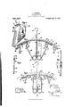
Referring to the drawings; Figure 1 shows in elevation an embodiment of theinvention in a suit hanger'; Fig. 2 is a similar view, but with the skirt or garment-sustainer only in full lines, and with the sustainer drawn in to inward limit of movement ,Fig. 3 is a section on the line TIL-III, Fig. 1, looking in the direction of the arrow, a portion of the suspension member being broken away to better show the guides; Fig. l is a section on the line IV-IV, Fig. 2, looking in the direction of the arrow; and Fig.5 is a view, with parts broken away, showing the use of the disclosed embodiment of the invention as a suit hanger. 3
The transverse guide or stifiening member 1, is provided with the inner guides 2 and the outer guides 3, herein shown as eyes. Medially, this member 1 has an opening l therethrough; Fig. 3, in which may loosely fit and slide the suspension convenience in hanging up the member 5 is formed portion of the suspension member 5 remote from the hook 6, is provided with an eye 7, designed to embrace the medial portion 8 of the one-piece garment-sustainer. Each way from the U-portion 8 the sustainer is of similar form. The first section therefrom is coil 9, being a yieldable distending means .or spring, having extension 10 terminatnig in an oppositely wound yielding means or spring coil 11, serving the additional purpose of convenient gripping means. From the coils 11 the sustainer extends to bends 12, from which the arm portions proj ect.
The arms have slide portions coacting with the eyes 2, 3, said slide portions comprising this suit. holder,
the rectilinear sections 13, the offset or bind I avoiding portions 14, and second rectilinear sections 15. The sections 15 of the slide portions of the arms terminate in return bends.
16, from which extend the outwardly and downwardly inclined portions 17 for engagement with the article to be sustained, as the waist-band of a skirt.
NAGELY, a citizen of the United States, residing at Toledo, Lucas county, Ohio, have invented a new member 5, For
with a hook 6. The
.a durable construction.
thumb of the right hand through the grip OperatioiifThe device is designed to be freely and easily voperable, yet effective in serving as a hanger. It is'simple in embodying a mlnimum number of elements, and of In thrusting the coil 11 frombehind, at the right of Fig. 1,
and moving. toward the suspension rod 5,
there" is flexibility permitting displacement as shown in dotted linesin'Fig. 1. When .the arm"; is drawn inward to its limit of movement, the suspension member is slightly flexed, and the opposite arm is tilted at its opposite end toflengage theupper, instead of the lowersideof eye 3. In practice, with the thumb in grip 11 as above stated, the
first and second lingers of the same hand may reach the opposite grip 11, and draw lnwarcl a suflicient distance to permit placing of waist-band of skirt 18 thereon, as
shown in Fig. 5, when the grips are released, permitting the arms to move outward through the distending action of coils 9 to automatically adjust the skirt hanger to the article thereon. Then the jacket portion of the suit may be hung on the member 1. With the grips 11 each drawn inward as shown in Fig. 2, thesuspension member 5 is drawn down a little, which may be noted by comparing the position of dotted bend 12 Fig. 1 with bends 12 Fig. 2, farther away from guide member and jacket holderrl. In order that the skirt may hang close up under the jacket holder, the article sustaining portions 17 of the arms are compactly disposed relatively to the slide portions of the arms. In order that the slideportions of the arms may also be a factor in this compact arrangement, they are largely rectilinear, thus of less downward extension than if curved. However, to permit of this rectilinear form and preclude binding, the intermediate offsets 14; are provided. An additional aid, insuring ease of operation, is the flexible connection of the arms to the sustainer intermediate portions through the yielding means of coils 11. Accordingly as the grips 11 are moved inward the coils 9 are wound up and exert a stronger distending action, while the coils 11v are unwound and in a measure ease up the action, not only in permitting the arms to take the directions freely through the eyes 23, but to some extent unwinding themselves in taking up the force exerted by springs 9. The suspension member 5 serves to give direction and approximate piece ances and adjusts itself position to the medial portion of the onegarmentsustainer, while the member 1, by means of its guides laterally stiffens the sustainer, compelling the travel of the arms in opposite directions.
The one=piece nature of the sustainer portion of the device, combined with its multiple yielding features 9, ll, taken in connection with the generalflexibility of engagement with members 5 and 6, results in the pro duction of a device which automatically balin the uses to which it may be put. The maximum range of travel shown for vice adapted to handling many sizes of skirts. That the continuous integral construction of the sustainer may be plainly apparent, this feature is shown alone in full lines inFig'. 2, while the other elements are shown in proper relation but dotted.
iV hat is claimed and it is desired to secure by Letters Patentis:
1. A suit hanger comprising a suspension device and a coat holder and skirt sustainer carried thereby, said skirt sustainer comprisiiig a one-piece element extending in the v direction of theholder and with skirt engagmg means near each end thereof, said one piece element having slidable coaction with the holder and embodying in itself integral distending means to normally throw the skirt engaging means outward.
2. A garment hanger embodying a suspension device, a transverse stiffening member, and a continuous one-piece garment sustainer having slidable coaction with the member and terminating in garment engaging means, said sustainer having its intermediate portion dis osed at an angle to the direction of the sti ening member and said intermediate portion comprising integral relatively yieldable sections to permit of the slidable coaction with the member 3. A suit hanger comprising a suspension device and a coat holder and skirt sustainer carried thereby, said skirt sustainer compris ing a one-piece element terminating in skirt the arms renders the de engaging means and having its integral inof the sustainer.
at. A garment hanger comprising a transverse stiffening member having openings forming a guide, and a continuous one-pieee garment sustainer terminating in garment engaging means, said onepiece sustainer having offsets near the garment engaging means, and having an intermediate yielding portion permitting the oifsets to slide through the guide member, whereby there is cooperative relation between the guide member and. sustainer permitting relative movement there between in mounting a garment on the sus tainer.
5. A suit hanger comprising a coat holder having guides, a skirt sustainer movable in the guides, and a suspension device for the sustainer having slidable engagement with the coat holder, said suspension device directly support-ing the sustainer, and said sustainer through the guides coat holder.
6. A garment hanger embodying a lateral stifi'ening member, and a one-piece garment sustainer having slidable coaction with the member, said sustainer having integral with itself arms terminating in garment engaging means, and having intermediate its arms a portion disposed at an angle to the member, which angularly disposed portion has integral spring connection with the arms to permit yielding for the slidable coaction with the member.
In testimony whereof I atlix my signature in the presence of two witnesses.
JOHN NAGELY. lVitnesses GEO. E. KiRK, C. H. RAUCII.
supporting the
Priority Applications (1)
| Application Number | Priority Date | Filing Date | Title |
|---|---|---|---|
| US43333408A US930407A (en) | 1908-05-18 | 1908-05-18 | Garment-hanger. |
Applications Claiming Priority (1)
| Application Number | Priority Date | Filing Date | Title |
|---|---|---|---|
| US43333408A US930407A (en) | 1908-05-18 | 1908-05-18 | Garment-hanger. |
Publications (1)
| Publication Number | Publication Date |
|---|---|
| US930407A true US930407A (en) | 1909-08-10 |
Family
ID=2998830
Family Applications (1)
| Application Number | Title | Priority Date | Filing Date |
|---|---|---|---|
| US43333408A Expired - Lifetime US930407A (en) | 1908-05-18 | 1908-05-18 | Garment-hanger. |
Country Status (1)
| Country | Link |
|---|---|
| US (1) | US930407A (en) |
Cited By (4)
| Publication number | Priority date | Publication date | Assignee | Title |
|---|---|---|---|---|
| US2467011A (en) * | 1947-05-28 | 1949-04-12 | William J Crosby | Stocking hanger |
| US2829810A (en) * | 1956-05-21 | 1958-04-08 | John M Wilson | Clothes hanger |
| US3737079A (en) * | 1971-09-10 | 1973-06-05 | W Bliss | Drying hanger assembly for woolen garments, and the like |
| US4600132A (en) * | 1985-04-24 | 1986-07-15 | John Thomas Batts, Inc. | Adjustable hanger |
-
1908
- 1908-05-18 US US43333408A patent/US930407A/en not_active Expired - Lifetime
Cited By (4)
| Publication number | Priority date | Publication date | Assignee | Title |
|---|---|---|---|---|
| US2467011A (en) * | 1947-05-28 | 1949-04-12 | William J Crosby | Stocking hanger |
| US2829810A (en) * | 1956-05-21 | 1958-04-08 | John M Wilson | Clothes hanger |
| US3737079A (en) * | 1971-09-10 | 1973-06-05 | W Bliss | Drying hanger assembly for woolen garments, and the like |
| US4600132A (en) * | 1985-04-24 | 1986-07-15 | John Thomas Batts, Inc. | Adjustable hanger |
Similar Documents
| Publication | Publication Date | Title |
|---|---|---|
| US3168970A (en) | Garment hanger having slip preventing means | |
| US930407A (en) | Garment-hanger. | |
| US1009522A (en) | Adjustable suit-hanger. | |
| US505578A (en) | Island | |
| US1563735A (en) | Coat-hanger attachment | |
| US586456A (en) | Coat-hanger | |
| US1705276A (en) | Safety garment hanger | |
| US2378578A (en) | Garment hanger | |
| US731597A (en) | Spring-clip for holding papers, &c. | |
| US9345355B2 (en) | Garment hanger attachment | |
| US915393A (en) | Garment-support. | |
| US424275A (en) | coles | |
| US1020608A (en) | Garment-hanger. | |
| US2513535A (en) | Trouser hanger | |
| US835481A (en) | Trousers-support. | |
| US2419621A (en) | Garment hanger | |
| US1574705A (en) | Wardrobe hanger | |
| US1015606A (en) | Garment-hanger. | |
| US1514987A (en) | Garment hanger | |
| US640616A (en) | Garment-hanger. | |
| US919501A (en) | Coat hanger or suspender. | |
| US689094A (en) | Clothes-holding device for suit-cases. | |
| US4160515A (en) | Clothes hanger | |
| GB2377631A (en) | Garment hanger | |
| US2068446A (en) | Clothes hanger |