US9294418B2 - 64B/66B codec for ethernet applications - Google Patents
64B/66B codec for ethernet applications Download PDFInfo
- Publication number
- US9294418B2 US9294418B2 US14/090,995 US201314090995A US9294418B2 US 9294418 B2 US9294418 B2 US 9294418B2 US 201314090995 A US201314090995 A US 201314090995A US 9294418 B2 US9294418 B2 US 9294418B2
- Authority
- US
- United States
- Prior art keywords
- codeword
- control block
- payload portion
- blocks
- block
- Prior art date
- Legal status (The legal status is an assumption and is not a legal conclusion. Google has not performed a legal analysis and makes no representation as to the accuracy of the status listed.)
- Active, expires
Links
Images


Classifications
-
- H—ELECTRICITY
- H04—ELECTRIC COMMUNICATION TECHNIQUE
- H04L—TRANSMISSION OF DIGITAL INFORMATION, e.g. TELEGRAPHIC COMMUNICATION
- H04L49/00—Packet switching elements
-
- H—ELECTRICITY
- H04—ELECTRIC COMMUNICATION TECHNIQUE
- H04L—TRANSMISSION OF DIGITAL INFORMATION, e.g. TELEGRAPHIC COMMUNICATION
- H04L12/00—Data switching networks
- H04L12/28—Data switching networks characterised by path configuration, e.g. LAN [Local Area Networks] or WAN [Wide Area Networks]
- H04L12/40—Bus networks
- H04L12/407—Bus networks with decentralised control
- H04L12/413—Bus networks with decentralised control with random access, e.g. carrier-sense multiple-access with collision detection (CSMA-CD)
-
- H—ELECTRICITY
- H04—ELECTRIC COMMUNICATION TECHNIQUE
- H04L—TRANSMISSION OF DIGITAL INFORMATION, e.g. TELEGRAPHIC COMMUNICATION
- H04L25/00—Baseband systems
- H04L25/38—Synchronous or start-stop systems, e.g. for Baudot code
- H04L25/40—Transmitting circuits; Receiving circuits
- H04L25/49—Transmitting circuits; Receiving circuits using code conversion at the transmitter; using predistortion; using insertion of idle bits for obtaining a desired frequency spectrum; using three or more amplitude levels ; Baseband coding techniques specific to data transmission systems
- H04L25/4906—Transmitting circuits; Receiving circuits using code conversion at the transmitter; using predistortion; using insertion of idle bits for obtaining a desired frequency spectrum; using three or more amplitude levels ; Baseband coding techniques specific to data transmission systems using binary codes
- H04L25/4908—Transmitting circuits; Receiving circuits using code conversion at the transmitter; using predistortion; using insertion of idle bits for obtaining a desired frequency spectrum; using three or more amplitude levels ; Baseband coding techniques specific to data transmission systems using binary codes using mBnB codes
-
- H—ELECTRICITY
- H04—ELECTRIC COMMUNICATION TECHNIQUE
- H04L—TRANSMISSION OF DIGITAL INFORMATION, e.g. TELEGRAPHIC COMMUNICATION
- H04L69/00—Network arrangements, protocols or services independent of the application payload and not provided for in the other groups of this subclass
- H04L69/04—Protocols for data compression, e.g. ROHC
Definitions
- a codec encodes a data stream or signal for transmission, storage, or encryption, and decodes the data for applications such as playback, editing or the like.
- a standardized 64b/66b codec as defined by the IEEE 802.3 group transforms a 64 bit data into a 66 bit codeword.
- the standard permits only a specific combination of data and control characters to be included in the codeword. Further, the standard imposes certain restrictions as to the location of a start control character within the codeword. Such restrictions tend to underutilize the payload bandwidth, thereby resulting in lower data transmission throughput.
- Data transmission in a fully flexible 64b/66b codec is increased by allowing any combination of data and control characters.
- the codeword structure of such a codec is significantly different than the codeword structure as defined by the IEEE standard, and is thus not compatible with the standard 100G Ethernet forward error correction schemes.
- a codec that includes an encoding circuit configured to transform input data into a codeword.
- the codeword includes a header portion and a payload portion, wherein the payload portion further includes a type control block and a plurality of blocks that are either control blocks or data blocks.
- the encoding circuit is configured to determine a location of a first control block of the plurality of blocks in the payload portion of the codeword based on the type control block and modify the first control block to create a reference block. Further, the encoding circuit inserts data blocks in the payload portion of the codeword subsequent to the location now corresponding to the reference block.
- Another embodiment provides a method that includes transforming input data into a codeword, wherein the codeword includes a header portion and a payload portion.
- the payload portion further includes a type control block and a plurality of blocks that are either control blocks or data blocks.
- the method determines a location of a first control block of the plurality of blocks in the payload portion of the codeword based on the type control block and modifies the first control block to create a reference block.
- the method eventually inserts data blocks in the payload portion of the codeword subsequent to the location now corresponding to the reference block.
- Another embodiment provide a non-transitory computer readable medium storing program instructions for causing a processor to execute operations for encoding.
- the operations include transforming input data into a codeword, wherein the codeword includes a header portion and a payload portion.
- the payload portion further includes a type control block and a plurality of blocks that are either control blocks or data blocks.
- the operation further determines a location of a first control block of the plurality of blocks in the payload portion of the codeword based on the type control block and modifies the first control block to create a reference block.
- the operation eventually inserts data blocks in the payload portion of the codeword subsequent to the location now corresponding to the reference block.
- FIG. 1 shows an encoding-decoding communication system
- FIG. 2 shows a codeword structure for a standardized 64b/66b codec
- FIG. 3 shows a modified codeword structure for a 64b/66b codec according to an embodiment of the disclosure
- FIG. 4 depicts a flowchart outlining an encoding process 400 according to an embodiment of the disclosure.
- FIG. 5 depicts a flowchart outlining a decoding process 500 according to an embodiment of the disclosure.
- FIG. 1 shows a communication system 100 according to an embodiment.
- the system includes a source 101 that transmits data to a destination 107 .
- the data 102 , transmitted by the source 101 is first encoded by an encoder 104 .
- the encoder 104 is configured to take as input, the data 102 to be transmitted to the destination 107 and convert the input data to a codeword 103 that includes a header 103 a , and a payload 103 b .
- the encoder 104 is a 64b/66b codec (coder-decoder).
- the 64b/66b codec is configured to transform a 64 bit input data, to a 66 bit codeword. Specific details regarding the codeword structure of the 64b/66b codec are discussed below with respect reference to FIG. 2 .
- the codeword 103 may undergo other forms of encoding and data processing steps such as physical layer coding, forward error correction, data scrambling or the like, prior to being sent to the communication network 105 .
- the communication network 105 may be a wide area network, local area network or the like.
- the codeword 103 traverses the network 105 , and upon reaching the destination 107 , a decoder 106 (included at the destination) extracts the data from the received codeword.
- the encoder 104 and the decoder 106 of the communication system 100 , may be a 64b/66b codec.
- FIG. 2 depicts a codeword structure of a 64b/66b codec as standardized by the IEEE 802.3 group.
- input data 201 is represented as a codeword that includes a sequence of eight characters.
- the characters include data characters (represented as ‘D’), control characters (represented as ‘C’), a start character (represented as ‘S’) and a termination character (represented as ‘T’).
- the start character ‘S’ indicates the beginning of data characters in a codeword and the termination character denotes the end of data characters that are included in the codeword.
- Control characters are framing characters that identify framing boundaries between groups of data characters.
- the input data can be represented as a data codeword 211 that includes only data characters, or can be one of a control codeword 212 - 222 , that includes a combination of data and control characters.
- the standard governs that the control codewords are permitted to include only specific combination of the data and control characters. Further, the standard also poses certain restrictions as to the location of certain control characters within the codeword. For example, as shown in codeword 213 , a start character is permitted to appear only at the beginning position of the codeword.
- the physical codeword structure of the 64b/66b codec corresponding to a particular codeword is represented in 203 .
- the structure of each codeword is sixty six bits long and includes a header portion 203 a , and a payload portion 203 b .
- the header portion 203 a is two bits long and the payload portion 203 b is sixty four bits long.
- the payload portion is segmented to carry a plurality of data blocks and control blocks. Each data block is eight bits long and each control block is seven bits long.
- the header portion 203 a is defined by either using the bit string ‘01’ or ‘10’.
- the header ‘01’ indicates that the payload portion of the codeword includes only data blocks.
- the codeword structure 241 (corresponding to the data codeword 211 ) includes the header ‘01’, and eight data blocks represented as D 0 -D 7 .
- the structure of the codewords 242 - 252 include an eight-bit type control block 205 , that occupies the first byte in the payload portion of the codeword.
- the hexadecimal value of the type block determines the positioning of data blocks and control blocks in the payload portion of the codeword. For example, considering the codeword structure 243 (corresponding to the control codeword 213 ), the hexadecimal value of ‘0x78’ in the type block field indicates that the payload portion of the codeword 243 includes seven data blocks, D 1 -D 7 . This corresponds to the control codeword 213 , which denotes a start character followed by seven data characters. Similarly, in the codeword structure 242 , the hexadecimal value of ‘0x1E’ in the type block field indicates that the remainder of the payload portion includes only control blocks that are represented as C 0 -C 7 .
- the standard permits the start character (S) to appear only at the beginning of the codeword. This requirement results in an inefficient use of the payload bandwidth.
- the control codeword 215 begins with a termination character (T 0 ), followed by seven control characters (C 1 -C 7 ).
- the corresponding codeword structure 245 includes a predetermined hexadecimal value of ‘0x87’ in the type block field. This particular hexadecimal value indicates that the last data block was transmitted in the previous codeword, and that the current codeword includes only control blocks. Since the start character is allowed to appear only at the first position in a codeword, no data blocks can be transmitted in the present codeword.
- the codeword 245 also has a total of seven unused bits represented by 209 .
- the control codewords 216 - 221 represent a termination character that appears in the control codeword.
- the corresponding codeword structures 246 - 251 each include a specific hexadecimal value in the type block field, which indicates a location as to where control blocks begin in the payload portion of the codeword. Similar to the codeword structure of 245 , the codeword structures 246 - 251 (corresponding to the codewords 216 - 221 ) include up to six control blocks in the payload portion of the codeword, thereby resulting in inefficient use of payload bandwidth.
- a modified codeword structure for the 64b/66b codec configured to increase data throughput is first described. Further, a method of encoding and decoding using the modified 64b/66b codeword structure is described.
- FIG. 3 shows a modified codeword structure of a 64b/66b codec according to an embodiment of the present disclosure.
- block 301 represents the control codewords 315 - 322 , that correspond to the control codewords 215 - 222 of FIG. 2 .
- the codeword structure 345 - 352 corresponding to each control codeword 315 - 322 is depicted in 303 .
- each codeword structure in FIG. 3 includes a header portion 303 a that can be two bits long and a payload portion 303 b that can have a length of sixty four bits.
- the payload portion of the codeword structure includes an eight bit type block 305 that determines the format of the data blocks and control blocks in the payload portion of the codeword.
- the modified control codewords 301 permit a start character (S) to appear within the codeword sequence of eight characters.
- the control codeword 315 includes a start character (S 1 ) inserted after the termination character (T 0 ).
- data characters D 2 -D 7 are permitted to be transmitted in the present codeword.
- six data characters D 2 -D 7 may be transmitted in the present codeword, as opposed to transmitting seven control characters C 1 -C 7 as shown in the codeword 215 in FIG. 2 .
- the modified 64b/66b codec uses the type block field to determine the location of the first control block in the payload portion of the codeword structure.
- the type block includes a hexadecimal value ‘0x87’ that is similar to the block type field of FIG. 2 . Based on this value, the codec can determine the location (in the payload portion of the codeword) of the first control block 362 , which would be included in the standardized codeword structure.
- an encoding circuit included in the codec can be configured to change the most significant bit of the first control block from bit ‘0’ to bit ‘1’.
- the IEEE standard permits the use of only two control blocks, the idle control block that is encoded by the seven bit string ‘0000000’, and an error control block that is encoded by the seven bit string ‘0011110’. Both, the idle control block and the error control block have a bit ‘0’ in the most significant bit position.
- the codec modifies the most significant bit and couples it with any unused bits to create a reference block 361 . Note that as stated previously with reference to block 209 in FIG. 2 , that unused bits result from using eight bit long data blocks and seven bit long control blocks and having a requirement of aligning the control and data blocks on an 8-byte boundary.
- control codewords 316 - 321 can insert up to five data blocks in the payload portion of the codeword, instead of assigning the corresponding payload bandwidth to control blocks.
- the bandwidth of the payload portion can be used in an optimal manner, while ensuring that the modified codeword structure uses the same hexadecimal type block values as set by the 802.3 standard.
- the Quantum codec modifies the codewords to include a start character to immediately follow a termination character. Both, the start and termination characters are encoded by a type control block that indicates the ordering of the blocks in the payload portion of the codeword. By modifying the most significant bit of the first control block, and thereafter creating a reference block, the Quantum codec permits an increase data throughput. Further, the Quantum codec is compatible with the 100 Gigabit Ethernet standard and transparent to physical layer coding schemes, forward error correction control schemes and data scrambling systems.
- the Quantum codec completely reduces the number of wasted data bytes in the payload portion of the codeword. For example, considering a payload of 64 bytes, the standard 64b/66b codec, results in wasting six data bytes (consuming a total of seventy two bytes including the start and terminate characters) and achieves a total overhead of 12.5%. In contrast, the Quantum codec does not waste any data bytes and consumes a total of sixty-six bytes including the start and terminate characters. Thus, the quantum codec achieves a total overhead of 3.1%.
- the created reference block in the payload portion of the codeword is eight bits long. As stated above, higher data throughput is achieved by only incorporating the modified, most significant bit of the first control block. Thus, the remaining seven bits of the reference block are not used. This unused capacity can be used, for example, to create special control characters for proprietary applications. Further, a hamming distance between the codewords can be increased, by using all the eight bits of the reference block to improve error robustness in high bit-error prone applications. Specifically, the Hamming distance between two strings of equal length is the number of positions at which the corresponding symbols are different.
- the two eight bit strings ‘01010101’ and ‘01011001’ have a Hamming distance of 2.
- codewords can be created such that a larger Hamming distance between codewords is achieved, thereby increasing error robustness.
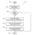
- FIG. 4 shows a flowchart outlining a process 400 of encoding a codeword to increase data block transmission according to an embodiment of the disclosure. The process starts at S 410 , and proceeds to S 420 .
- input data is transformed into a codeword that includes a payload portion and a header portion. The process then moves to S 430 .
- a query is made to determine the type of header included in the header portion of the codeword. Specifically, a query is made to check if the header is of a predetermined type, which indicates the presence of control blocks in a payload portion of the codeword. If the response to the query is affirmative, the process moves to S 440 . If the response to the query is negative, the process moves to S 470 and terminates. Note that if the payload portion of the codeword includes only data blocks, no further increase in data transmission can be obtained.
- the codec determines that the payload portion of the codeword includes only data blocks, whereas if the 2-bit header is ‘10’, the codec determines the presence of control blocks in the payload portion of the codeword.
- the identified first control block from S 440 is modified to create a reference block. Specifically, a most significant bit of the first control block is modified and paired with unused bits in the payload portion to create a reference block.
- the encoder inserts data blocks, subsequent to the reference block created in S 450 .
- consecutive code words can be configured to transmit data blocks, as opposed to transmitting a series on control blocks between data transmission.
- the bandwidth of a codeword can be used in an optimal manner.
- FIG. 5 shows a flowchart outlining a process 500 of decoding a codeword according to an embodiment of the disclosure. The process starts at S 510 , and proceeds to S 520 .
- the header portion of the codeword is first processed to determine the type of header.
- a query is made to check if the processed header of S 520 is of a predetermined type, which indicates that data blocks were inserted in the payload portion of the codeword in place of control blocks. If the response to the query is affirmative, the process moves to S 550 . If the response to the query in S 530 is negative, the process moves to S 540 . In an example, if a 2-bit header is ‘01’, the decoder determines that the payload portion of the codeword includes only data blocks and proceeds to S 540 . On the other hand, if the 2-bit header is ‘10’, the decoder determines that the payload portion of the codeword was modified. Specifically, control blocks in the codeword were replaced with additional data blocks in order to increase data block throughput.
- the decoder decodes the data blocks from the payload portion of the codeword and then the process moves to S 560 and terminates.
- the decoder processes a type control block and a reference block included in the payload portion of the codeword to determine the positions of data blocks in the codeword. Upon locating the positions of the data blocks, the decoder merely extracts the data blocks and terminates the process in S 560 .
Abstract
Description
Claims (16)
Priority Applications (1)
| Application Number | Priority Date | Filing Date | Title |
|---|---|---|---|
| US14/090,995 US9294418B2 (en) | 2012-11-28 | 2013-11-26 | 64B/66B codec for ethernet applications |
Applications Claiming Priority (2)
| Application Number | Priority Date | Filing Date | Title |
|---|---|---|---|
| US201261730727P | 2012-11-28 | 2012-11-28 | |
| US14/090,995 US9294418B2 (en) | 2012-11-28 | 2013-11-26 | 64B/66B codec for ethernet applications |
Publications (2)
| Publication Number | Publication Date |
|---|---|
| US20140146835A1 US20140146835A1 (en) | 2014-05-29 |
| US9294418B2 true US9294418B2 (en) | 2016-03-22 |
Family
ID=50773267
Family Applications (1)
| Application Number | Title | Priority Date | Filing Date |
|---|---|---|---|
| US14/090,995 Active 2034-01-28 US9294418B2 (en) | 2012-11-28 | 2013-11-26 | 64B/66B codec for ethernet applications |
Country Status (1)
| Country | Link |
|---|---|
| US (1) | US9294418B2 (en) |
Cited By (1)
| Publication number | Priority date | Publication date | Assignee | Title |
|---|---|---|---|---|
| WO2020029893A1 (en) * | 2018-08-07 | 2020-02-13 | 华为技术有限公司 | Method for receiving code block stream, method for sending code block stream and communication device |
Families Citing this family (2)
| Publication number | Priority date | Publication date | Assignee | Title |
|---|---|---|---|---|
| US9154454B1 (en) * | 2013-03-14 | 2015-10-06 | Cisco Technology, Inc. | Fabric link physical coding sublayer packing scheme |
| CN107566075B (en) | 2016-07-01 | 2019-10-25 | 华为技术有限公司 | A kind of method, apparatus and network system sending and receiving business |
Citations (5)
| Publication number | Priority date | Publication date | Assignee | Title |
|---|---|---|---|---|
| US20050047433A1 (en) * | 2003-06-17 | 2005-03-03 | Dmitri Rizer | Physical coding sublayer transcoding |
| US20070101241A1 (en) * | 2005-10-17 | 2007-05-03 | Enigma Semiconductor, Inc. | 64b/66b Coding apparatus and method |
| US7639687B1 (en) * | 2004-12-30 | 2009-12-29 | Marvell International Ltd. | Encoding scheme with arbitrary control symbol placement |
| US7782805B1 (en) * | 2005-02-08 | 2010-08-24 | Med Belhadj | High speed packet interface and method |
| US20130235886A1 (en) * | 2012-03-12 | 2013-09-12 | Broadcom Corporation | Reduced Complexity Transcoding |
-
2013
- 2013-11-26 US US14/090,995 patent/US9294418B2/en active Active
Patent Citations (6)
| Publication number | Priority date | Publication date | Assignee | Title |
|---|---|---|---|---|
| US20050047433A1 (en) * | 2003-06-17 | 2005-03-03 | Dmitri Rizer | Physical coding sublayer transcoding |
| US7639687B1 (en) * | 2004-12-30 | 2009-12-29 | Marvell International Ltd. | Encoding scheme with arbitrary control symbol placement |
| US7782805B1 (en) * | 2005-02-08 | 2010-08-24 | Med Belhadj | High speed packet interface and method |
| US20070101241A1 (en) * | 2005-10-17 | 2007-05-03 | Enigma Semiconductor, Inc. | 64b/66b Coding apparatus and method |
| US7487426B2 (en) | 2005-10-17 | 2009-02-03 | Enigma Semiconductor, Inc. | 64b/66b coding apparatus and method |
| US20130235886A1 (en) * | 2012-03-12 | 2013-09-12 | Broadcom Corporation | Reduced Complexity Transcoding |
Cited By (3)
| Publication number | Priority date | Publication date | Assignee | Title |
|---|---|---|---|---|
| WO2020029893A1 (en) * | 2018-08-07 | 2020-02-13 | 华为技术有限公司 | Method for receiving code block stream, method for sending code block stream and communication device |
| JP2021533656A (en) * | 2018-08-07 | 2021-12-02 | ホアウェイ・テクノロジーズ・カンパニー・リミテッド | How to receive a code blockstream, how to send a codeblock stream, and communication equipment |
| US11902403B2 (en) | 2018-08-07 | 2024-02-13 | Huawei Technologies Co., Ltd. | Method for receiving code block stream, method for sending code block stream, and communications apparatus |
Also Published As
| Publication number | Publication date |
|---|---|
| US20140146835A1 (en) | 2014-05-29 |
Similar Documents
| Publication | Publication Date | Title |
|---|---|---|
| EP2966823B1 (en) | Encoding and decoding methods and apparatuses of ethernet physical layer | |
| CN104426629A (en) | Physical layer coding and decoding methods and devices | |
| US10608781B2 (en) | Applying forward error correction in 66b systems | |
| CN1154285C (en) | Flexible method of error protection in communications systems | |
| US8898550B2 (en) | Encoding of data for transmission | |
| US6930621B2 (en) | Method to overlay a secondary communication channel onto an encoded primary communication channel | |
| US9294418B2 (en) | 64B/66B codec for ethernet applications | |
| CN109698732B (en) | Method and device for transmitting data | |
| JP4751888B2 (en) | Encoding method and encoding apparatus for E-DCH dedicated physical control channel | |
| WO2016082434A1 (en) | Serial data sending and receiving methods and apparatuses, and storage medium | |
| MX2014013560A (en) | Apparatus and method of transmitting and receiving packet in a broadcasting and communication system. | |
| CN101854224A (en) | Error correcting coding method, device and system, and forwarding control method and device | |
| US6985726B2 (en) | Method of blind transport format detection | |
| CN102195750B (en) | Data transfer device and data transfer system | |
| US10355823B2 (en) | System and method for block-coding transcoding | |
| WO2018040824A1 (en) | Data encoding method, data decoding method, devices, and data storage medium | |
| KR20090038387A (en) | Method and system for transmission of digital audio in spdif format to one or more receivers | |
| US8705633B2 (en) | Method and apparatus for transporting an 8B/10B coded video stream across a 64B/66B coded link | |
| WO2018133415A1 (en) | Method and device for coding and decoding data of physical coding sublayer and storage medium | |
| TW202320493A (en) | Transition encoder and method for transition encoding with flexible word-size | |
| US20100209102A1 (en) | Encoding fibre channel over ethernet transport | |
| CN103369311A (en) | Method for preventing conflict of initial code | |
| US7251767B2 (en) | Method for correcting errors in a packet-oriented data transmission | |
| WO2022257721A1 (en) | Encoding method, decoding method, and optical module | |
| WO2023231429A1 (en) | Data transmission method, source end device, sink end device and storage medium |
Legal Events
| Date | Code | Title | Description |
|---|---|---|---|
| AS | Assignment |
Owner name: MARVELL INTERNATIONAL LTD., BERMUDA Free format text: ASSIGNMENT OF ASSIGNORS INTEREST;ASSIGNOR:MARVELL TECHNOLOGY DENMARK (MTDK);REEL/FRAME:035397/0678 Effective date: 20131126 Owner name: MARVELL TECHNOLOGY DENMARK (MTDK), DENMARK Free format text: ASSIGNMENT OF ASSIGNORS INTEREST;ASSIGNORS:HOYER, CLAUS F.;SCHRODER, JACOB J.;REEL/FRAME:035397/0645 Effective date: 20131126 |
|
| STCF | Information on status: patent grant |
Free format text: PATENTED CASE |
|
| MAFP | Maintenance fee payment |
Free format text: PAYMENT OF MAINTENANCE FEE, 4TH YEAR, LARGE ENTITY (ORIGINAL EVENT CODE: M1551); ENTITY STATUS OF PATENT OWNER: LARGE ENTITY Year of fee payment: 4 |
|
| AS | Assignment |
Owner name: CAVIUM INTERNATIONAL, CAYMAN ISLANDS Free format text: ASSIGNMENT OF ASSIGNORS INTEREST;ASSIGNOR:MARVELL INTERNATIONAL LTD.;REEL/FRAME:052918/0001 Effective date: 20191231 |
|
| AS | Assignment |
Owner name: MARVELL ASIA PTE, LTD., SINGAPORE Free format text: ASSIGNMENT OF ASSIGNORS INTEREST;ASSIGNOR:CAVIUM INTERNATIONAL;REEL/FRAME:053475/0001 Effective date: 20191231 |
|
| MAFP | Maintenance fee payment |
Free format text: PAYMENT OF MAINTENANCE FEE, 8TH YEAR, LARGE ENTITY (ORIGINAL EVENT CODE: M1552); ENTITY STATUS OF PATENT OWNER: LARGE ENTITY Year of fee payment: 8 |