US9289093B2 - Brewing assembly and beverages production machine comprising said assembly - Google Patents
Brewing assembly and beverages production machine comprising said assembly Download PDFInfo
- Publication number
- US9289093B2 US9289093B2 US13/981,400 US201213981400A US9289093B2 US 9289093 B2 US9289093 B2 US 9289093B2 US 201213981400 A US201213981400 A US 201213981400A US 9289093 B2 US9289093 B2 US 9289093B2
- Authority
- US
- United States
- Prior art keywords
- brewing chamber
- support structure
- brewing
- chamber
- boiler
- Prior art date
- Legal status (The legal status is an assumption and is not a legal conclusion. Google has not performed a legal analysis and makes no representation as to the accuracy of the status listed.)
- Expired - Fee Related, expires
Links
- 235000013361 beverage Nutrition 0.000 title claims description 43
- 238000004519 manufacturing process Methods 0.000 title claims description 14
- 239000008236 heating water Substances 0.000 claims abstract 5
- XLYOFNOQVPJJNP-UHFFFAOYSA-N water Substances O XLYOFNOQVPJJNP-UHFFFAOYSA-N 0.000 claims description 46
- 230000008878 coupling Effects 0.000 claims description 17
- 238000010168 coupling process Methods 0.000 claims description 17
- 238000005859 coupling reaction Methods 0.000 claims description 17
- 238000013519 translation Methods 0.000 claims description 12
- 238000003780 insertion Methods 0.000 claims description 5
- 230000037431 insertion Effects 0.000 claims description 5
- 235000012171 hot beverage Nutrition 0.000 claims description 4
- 239000012530 fluid Substances 0.000 claims description 3
- 235000016213 coffee Nutrition 0.000 description 21
- 235000013353 coffee beverage Nutrition 0.000 description 21
- 230000002441 reversible effect Effects 0.000 description 7
- 238000004140 cleaning Methods 0.000 description 5
- 235000013305 food Nutrition 0.000 description 4
- 230000007246 mechanism Effects 0.000 description 4
- 239000000843 powder Substances 0.000 description 4
- 238000005406 washing Methods 0.000 description 4
- 239000002775 capsule Substances 0.000 description 3
- 239000004020 conductor Substances 0.000 description 3
- 235000015114 espresso Nutrition 0.000 description 3
- 238000010438 heat treatment Methods 0.000 description 3
- 238000006243 chemical reaction Methods 0.000 description 2
- 230000006835 compression Effects 0.000 description 2
- 238000007906 compression Methods 0.000 description 2
- 230000001419 dependent effect Effects 0.000 description 2
- 239000004615 ingredient Substances 0.000 description 2
- 239000000463 material Substances 0.000 description 2
- 238000000034 method Methods 0.000 description 2
- 238000013459 approach Methods 0.000 description 1
- 235000019568 aromas Nutrition 0.000 description 1
- 230000000712 assembly Effects 0.000 description 1
- 238000000429 assembly Methods 0.000 description 1
- 230000003670 easy-to-clean Effects 0.000 description 1
- 238000000605 extraction Methods 0.000 description 1
- 230000001050 lubricating effect Effects 0.000 description 1
- 238000012423 maintenance Methods 0.000 description 1
- 230000000737 periodic effect Effects 0.000 description 1
- 238000002360 preparation method Methods 0.000 description 1
- 238000012546 transfer Methods 0.000 description 1
Images


Classifications
-
- A—HUMAN NECESSITIES
- A47—FURNITURE; DOMESTIC ARTICLES OR APPLIANCES; COFFEE MILLS; SPICE MILLS; SUCTION CLEANERS IN GENERAL
- A47J—KITCHEN EQUIPMENT; COFFEE MILLS; SPICE MILLS; APPARATUS FOR MAKING BEVERAGES
- A47J31/00—Apparatus for making beverages
- A47J31/24—Coffee-making apparatus in which hot water is passed through the filter under pressure, i.e. in which the coffee grounds are extracted under pressure
- A47J31/34—Coffee-making apparatus in which hot water is passed through the filter under pressure, i.e. in which the coffee grounds are extracted under pressure with hot water under liquid pressure
- A47J31/36—Coffee-making apparatus in which hot water is passed through the filter under pressure, i.e. in which the coffee grounds are extracted under pressure with hot water under liquid pressure with mechanical pressure-producing means
- A47J31/3604—Coffee-making apparatus in which hot water is passed through the filter under pressure, i.e. in which the coffee grounds are extracted under pressure with hot water under liquid pressure with mechanical pressure-producing means with a mechanism arranged to move the brewing chamber between loading, infusing and ejecting stations
- A47J31/3609—Loose coffee being employed
- A47J31/3614—Means to perform transfer from a loading position to an infusing position
-
- A—HUMAN NECESSITIES
- A47—FURNITURE; DOMESTIC ARTICLES OR APPLIANCES; COFFEE MILLS; SPICE MILLS; SUCTION CLEANERS IN GENERAL
- A47J—KITCHEN EQUIPMENT; COFFEE MILLS; SPICE MILLS; APPARATUS FOR MAKING BEVERAGES
- A47J31/00—Apparatus for making beverages
- A47J31/24—Coffee-making apparatus in which hot water is passed through the filter under pressure, i.e. in which the coffee grounds are extracted under pressure
- A47J31/34—Coffee-making apparatus in which hot water is passed through the filter under pressure, i.e. in which the coffee grounds are extracted under pressure with hot water under liquid pressure
- A47J31/36—Coffee-making apparatus in which hot water is passed through the filter under pressure, i.e. in which the coffee grounds are extracted under pressure with hot water under liquid pressure with mechanical pressure-producing means
- A47J31/3604—Coffee-making apparatus in which hot water is passed through the filter under pressure, i.e. in which the coffee grounds are extracted under pressure with hot water under liquid pressure with mechanical pressure-producing means with a mechanism arranged to move the brewing chamber between loading, infusing and ejecting stations
- A47J31/3609—Loose coffee being employed
- A47J31/3619—Means to remove coffee after brewing
-
- A—HUMAN NECESSITIES
- A47—FURNITURE; DOMESTIC ARTICLES OR APPLIANCES; COFFEE MILLS; SPICE MILLS; SUCTION CLEANERS IN GENERAL
- A47J—KITCHEN EQUIPMENT; COFFEE MILLS; SPICE MILLS; APPARATUS FOR MAKING BEVERAGES
- A47J31/00—Apparatus for making beverages
- A47J31/24—Coffee-making apparatus in which hot water is passed through the filter under pressure, i.e. in which the coffee grounds are extracted under pressure
- A47J31/34—Coffee-making apparatus in which hot water is passed through the filter under pressure, i.e. in which the coffee grounds are extracted under pressure with hot water under liquid pressure
- A47J31/36—Coffee-making apparatus in which hot water is passed through the filter under pressure, i.e. in which the coffee grounds are extracted under pressure with hot water under liquid pressure with mechanical pressure-producing means
- A47J31/3604—Coffee-making apparatus in which hot water is passed through the filter under pressure, i.e. in which the coffee grounds are extracted under pressure with hot water under liquid pressure with mechanical pressure-producing means with a mechanism arranged to move the brewing chamber between loading, infusing and ejecting stations
- A47J31/3623—Cartridges being employed
- A47J31/3633—Means to perform transfer from a loading position to an infusing position
-
- A—HUMAN NECESSITIES
- A47—FURNITURE; DOMESTIC ARTICLES OR APPLIANCES; COFFEE MILLS; SPICE MILLS; SUCTION CLEANERS IN GENERAL
- A47J—KITCHEN EQUIPMENT; COFFEE MILLS; SPICE MILLS; APPARATUS FOR MAKING BEVERAGES
- A47J31/00—Apparatus for making beverages
- A47J31/44—Parts or details or accessories of beverage-making apparatus
- A47J31/4403—Constructional details
Definitions
- the present invention relates to machines for producing hot beverages, for example coffee machines.
- Automatic or semiautomatic beverage machines for domestic or commercial use have a brewing assembly comprising two mutually mobile portions which open to receive a food product, for example coffee powder (loose or packaged in capsules or pods), and to adopt a closed position in which pressurised hot water is fed through the brewing chamber in order to extract aromas from the food product loaded therein and to produce the beverage.
- a food product for example coffee powder (loose or packaged in capsules or pods)
- pressurised hot water is fed through the brewing chamber in order to extract aromas from the food product loaded therein and to produce the beverage.
- These machines also have a boiler for production of the hot water, fed by a pump in order to achieve suitable brewing pressures.
- EP 0931491 discloses a brewing assembly for a coffee machine of the type mentioned above, in which the boiler is formed in one piece with one of the portions of the brewing chamber so as to reduce thermal losses.
- brewing assemblies of this type in particular which are intended for the production of espresso coffee, the water is fed at a relatively high pressure of approximately 8-15 bar. These high pressures generate high stresses in the brewing chamber and it is therefore necessary to provide a suitable support structure onto which the stresses can be unloaded during the brewing phase.
- the invention provides a brewing assembly comprising a support structure and a brewing chamber comprising at least two mutually mobile portions for closing and opening a brewing volume, which brewing assembly is particularly efficient in terms of energy savings, mechanical robustness.
- the invention basically relates to a brewing assembly of the above-mentioned type for the production of hot beverages via extraction with pressurised hot water of a product loaded in a brewing chamber, in which brewing assembly: the support structure of the brewing chamber is subdivided into a first part which is fastened to a first portion of the brewing chamber, and a second part which is fastened to a second portion of the brewing chamber; the first part and the second part of the support structure can be mutually coupled and uncoupled; the first portion of the brewing chamber and the second portion of the brewing chamber are mobile to adopt an open position, and a closed position of the brewing chamber when the first part and the second part of the support structure are coupled; and the boiler is rigidly connected to one of said first and second parts of the support structure and to one of said first and second portions of the brewing chamber.
- This second part of the support structure and the respective second portion of the brewing chamber are housed in a substantially rigid manner in a machine housing, whereas the first part of the support structure and the first part of the brewing chamber can be taken out from the machine housing.
- the boiler is therefore in thermal contact with the second part of the support structure of the brewing chamber and with the second part of the brewing chamber, in such a way that it is possible to maintain the temperature of at least one zone of the brewing chamber and therefore to supply a hotter beverage.
- the two parts of the support structure can be fastened and unfastened, making it possible to leave the boiler rigidly in the machine together with the second part of the support structure, whilst the first part of the support structure can be taken out with the respective first portion of the brewing chamber so as to be easily washed, or else so as to carry out other maintenance, replacement or component repair procedures.
- the boiler surrounds a duct supplying the beverage from the brewing chamber. In further embodiments of the invention the boiler surrounds a duct feeding water from the boiler to the brewing chamber. In both cases there is a thermal advantage and in the first case there is also the advantage of a higher temperature of the beverage supplied.
- the boiler is preferably a boiler of the instantaneous type.
- the heating resistor and the water duct are preferably housed in a module which is made of thermally conductive material and forms the body of the boiler.
- the resistor and the water duct preferably each form one or more coils inside said module.
- the coil or coils formed by the electric resistor surround the beverage supply duct.
- the module forming the body of the boiler is advantageously hollow so as to allow the beverage duct to pass from the brewing chamber to a supplier assembly, or else to allow hot water to pass from the boiler to the brewing chamber.
- the second part of the support structure houses the boiler, which is advantageously in thermal contact with the material forming the second part of the support structure, through which material passes the duct supplying the beverage from the brewing chamber or the duct feeding water from the boiler to the brewing chamber.
- a conductive heat exchange circuit is thus formed which comprises the wall of the beverage supply duct (or the water feed duct), the second part of the support structure and the body of the boiler.
- the first part of the support structure and the second part of the support structure can be coupled together via reciprocal male and female coupling members.
- the reciprocal coupling members may comprise at least one pair of pins or projections and a pair of guides, into which said pins or projections are inserted when the first part of the support structure and the second part of the support structure are mutually coupled.
- the pins or projections are formed in one piece with one of said first and second parts of the support structure and the guides are formed in one piece with the other of said first and second parts of the support structure.
- the pins or projections are formed in one piece with the first part, which can be taken out from the support structure, and the guides are formed in one piece with the second, fixed part of the support structure. A reverse arrangement is not excluded.
- a mutual locking member of the two parts of the support structure may be provided, for example a resilient latching system comprising a pin and a latching seat.
- the pin can be carried by the first part of the support structure and, for example, can be connected to an unlocking lever.
- the lever can be arranged between two sides of the first part of the support structure.
- a single lever may be provided which is articulated to the part of the support structure which can be taken out and is equipped with two opposed pins which cooperate with two opposed latching seats formed in the fixed part of the support structure.
- the two parts of the support structure each comprise two opposed sides.
- the first portion of the brewing chamber may advantageously be arranged between the sides of the first part of the support structure.
- One of said sides may be equipped with a hole allowing a drive shaft to pass through, which drive shaft controls the opening and closing movement of the brewing chamber.
- the kinematic mechanisms for the transfer of motion from the drive shaft to the brewing chamber are advantageously arranged between the two sides of the first part of the support structure.
- the lever for unlocking the two parts of the support structure may also be articulated between the two sides of the first part of the support structure.
- the boiler may advantageously be arranged between the two opposed sides of the second part of the support structure.
- projections are formed on the sides of the first part of the support structure and insert into guides formed in the sides of the second part of the support to mechanically couple the two parts of the support structure and to form a closed frame which internally houses the brewing chamber.
- the first portion of the brewing chamber comprises a coupling to an actuator, for example an electric motor, for opening and closing which moves said first portion of the brewing chamber relative to the support structure.
- the first part of the support structure defines a loading position of the brewing chamber, in which the first portion of the brewing chamber is arranged beneath a loading opening for the product to be loaded in the brewing chamber.
- the first part of the support structure comprises guides for sliding the first portion of the brewing chamber in order to guide the approaching movement of the first portion of the brewing chamber towards the second portion of the brewing chamber fastened to the second part of the support structure.
- the first portion of the brewing chamber comprises a substantially cylindrical, hollow body and a wall for closing said substantially cylindrical body; and the second portion of the brewing chamber comprises a piston for closing said substantially cylindrical body, said piston and said closing wall being mutually opposed when the brewing chamber is closed.
- the closing wall of the brewing chamber may comprise through-holes for the feed of pressurised water and the piston may comprise holes to allow the passing through of the beverage extracted from the product loaded in the brewing chamber.
- the duct supplying the beverage from the brewing chamber is preferably in fluid connection with said piston and can extend through a shank of the piston itself, formed in one piece with the second part of the support structure.
- a reverse arrangement of the feed of pressurised hot water to the brewing chamber and of supply of the beverage from the brewing chamber may be provided.
- the piston forming part of the second portion of the brewing chamber may be removable from the second part of the support structure in order to be washed or replaced.
- the piston can be coupled, for example, to a bayonet system on its shank which, conversely, can remain rigidly coupled to the support structure.
- the first portion of the brewing chamber moves in rotation and in translation in order to open and close the brewing chamber.
- the connector can advantageously be connected to the hot water feed duct via a movement in translation of the first portion of the brewing chamber, as a result of which said first portion of the brewing chamber approaches the second portion of the brewing chamber.
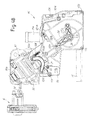
- FIGS. 2A and 2B are side views, partly in section, of the brewing assembly inserted into the housing of the machine and with the brewing chamber open;
- FIGS. 3A and 3B are side views, partly in section, similar to FIGS. 2A and 2B in a closing phase of the brewing chamber;
- FIGS. 4A and 4B are views similar to those of FIGS. 3A and 3B in a rinsing phase of the brewing chamber;
- FIGS. 5A and 5B are views similar to those of FIGS. 3A and 3B in a brewing position with a different volume of the brewing chamber;
- FIGS. 6A-6G show a sequence, in 3-D, of the mutual unfastening procedures of the two parts of the structure of the brewing assembly
- FIG. 7 is a front view of the brewing assembly inserted into its seat in the machine
- FIG. 8 is a section along VIII-VIII of FIG. 7 ;
- FIG. 9 is a view similar to that of FIG. 7 with the brewing assembly pre-arranged so as to be removed from its seat;
- FIG. 10 is a section along X-X of FIG. 9 ;
- FIGS. 11 and 12 are schematic views of two separate embodiments of the hydraulic circuit feeding the water and supplying the beverage from the brewing assembly.
- FIG. 1 shows an entire coffee machine 1 in which the present invention can be incorporated.
- the machine 1 comprises a body 3 on the front part of which a coffee supplier 5 is arranged.
- the supplier 5 is mounted on a door 7 which closes the front part of the machine, in the interior of which is arranged a housing, indicated with dashed lines by 9 , for a brewing assembly described in greater detail hereinafter.
- the coffee supplier 5 may have one or preferably two supply nozzles 5 A arranged side by side. Beneath the supplier 5 is arranged a support grill 11 for the cups in which the coffee supplied from the supplier 5 is to be collected. The grill closes a tray 11 A therebeneath for collecting any spillages.
- the structure of the machine described thus far is known on the whole, just as the internal components of such machines are known to the person skilled in the art, such as water and coffee tanks, the pump, the hydraulic circuits, the probable coffee machine, and the control electronics. These components will therefore not be described further here.
- the present invention specifically relates to the brewing assembly and the boiler for heating the water, and these elements will be described in detail hereinafter with reference to FIGS. 2A to 12 , which illustrate the features of the brewing assembly which is the subject of the present invention.
- the brewing assembly denoted as a whole by 15 , comprises a support structure which is subdivided into two parts which can be coupled or separated by a sequence of movements shown in FIGS. 6A to 6G and described below in greater detail.
- FIGS. 2A-5B show the operation of the brewing assembly 15 during the brewing or washing cycles, with the two parts of the support structure coupled to form a closed frame supporting the brewing chamber.
- the support structure comprises a first part 17 which can be removed from the housing 9 of the machine, and a second part 19 which is normally fixed inside the housing 9 of the machine.
- the possibility of removing the part 17 of the support structure makes it possible to clean this part and the elements fastened thereto, possibly even in dishwashers.
- ‘Removable’ means a part of the support structure which can be easily taken out or removed directly by the user, preferably manually without the use of equipment or tools.
- the first part 17 of the support structure comprises two sides 17 A and 17 B which are interconnected by crossbars 17 C, 17 D, 17 E, 17 F.
- a first portion, denoted as a whole by 21 , of a brewing chamber is housed between the sides 17 A and 17 B, the second portion of which brewing chamber, denoted by 23 , is fastened to the second part 19 of the support structure.
- the second part 19 of the support structure comprises two sides 19 A, 19 B (see FIG. 6A in particular) which can be fixed inside the housing 9 of the machine 1 .
- the first portion 21 of the brewing chamber moves via roto-translation controlled by an electric motor. More specifically, the portion 21 of the brewing chamber rotates about an axis A-A by means of a drive shaft 25 (see FIGS. 7-10 in particular) which moves in an engaging and disengaging manner described hereinafter in greater detail and for purposes explained below in order to enter a drive 26 of a kinematic mechanism for actuation of the brewing chamber.
- the coupling between the shaft 25 and the drive 26 can be achieved with a grooved profile, as can be seen in particular in FIGS. 8 and 10 .
- the portion 21 of the brewing chamber also moves in translation in a direction f 21 ( FIGS. 2A, 2B ), guided along guides 27 formed in the inner faces of the sides 17 A, 17 B of the first part 17 of the support structure.
- This combined roto-translation movement allows the mobile portion 21 of the brewing chamber to adopt a first position ( FIGS. 2A and 2B ), in which the product, for example powdered coffee or coffee in capsules, for the production of the beverage is loaded in the mobile portion 21 of the brewing chamber, and at least a second position ( FIGS.
- the first portion 21 of the brewing chamber comprises a body 21 X with a substantially cylindrical cavity which is closed at the base by a closing wall formed by a mobile piston 21 Y.
- the piston 21 Y has holes for the inlet of pressurised hot water fed along a duct formed, at least in part, in the shank 21 Z of the piston 21 Y.
- the second portion 23 of the brewing chamber comprises a piston 31 equipped with a seal 33 and a front plate 35 with a plurality of holes for allowing the discharge of the beverage extracted from the product contained in the brewing chamber.
- the holes in the plate 35 are in fluid connection with a beverage supply duct 37 which ends in a connector 38 for connection to the supplier 5 mounted on the door 7 .
- the piston 31 is resiliently biased by a spring 39 for adapting the volume of the brewing chamber to the amount of coffee powder or to the number of pre-packaged capsules or pods inserted into the brewing chamber.
- a second piston 41 which is coaxial with the piston 31 and pulled back therefrom, defines a further element for closing the brewing chamber during the supply cycle.
- the mobile piston 31 is equipped with a shank 31 A which slides in a through-seat formed in the second piston 41 .
- Said second piston is fixed to the second part 19 of the support structure and may be formed in one piece with the main body of the second part 19 of the support structure.
- the supply duct 37 is advantageously formed, at least in part, in the shank 31 A of the piston 31 .
- the boiler 51 preferably does not have a collection tank, but instead is of the instantaneous type, that is to say it has a high-power electrical resistor which heats a relatively small volume of water so the water is brought to temperature from the moment it flows through the boiler to be supplied through the brewing assembly.
- Boilers of this type are known per se and generally have an electrical resistor 53 wound in a spiral about an axis and inside a module 55 made of thermally conductive material forming the body of the boiler.
- a duct 57 Arranged inside the module 55 is a duct 57 which is also wound in a spiral and into which the water flows, said water being heated by the heat dissipated from the electrical resistor 53 and transferred to the water via the conductive material forming the module 55 and the wall of the duct 57 .
- the boiler 51 surrounds at least part of the portion 23 of the brewing chamber.
- the boiler 51 surrounds the shank 31 A of the piston 31 , in which the beverage supply duct 37 is formed. The temperature of the beverage supply duct 37 is thus maintained by the heat generated by the boiler 51 .
- the mechanical contact between the second part 19 of the support structure of the brewing chamber and the module 55 forming the body of the boiler 51 makes it possible to maintain the temperature also of the second portion of the brewing chamber 23 and, in particular, of the piston 31 so the beverage produced and supplied is discharged at a temperature which, on the whole, is higher than that provided by conventional systems in which the boiler is arranged at a distance from or, in any case, so as not to be in contact with the brewing chamber.
- FIG. 11 shows in greater detail, and in one possible embodiment, the components of the hydraulic circuit with the boiler 51 and the portions 21 , 23 of the brewing chamber. For greater clarity the details of the support structure have been omitted in this figure.
- the boiler 51 is connected to the water tank (indicated schematically in this instance by 110 ) via a duct 111 , along which a flowmeter 113 and a pump 115 are arranged.
- the outlet of the boiler is connected to a first connector 117 which is formed in one piece with the portion 23 of the brewing chamber and which engages in a second connector 119 formed in one piece with the first portion 21 of the brewing chamber during the closing movement of the brewing chamber so as to feed the water pressurised by the pump 115 and heated by the boiler 51 into the duct 21 Z and from there into the brewing chamber.
- Reference numeral 121 denotes a duct for relieving the pressure at the end of the brewing cycle and reference numeral 123 denotes a valve which is controlled electronically to manage, in a manner known per se, the brewing cycle and the washing cycle of the brewing chamber.
- the drawing of FIG. 11 also shows the duct 38 which connects the outlet of the brewing assembly to the supplier 5 .
- a counter-pressure valve 36 which is preferably adjustable and makes it possible to modify the brewing pressure, is arranged between the brewing chamber and the duct 38 . Valves of this type are known per se and the valve 36 will therefore not be described in
- FIG. 12 schematically shows a modified embodiment of the hydraulic circuit of the brewing assembly 15 .
- Like reference numerals denote like parts or parts which are equivalent to those in FIG. 11 .
- the hot water emerging from the boiler 51 is fed through the duct 37 into the brewing chamber from above rather than from below.
- the beverage discharges from the perforated plate defining the upper face of the piston 21 Y closing the brewing chamber from below and flows into the duct 21 Z formed in the shank of the piston 21 . From here, via the connection formed by the coupling of the connectors 117 and 119 , the beverage flows through the counter-pressure valve 36 , which in this case is connected to the connector 117 .
- the beverage is fed through the duct, denoted by 40 , connecting to the supplier 5 .
- the pressurised hot water is fed from above and the beverage is supplied from the base of the brewing chamber with a device which is the reverse of that in FIG. 11 , where the pressurised hot water is instead fed from below and the beverage is supplied from the top of the brewing chamber.
- the boiler 51 must be connected to other components inside the machine, in particular by the hydraulic circuit for feeding water comprising the pump and the tank inside the machine ( FIG. 11 or 12 ).
- FIGS. 11, 12 and 6A-6G show the two electrical terminals 53 B via which the electrical resistor 53 of the boiler 51 is connected to the electric feed (not shown).
- Reference numeral 57 A denotes the connector connecting the duct 57 for water inside the boiler 51 to the feed duct 111 from the pump 115 ( FIGS. 11 and 12 ).
- the boiler normally has a temperature sensor connected to a programmable electronics control unit as well as one or more safety fuses which are not shown, but are known per se.
- the boiler 51 should preferably remain fastened rigidly inside the housing 9 of the machine 1 and cannot be removed by the user.
- the user it must be possible for the user to wash the brewing assembly from time to time,
- the first part 17 of the support structure of the brewing chamber, inside which the first portion 21 of the brewing chamber is movably housed, can be taken out from the housing 9 and easily detached from the second part 19 of the support structure.
- Members for reversible mechanical coupling between the parts 17 and 19 are provided in order to allow reciprocal coupling and detachment of the two parts 17 and 19 of the support structure of the brewing chamber.
- FIGS. 6A-6G One embodiment of the mechanical coupling between the two parts 17 and 19 of the support structure is shown in particular in FIGS. 6A-6G .
- each side 17 A, 17 B carries a projection 61 on its outer face.
- Each projection 61 slidingly inserts into a corresponding guide or channel 63 which is formed in one piece with the part 19 of the support structure of the brewing assembly, which is in turn formed in one piece with the machine 1 .
- the guides or channels 63 are formed in the inner faces of the two sides 19 A, 19 B. The coupling between the two projections 61 and the two guides or channels 63 provides a mechanical fastening between the two parts 17 and 19 of the brewing chamber, which fastening is able to withstand the forces transferred onto the structure 17 , 19 when pressurised water is fed to the interior of the brewing chamber for the preparation of the beverage.
- a reversible latching system may be provided in order to lock the mobile part 17 to the fixed part 19 of the bearing structure.
- the mobile part 17 comprises a lever 65 which is disposed and articulated between the two sides 17 A, 17 B, which are arranged side by side, about a substantially horizontal axis B-B.
- the lever 65 is formed in one piece with two opposed pins 67 which are substantially parallel to the axis B-B.
- the pins 67 project towards the outside of the sides 17 A, 17 B through curved slots 69 and engage in respective seats 71 formed in the sides 17 A, 17 B.
- the lever 65 is advantageously resiliently biased, for example by a spring which is coaxial with the axis of rotation B-B, towards the position of engagement of the pins 67 in the seats 71 .
- FIGS. 6A-6G shows the movement for removing the part 17 from the part 19 .
- the movement is made possible by rotating the lever 65 , in the direction of the arrow f 65 , with subsequent release of the pins 67 from the seats 71 .
- Reference numeral fl 7 denotes the direction of movement in order to remove the part 17 from the fixed part 19 .
- the reverse movement from the position of FIG. 6G to the position of FIG. 6A makes it possible to mutually couple the two parts 17 and 19 .
- the lever 65 does not require actuation since an engaging profiled part 71 A connected to each seat 71 cooperates with the respective pin 67 , thus rotating the lever 65 against the force of the spring.
- the mechanical connection between the two parts 17 , 19 of the support structure of the brewing assembly may also be produced by other suitable mechanisms, for example by providing alignable coupling holes in each of the two parts 17 , 19 , inside which holes locking pins or pegs which are separate from the support structure can be inserted.
- the embodiment shown is preferred since it avoids the use of separate components which the user has to handle and which may be lost.
- the arrangement of the guides and of the projections can be reversed, with guides on the part 17 of the support structure and projections on the part 19 of the support structure.
- the form of the projections and of the guides may be different from those illustrated.
- the parts 17 and 19 of the support structure of the brewing chamber are coupled and uncoupled in a simple manner by a reciprocal movement in the horizontal direction which makes it possible to insert and remove the projections 61 into and from the guides 63 .
- the two parts 17 , 19 of the support structure of the brewing chamber are coupled at the projections 61 which are arranged in the guides 63 .
- the coupling is such that the two connected parts 17 and 19 define a closed frame, inside which the stresses generated by the pressure of the water inside the brewing chamber during the brewing cycle can be unloaded.
- This pressure may reach high levels, for example of approximately 10-15 bar and the reaction forces on the fastenings which support the portions 37 , 21 of the brewing chamber are thus considerable.
- a substantial amount of the reaction forces caused by the pressure of the water remains confined within the support structure and is not unloaded onto the machine.
- a sliding and guiding plane defined by profiled guide parts 75 along which plane the first part 17 of the support structure slides so as to be inserted into the machine and removed therefrom.
- the second part 19 of the support structure is permanently fixed inside the housing 9 of the machine above the plane defined by the profiled parts 75 .
- the piston 31 or part thereof In order to facilitate cleaning of the second portion of the brewing chamber without removing the second part 19 of the support structure, it is possible for the piston 31 or part thereof to be removably fixed to the support structure, for example by a bayonet mechanism, so as to be easily detachable by the user in order to clean the perforated plate 35 .
- a substantially vertical wall 9 A which separates the compartment 9 from a compartment 10 , in which the electric motor means is housed which actuates the brewing chamber and connects to the assembly itself by means of the shaft 25 , is provided beside the compartment 9 in which the fixed part 19 of the support structure is housed and in which the profiled parts 75 for insertion of the mobile part 17 of the support structure of the brewing chamber are positioned. See FIGS. 7 to 10 in particular.
- the drive shaft 25 can be moved in the direction of the arrow f 25 via a lever 79 A which is articulated at 79 A to the wall 9 A of the compartment 9 .
- the lever 79 has an appendage 79 B which is articulated at 81 to a first end of a connecting rod 83 .
- the second end of the connecting rod 83 is articulated at 85 to a double lever 87 which is articulated at 89 to a wall 10 A defining the compartment 10 .
- the double lever 87 is fastened at one end to the connecting rod 83 and at the opposite end to the shaft 25 .
- the rotation of the lever 79 about the axis 79 A subsequently rotates the double lever 87 and this, in turn, moves the shaft 25 in translation, in the direction of the arrow f 25 , parallel to its own shank.
- FIGS. 7 and 8 show the position in which the shaft 25 is engaged with the drive 26 of the brewing chamber.
- the lever 79 is arranged in front of the removable part 17 of the structure carrying the brewing assembly 15 .
- the part 17 of the structure on which the removable part of the brewing assembly 15 is mounted thus cannot be removed from the compartment 19 .
- the user In order to remove the part 17 of the bearing structure and therefore the relative portion of the brewing assembly 15 integrated into this part of the structure, the user must first rotate the lever 79 through approximately 90° in the direction of the arrow f 79 , thus bringing it from the position of FIGS. 7 and 8 into the position of FIGS. 9 and 10 .
- This rotation makes accessible the part 17 of the structure carrying the brewing assembly 15 and at the same time causes the shaft 25 to be retracted from the drive 26 , as can be seen by comparing FIGS. 8 and 10 .
- the user can remove the part 17 of the support structure of the brewing assembly 15 from the compartment 9 and then re-insert it into the compartment 9 , for example after cleaning it or lubricating the moving parts of the brewing chamber mounted on the part 17 of the support structure.
- Rotation of the lever 79 in the opposite direction couples the shaft 25 to the drive 26 .
- FIGS. 2A, 2B, 3A, 3B, 4A, 4B and 5A, 5B show four different positions adopted by the brewing assembly 15 in order to load coffee into the brewing chamber, during a supply cycle, and during a washing or decalcification cycle.
- FIGS. 2A, 3A, 4A and 5A show the brewing assembly sectioned along a median vertical plane, that is to say substantially parallel to the sides 17 A, 17 B and 19 A, 19 B.
- FIGS. 2B, 3B, 4B and 5B show a side view of the components of the brewing chamber and of the other components housed between the sides 17 A, 17 B and 19 A, 19 B. The sides 17 A, 19 A have been removed in order to show said components.
- FIGS. 2A and 2B show the brewing assembly 15 in the open position, in which it is pre-arranged to receive a coffee powder load, for example.
- the lower portion 21 of the brewing chamber is arranged in an approximately vertical position with the opening facing upwards beneath a fixed loading hopper 21 A.
- two scrapers 101 , 103 can also be seen in the drawings for cleaning the surface of the piston 21 Y which closes the portion 21 of the brewing chamber from below, and for cleaning the surface of the perforated plate 35 which is formed in one piece with the piston 31 of the upper portion 23 of the brewing chamber.
- the first scraper 101 is carried by oscillating arms 101 B which are articulated at 101 A to the part 17 of the bearing structure.
- a compression spring 102 biases the arm 101 B and the scraper 101 in the idle position of FIGS. 2A, 2B .
- the second scraper 103 which can be seen in particular in FIG. 2A , is carried by a pair of oscillating arms 103 B which are articulated at 103 A to the first portion 21 of the brewing chamber.
- a compression spring 104 holds the scraper 103 and the oscillating arms 103 B in the position shown in FIG. 2B .
- Pins 103 C which engage in shaped channels 105 formed in the inner faces of the sides 17 A and 17 B are provided on the outside of the oscillating arms 103 B. Merely the shaped channel 105 formed in the side 17 B can be seen in FIGS. 2A and 2B .
- the shaped channels 105 have cam-like profiles for the pins 103 C to impart motion to the scraper 103 during the opening phase of the brewing chamber so the lower face of the plate 35 is scraped by the scraper 103 and any residues of the products (coffee powder) used to produce the beverage are removed from said plate.
- FIGS. 3A, 3B show the brewing assembly in a closed position and with a volume of the brewing chamber corresponding to a limited amount of product, for example to supply a single espresso coffee.
- the position shown in FIGS. 3A, 3B has been obtained by rotating, via the shaft 25 , the portion 21 of the brewing chamber in the direction of the arrow f 21 . The rotation has brought the first portion 21 of the brewing chamber into alignment with the second portion 23 of the brewing chamber.
- the portion 21 of the brewing chamber has also moved in translation in the direction of the arrow f 21 ′ so the piston 31 and the piston 41 of the second portion of the brewing chamber 23 penetrate the cylindrical cavity 21 X of the first portion 21 of the brewing chamber in order to close the brewing chamber.
- the combined movement of rotation and translation is obtained by transferring the motion of rotation of the shaft 25 and of the drive 26 to the mobile portion 21 of the brewing chamber via a pair of arms 28 rotating about the axis of the shaft 25 and of the drive 26 and equipped with pins 28 A engaging in grooves 28 B formed in one piece with the mobile portion 21 of the brewing chamber.
- the rotation of the arms 28 causes the roto-translation of the portion 21 of the brewing chamber.
- pressurised hot water can be fed through it from the boiler in order to discharge the beverage.
- the mobile portion 21 of the brewing chamber drags the pair of arms 103 B which carry the scraper 103 .
- the pins 103 C slide in the shaped channels 105 .
- the shape of these channels is determined as a function of the path of the mobile portion 21 of the brewing chamber and as a function of the shape of the arms 103 B, in such a way that the scraper 103 follows a path substantially parallel to the surface of the perforated plate 35 , sliding thereover and removing therefrom any debris or residues of the product contained in the brewing chamber.
- FIGS. 4A, 4B show the brewing assembly in a washing position.
- the brewing chamber is empty and its volume is close to zero. Hot water is passed through the hydraulic circuit in order to wash or decalcify the machine.
- FIGS. 5A, 5B show a view and section of the same brewing assembly in a beverage supply position with a greater amount of product in the brewing chamber.
- the volume of said brewing chamber is substantially greater than the volume assumed in the position of FIGS. 2A, 2B .
Landscapes
- Engineering & Computer Science (AREA)
- Food Science & Technology (AREA)
- Mechanical Engineering (AREA)
- Apparatus For Making Beverages (AREA)
Applications Claiming Priority (4)
| Application Number | Priority Date | Filing Date | Title |
|---|---|---|---|
| EP11156013 | 2011-02-25 | ||
| EP11156013.2 | 2011-02-25 | ||
| EP11156013 | 2011-02-25 | ||
| PCT/IB2012/050526 WO2012114218A1 (en) | 2011-02-25 | 2012-02-06 | Brewing assembly and beverages production machine comprising said assembly |
Publications (2)
| Publication Number | Publication Date |
|---|---|
| US20130319252A1 US20130319252A1 (en) | 2013-12-05 |
| US9289093B2 true US9289093B2 (en) | 2016-03-22 |
Family
ID=45607799
Family Applications (1)
| Application Number | Title | Priority Date | Filing Date |
|---|---|---|---|
| US13/981,400 Expired - Fee Related US9289093B2 (en) | 2011-02-25 | 2012-02-06 | Brewing assembly and beverages production machine comprising said assembly |
Country Status (7)
| Country | Link |
|---|---|
| US (1) | US9289093B2 (de) |
| EP (1) | EP2677906B1 (de) |
| JP (1) | JP5998156B2 (de) |
| CN (1) | CN103391736B (de) |
| BR (1) | BR112013021332A2 (de) |
| RU (1) | RU2579939C2 (de) |
| WO (1) | WO2012114218A1 (de) |
Cited By (1)
| Publication number | Priority date | Publication date | Assignee | Title |
|---|---|---|---|---|
| US11896154B2 (en) | 2017-06-27 | 2024-02-13 | Carimali S.P.A. | Brewing device for a machine for preparing beverages, in particular coffee or tea |
Families Citing this family (21)
| Publication number | Priority date | Publication date | Assignee | Title |
|---|---|---|---|---|
| DE102011053905B4 (de) | 2011-09-23 | 2015-03-26 | Eugster/Frismag Ag | Brüheinrichtung sowie Kaffeemaschine mit Brüheinrichtung |
| CH706230A1 (de) * | 2012-03-09 | 2013-09-13 | Schaerer Ag | Getränkeverkaufsautomat sowie Auslaufmodul für einen solchen Getränkeverkaufsautomaten. |
| CH706133A1 (de) | 2012-02-21 | 2013-08-30 | Schaerer Ag | Getränke-Zubereitungsmodul mit Zusatzmodulen für Selbstbedienungs-Getränkeautomaten. |
| RU2637099C2 (ru) * | 2012-09-13 | 2017-11-29 | Конинклейке Филипс Н.В. | Узел для получения напитка и машина |
| US9783361B2 (en) | 2013-03-14 | 2017-10-10 | Starbucks Corporation | Stretchable beverage cartridges and methods |
| US10442610B2 (en) | 2014-03-11 | 2019-10-15 | Starbucks Corporation | Pod-based restrictors and methods |
| CH709458B1 (de) | 2014-04-01 | 2018-06-29 | Schaerer Ag | Kaffeemaschine sowie Verfahren zum Betrieb einer solchen Kaffeemaschine. |
| US9877495B2 (en) | 2015-01-09 | 2018-01-30 | Starbucks Corporation | Method of making a sweetened soluble beverage product |
| NL2014557B1 (en) * | 2015-03-31 | 2017-01-06 | Bravilor Holding Bv | Beverage preparation device. |
| ITUB20152469A1 (it) * | 2015-07-24 | 2017-01-24 | Marco Verri | Apparecchiatura per la realizzazione di un prodotto, preferibilmente di un prodotto alimentare per realizzare una bevanda tramite infusione in un rispettivo liquido |
| PT109304B (pt) * | 2016-04-07 | 2021-02-26 | Novadelta - Comércio E Indústria De Cafés, S.A. | Dispositivo de extração com câmara de recolha adaptada |
| EP3338600A1 (de) * | 2016-12-22 | 2018-06-27 | Qbo Coffee GmbH | Brühmodul und getränkezubereitungsmaschine |
| EP3403545A1 (de) * | 2017-05-19 | 2018-11-21 | Tchibo GmbH | Brühmodul und getränkezubereitungsmaschine |
| DE102017210993B4 (de) * | 2017-06-28 | 2019-12-05 | BSH Hausgeräte GmbH | Kaffeevollautomat |
| DE102017118598A1 (de) * | 2017-08-15 | 2019-02-21 | Franke Kaffeemaschinen Ag | VORRICHTUNG ZUM ZUBEREITEN VON HEIßGETRÄNKEN |
| EP3687347B1 (de) * | 2017-09-25 | 2023-07-26 | Société des Produits Nestlé S.A. | Getränkeautomat mit entfernbarem modul |
| CN107997590B (zh) * | 2018-01-19 | 2023-06-23 | 宁波锦宇电器有限公司 | 一种胶囊咖啡机自动压紧、脱包酿造装置及其酿造方法 |
| DE102018104272A1 (de) * | 2018-02-26 | 2019-08-29 | Miele & Cie. Kg | Einbaugerät zur Herstellung von Aufgussgetränken |
| CN111248750B (zh) * | 2020-03-02 | 2022-09-13 | 广东格兰仕集团有限公司 | 排渣机构及酿造装置 |
| EP4185167A1 (de) * | 2020-07-24 | 2023-05-31 | Société des Produits Nestlé S.A. | Rototranslationale mischvorrichtung |
| EP4104718A1 (de) * | 2021-06-16 | 2022-12-21 | Sda Factory Vitoria Slu | Braueinheit für kaffeemaschinen |
Citations (10)
| Publication number | Priority date | Publication date | Assignee | Title |
|---|---|---|---|---|
| US3260190A (en) * | 1963-09-23 | 1966-07-12 | David J Levinson | Equipment adaptable to brewing coffee in the original sealed container |
| EP0885581A1 (de) | 1997-06-19 | 1998-12-23 | Amico S.r.l. | Automatische Vorrichtung zum Produzieren von Espresso-Kaffee |
| EP0931491A1 (de) | 1998-01-26 | 1999-07-28 | SCHMED, Arthur | Kaffeemaschine |
| US5964142A (en) * | 1997-11-03 | 1999-10-12 | San Remo S.R.L. | Coffee dispensing device |
| US6453800B1 (en) * | 2001-09-10 | 2002-09-24 | Tsann Kuen Usa Inc. | Brewing apparatus for electric coffee maker |
| EP1336365A1 (de) | 2001-11-23 | 2003-08-20 | Azkoyen Industrial, S.A. | Abnehmbarer verteiler für kaffeemaschine |
| US7024985B2 (en) * | 2003-03-12 | 2006-04-11 | Samsung Gwangju Electronics Co., Ltd. | Coffee extracting apparatus for a coffee machine |
| US7370572B2 (en) * | 2003-02-07 | 2008-05-13 | De'longhi S.P.A. | Machine for coffee beverage production |
| US8402882B2 (en) * | 2007-07-18 | 2013-03-26 | De' Longhi S.P.A. | Coffee machine |
| US8973486B2 (en) * | 2007-11-28 | 2015-03-10 | Koninklijke Philips N.V. | Brewing unit for preparing beverages from single service packages and machines comprising said unit |
Family Cites Families (5)
| Publication number | Priority date | Publication date | Assignee | Title |
|---|---|---|---|---|
| FR2840176B1 (fr) * | 2002-06-03 | 2004-08-06 | Cie Mediterraneenne Des Cafes | Dispositif de production de boisson par infusion |
| US20060254428A1 (en) * | 2005-05-14 | 2006-11-16 | Glucksman Dov Z | Coffee making apparatus |
| EP1949825B1 (de) * | 2007-01-24 | 2009-07-22 | Wmf Württembergische Metallwarenfabrik Ag | Maschine mit komplett entnehmbarer Brühkammer |
| CN100544647C (zh) * | 2007-06-15 | 2009-09-30 | 宁波三A集团电器有限公司 | 咖啡机中咖啡包的自动脱落机构 |
| CN101912233B (zh) * | 2010-07-23 | 2011-12-07 | 宁波三A集团电器有限公司 | 一种能自动脱包的饮料酿造装置 |
-
2012
- 2012-02-06 EP EP12704327.1A patent/EP2677906B1/de active Active
- 2012-02-06 CN CN201280010254.0A patent/CN103391736B/zh not_active Expired - Fee Related
- 2012-02-06 JP JP2013554957A patent/JP5998156B2/ja not_active Expired - Fee Related
- 2012-02-06 WO PCT/IB2012/050526 patent/WO2012114218A1/en active Application Filing
- 2012-02-06 US US13/981,400 patent/US9289093B2/en not_active Expired - Fee Related
- 2012-02-06 BR BR112013021332A patent/BR112013021332A2/pt not_active Application Discontinuation
- 2012-02-06 RU RU2013143294/12A patent/RU2579939C2/ru not_active IP Right Cessation
Patent Citations (10)
| Publication number | Priority date | Publication date | Assignee | Title |
|---|---|---|---|---|
| US3260190A (en) * | 1963-09-23 | 1966-07-12 | David J Levinson | Equipment adaptable to brewing coffee in the original sealed container |
| EP0885581A1 (de) | 1997-06-19 | 1998-12-23 | Amico S.r.l. | Automatische Vorrichtung zum Produzieren von Espresso-Kaffee |
| US5964142A (en) * | 1997-11-03 | 1999-10-12 | San Remo S.R.L. | Coffee dispensing device |
| EP0931491A1 (de) | 1998-01-26 | 1999-07-28 | SCHMED, Arthur | Kaffeemaschine |
| US6453800B1 (en) * | 2001-09-10 | 2002-09-24 | Tsann Kuen Usa Inc. | Brewing apparatus for electric coffee maker |
| EP1336365A1 (de) | 2001-11-23 | 2003-08-20 | Azkoyen Industrial, S.A. | Abnehmbarer verteiler für kaffeemaschine |
| US7370572B2 (en) * | 2003-02-07 | 2008-05-13 | De'longhi S.P.A. | Machine for coffee beverage production |
| US7024985B2 (en) * | 2003-03-12 | 2006-04-11 | Samsung Gwangju Electronics Co., Ltd. | Coffee extracting apparatus for a coffee machine |
| US8402882B2 (en) * | 2007-07-18 | 2013-03-26 | De' Longhi S.P.A. | Coffee machine |
| US8973486B2 (en) * | 2007-11-28 | 2015-03-10 | Koninklijke Philips N.V. | Brewing unit for preparing beverages from single service packages and machines comprising said unit |
Cited By (1)
| Publication number | Priority date | Publication date | Assignee | Title |
|---|---|---|---|---|
| US11896154B2 (en) | 2017-06-27 | 2024-02-13 | Carimali S.P.A. | Brewing device for a machine for preparing beverages, in particular coffee or tea |
Also Published As
| Publication number | Publication date |
|---|---|
| EP2677906A1 (de) | 2014-01-01 |
| US20130319252A1 (en) | 2013-12-05 |
| EP2677906B1 (de) | 2016-12-28 |
| RU2579939C2 (ru) | 2016-04-10 |
| JP5998156B2 (ja) | 2016-09-28 |
| BR112013021332A2 (pt) | 2016-10-25 |
| JP2014506518A (ja) | 2014-03-17 |
| CN103391736A (zh) | 2013-11-13 |
| WO2012114218A1 (en) | 2012-08-30 |
| CN103391736B (zh) | 2017-05-24 |
| RU2013143294A (ru) | 2015-03-27 |
Similar Documents
| Publication | Publication Date | Title |
|---|---|---|
| US9289093B2 (en) | Brewing assembly and beverages production machine comprising said assembly | |
| US10201243B2 (en) | Brewing unti with a water heater | |
| RU2448635C2 (ru) | Машина для приготовления кофе | |
| US9486102B2 (en) | Brewing unit with horizontal motion | |
| US9560930B2 (en) | Brewing unit with a water heater | |
| EP2654528B1 (de) | Bräuvorrichtung für einen getränkezubereitungsautomat | |
| US4681028A (en) | Apparatus for the preparation of hot beverages, particularly a coffee machine | |
| RU2318423C2 (ru) | Машина для приготовления кофейного напитка | |
| US20100206177A1 (en) | Assembly comprising an appliance and a disposable capsule for producing a brewed drink, and capsule for such an assembly | |
| JP2015533565A (ja) | 複数サイズのカートリッジ空洞を有する抽出ユニット | |
| US20120055343A1 (en) | Brewing unit for preparation of beverages, and machine comprising said brewing unit | |
| JP6929263B2 (ja) | 飲料作製装置および抽出デバイス | |
| JP2015535720A (ja) | シフト可能な複数サイズのカートリッジ受け器を有する抽出ユニット | |
| US20110265659A1 (en) | Machine operating with capsules for the preparation of coffee and other hot beverages and method of equipping machines operating with capsules | |
| CN101610703A (zh) | 利用一次性胶囊调制饮料的具有胶囊对中装置的冲泡装置 | |
| CZ297723B6 (cs) | Automatický kávovar | |
| JP2007516053A (ja) | 加圧式エスプレッソマシーン用フィルターホルダーのキャビネット設計 | |
| JPH11262452A (ja) | コ―ヒ―液抽出機 | |
| US8528464B2 (en) | Brewing facility for a coffee machine | |
| EP2378933B1 (de) | Aufgussanordnung für eine maschine zur zubereitung von getränken | |
| US20080173180A1 (en) | Machine with automatically sealed brewing chamber | |
| CN102307503A (zh) | 带有可紧固细孔筛的咖啡机 |
Legal Events
| Date | Code | Title | Description |
|---|---|---|---|
| AS | Assignment |
Owner name: KONINKLIJKE PHILIPS ELECTRONICS N.V., NETHERLANDS Free format text: ASSIGNMENT OF ASSIGNORS INTEREST;ASSIGNORS:CASTELLI, CRISTIANO;TONELLI, STEFANO;REEL/FRAME:030866/0277 Effective date: 20120214 |
|
| STCF | Information on status: patent grant |
Free format text: PATENTED CASE |
|
| MAFP | Maintenance fee payment |
Free format text: PAYMENT OF MAINTENANCE FEE, 4TH YEAR, LARGE ENTITY (ORIGINAL EVENT CODE: M1551); ENTITY STATUS OF PATENT OWNER: LARGE ENTITY Year of fee payment: 4 |
|
| FEPP | Fee payment procedure |
Free format text: MAINTENANCE FEE REMINDER MAILED (ORIGINAL EVENT CODE: REM.); ENTITY STATUS OF PATENT OWNER: LARGE ENTITY |
|
| LAPS | Lapse for failure to pay maintenance fees |
Free format text: PATENT EXPIRED FOR FAILURE TO PAY MAINTENANCE FEES (ORIGINAL EVENT CODE: EXP.); ENTITY STATUS OF PATENT OWNER: LARGE ENTITY |
|
| STCH | Information on status: patent discontinuation |
Free format text: PATENT EXPIRED DUE TO NONPAYMENT OF MAINTENANCE FEES UNDER 37 CFR 1.362 |
|
| FP | Lapsed due to failure to pay maintenance fee |
Effective date: 20240322 |