US9252399B2 - Prismatic storage battery or cell with flexible recessed portion - Google Patents
Prismatic storage battery or cell with flexible recessed portion Download PDFInfo
- Publication number
- US9252399B2 US9252399B2 US12/814,821 US81482110A US9252399B2 US 9252399 B2 US9252399 B2 US 9252399B2 US 81482110 A US81482110 A US 81482110A US 9252399 B2 US9252399 B2 US 9252399B2
- Authority
- US
- United States
- Prior art keywords
- battery
- recessed portion
- casing
- gauge pressure
- major surface
- Prior art date
- Legal status (The legal status is an assumption and is not a legal conclusion. Google has not performed a legal analysis and makes no representation as to the accuracy of the status listed.)
- Expired - Fee Related, expires
Links
Images


Classifications
-
- H01M2/0217—
-
- H—ELECTRICITY
- H01—ELECTRIC ELEMENTS
- H01M—PROCESSES OR MEANS, e.g. BATTERIES, FOR THE DIRECT CONVERSION OF CHEMICAL ENERGY INTO ELECTRICAL ENERGY
- H01M10/00—Secondary cells; Manufacture thereof
- H01M10/05—Accumulators with non-aqueous electrolyte
- H01M10/052—Li-accumulators
- H01M10/0525—Rocking-chair batteries, i.e. batteries with lithium insertion or intercalation in both electrodes; Lithium-ion batteries
-
- H01M2/0202—
-
- H01M2/027—
-
- H01M2/0275—
-
- H01M2/0426—
-
- H01M2/26—
-
- H01M2/34—
-
- H—ELECTRICITY
- H01—ELECTRIC ELEMENTS
- H01M—PROCESSES OR MEANS, e.g. BATTERIES, FOR THE DIRECT CONVERSION OF CHEMICAL ENERGY INTO ELECTRICAL ENERGY
- H01M4/00—Electrodes
- H01M4/02—Electrodes composed of, or comprising, active material
- H01M4/36—Selection of substances as active materials, active masses, active liquids
- H01M4/48—Selection of substances as active materials, active masses, active liquids of inorganic oxides or hydroxides
- H01M4/50—Selection of substances as active materials, active masses, active liquids of inorganic oxides or hydroxides of manganese
- H01M4/505—Selection of substances as active materials, active masses, active liquids of inorganic oxides or hydroxides of manganese of mixed oxides or hydroxides containing manganese for inserting or intercalating light metals, e.g. LiMn2O4 or LiMn2OxFy
-
- H—ELECTRICITY
- H01—ELECTRIC ELEMENTS
- H01M—PROCESSES OR MEANS, e.g. BATTERIES, FOR THE DIRECT CONVERSION OF CHEMICAL ENERGY INTO ELECTRICAL ENERGY
- H01M50/00—Constructional details or processes of manufacture of the non-active parts of electrochemical cells other than fuel cells, e.g. hybrid cells
- H01M50/10—Primary casings, jackets or wrappings of a single cell or a single battery
- H01M50/102—Primary casings, jackets or wrappings of a single cell or a single battery characterised by their shape or physical structure
- H01M50/103—Primary casings, jackets or wrappings of a single cell or a single battery characterised by their shape or physical structure prismatic or rectangular
-
- H—ELECTRICITY
- H01—ELECTRIC ELEMENTS
- H01M—PROCESSES OR MEANS, e.g. BATTERIES, FOR THE DIRECT CONVERSION OF CHEMICAL ENERGY INTO ELECTRICAL ENERGY
- H01M50/00—Constructional details or processes of manufacture of the non-active parts of electrochemical cells other than fuel cells, e.g. hybrid cells
- H01M50/10—Primary casings, jackets or wrappings of a single cell or a single battery
- H01M50/116—Primary casings, jackets or wrappings of a single cell or a single battery characterised by the material
- H01M50/117—Inorganic material
- H01M50/119—Metals
-
- H—ELECTRICITY
- H01—ELECTRIC ELEMENTS
- H01M—PROCESSES OR MEANS, e.g. BATTERIES, FOR THE DIRECT CONVERSION OF CHEMICAL ENERGY INTO ELECTRICAL ENERGY
- H01M50/00—Constructional details or processes of manufacture of the non-active parts of electrochemical cells other than fuel cells, e.g. hybrid cells
- H01M50/10—Primary casings, jackets or wrappings of a single cell or a single battery
- H01M50/147—Lids or covers
- H01M50/166—Lids or covers characterised by the methods of assembling casings with lids
- H01M50/169—Lids or covers characterised by the methods of assembling casings with lids by welding, brazing or soldering
-
- H—ELECTRICITY
- H01—ELECTRIC ELEMENTS
- H01M—PROCESSES OR MEANS, e.g. BATTERIES, FOR THE DIRECT CONVERSION OF CHEMICAL ENERGY INTO ELECTRICAL ENERGY
- H01M50/00—Constructional details or processes of manufacture of the non-active parts of electrochemical cells other than fuel cells, e.g. hybrid cells
- H01M50/50—Current conducting connections for cells or batteries
- H01M50/531—Electrode connections inside a battery casing
- H01M50/536—Electrode connections inside a battery casing characterised by the method of fixing the leads to the electrodes, e.g. by welding
-
- H—ELECTRICITY
- H01—ELECTRIC ELEMENTS
- H01M—PROCESSES OR MEANS, e.g. BATTERIES, FOR THE DIRECT CONVERSION OF CHEMICAL ENERGY INTO ELECTRICAL ENERGY
- H01M50/00—Constructional details or processes of manufacture of the non-active parts of electrochemical cells other than fuel cells, e.g. hybrid cells
- H01M50/50—Current conducting connections for cells or batteries
- H01M50/543—Terminals
- H01M50/545—Terminals formed by the casing of the cells
-
- H—ELECTRICITY
- H01—ELECTRIC ELEMENTS
- H01M—PROCESSES OR MEANS, e.g. BATTERIES, FOR THE DIRECT CONVERSION OF CHEMICAL ENERGY INTO ELECTRICAL ENERGY
- H01M50/00—Constructional details or processes of manufacture of the non-active parts of electrochemical cells other than fuel cells, e.g. hybrid cells
- H01M50/50—Current conducting connections for cells or batteries
- H01M50/572—Means for preventing undesired use or discharge
- H01M50/574—Devices or arrangements for the interruption of current
-
- H01M2/1229—
-
- H—ELECTRICITY
- H01—ELECTRIC ELEMENTS
- H01M—PROCESSES OR MEANS, e.g. BATTERIES, FOR THE DIRECT CONVERSION OF CHEMICAL ENERGY INTO ELECTRICAL ENERGY
- H01M50/00—Constructional details or processes of manufacture of the non-active parts of electrochemical cells other than fuel cells, e.g. hybrid cells
- H01M50/30—Arrangements for facilitating escape of gases
- H01M50/317—Re-sealable arrangements
- H01M50/325—Re-sealable arrangements comprising deformable valve members, e.g. elastic or flexible valve members
-
- Y—GENERAL TAGGING OF NEW TECHNOLOGICAL DEVELOPMENTS; GENERAL TAGGING OF CROSS-SECTIONAL TECHNOLOGIES SPANNING OVER SEVERAL SECTIONS OF THE IPC; TECHNICAL SUBJECTS COVERED BY FORMER USPC CROSS-REFERENCE ART COLLECTIONS [XRACs] AND DIGESTS
- Y02—TECHNOLOGIES OR APPLICATIONS FOR MITIGATION OR ADAPTATION AGAINST CLIMATE CHANGE
- Y02E—REDUCTION OF GREENHOUSE GAS [GHG] EMISSIONS, RELATED TO ENERGY GENERATION, TRANSMISSION OR DISTRIBUTION
- Y02E60/00—Enabling technologies; Technologies with a potential or indirect contribution to GHG emissions mitigation
- Y02E60/10—Energy storage using batteries
-
- Y02E60/122—
Definitions
- Li-ion batteries in portable electronic devices typically undergo different charging, discharging and storage routines based on their use. Batteries that employ Li-ion cell chemistry may produce gas when they are improperly charged, shorted or exposed to high temperatures. This gas can be combustible and may compromise the reliability and safety of such batteries.
- a current interrupt device is typically employed to provide protection against any excessive internal pressure increase in a battery by interrupting the current path from the battery when pressure inside the battery is greater than a predetermined value.
- li-ion batteries undergo increased internal pressure during recharging.
- increased internal pressure causes the cell casing to flex.
- an outside diameter of about 18.02 mm can increase during recharging by over one millimeter, to about 19.5 mm.
- Use requirements of many battery types, including prismatic cells often limit the space available for expansion during charge cycles, thereby restricting the types of batteries employed, their capacity, or the patterns of their use (e.g., removal from devices during charging).
- the present invention generally relates to a battery cell casing that includes a recessed portion at a major surface that flexes during cyclic recharging.
- the invention also relates to batteries that employ the battery cell casing.
- the present invention is directed to a battery cell casing having a recessed portion on a major surface of the casing, the recessed portion being substantially planar and bordering a remainder of the major surface at ridge portions on one or two sides of the recessed portion, whereby the recessed portion, the ridge portions, and the remainder of the major surface cooperate under an increase of gauge pressure to cause a plane defined by a boundary between the ridge portions and the remainder of the major surface to move.
- the invention is directed to a battery that includes a first terminal in an electrical communication with a first electrode of the battery and a second terminal in electrical communication with a second electrode of the battery.
- the battery also includes a battery can having a cell casing and a lid which are in electrical communication with each other, the battery being electrically insulated from the first terminal.
- the cell casing has a recessed portion on a major surface of the casing, the recessed portion being substantially planar and bordering a remainder of the major surface at ridge portions on at least three sides of the recessed portion, whereby the recessed portion, the ridge portions, and the remainder of the major surface cooperate under an increase of gauge pressure to cause a plane defined by a boundary between the ridge portions and the remainder of the major surface to move.
- the first electrode of the battery is a cathode that includes an active cathode material, wherein the active cathode material includes a lithium cobaltate.
- the first electrode of the battery is a cathode that includes an active cathode material, wherein the active cathode material includes a mixture of:
- the active cathode material of the battery includes a mixture that includes:
- At least a portion of the battery can is at least a component of the second terminal, or is electrically connected to the second terminal, and further includes a lid welded on the cell casing and at least one current interrupt device in electrical communication with either of the first or second electrodes.
- the current interrupt device includes a first conductive plate having a frustum, the frustum including a first end and a second end having a diameter less than that of the first end, and an essentially planar cap sealing the second end of the frustum, wherein the basis proximal to the battery can and the essentially planar cap is distal to the battery can.
- the second conductive plate is an electrical communication with the first conductive plate and with either of the first and second electrodes, and the weld connecting the first and second plate structures when a gauge pressure between the plates is in a range of between about 4 kg/cm 2 and 9 kg/cm 2 .
- the cell casing also includes at least one venting means, through which gaseous species inside the battery exit when a gauge pressure is in a range of between about 10 kg/cm 2 and about 20 kg/cm 2 .
- the recessed portion in combination with the remainder of the major surface of the battery cell casing, can flex as a consequence of increasing gauge pressure caused by, for example, normal recharging of a battery, such as a lithium ion-type battery, employing a cell casing of the invention.
- the recessed portion in combination with the ridge portions and the remainder of the major surface, according to the invention, provides some additional structural rigidity to the battery cell casing and, as a consequence, significantly reduces any increase in width of the cell casing from that which would occur without the presence of the recessed portion.
- FIG. 1A is a schematic view in perspective of a prismatic battery of one embodiment of the invention.
- FIG. 1B is a schematic view in perspective of another embodiment of the prismatic battery of the invention.
- FIG. 2A is a top view of a cell casing of the invention shown in FIG. 1B .
- FIG. 2B is a side view of the cell casing of FIG. 2A .
- FIG. 2C is a section view of the cell casing of FIG. 2B taken along line CC.
- FIG. 2D is a detail of a portion of FIG. 2C .
- FIG. 3A is an arbor employed in one embodiment to form the cell casing shown in FIGS. 2A through 2D .
- FIG. 3B is a punch employed in one embodiment to form the cell casing shown in FIGS. 2A through 2D .
- FIG. 4A is a section view of the wall of the cell casing in a non-flexed position.
- FIG. 4B is a section view of the wall of the cell casing in a flexed position.
- FIG. 4C is a section view of the wall of the cell casing in a further flexed position.
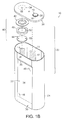
- FIG. 5A is a side view of the cell casing of the prismatic battery shown in FIG. 1A .
- FIG. 5B is a section view of the cell casing of FIG. 5A taken along line BB.
- FIG. 5C is a section view of another embodiment of a prismatic battery of the invention.
- FIG. 6A is a section view of the wall of the cell of the prismatic battery shown in FIG. 1A casing in a non-flexed position.
- FIG. 6B is a section view of the wall of the cell casing of FIG. 6A in a flexed position.
- FIG. 6C is a section view of the wall of the cell casing of FIG. 6A in a further flexed position.
- FIG. 7 is a section view of the wall of the cell casing of another embodiment of the invention in a non-flexed position.
- FIG. 8A is a view of the first conductive plate of the battery of the invention.
- FIG. 8B is a top view of the first conductive plate of the battery of the invention.
- FIG. 8C is a section view of the first conductive plate of FIG. 8B along line AA.
- terminals of the batteries of the invention mean the parts or surfaces of the batteries to which external electric circuits are connected.
- the batteries of the invention typically include a first terminal in electrical communication with a first electrode, and a second terminal in electrical communication with a second electrode.
- the first and second electrodes are contained within the cell casing of a battery of the invention, for example, in a “jelly roll” form.
- the first terminal can be either a positive terminal in electrical communication with a positive electrode of the battery, or a negative terminal in electrical communication with a negative electrode of the battery, and vice versa for the second terminal.
- the first terminal is a negative terminal in electrical communication with a negative electrode of the battery
- the second terminal is a positive terminal in electrical communication with a positive electrode of the battery.
- the phrase “electrically connected” or “in electrical communication” means certain parts are in communication with each other by flow of electrons through conductors, as opposed to electrochemical communication which involves flow of ions, such as Li + , through electrolytes.
- FIG. 1A shows an exploded view of battery 10 of one embodiment of the invention, in perspective.
- Battery 10 includes first electrode 12 and second electrode 14 .
- First electrode 12 is electrically connected to feed-through device 16 , which includes first component 18 , which is proximal to first electrode 12 , and second component 20 , which is distal to first electrode 12 .
- the electrodes 12 , 14 are placed inside battery can 22 that includes cell casing 24 and lid 26 , i.e., internal space 28 defined by cell casing 24 and lid 26 .
- Cell casing 24 and lid 26 of battery 10 are in electrical communication with each other.
- feed-through includes any material or device that connects electrode 12 of battery 10 , within internal space 28 defined by cell casing 24 and lid 26 , with a component of the battery external to that defined internal space.
- feed-through device 16 extends through a pass-through hole defined by lid 26 .
- Feed-through device 16 also can pass through lid 26 without deformation, such as bending, twisting and/or folding, and can increase cell capacity.
- One benefit of using such a feed-through device includes a potential increase (e.g., 5-15%) in cell capacity due to increased volume utilization, as compared to that of a conventional lithium battery in which current-carrying tabs are folded or bent into a cell casing and are welded with internal electrodes.
- Any other suitable means known in the art can be used in the invention to connect electrode 12 with a component of the battery external to battery can 22 , e.g., a terminal of the battery.
- Cell casing 24 and lid 26 can be made of any suitable conductive material which is essentially stable electrically and chemically at a given voltage of batteries, such as the lithium-ion batteries of the invention.
- suitable materials of cell casing 24 include aluminum, nickel, copper, steel, nickel-plated iron, stainless steel and combinations thereof.
- cell casing 24 is of or includes, aluminum.
- cell casing 24 is formed of anodized aluminum.
- the aluminum of cell casing 24 can be anodized before, during or after shaping an aluminum blank to form cell casing 24 .
- Cell casing 24 can be labeled by any suitable method known in the art, such as is described in U.S. Pat. No.
- a label can be formed on cell casing 24 by use of laser technology, as is known in the art.
- lid 26 is made of the same material as cell casing 24 .
- both cell casing 24 and lid 26 are formed of, or include, aluminum.
- the aluminum of lid 26 can be anodized.
- Lid 26 can hermetically seal cell casing 24 by any suitable method known in the art.
- lid 26 and cell casing 24 are welded to each other.
- other forms of electrical connection of lid 26 to cell casing 24 known in the art, such as crimping, can be employed in the invention.
- Battery can 22 for example, lid 26 , is electrically insulated from feed-through device 16 , for example, by an insulating gasket (not shown).
- the insulating gasket is formed of a suitable insulating material, such as polypropylene, polyvinylfluoride (PVF), etc.
- Cell casing 24 includes major surface 30 , which is generally planar relative to the remaining side surfaces of the casing, the remaining side surfaces typically being contoured such that a cross section of the casing has an oblong shape.
- Cell casing 24 also includes substantially planar recessed portion 32 of major surface area 30 , and ridge section 36 on a side of recessed portion 32 .
- a remainder 38 of major surface 30 is defined as the area of major surface 30 excluding recessed portion 32 and ridge portions 36 .
- FIG. 1B shows another embodiment of the invention, wherein there is only one ridge portion 36 .
- cell casing 24 is a 183665 prismatic cell casing constructed, at least in part, of aluminum.
- the wall of cell casing 24 is about 0.9 mm thick and width defined by planes at opposing major surfaces of about 18.20 mm.
- recessed portion 32 has a length of about 37 mm and a width of about 37 mm.
- the surface area of recessed portion 32 is in a range of between about 1200 mm 2 and about 1400 mm 2 .
- the surface area of the recessed portion is a range of between about 1248 mm 2 and about 1352 mm 2 .
- recessed portion 32 At zero gauge pressure, the maximum depth of recessed portion 32 from remainder 38 of major surface 30 is about 0.4 mm. Generally, recessed portion 32 typically will occupy between about 78% and about 85% of generally planar major surface area 30 . In another embodiment, recessed portion will occupy between about 75% and about 80% of generally planar surface area 30 . In the embodiment of the invention shown in FIG. 2B , ridge sections 36 border at least part of recessed portion 32 on one or two sides of recessed portion 32 .
- FIGS. 2A and 2B show top and side views, respectively, of the embodiment of cell casing 24 shown in FIG. 1A .
- recessed portion 32 has a length of about 37 mm and a width w of about 37 mm.
- FIG. 2C shows a cross-sectional view of cell casing 24 that shows the contours of one embodiment of the recessed portion 32 when the interior 28 of cell casing 24 is at about zero kilograms per square centimeter (kg/cm 2 ).
- gauge pressure refers to the difference between the absolute pressure in the battery casing interior and atmospheric pressure.
- FIG. 2D is a detail of FIG. 2C showing ridge section 36 of recessed portion 32 .
- Recessed portion 32 can be formed by any suitable technique known in the art, such as rolling, stamping, etc.
- recessed portion 32 is formed by use of an arbor 33 and punch 35 , shown in FIGS. 3A and 3B , respectively.
- Arbor 33 includes recess 37 .
- arbor 33 is inserted within the cell casing from an open end of the cell casing so that end 33 a of arbor 33 proximates closed end 33 b of cell casing 24 , shown in FIGS. 2B and 2C .
- Punch 35 shown in FIG. 3B , is then pressed into recess 37 at an end of recess 37 most proximate to the open end 33 c of cell casing 24 , thereby forming recessed portion 32 of cell casing 24 .
- Punch 35 shown in FIG.
- cell casing 24 is then removed from cell casing 24 and cell casing 24 can be removed from arbor 33 .
- recessed portion 32 will be substantially planar and merge into remainder 38 at one end of recessed portion 32 , thereby effectively resulting in cell casing 24 substantially as shown in FIG. 2 .
- the shape of cell casing 24 is formed by use of arbor 33 and punch 35 because recess 37 does not match punch 35 , in that recess 37 is open on one side to allow cell casing 24 to be removed from arbor 33 . In other words, there is effectively no ridge along one side of recessed portion 32 .
- FIGS. 4A-4C are schematic cross-sectional representations of major surface area 30 .
- FIG. 4A shows the major surface area in a non-flexed position, which typifies the shape of the casing when the battery is not being charged, or has an internal gauge pressure when a battery employing the casing is not being charged.
- the gauge pressure of a battery of the invention when not being charged is less than about 5 kg/cm 2 .
- plane 31 a defined by the boundary 72 between ridge section portion 36 and remainder 38 of major surface 30 is substantially aligned with the surface of remainder 38 of major surface 30 . This substantial alignment generally defines the original position of the plane at a time prior to undergoing an increase in gauge pressure, which is represented by plane 31 a.
- the gauge pressure can rise. As shown in FIG. 4B , when the gauge pressure of a battery of the invention increases, the increase in gauge pressure causes the plane defined by the boundary 72 between ridge portion 36 and remainder 38 of major surface 30 to move away from the original position.
- movement of the plane is a consequence of cooperation between recessed portion 32 and remainder 38 through ridge portion 36 .
- flexing of recessed portion 32 forces ridge sections 36 , and consequently its boundary 72 with remainder 38 , outwardly, thereby moving the plane to a second position.
- Plane 31 b represents the plane in the second position.
- recessed portion 32 flexes during recharging to a point beyond plane 31 a , but still within plane 31 b.
- At least a portion of recessed portion 32 flexes under an increase of gauge pressure to a point beyond a position of plane 31 a prior to the increase of gauge pressure, wherein boundary 74 between ridge portion 36 and recessed portion 32 remains recessed relative to plane 31 b defined by boundary 72 between ridge portions 36 and the remainder of major plane 38 up to a gauge pressure of at least 2 kg/cm 2 .
- At least a portion of recessed portion 72 flexes under the increase of pressure to a point beyond a position of plane 31 b during the increase of gauge pressure, and wherein boundary 74 between the ridge portion 36 and the recessed portion 32 remains recessed relative to plane 31 b defined by boundary 72 between ridge portions 36 and the remainder of major plane 38 up to a gauge pressure of at least 4 kg/cm 2 .
- recessed portion 32 flexes during recharging to a point beyond plane 31 b.
- a boundary between the ridge portion and the recessed portion remains recessed relative to the plane defined by the boundary between the ridge portions and the remainder of the major plane up to a gauge pressure of at least 4 kg/cm 2 .
- at least a portion of the recessed portion flexes under the increase of gauge pressure to a point beyond a position of the plane prior to the increase of pressure, wherein a boundary between the ridge portion and the recessed portion remains recessed relative to the plane defined by the boundary between the ridge portions and remainder of the major plane up to a gauge pressure of at least 2 kg/cm 2 .
- FIGS. 5A-5B and 6 A- 6 C ridge portions 36 oppose each other across recessed portion 32 , in contrast to the embodiment shown in FIGS. 2B , 2 C, and 4 A- 4 C.
- FIG. 5C shows another embodiment of the invention, wherein a plurality of ridge portion 36 are all essentially parallel to each other.
- the height of each ridge portion 36 is, independently, in a range of between about 0.2 mm and about 1.0 mm. In one embodiment the height of each ridge is about 0.4 mm.
- ridge portions 36 of generally planar major surface 30 has an arc shape, defined, for example, by the radius of a circle.
- the radius of the circle typically is in a range of between about 0.2 and 1.0 mm. In one embodiment, the radius of the circle is about 0.4 mm.
- the boundary 74 between ridge portion 36 and recessed portion 32 is defined at the point of tangency of recessed portion 74 from the arc.
- the boundary 74 between ridge portion 36 and recessed portion 32 remains recessed relative to the plane defined by the boundary 72 between ridge portions 36 and remainder 38 up to a gauge pressure of at least 40 kg/cm 2 .
- recessed portion 32 preferably returns to essentially its original position after recharging is complete.
- the position of the plane prior to an increase in gauge pressure i.e., plane 31 a , is substantially the same as the position of the plane upon return of the gauge pressure from an increased level.
- the width W of cell casing 24 which includes two recessed portions, one on each opposing side, as shown in FIG. 2A , extends from about 18.02 mm to no more than about 19.5 mm under a gauge pressure of about 12 kg/cm 2 .
- cell casing 24 is of anodized aluminum having a width W prior to flexing of about 18.02 mm, and a width W after pressurizing to about 11.14 kg/cm 2 of between about 18.4 mm and about 19.0 mm, whereas the same cell casing 24 of aluminum, without anodization, will expand in width W from 18.02 mm to a width W of between about 20.18 mm to about 20.40 mm.
- At least one of cell casing 24 and lid 26 of battery can 22 are in electrical communication with second electrode 14 of battery 10 through CID 40 .
- Battery can 22 i.e., cell casing 24 and lid 26 , is electrically insulated from a first terminal of battery 10 , and at least a portion of battery can 22 is at least a component of a second terminal of battery 10 , or is electrically connected to the second terminal.
- at least a portion of lid 26 or the bottom of cell casing 24 serves as a second terminal of battery 10
- feed-through device 16 includes top conductive layer 26 , which can serve as a first terminal of battery 10 in electrical communication with first electrode 12 .
- First component 18 , second component 20 and top conductive layer 26 each and independently can be made of any suitable conductive material known in the art, for example, nickel.
- Battery 10 of the invention includes CID 40 . Although one CID 40 is employed in battery 10 , more than one CID 40 can be employed in the invention.
- CID 40 includes first conductive plate 42 and second conductive plate 44 in electrical communication with each other (e.g., by welding, crimping, riveting, etc.). Second conductive plate 44 is in electrical communication with second electrode 14 , and first conductive plate 42 is in electrical contact with battery can 22 , for example, lid 26 .
- the first conductive plate includes a frustum having an essentially planar cap.
- first conductive plate 42 includes frustum 60 that includes first end 62 and second end 64 .
- First end 62 has a broader diameter (indicated with reference character “j” in FIG. 4C ) than the diameter of second end 64 (indicated with reference character “k” in FIG. 4C ).
- First conductive plate 42 also includes base 68 extending radially from a perimeter of first end 62 of frustum 60 .
- Essentially planar cap 70 seals second end 64 of frustum 60 .
- frustum means the basal wall part (excluding the bottom and top ends) of a solid right circular cone (i.e., solid generated by rotating a right triangle about one of its legs) by cutting off the top intersected between two parallel planes.
- second conductive plate 44 separates from (e.g., deforms away or is detached from) first conductive plate 42 when gauge pressure inside the battery is greater than a predetermined value, for example, between about 4 kg/cm 2 and about 15 kg/cm 2 , or between about 5 kg/cm 2 and about 10 kg/cm 2 , whereby a current flow between second electrode 14 and battery can 22 , at least a portion of which is at least a component of a second terminal, or is electrically connected to the second terminal, is interrupted.
- a predetermined value for example, between about 4 kg/cm 2 and about 15 kg/cm 2 , or between about 5 kg/cm 2 and about 10 kg/cm 2 , whereby a current flow between second electrode 14 and battery can 22 , at least a portion of which is at least a component of a second terminal, or is electrically connected to the second terminal, is interrupted.
- vent scores 46 e.g., at cell wall or the bottom part of cell casing 24 , or second conductive plate 44 , which will be discussed later in detail, when the internal pressure kept increasing and reaches a predetermined value for activation of vent scores 46 .
- the predetermined gauge pressure value for activation of vent scores 46 is higher than that for activation of CID 40 , for example, between about 5 kg/cm 2 and about 10 kg/cm 2 .
- This feature helps prevent premature gas leakage, which can damage neighboring batteries (or cells) which are operating normally. So, when one of a plurality of cells in the battery packs of the invention is damaged, the other healthy cells are not damaged.
- gauge pressure values or sub-ranges suitable for the activation of CID 40 and those for activation of venting means 58 are selected from among the predetermined gauge pressure ranges such that there is no overlap between the selected pressure values or sub-ranges.
- the values or ranges of gauge pressure for the activation of CID 40 and those for the activation of venting means 58 differ by at least about 2 kg/cm 2 pressure difference, more preferably by at least about 4 kg/cm 2 , even more preferably by at least about 6 kg/cm 2 , such as by about 7 kg/cm 2 .
- CID 40 further includes insulator 48 (e.g., insulating layer or insulating gasket) between a portion of first conductive plate 42 and second conductive plate 44 .
- CID 40 is in electrical communication with cell casing 24 of the battery.
- the second conductive plate 44 separates from (e.g., deforms away or is detached from) the first conductive plate when pressure inside the battery is greater than a predetermined value, for example, an internal gauge pressure in a range of between about 5 kg/cm 2 and about 10 kg/cm 2 , whereby a current flow between the second electrode and the second terminal is interrupted.
- At least one of first conductive plate 42 and insulator 48 of CID 40 includes at least one hole (e.g., holes 50 or 52 in FIG. 1 ) through which gas within battery 10 is in fluid communication with second conductive plate 44 .
- CID 40 further includes end plate 54 disposed over first conductive plate 42 , and defining at least one hole 56 through which first conductive plate 42 is in fluid communication with the atmosphere outside the battery.
- end plate 54 is a part of battery can 22 , as shown in FIG. 1 where end plate 54 is a part of lid 26 of battery can 22 .
- end plate 54 is at battery can 22 of battery 10 , for example, over, under or at lid 26 of battery can 22 , and in electrical communication with battery can 22 .
- CID 40 in the invention is placed within battery can 22 , or alternatively, a portion of CID 40 is within battery can 22 and another portion of CID 40 is at or above battery can 22 .
- CID 40 can be electrically connected to lid 24 by any suitable means, such as welding, crimping, etc.
- at least one component of CID 40 , first and second conductive plates, 42 , 44 , insulator 48 and end plate 54 are positioned within battery can 22 .
- At least one component of CID 40 e.g., first and second conductive plates, 42 , 44 , insulator 48 , and end plate 54 , is seated within a recess at battery can 22 , e.g., lid 24 .
- at least one of first and second conductive plates, 42 , 44 , and end plate 54 is a component of battery can 22 , e.g., lid 24 , or side or bottom of cell casing 22 .
- at least one of first and second conductive plates, 42 , 44 , and end plate 54 is a portion of battery can 22 , e.g., lid 24 , or side or bottom of cell casing 24 .
- first and second conductive plates, 42 , 44 , and end plate 54 is coined or stamped at lid 26 , or the side or the bottom of cell casing 24 , preferably at lid 54 .
- end plate 54 is a part of lid 24 (e.g., coined or stamped), and first and second conductive plates, 42 , 44 , are placed within cell casing 24 , as shown in FIG. 1 .
- First conductive plate 42 and second conductive plate 44 can be made of any suitable conductive material known in the art for a battery. Examples of suitable materials include aluminum, nickel and copper, preferably aluminum.
- battery can 22 e.g., cell casing 24 and lid 26
- first conductive plate 42 and second conductive plate 44 are made of substantially the same metals.
- substantially same metals means metals that have substantially the same chemical and electrochemical stability at a given voltage, e.g., the operation voltage of a battery.
- battery can 22 , first conductive plate 42 and second conductive plate 44 are made of the same metal, such as aluminum, wherein battery can 22 , first conductive plate 42 and second conductive plate 44 are all in electrical communication with the second terminal, and were the second terminal is in electrical communication with second electrode 14 , and wherein the second electrode is a cathode.
- Cell casing 24 (e.g., the cell wall or the bottom part) includes at least one venting means 58 as a means for venting internal space 28 when necessary, such as when gauge pressure within lithium ion battery 10 is greater than a value of between about 10 kg/cm 2 and about 20 kg/cm 2 .
- second conductive plate 44 includes at least one venting means, such as vent scores 46 , although it is to be understood that any suitable type of venting means can be employed as long as the means provide hermetic sealing in normal battery operation conditions.
- the term “score” means partial incision of section(s) of a cell casing, such as cell casing 24 , that is designed to allow the cell pressure and any internal cell components to be released at a defined internal gauge pressure, (e.g., between about 10 and about 20 kg/cm 2 ).
- the vent score is directionally positioned away from a user/or neighboring cells.
- more than one vent score can be employed.
- pattern vent scores can be employed.
- the vent score can be parallel, perpendicular, diagonal to a major stretching (or drawing) direction of the cell casing material during creation of the shape of cell casing 24 . Consideration is also given to vent score properties, such as depth, shape and length (size).
- the batteries of the invention can further include a positive thermal coefficient layer (PTC) in electrical communication with either the first terminal or the second terminal, preferably in electrical communication with the first terminal.
- PTC positive thermal coefficient layer
- Suitable PTC materials are those known in the art. Generally, suitable PTC materials are those that, when exposed to an electrical current in excess of a design threshold, its electrical conductivity decreases with increasing temperature by several orders of magnitude (e.g., 10 4 to 10 6 or more). Once the electrical current is reduced below a suitable threshold, in general, the PTC material substantially returns to the initial electrical resistivity.
- the PTC material includes small quantities of semiconductor material in a polycrystalline ceramic, or a slice of plastic or polymer with carbon grains embedded in it.
- the semiconductor material or the plastic or polymer with embedded carbon grains forms a barrier to the flow of electricity and causes electrical resistance to increase precipitously.
- the temperature at which electrical resistivity precipitously increases can be varied by adjusting the composition of the PTC material, as is known in the art.
- An “operating temperature” of the PTC material is a temperature at which the PTC exhibits an electrical resistivity about half way between its highest and lowest electrical resistance.
- the operating temperature of the FTC layer employed in the invention is between about 70° Celsius and about 150° Celsius.
- Examples of specific PTC materials include polycrystalline ceramics containing small quantities of barium titanate (BaTiO 3 ), and polyolefins including carbon grains embedded therein.
- Examples of commercially available PTC laminates that include a PTC layer sandwiched between two conducting metal layers include LIP and LR4 series manufactured by Raychem Co. Generally, the PTC layer has a thickness in a range of about 50 ⁇ m and about 300 ⁇ m.
- the PTC layer includes electrically conductive surface, the total area of which is at least about 25% or at least about 50% (e.g., about 48% or about 56%) of the total surface area of lid 26 or the bottom of battery 10 .
- the total surface area of the electrically conductive surface of the PTC layer can be at least about 56% of the total surface area of lid 26 or the bottom of battery 10 .
- Up to 100% of the total surface area of lid 26 of battery 10 can occupied by the electrically conductive surface of the PTC layer.
- the whole, or part, of the bottom of battery 10 can be occupied by the electrically conductive surface of the PTC layer.
- the PTC layer can be positioned internally or externally to the cell can (e.g., lid 22 or the bottom part of cell casing 24 ), preferably externally to the cell can, for example, over lid 26 of the cell can.
- the PTC layer is between a first conductive layer and a second conductive layer and at least a portion of the second conductive layer is at least a component of the first terminal, or is electrically connected to the first terminal.
- the first conductive layer is connected to the feed-through device. Suitable examples of such a PTC layer sandwiched between the first and second conductive layers are described in U.S. patent application Ser. No. 11/474,081, filed on Jun. 23, 2006, the entire teachings of which are incorporated herein by reference.
- the cells or batteries of the invention are prismatic, as shown in FIG. 1 (stacked or wound, e.g., 183665 or 103450 configuration).
- the cells or batteries of the invention are of a prismatic shape that is oblong.
- the present invention can use all types of prismatic cell casings, an oblong cell casing is preferred partly due to the two features described below.
- an oblong shape such as the 183665 form factor
- the available internal volume of an oblong shape is larger than the volume of two 18650 cells, when comparing stacks of the same external volume.
- the oblong cell When assembled into a battery pack, the oblong cell fully utilizes more of the space that is occupied by the battery pack.
- This enables novel design changes to the internal cell components that can increase key performance features without sacrificing cell capacity relative to that found in the industry today.
- Due to the larger available volume one can elect to use thinner electrodes, which have relatively higher cycle life and a higher rate capability.
- an oblong can has larger flexibility. For instance, an oblong shape can flex more at the waist point compared to a cylindrically shaped can, which allows less flexibility as stack pressure is increasing upon charging. The increased flexibility decreases mechanical fatigue on the electrodes, which, in turn, causes higher cycle life. Also, clogging of pores of a separator in batteries can be improved by the relatively lower stack pressure.
- the oblong shape provides a snug fit to the jelly roll, which minimizes the amount of electrolyte necessary for the battery.
- the relatively lower amount of electrolyte results in less available reactive material during a misuse scenario and hence higher safety.
- cost is lower due to a lower amount of electrolyte.
- a prismatic can with a stacked electrode structure, whose cross-section is in a rectangular shape full volume utilization is possible without unnecessary electrolyte, but this type of can design is more difficult and hence more costly from a manufacturing point-of-view.
- At least one cell has a prismatic shaped cell casing, and more preferably, an oblong shaped cell casing, as shown in FIG. 1 . More preferably, at least one cell has an 183665 configuration.
- the capacity of the cells in the battery pack is typically equal to or greater than about 3.0 Ah, more preferably equal to or greater than about 4.0 Ah.
- the internal impedance of the cells is preferably less than about 50 milliohms, and more preferably less than 30 milliohms.
- the lithium-ion batteries and battery packs of the invention can be used for portable power devices, such as portable computers, power tools, toys, portable phones, camcorders, PDAs and the like.
- portable electronic devices such as portable computers, power tools, toys, portable phones, camcorders, PDAs and the like.
- their charges are, in general, designed for a 4.20 V charging voltage.
- the lithium-ion batteries and battery packs of the invention are particularly useful for these portable electronic devices.
- the present invention also includes methods of producing a battery, such as a lithium-ion battery, as described above.
- the methods include forming a cell casing as described above, and disposing a first electrode and a second electrode within the cell casing.
- a current interrupt device, as described above e.g., current interrupt device 28 , is formed and electrically connected with the cell casing.
- Positive and negative electrodes and electrolytes for the lithium-ion batteries of the invention can be formed by suitable methods known in the art.
- suitable negative-active materials for the negative electrodes include any material allowing lithium to be doped or undoped in or from the material.
- suitable negative-active materials include carbonaceous materials, for example, non-graphitic carbon, artificial carbon, artificial graphite, natural graphite, pyrolytic carbons, cokes such as pitch coke, needle coke, petroleum coke, graphite, vitreous carbons, or a heat-treated organic polymer compounds obtained by carbonizing phenol resins, furan resins, or similar, carbon fibers, and activated carbon.
- metallic lithium, lithium alloys, and an alloy or compound thereof are usable as the negative active materials.
- the metal element or semiconductor element allowed to form an alloy or compound with lithium may be a group IV metal element or semiconductor element, such as but not limited to, silicon or tin.
- amorphous tin that is doped with a transition metal such as cobalt or iron/nickel, is a metal that is suitable as an anode material in these types of batteries.
- Oxides allowing lithium to be doped or undoped in or out from the oxide at a relatively basic potential, such as iron oxide, ruthenium oxide, molybdenum oxide, tungsten oxide, titanium oxide, and tin oxide, and nitrides, similarly, are usable as the negative-active materials.
- Suitable positive-active materials for the positive electrodes include any material known in the art, for example, lithium nickelate (e.g., Li 1+x NiM′O 2 ), lithium cobaltate (e.g., Li 1+x CoO 2 ), olivine-type compounds (e.g., Li 1+x FePO 4 ), manganate spinel (e.g., Li 1+x9 Mn 2 ⁇ y9 O 4 (x9 and y9 are each independently equal to or greater than zero and equal to or less than 0.3) or Li 1+x1 (Mn 1 ⁇ y1 A′ y2 ) 2 ⁇ x2 O z1 ) (x1 and x2 are each independently equal to or greater than 0.01 and equal to or less than 0.3; y1 and y2 are each independently equal to or greater than 0.0 and equal to or less than 0.3; z1 is equal to or greater than 3.9 and equal to or less than 4.1), and mixtures thereof.
- lithium nickelate e.g., Li 1+x Ni
- the positive-active materials for the positive electrodes of the invention include a lithium cobaltate, such as Li (1+x8) CoO z8 . More specifically, a mixture of about 60-90 wt % (e.g. about 80 wt %) of a lithium cobaltate, such as Li (1+x8) CoO z8 , and about 40-10 wt % (e.g., about 20 wt %) of a manganate spinel (e.g., having about 100-115 mAh/g), such as Li (1+x1) Mn 2 O z1 , preferably Li (1+x1) Mn 2 O 4 , is employed for the invention.
- a lithium cobaltate such as Li (1+x8) CoO z8
- the value x1 is equal to or greater than zero and equal to or less than 0.3 (e.g., 0.05 ⁇ x1 ⁇ 0.15).
- the value z1 is equal to or greater than 3.9 and equal to or greater than 4.2.
- the value x8 is equal to or greater than zero and equal to or less than 0.2.
- the value z8 is equal to or greater than 1.9 and equal to or greater than 2.1.
- the positive-active materials for the invention include a mixture that includes a lithium cobaltate, such as Li (1+x8) CoO z8 , and a manganate spinel represented by an empirical formula of Li (1+x1) (Mn 1 ⁇ y1 A′ y2 ) 2 ⁇ x2 O z1 .
- the values x1 and x2 are each independently equal to or greater than 0.01 and equal to or less than 0.3.
- the values y1 and y2 are each independently equal to or greater than 0.0 and equal to or less than 0.3.
- the value z1 is equal to or greater than 3.9 and equal to or less than 4.2.
- A′ is at least one member of the group consisting of magnesium, aluminum, cobalt, nickel and chromium. More specifically, the lithium cobaltate and the manganate spinel are in a weight ratio of lithium cobaltate:manganate spinel between about 0.95:0.05 and about 0.9:0.1 to about 0.6:0.4.
- the positive-active materials for the invention include a mixture that includes 100% of a lithium cobaltate, such as Li (1+x8) CoO z8 .
- the positive-active materials for the invention include at least one lithium oxide selected from the group consisting of: a) a lithium cobaltate; b) a lithium nickelate; c) a manganate spinel represented by an empirical formula of Li (1+x1) (Mn 1 ⁇ y1 A′ y2 ) 2 ⁇ x2 O z1 ; d) a manganate spinel represented by an empirical formula of Li (1+x1) Mn 2 O z1 or Li 1+x9 Mn 2 ⁇ y9 O 4 ; and e) an olivine compound represented by an empirical formula of Li (1+x10) A′′ x10 MPO 4 .
- the values of x1, z1, x9 and y9 are as described above.
- the value, x2 is equal to or greater than 0.01 and equal to or less than 0.3.
- the values of y1 and y2 are each independently equal to or greater than 0.0 and equal to or less than 0.3.
- A′ is at least one member of the group consisting of magnesium, aluminum, cobalt, nickel and chromium.
- the value, x10 is equal to or greater than 0.05 and equal to or less than 0.2, or the value, x10, is equal to or greater than 0.0 and equal to or less than 0.1.
- M is at least one member of the group consisting of iron, manganese, cobalt and magnesium.
- A′′ is at least one member of the group consisting of sodium, magnesium, calcium, potassium, nickel and niobium.
- a lithium nickelate that can be used in the invention includes at least one modifier of either the Li atom or Ni atom, or both.
- a “modifier” means a substituent atom that occupies a site of the Li atom or Ni atom, or both, in a crystal structure of LiNiO 2 .
- the lithium nickelate includes only a modifier of, or substituent for, Li atoms (“Li modifier”).
- the lithium nickelate includes only a modifier of or substituent for, Ni atoms (“Ni modifier”).
- the lithium nickelate includes both the Li and Ni modifiers. Examples of Li modifiers include barium (Ba), magnesium (Mg), calcium (Ca) and strontium (Sr).
- Ni modifiers include those modifiers for Li and, in addition, aluminum (Al), manganese (Mn) and boron (B).
- Other examples of Ni modifiers include cobalt (Co) and titanium (Ti).
- the lithium nickelate is coated with LiCoO 2 .
- the coating can be, for example, a gradient coating or a spot-wise coating.
- Li x3 Ni 1 ⁇ z3 M′ z3 O 2 where 0.05 ⁇ x3 ⁇ 1.2 and 0 ⁇ z3 ⁇ 0.5
- M′ is one or more elements selected from a group consisting of Co, Mn, Al, B, Ti, Mg, Ca and Sr.
- M′ is one or more elements selected from a group consisting of Mn, Al, B, Ti, Mg, Ca and Sr.
- Li x4 A* x5 Ni (1 ⁇ y4 ⁇ z4) Co y4 Q z4 O a x4 is equal to or greater than about 0.1 and equal to or less than about 1.3; x5 is equal to or greater than 0.0 and equal to or less than about 0.2; y4 is equal to or greater than 0.0 and equal to or less than about 0.2; z4 is equal to or greater than 0.0 and equal to or less than about 0.2; a is greater than about 1.5 and less than about 2.1; A* is at least one member of the group consisting of barium (Ba), magnesium (Mg) and calcium (Ca); and Q is at least one member of the group consisting of aluminum (Al), manganese (Mn) and boron (B), Preferably, y4 is greater than zero.
- x5 is equal to zero, and z4 is greater than 0.0 and equal to or less than about 0.2. In another embodiment, z4 is equal to zero, and x5 is greater than 0.0 and equal to or less than about 0.2. In yet another embodiment, x5 and z4 are each independently greater than 0.0 and equal to or less than about 0.2. In yet another embodiment, x5, y4 and z4 are each independently greater than 0.0 and equal to or less than about 0.2.
- Various examples of lithium nickelates where x5, y4 and z4 are each independently greater than 0.0 and equal to or less than about 0.2 can be found in U.S. Pat. Nos. 6,855,461 and 6,921,609 (the entire teachings of which are incorporated herein by reference).
- a specific example of the lithium nickelate is LiNi 0.8 Co 0.15 Al 0.05 O 2 .
- a preferred specific example is LiCoO 2 -coated LiNi 0.8 Co 0.15 Al 0.05 O 2 .
- LiCoO 2 doe not fully coat the nickelate core particle.
- the composition of LiNi 0.8 Co 0.15 Al 0.05 O 2 coated with LiCoO 2 can naturally deviate slightly in composition from the 0.8:0.15:0.05 weight ratio between Ni:Co:Al. The deviation can range about 10-15% for the Ni, 5-10% for Co and 2-4% for Al.
- Another specific example of the lithium nickelate is Li 0.97 Mg 0.03 Ni 0.9 Co 0.1 O 2 .
- a preferred specific example is LiCoO 2 -coated Li 0.97 Mg 0.03 Ni 0.9 Co 0.1 O 2 .
- the composition of Li 0.97 Mg 0.03 Ni 0.9 Co 0.1 O 2 coated with LiCoO 2 can deviate slightly in composition from the 0.03:0.9:0.1 weight ratio between Mg:Ni:Co. The deviation can range about 2-4% for Mg, 10-15% for Ni and 5-10% for Co.
- Another preferred nickelate that can be used in the present invention is Li(Ni 1/3 Co 1/3 Mn 1/3 )O 2 , also called “333-type nickelate.” This 333-type nickelate optionally can be coated with LiCoO 2 , as described above.
- lithium cobaltates that can be used in the invention include Li 1+x8 CoO 2 that is modified by at least one of Li or Co atoms.
- Li modifiers are as described above for Li of lithium nickelates.
- Co modifiers include the modifiers for Li and aluminum (Al), manganese (Mn) and boron (B).
- Ni nickel
- Ti titanium
- lithium cobaltates represented by an empirical formula of Li x6 M′ y6 Co (1 ⁇ z6) M′′ z6 O 2 , where x6 is greater than 0.05 and less than 1.2; y6 is greater than 0 and less than 0.1, z6 is equal to or greater than 0 and less than 0.5; M′ is at least one member of magnesium (Mg) and sodium (Na) and M′′ is at least one member of the group consisting of manganese (Mn), aluminum (Al), boron (B), titanium (Ti), magnesium (Mg), calcium (Ca) and strontium (Sr), can be used in the invention.
- Mn manganese
- Al aluminum
- B boron
- Ti titanium
- Mg magnesium
- Ca calcium
- lithium cobaltate that can be used in the invention is unmodified Li 1+x8 CoO 2 , such as LiCoO 2 .
- the lithium cobaltate e.g., LiCoO 2
- the lithium cobaltate doped with Mg and/or coated with a refractive oxide or phosphate, such as ZrO 2 or Al(PO 4 ).
- lithium oxide compounds employed have a spherical-like morphology, since it is believed that this improves packing and other production-related characteristics.
- a crystal structure of each of the lithium cobaltate and lithium nickelate is independently a R-3m type space group (rhombohedral, including distorted rhombohedral).
- a crystal structure of the lithium nickelate can be in a monoclinic space group (e.g., P2/m or C2/m).
- olivine compounds that are suitable for use in the invention are generally represented by a general formula Li 1-x2 A′′ x2 MPO 4 , where x2 is equal to or greater than 0.05, or x2 is equal to or greater than 0.0 and equal to or greater than 0.1; M is one or more elements selected from a group consisting of Fe, Mn, Co, or Mg; and A′′ is selected from a group consisting of Na, Mg, Ca, K, Ni, Nb.
- M is Fe or Mn. More preferably, LiFePO 4 or LiMnPO 4 , or both are used in the invention.
- the olivine compounds are coated with a material having relatively high electrical conductivity, such as carbon.
- LiFePO 4 carbon-coated LiFePO 4 or carbon-coated.
- LiMnPO 4 is employed in the invention.
- olivine compounds where M is Fe or Mn can be found in U.S. Pat. No. 5,910,382 (the entire teachings of which are incorporated herein by reference).
- the olivine compounds typically have a small change in crystal structure upon charging/discharging, which generally makes the olivine compounds superior in terms of cycle characteristics. Also, safety is generally high, even when a battery is exposed to a high temperature environment.
- Another advantage of olivine compounds e.g., LiFePO 4 and LiMnPO 4 ) is their relatively low cost.
- Manganate spinel compounds have a manganese base, such as LiMn 2 O 4 . While the manganate spinel compounds typically have relatively low specific capacity (e.g., in a range of about 110 to 115 mAh/g), they have relatively high power delivery when formulated into electrodes and typically are safe in terms of chemical reactivity at higher temperatures. Another advantage of the manganate spinel compounds is their relatively low cost.
- A′ is one or more of Mg, Al, Co, Ni and Cr; x1 and x2 are each independently equal to or greater than 0.01 and equal to or less than 0.3; y1 and y2 are each independently equal to or greater than 0.0 and equal to or less than 0.3; z1 is equal to or greater than 3.9 and equal to or less than 4.1.
- A′ includes a M 3+ ion, such as Al 3+ , Co 3+ , Ni 3+ and Cr 3+ , more preferably Al 3+ .
- the manganate spinel compounds of Li (1+x1) (Mn 1 ⁇ y1 A′ y2 ) 2 ⁇ x2 O z1 can have enhanced cyclability and power compared to those of LiMn 2 O 4 .
- Another type of manganate spinel compounds that can be used in the invention is represented by an empirical formula of Li (1+x1) Mn 2 O z1 , where x1 and z1 are each independently the same as described above.
- the manganate spinel for the invention includes a compound represented by an empirical formula of Li 1+x9 Mn 2 ⁇ y9 O z9 where x9 and y9 are each independently equal to or greater than 0.0 and equal to or less than 0.3 (e.g., 0.05 ⁇ , x9, y9 ⁇ 0.15); and z9 is equal to or greater than 3.9 and equal to or less than 4.2.
- Specific examples of the manganate spinel that can be used in the invention include LiMn 1.9 Al 0.1 O 4 , Li 1+x1 , Mn 2 O 4 , Li 1+x7 Mn 2 ⁇ y7 O 4 , and their variations with Al and Mg modifiers.
- cathode materials described herein are characterized by empirical formulas that exist upon manufacture of lithium-ion batteries in which they are incorporated. It is understood that their specific compositions thereafter are subject to variation pursuant to their electrochemical reactions that occur during use (e.g., charging and discharging).
- non-aqueous electrolytes examples include a non-aqueous electrolytic solution prepared by dissolving an electrolyte salt in a non-aqueous solvent, a solid electrolyte (inorganic electrolyte or polymer electrolyte containing an electrolyte salt), and a solid or gel-like electrolyte prepared by mixing or dissolving an electrolyte in a polymer compound or the like.
- the non-aqueous electrolytic solution is typically prepared by dissolving a salt in an organic solvent.
- the organic solvent can include any suitable type that has been generally used for batteries of this type. Examples of such organic solvents include propylene carbonate (PC), ethylene carbonate (EC), diethyl carbonate (DEC), dimethyl carbonate (DMC), 1,2-dimethoxyethane, 1,2-diethoxyethane, ⁇ -butyrolactone, tetrahydrofuran, 2-methyl tetrahydrofuran, 1,3-dioxolane, 4-methyl-1,3-dioxolane, diethyl ether, sulfolane, methylsulfolane, acetonitrile, propionitrile, anisole, acetate, butyrate, propionate and the like. It is preferred to use cyclic carbonates such as propylene carbonate, or chain carbonates such as dimethyl carbonate and diethyl carbonate. These organic solvents can be used singly or
- Additives or stabilizers may also be present in the electrolyte, such as VC (vinyl carbonate), VEC (vinyl ethylene carbonate), EA (ethylene acetate), TPP (triphenylphosphate), phosphazenes, biphenyl (BP), cyclohexylbenzene (CHB), 2,2-diphenylpropane (DP), lithium bis(oxalato)borate (LiBoB), ethylene sulfate (ES) and propylene sulfate.
- VC vinyl carbonate
- VEC vinyl ethylene carbonate
- EA ethylene acetate
- TPP triphenylphosphate
- DP cyclohexylbenzene
- DP 2,2-diphenylpropane
- LiBoB lithium bis(oxalato)borate
- ES ethylene sulfate
- propylene sulfate propylene sulfate
- the solid electrolyte can include an inorganic electrolyte, a polymer electrolyte and the like insofar as the material has lithium-ion conductivity.
- the inorganic electrolyte can include, for example, lithium nitride, lithium iodide and the like.
- the polymer electrolyte is composed of an electrolyte salt and a polymer compound in which the electrolyte salt is dissolved.
- the polymer compounds used for the polymer electrolyte include ether-based polymers such as polyethylene oxide and cross-linked polyethylene oxide, polymethacrylate ester-based polymers, acrylate-based polymers and the like. These polymers may be used singly, or in the form of a mixture or a copolymer of two kinds or more.
- a matrix of the gel electrolyte may be any polymer insofar as the polymer is gelated by absorbing the above-described non-aqueous electrolytic solution.
- the polymers used for the gel electrolyte include fluorocarbon polymers such as polyvinylidene fluoride (PVDF), polyvinylidene-co-hexafluoropropylene (PVDF-HFP) and the like.
- Examples of the polymers used for the gel electrolyte also include polyacrylonitrile and a copolymer of polyacrylonitrile.
- Examples of monomers (vinyl based monomers) used for copolymerization include vinyl acetate, methyl methacrylate, butyl methacylate, methyl acrylate, butyl acrylate, itaconic acid, hydrogenated methyl acrylate, hydrogenated ethyl acrylate, acrylamide, vinyl chloride, vinylidene fluoride, and vinylidene chloride.
- polymers used for the gel electrolyte further include acrylonitrile-butadiene copolymer rubber, acrylonitrile-butadiene-styrene copolymer resin, acrylonitrile-chlorinated polyethylene-propylenediene-styrene copolymer resin, acrylonitrile-vinyl chloride copolymer resin, acrylonitrile-methacylate resin, and acrylonitrile-acrylate copolymer resin.
- acrylonitrile-butadiene copolymer rubber acrylonitrile-butadiene-styrene copolymer resin
- acrylonitrile-chlorinated polyethylene-propylenediene-styrene copolymer resin acrylonitrile-vinyl chloride copolymer resin
- acrylonitrile-methacylate resin acrylonitrile-acrylate copolymer resin.
- polymers used for the gel electrolyte include ether based polymers such as polyethylene oxide, copolymer of polyethylene oxide, and cross-linked polyethylene oxide.
- monomers used for copolymerization include polypropylene oxide, methyl methacrylate, butyl methacylate, methyl acrylate, butyl acrylate.
- a fluorocarbon polymer is preferably used for the matrix of the gel electrolyte.
- the electrolyte salt used in the electrolyte may be any electrolyte salt suitable for batteries of this type.
- the electrolyte salts include LiClO 4 , LiAsF 6 , LiPF 6 , LiBF 4 , LiB(C 6 H 5 ) 4 , LiB(C 2 O 4 ) 2 , CH 3 SO 3 Li, CF 3 SO 3 Li, LiCl, LiBr and the like.
- a separator separates the positive electrode from the negative electrode of the batteries.
- the separator can include any film-like material having been generally used for forming separators of non-aqueous electrolyte secondary batteries of this type, for example, a microporous polymer film made from polypropylene, polyethylene, or a layered combination of the two.
- a microporous separator made of glass fiber or cellulose material can in certain cases also be used. Separator thickness is typically between 9 and 25 ⁇ m.
- a positive electrode can be produced by mixing the cathode powders at a specific ratio. 90 wt % of this blend is then mixed together with 5 wt % of acetylene black as a conductive agent, and 5 wt % of PVDF as a binder. The mix is dispersed in N-methyl-2-pyrrolidone (NMP) as a solvent, in order to prepare slurry. This slurry is then applied to both surfaces of an aluminum current collector foil, having a typical thickness of about 20 um, and dried at about 100-150° C. The dried electrode is then calendared by a roll press, to obtain a compressed positive electrode.
- NMP N-methyl-2-pyrrolidone
- a negative electrode can be prepared by mixing 93 Wt % of graphite as a negative active material, 3 wt % acetylene black, and 4 wt % of PVDF as a binder.
- the negative mix was also dispersed in N-methyl-2-pyrrolidone as a solvent, in order to prepare the slurry.
- the negative mix slurry was uniformly applied on both surfaces of a strip-like copper negative current collector foil, having a typical thickness of about 10 um.
- the dried electrode is then calendared by a roll press to obtain a dense negative electrode.
- the negative and positive electrodes and a separator formed of a polyethylene film with micro pores, of thickness 25 um, are generally laminated and spirally wound to produce a spiral type electrode element.
- one or more positive lead strips are attached to the positive current electrode, and then electrically connected to the positive terminal of the batteries of the invention.
- a negative lead made of, e.g., nickel metal, connects the negative electrode, and then attached to a feed-through device, such as feed-through device 16 .
- An electrolyte of for instance EC:DMC:DEC with 1M LiPF 6 is vacuum filled in the cell casing of a lithium-ion battery of the invention, where the cell casing has the spirally wound “jelly roll.”
Priority Applications (1)
| Application Number | Priority Date | Filing Date | Title |
|---|---|---|---|
| US12/814,821 US9252399B2 (en) | 2009-06-16 | 2010-06-14 | Prismatic storage battery or cell with flexible recessed portion |
Applications Claiming Priority (2)
| Application Number | Priority Date | Filing Date | Title |
|---|---|---|---|
| US18755209P | 2009-06-16 | 2009-06-16 | |
| US12/814,821 US9252399B2 (en) | 2009-06-16 | 2010-06-14 | Prismatic storage battery or cell with flexible recessed portion |
Publications (2)
| Publication Number | Publication Date |
|---|---|
| US20110033734A1 US20110033734A1 (en) | 2011-02-10 |
| US9252399B2 true US9252399B2 (en) | 2016-02-02 |
Family
ID=43356999
Family Applications (1)
| Application Number | Title | Priority Date | Filing Date |
|---|---|---|---|
| US12/814,821 Expired - Fee Related US9252399B2 (en) | 2009-06-16 | 2010-06-14 | Prismatic storage battery or cell with flexible recessed portion |
Country Status (5)
| Country | Link |
|---|---|
| US (1) | US9252399B2 (zh) |
| EP (1) | EP2443684A4 (zh) |
| CN (1) | CN102460770B (zh) |
| TW (1) | TWI509863B (zh) |
| WO (1) | WO2010147869A2 (zh) |
Cited By (2)
| Publication number | Priority date | Publication date | Assignee | Title |
|---|---|---|---|---|
| US10707531B1 (en) | 2016-09-27 | 2020-07-07 | New Dominion Enterprises Inc. | All-inorganic solvents for electrolytes |
| US10707526B2 (en) | 2015-03-27 | 2020-07-07 | New Dominion Enterprises Inc. | All-inorganic solvents for electrolytes |
Families Citing this family (7)
| Publication number | Priority date | Publication date | Assignee | Title |
|---|---|---|---|---|
| JP5712804B2 (ja) * | 2011-06-09 | 2015-05-07 | トヨタ自動車株式会社 | 密閉型電池及びその製造方法 |
| CN102427114A (zh) * | 2011-12-02 | 2012-04-25 | 苏州冠硕新能源有限公司 | 电池及其中的电池壳 |
| KR101422656B1 (ko) * | 2012-02-07 | 2014-07-23 | 주식회사 엘지화학 | 신규한 구조의 내장형 전지셀 |
| US9473020B2 (en) * | 2013-12-13 | 2016-10-18 | 2Nd Life Tech. Llc | Systems and methods for a battery life extender |
| DE102018211244A1 (de) * | 2018-07-07 | 2020-01-09 | Robert Bosch Gmbh | Batteriezelle |
| CN209045702U (zh) * | 2018-11-14 | 2019-06-28 | 东莞新能源科技有限公司 | 一种电芯以及封装装置 |
| KR20210069974A (ko) | 2019-12-04 | 2021-06-14 | 에스케이이노베이션 주식회사 | 셀케이스유닛 및 이를 포함하는 배터리 모듈 |
Citations (33)
| Publication number | Priority date | Publication date | Assignee | Title |
|---|---|---|---|---|
| US4567121A (en) | 1984-06-08 | 1986-01-28 | Venture Technology Limited | Insulating seal for electrochemical cells |
| US5744261A (en) | 1992-05-21 | 1998-04-28 | Wilson Greatbatch Ltd. | Insulating inclosure for lithium batteries |
| US5958088A (en) * | 1998-03-04 | 1999-09-28 | Duracell, Inc. | Prismatic cell construction |
| JP2000037821A (ja) | 1998-07-24 | 2000-02-08 | Dainippon Printing Co Ltd | 内装用化粧材 |
| US6232015B1 (en) * | 1998-03-30 | 2001-05-15 | Renata Ag | Prismatic storage battery or cell with rigid compressive container |
| JP2001155693A (ja) | 1999-11-25 | 2001-06-08 | Nec Mobile Energy Kk | 密閉型電池 |
| US6430517B1 (en) | 1999-10-05 | 2002-08-06 | Ericsson Inc. | Circuits, user terminals, and methods for determining information associated with pin limited devices using excitations of different frequencies |
| US6444350B1 (en) | 1999-03-12 | 2002-09-03 | Sanyo Electronic Co., Ltd. | Battery unit which can detect an abnormal temperature rise of at least one of a plurality of cells |
| JP2002359009A (ja) | 2001-05-31 | 2002-12-13 | Sanyo Electric Co Ltd | 充電器 |
| US20030001578A1 (en) | 2001-06-29 | 2003-01-02 | Lam Peter Ar-Fu | Hand mounted control apparatus |
| US20030063900A1 (en) | 2001-12-13 | 2003-04-03 | Carter Group, Inc. | Linear electric motor controller and system for providing linear speed control |
| US20030122527A1 (en) | 2001-12-27 | 2003-07-03 | Masaki Yugo | Power supply |
| JP2004179019A (ja) | 2002-11-28 | 2004-06-24 | Sony Corp | 非水電解質二次電池用電極及び非水電解質二次電池 |
| US20050077878A1 (en) | 2003-10-14 | 2005-04-14 | Dave Carrier | Protection methods, protection circuits and protective devices for secondary batteries, a power tool, charger and battery pack adapted to provide protection against fault conditions in the battery pack |
| US20050206347A1 (en) | 2004-03-18 | 2005-09-22 | Kazuhiro Seo | Power supply apparatus |
| CN1728436A (zh) | 2004-07-29 | 2006-02-01 | 三星Sdi株式会社 | 二次电池 |
| US20060028183A1 (en) | 2004-07-23 | 2006-02-09 | Ryosaku Izawa | Battery device of vehicle power supply |
| WO2006071972A2 (en) | 2004-12-28 | 2006-07-06 | Boston-Power, Inc. | Lithium-ion secondary battery |
| US20070018780A1 (en) | 2005-07-06 | 2007-01-25 | Kimihiko Furukawa | Car power source apparatus |
| US20070026315A1 (en) | 2004-12-28 | 2007-02-01 | Lampe-Onnerud Christina M | Lithium-ion secondary battery |
| US20070120537A1 (en) | 2005-11-30 | 2007-05-31 | Panasonic Ev Energy Co., Ltd. | Controller for rechargeable battery and temperature estimation method and deterioration determination method for rechargeable battery |
| US20080007211A1 (en) | 2006-06-30 | 2008-01-10 | David Poisner | Battery charger chute |
| US20080212643A1 (en) | 2007-03-02 | 2008-09-04 | Mcgahhey D David | Temperature monitoring device |
| JP2008295291A (ja) | 2007-04-27 | 2008-12-04 | Sanyo Electric Co Ltd | 電源装置及び電動車輌 |
| US20090011324A1 (en) | 2007-07-06 | 2009-01-08 | Thomas Heinrich | Rechargeable battery and battery pack |
| US20090029193A1 (en) * | 2007-06-22 | 2009-01-29 | Boston-Power, Inc. | CID retention device for Li-ion cell |
| US20090117451A1 (en) | 2007-11-01 | 2009-05-07 | Samsung Sdi Co., Ltd. | Cap assembly and secondary battery using the same |
| US20090167238A1 (en) | 2008-01-02 | 2009-07-02 | Cooper Technologies Company | Method and system for float charging a battery |
| US20090259420A1 (en) | 2008-04-11 | 2009-10-15 | Apple Inc. | Adaptive surface concentration battery charging |
| US20090315510A1 (en) | 2006-08-03 | 2009-12-24 | Cesario Dos Santos | Battery Monitoring and Maintenance for Medical Device |
| US7763386B2 (en) | 2002-01-08 | 2010-07-27 | Sony Corporation | Cathode active material and non-aqueous electrolyte secondary cell using same |
| US20110210703A1 (en) | 2010-03-01 | 2011-09-01 | Boston-Power, Inc. | Thermal Sensor Device With Average Temperature And Hot Spot Feedback |
| US8148946B2 (en) | 2008-10-10 | 2012-04-03 | Mitsumi Electric Co., Ltd. | Battery pack having protection circuit for secondary battery |
Family Cites Families (4)
| Publication number | Priority date | Publication date | Assignee | Title |
|---|---|---|---|---|
| JPH07183010A (ja) * | 1993-12-22 | 1995-07-21 | Furukawa Battery Co Ltd:The | 角形密閉電池の製造方法 |
| JP3709628B2 (ja) * | 1995-11-15 | 2005-10-26 | ソニー株式会社 | 非水電解液二次電池 |
| KR100337539B1 (ko) * | 1998-12-24 | 2002-07-18 | 성재갑 | 함몰부를 함유한 면을 포함하는 각형 캔을이용한 리튬 이온 전지 |
| US9166206B2 (en) * | 2008-04-24 | 2015-10-20 | Boston-Power, Inc. | Prismatic storage battery or cell with flexible recessed portion |
-
2010
- 2010-06-14 US US12/814,821 patent/US9252399B2/en not_active Expired - Fee Related
- 2010-06-14 WO PCT/US2010/038454 patent/WO2010147869A2/en active Application Filing
- 2010-06-14 CN CN201080026412.2A patent/CN102460770B/zh not_active Expired - Fee Related
- 2010-06-14 TW TW099119243A patent/TWI509863B/zh not_active IP Right Cessation
- 2010-06-14 EP EP10789986.6A patent/EP2443684A4/en not_active Withdrawn
Patent Citations (39)
| Publication number | Priority date | Publication date | Assignee | Title |
|---|---|---|---|---|
| US4567121A (en) | 1984-06-08 | 1986-01-28 | Venture Technology Limited | Insulating seal for electrochemical cells |
| US5744261A (en) | 1992-05-21 | 1998-04-28 | Wilson Greatbatch Ltd. | Insulating inclosure for lithium batteries |
| US5958088A (en) * | 1998-03-04 | 1999-09-28 | Duracell, Inc. | Prismatic cell construction |
| US6232015B1 (en) * | 1998-03-30 | 2001-05-15 | Renata Ag | Prismatic storage battery or cell with rigid compressive container |
| JP2000037821A (ja) | 1998-07-24 | 2000-02-08 | Dainippon Printing Co Ltd | 内装用化粧材 |
| US6444350B1 (en) | 1999-03-12 | 2002-09-03 | Sanyo Electronic Co., Ltd. | Battery unit which can detect an abnormal temperature rise of at least one of a plurality of cells |
| US6430517B1 (en) | 1999-10-05 | 2002-08-06 | Ericsson Inc. | Circuits, user terminals, and methods for determining information associated with pin limited devices using excitations of different frequencies |
| US6767667B1 (en) | 1999-11-25 | 2004-07-27 | Nec Tokin Tochigi, Ltd. | Sealed battery |
| JP2001155693A (ja) | 1999-11-25 | 2001-06-08 | Nec Mobile Energy Kk | 密閉型電池 |
| JP2002359009A (ja) | 2001-05-31 | 2002-12-13 | Sanyo Electric Co Ltd | 充電器 |
| US20030001578A1 (en) | 2001-06-29 | 2003-01-02 | Lam Peter Ar-Fu | Hand mounted control apparatus |
| US20030063900A1 (en) | 2001-12-13 | 2003-04-03 | Carter Group, Inc. | Linear electric motor controller and system for providing linear speed control |
| US20030122527A1 (en) | 2001-12-27 | 2003-07-03 | Masaki Yugo | Power supply |
| US7763386B2 (en) | 2002-01-08 | 2010-07-27 | Sony Corporation | Cathode active material and non-aqueous electrolyte secondary cell using same |
| JP2004179019A (ja) | 2002-11-28 | 2004-06-24 | Sony Corp | 非水電解質二次電池用電極及び非水電解質二次電池 |
| US20050077878A1 (en) | 2003-10-14 | 2005-04-14 | Dave Carrier | Protection methods, protection circuits and protective devices for secondary batteries, a power tool, charger and battery pack adapted to provide protection against fault conditions in the battery pack |
| US20050206347A1 (en) | 2004-03-18 | 2005-09-22 | Kazuhiro Seo | Power supply apparatus |
| US20060028183A1 (en) | 2004-07-23 | 2006-02-09 | Ryosaku Izawa | Battery device of vehicle power supply |
| JP2006040879A (ja) | 2004-07-29 | 2006-02-09 | Samsung Sdi Co Ltd | リチウムイオン二次電池、リチウムイオン二次電池用ケースおよびリチウムイオン二次電池の製造方法 |
| CN100448092C (zh) | 2004-07-29 | 2008-12-31 | 三星Sdi株式会社 | 二次电池 |
| CN1728436A (zh) | 2004-07-29 | 2006-02-01 | 三星Sdi株式会社 | 二次电池 |
| US20060051666A1 (en) | 2004-07-29 | 2006-03-09 | Gil-Ho Kim | Secondary battery |
| US20070026315A1 (en) | 2004-12-28 | 2007-02-01 | Lampe-Onnerud Christina M | Lithium-ion secondary battery |
| KR20070100957A (ko) | 2004-12-28 | 2007-10-15 | 보스톤-파워, 인크. | 리튬 이온 2차 배터리 |
| WO2006071972A2 (en) | 2004-12-28 | 2006-07-06 | Boston-Power, Inc. | Lithium-ion secondary battery |
| US20070018780A1 (en) | 2005-07-06 | 2007-01-25 | Kimihiko Furukawa | Car power source apparatus |
| US20070120537A1 (en) | 2005-11-30 | 2007-05-31 | Panasonic Ev Energy Co., Ltd. | Controller for rechargeable battery and temperature estimation method and deterioration determination method for rechargeable battery |
| US20080007211A1 (en) | 2006-06-30 | 2008-01-10 | David Poisner | Battery charger chute |
| US20090315510A1 (en) | 2006-08-03 | 2009-12-24 | Cesario Dos Santos | Battery Monitoring and Maintenance for Medical Device |
| US20080212643A1 (en) | 2007-03-02 | 2008-09-04 | Mcgahhey D David | Temperature monitoring device |
| JP2008295291A (ja) | 2007-04-27 | 2008-12-04 | Sanyo Electric Co Ltd | 電源装置及び電動車輌 |
| US20090029193A1 (en) * | 2007-06-22 | 2009-01-29 | Boston-Power, Inc. | CID retention device for Li-ion cell |
| TW200908415A (en) | 2007-06-22 | 2009-02-16 | Boston Power Inc | CID retention device for li-ion cell |
| US20090011324A1 (en) | 2007-07-06 | 2009-01-08 | Thomas Heinrich | Rechargeable battery and battery pack |
| US20090117451A1 (en) | 2007-11-01 | 2009-05-07 | Samsung Sdi Co., Ltd. | Cap assembly and secondary battery using the same |
| US20090167238A1 (en) | 2008-01-02 | 2009-07-02 | Cooper Technologies Company | Method and system for float charging a battery |
| US20090259420A1 (en) | 2008-04-11 | 2009-10-15 | Apple Inc. | Adaptive surface concentration battery charging |
| US8148946B2 (en) | 2008-10-10 | 2012-04-03 | Mitsumi Electric Co., Ltd. | Battery pack having protection circuit for secondary battery |
| US20110210703A1 (en) | 2010-03-01 | 2011-09-01 | Boston-Power, Inc. | Thermal Sensor Device With Average Temperature And Hot Spot Feedback |
Non-Patent Citations (21)
| Title |
|---|
| English Translation of the Examination Report from Tawain Application No. 099119243, entitled "Prismatic Storage Battery or Cell With Flexible Recessed Portion," Date of Completion of the Search, Oct. 25, 2014. |
| Final Office Action for U.S. Appl. No. 12/424,329, "Prismatic Storage Battery or Cell With Flexible Recessed Portion" date mailed Jun. 5, 2013. |
| Final Office Action for U.S. Appl. No. 12/424,329; Date Mailed: Feb. 28, 2012. |
| International Preliminary Report on Patentability, International Application No. PCT/US2009/040839, date of mailing Jul. 28, 2010. |
| International Search Report and Written Opinion from corresponding International Application No. PCT/US2011/026676 mailed Oct. 20, 2011. |
| International Search Report and Written Opinion of the International Searching Authority, or the Declaration, International Application No. PCT/US2009/040845, date of mailing Feb. 3, 2010. |
| Invitation to Pay Additional Fees and, Where Applicable, Protest Fee, International Application No. PCT/US2009/040845, date of mailing Oct. 2, 2009. |
| Notice of Allowance for U.S. Appl. No. 12/424,329; Date Mailed: Jun. 5, 2015. |
| Notice of Grounds for Rejection for Japanese Application No. 2008-521615; Dispatching Date: Feb. 2, 2012. |
| Notification of Transmittal of the International Search Report and the Written Opinion of the International Searching Authority for Int'l Application No. PCT/US2010/038454; Date Mailed: Jan. 7, 2011. |
| Office Action for U.S. Appl. No. 12/727,329 dated Jan. 13, 2014. |
| Office Action for U.S. Appl. No. 13/037,861, "Thermal Sensor Device With Average Temperature and Hot Spot Feedback" date mailed: Apr. 23, 2013. |
| Office Action from China Application 200980114415.9, entitled "Prismatic Storage Battery or Cell With Flexible Recessed Portion," dated Jan. 12, 2015. |
| Office Action from China Application 201080026412.2, entitled "Prismatic Storage Battery or Cell With Flexible Recessed Portion," dated Jan. 28, 2015. |
| Office Action from China Application 201080026412.2, entitled "Prismatic Storage Battery or Cell With Flexible Recessed Portion," dated Jul. 3, 2015. |
| Office Action from Chinese Application No. 200980114415.9, dated Jun. 17, 2014, English Translation. |
| Office Action from Chinese Patent Application No. 201080026412.2, dated May 27, 2014, English Translation. |
| Office Action from Korean Application 10-2010-7026225, entitled "Prismatic Storage Battery or Cell With Flexible Recessed Portion," dated May 18, 2015. |
| Office Action from U.S. Appl. No. 12/424,329, dated Oct. 3, 2014. |
| Supplementary European Search Report EP 11 75 1194, dated Jun. 2, 2014. |
| Written Opinion of the International Preliminary Examining Authority, International Application No. PCT/US2009/040839, date of mailing May 4, 2010. |
Cited By (3)
| Publication number | Priority date | Publication date | Assignee | Title |
|---|---|---|---|---|
| US10707526B2 (en) | 2015-03-27 | 2020-07-07 | New Dominion Enterprises Inc. | All-inorganic solvents for electrolytes |
| US11271248B2 (en) | 2015-03-27 | 2022-03-08 | New Dominion Enterprises, Inc. | All-inorganic solvents for electrolytes |
| US10707531B1 (en) | 2016-09-27 | 2020-07-07 | New Dominion Enterprises Inc. | All-inorganic solvents for electrolytes |
Also Published As
| Publication number | Publication date |
|---|---|
| TWI509863B (zh) | 2015-11-21 |
| EP2443684A4 (en) | 2016-01-27 |
| US20110033734A1 (en) | 2011-02-10 |
| WO2010147869A2 (en) | 2010-12-23 |
| CN102460770A (zh) | 2012-05-16 |
| WO2010147869A3 (en) | 2011-03-10 |
| TW201108491A (en) | 2011-03-01 |
| EP2443684A2 (en) | 2012-04-25 |
| CN102460770B (zh) | 2016-02-24 |
Similar Documents
| Publication | Publication Date | Title |
|---|---|---|
| US9166206B2 (en) | Prismatic storage battery or cell with flexible recessed portion | |
| US8071233B2 (en) | Integrated current-interrupt device for lithium-ion cells | |
| US8679670B2 (en) | CID retention device for Li-ion cell | |
| US7811708B2 (en) | Lithium-ion secondary battery | |
| US9252399B2 (en) | Prismatic storage battery or cell with flexible recessed portion | |
| TWI445236B (zh) | 鋰離子二次電池 | |
| US20090291330A1 (en) | Battery with enhanced safety | |
| US20080008933A1 (en) | Lithium-ion secondary battery | |
| US8003241B2 (en) | Lithium battery with external positive thermal coefficient layer |
Legal Events
| Date | Code | Title | Description |
|---|---|---|---|
| AS | Assignment |
Owner name: BOSTON-POWER, INC., MASSACHUSETTS Free format text: ASSIGNMENT OF ASSIGNORS INTEREST;ASSIGNORS:CHAMBERLAIN, RICHARD V., II;KAIRAWICZ, RAYMOND G.;LINNA, JAN-ROGER;AND OTHERS;SIGNING DATES FROM 20100622 TO 20100702;REEL/FRAME:025180/0319 |
|
| STCF | Information on status: patent grant |
Free format text: PATENTED CASE |
|
| FEPP | Fee payment procedure |
Free format text: MAINTENANCE FEE REMINDER MAILED (ORIGINAL EVENT CODE: REM.); ENTITY STATUS OF PATENT OWNER: LARGE ENTITY |
|
| LAPS | Lapse for failure to pay maintenance fees |
Free format text: PATENT EXPIRED FOR FAILURE TO PAY MAINTENANCE FEES (ORIGINAL EVENT CODE: EXP.); ENTITY STATUS OF PATENT OWNER: LARGE ENTITY |
|
| STCH | Information on status: patent discontinuation |
Free format text: PATENT EXPIRED DUE TO NONPAYMENT OF MAINTENANCE FEES UNDER 37 CFR 1.362 |
|
| FP | Lapsed due to failure to pay maintenance fee |
Effective date: 20200202 |