US9244273B2 - Z-axis focusing beam brush device and associated methods - Google Patents
Z-axis focusing beam brush device and associated methods Download PDFInfo
- Publication number
- US9244273B2 US9244273B2 US14/182,469 US201414182469A US9244273B2 US 9244273 B2 US9244273 B2 US 9244273B2 US 201414182469 A US201414182469 A US 201414182469A US 9244273 B2 US9244273 B2 US 9244273B2
- Authority
- US
- United States
- Prior art keywords
- axis
- light beam
- retroreflector
- brush according
- reflective surface
- Prior art date
- Legal status (The legal status is an assumption and is not a legal conclusion. Google has not performed a legal analysis and makes no representation as to the accuracy of the status listed.)
- Active, expires
Links
- 238000000034 method Methods 0.000 title description 4
- 230000001902 propagating effect Effects 0.000 claims abstract description 5
- 230000001154 acute effect Effects 0.000 claims description 4
- 230000003287 optical effect Effects 0.000 description 8
- 239000000463 material Substances 0.000 description 7
- 238000010330 laser marking Methods 0.000 description 5
- 238000013459 approach Methods 0.000 description 4
- 230000003071 parasitic effect Effects 0.000 description 4
- 238000005520 cutting process Methods 0.000 description 3
- 238000003698 laser cutting Methods 0.000 description 3
- 238000010276 construction Methods 0.000 description 2
- CDBYLPFSWZWCQE-UHFFFAOYSA-L Sodium Carbonate Chemical compound [Na+].[Na+].[O-]C([O-])=O CDBYLPFSWZWCQE-UHFFFAOYSA-L 0.000 description 1
- 230000001133 acceleration Effects 0.000 description 1
- 229910052782 aluminium Inorganic materials 0.000 description 1
- XAGFODPZIPBFFR-UHFFFAOYSA-N aluminium Chemical compound [Al] XAGFODPZIPBFFR-UHFFFAOYSA-N 0.000 description 1
- 230000001627 detrimental effect Effects 0.000 description 1
- 210000000720 eyelash Anatomy 0.000 description 1
- 229910052751 metal Inorganic materials 0.000 description 1
- 239000002184 metal Substances 0.000 description 1
- 230000000007 visual effect Effects 0.000 description 1
Images


Classifications
-
- G—PHYSICS
- G02—OPTICS
- G02B—OPTICAL ELEMENTS, SYSTEMS OR APPARATUS
- G02B26/00—Optical devices or arrangements for the control of light using movable or deformable optical elements
- G02B26/08—Optical devices or arrangements for the control of light using movable or deformable optical elements for controlling the direction of light
- G02B26/10—Scanning systems
- G02B26/12—Scanning systems using multifaceted mirrors
- G02B26/124—Details of the optical system between the light source and the polygonal mirror
-
- G—PHYSICS
- G02—OPTICS
- G02B—OPTICAL ELEMENTS, SYSTEMS OR APPARATUS
- G02B26/00—Optical devices or arrangements for the control of light using movable or deformable optical elements
- G02B26/08—Optical devices or arrangements for the control of light using movable or deformable optical elements for controlling the direction of light
- G02B26/10—Scanning systems
- G02B26/101—Scanning systems with both horizontal and vertical deflecting means, e.g. raster or XY scanners
-
- G—PHYSICS
- G02—OPTICS
- G02B—OPTICAL ELEMENTS, SYSTEMS OR APPARATUS
- G02B26/00—Optical devices or arrangements for the control of light using movable or deformable optical elements
- G02B26/08—Optical devices or arrangements for the control of light using movable or deformable optical elements for controlling the direction of light
- G02B26/10—Scanning systems
- G02B26/108—Scanning systems having one or more prisms as scanning elements
-
- G—PHYSICS
- G02—OPTICS
- G02B—OPTICAL ELEMENTS, SYSTEMS OR APPARATUS
- G02B27/00—Optical systems or apparatus not provided for by any of the groups G02B1/00 - G02B26/00, G02B30/00
- G02B27/0025—Optical systems or apparatus not provided for by any of the groups G02B1/00 - G02B26/00, G02B30/00 for optical correction, e.g. distorsion, aberration
- G02B27/0031—Optical systems or apparatus not provided for by any of the groups G02B1/00 - G02B26/00, G02B30/00 for optical correction, e.g. distorsion, aberration for scanning purposes
-
- G—PHYSICS
- G02—OPTICS
- G02B—OPTICAL ELEMENTS, SYSTEMS OR APPARATUS
- G02B5/00—Optical elements other than lenses
- G02B5/12—Reflex reflectors
- G02B5/122—Reflex reflectors cube corner, trihedral or triple reflector type
-
- G—PHYSICS
- G02—OPTICS
- G02B—OPTICAL ELEMENTS, SYSTEMS OR APPARATUS
- G02B5/00—Optical elements other than lenses
- G02B5/12—Reflex reflectors
- G02B5/126—Reflex reflectors including curved refracting surface
-
- G—PHYSICS
- G03—PHOTOGRAPHY; CINEMATOGRAPHY; ANALOGOUS TECHNIQUES USING WAVES OTHER THAN OPTICAL WAVES; ELECTROGRAPHY; HOLOGRAPHY
- G03F—PHOTOMECHANICAL PRODUCTION OF TEXTURED OR PATTERNED SURFACES, e.g. FOR PRINTING, FOR PROCESSING OF SEMICONDUCTOR DEVICES; MATERIALS THEREFOR; ORIGINALS THEREFOR; APPARATUS SPECIALLY ADAPTED THEREFOR
- G03F7/00—Photomechanical, e.g. photolithographic, production of textured or patterned surfaces, e.g. printing surfaces; Materials therefor, e.g. comprising photoresists; Apparatus specially adapted therefor
- G03F7/70—Microphotolithographic exposure; Apparatus therefor
- G03F7/70383—Direct write, i.e. pattern is written directly without the use of a mask by one or multiple beams
- G03F7/704—Scanned exposure beam, e.g. raster-, rotary- and vector scanning
-
- G—PHYSICS
- G02—OPTICS
- G02B—OPTICAL ELEMENTS, SYSTEMS OR APPARATUS
- G02B26/00—Optical devices or arrangements for the control of light using movable or deformable optical elements
- G02B26/08—Optical devices or arrangements for the control of light using movable or deformable optical elements for controlling the direction of light
- G02B26/10—Scanning systems
Definitions
- Laser displays are used for many things, including optical layout templates.
- a laser display can be used for entertainment applications, for example, to project company logos, animated cartoon figures and the like, and also to project directly into an audience. Lasers projected into an audience are referred to as “audience scanning.”
- Another approach for creating a precision, variable-focus system for a laser beam is to use a moving-coil actuator coupled to a rod-bearing system similar to that described above.
- the rod-bearing system allows the coil and moving optical element to move axially, but neither radially nor rotationally. Oftentimes, the lens is located in the center of the moving coil. Performance of this type of system is generally more desirable than the approach described above, but still not satisfactory for some applications, including laser display and audience scanning applications.
- the maximum slew rate achievable is 1600 millimeters per second, and maximum acceleration is 50 G (e.g. m/s 2 ).
- One embodiment according to the teachings of the present invention advantageously overcomes problems of known Z-axis focusing devices by providing a rotating retro-reflector assembly which is light in weight and yet having sufficient stiffness to allow for high speed, repeatable motion.
- One embodiment may comprise a retro-reflector used in combination with a pair of fixed lenses, wherein a resulting device is able to rapidly change the focus or divergence of an incoming light beam.
- One embodiment according to the teachings of the present invention may comprise a light beam brush having a first lens positioned for receiving a beam of light propagating along a first beam axis and a retroreflector having first and second reflective surface portions, the first surface portion positioned for receiving the beam transmitted from the first lens and redirecting the beam onto the second reflective surface portion, wherein the retroreflector is rotatable about an axis or rotation.
- a second lens may be fixed at a position downstream the first lens for receiving a reflected light beam from the second reflective surface portion of the retroreflector for transmitting the beam along a second beam axis.
- a controller may be operable with the retroreflector for controlling an angle of rotation of the first and second reflective surfaces about the axis of rotation and thus controlling a path length change of the beam between the first lens and the second lens.
- the angle of rotation and thus path length change may be selected for providing a focus or divergence of the reflected beam transmitted through the second lens.
- one embodiment may comprise a pair of mirrors arranged as a retroreflector, wherein the retroreflector is attached to a rotary actuator in such a way that rotary motion creates a path length change between the first lens and the second lens, and wherein a command signal sent to the rotary actuator controls the angle of the actuator and thus controls a path length change.
- FIG. 11 is a diagrammatical illustration of the light beam brush of FIG. 1 illustrating use of mirrors on a base of the retroreflector is one possible arrangement;
- FIG. 12 is a plan view of the retroreflector of FIG. 11 ;
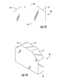
- FIGS. 13 and 14 are plan and perspective views, respectively, of one mirror operable with the retroreflector of FIG. 11
- FIG. 15 is a diagrammatical illustration of the light beam brush according to the teachings of the present invention illustrating an embodiment providing the incident and reflected beams projected in the same direction as opposed to opposite directions as illustrated in FIG. 11 ;
- a light beam brush 10 comprising a first lens 12 positioned for receiving a light beam 14 propagating along a first beam axis 16 .
- the light beam is a laser beam emitted from a laser as a light beam source 18 as a collimated beam of light.
- a retroreflector 20 includes first and second reflective surface 22 , 24 .
- the first reflective surface 22 is positioned for receiving the light beam 14 transmitted from the first lens 12 and redirecting the beam onto the second reflective surface 24 .
- a controller is operable with the retroreflector 20 for controlling an angle of rotation 38 of the first and second reflective surfaces 22 , 24 about the axis of rotation 26 and thus controlling a path length change 40 of the beam between the first and second lenses 12 , 28 .
- the angle of rotation 38 about the axis of rotation 26 and thus the path length change 40 is selected for providing a desired focus or divergence of the reflected beam transmitted through the second lens 28 .
- the reflective surfaces 22 , 24 may be surfaces of a prism 50 .
- the first reflective surface 22 may form an acute angle 52 or an obtuse angle 54 with the second reflective surface 24 , as illustrated with reference to FIGS. 3 and 4 , respectively.
- various reflective surface configurations, shapes and beam angles incident upon this selected surfaces may be employed, as illustrated with reference to FIGS. 5 , 6 and 7 , without departing from the teachings of the present invention.
- the first beam axis 16 is parallel to the second beam axis 32 , it may be desired to have them orthogonal to each other, as provided by the embodiments illustrated in FIGS. 3 and 4 , by way of non-limiting example.
- one known system is based on principle of creating a Newtonian telescope, and changing the path length through the telescope.
- Such a system includes a pair of lenses with positive focal length. Moving one lens toward the other results in an increase of divergence of the output beam, which is a desirable function when the system is used for laser display applications. Conversely, moving one lens away from the other will result in a focusing the output beam, which is a desirable function for laser marking and cutting operations.
- the distance between the two lenses will determine the degree of divergence increase or focusing.
- the two lenses can be placed at a distance equal to the sum of the focal lengths of the lenses.
- FIG. 8 illustrates a path as being straight through the pair of lenses.
- this path may be folded, by employing the use of a retroreflector, as illustrated with reference to FIG. 9 .
- the retroreflector includes a pair of mirrors, usually arranged at a 90-degree angle, so that an incoming light beam is reflected back toward an originating light beam direction.
- the retroreflector When the retro-reflector is employed as illustrated with continued reference to FIG. 9 , and now to FIG. 10 , the retroreflector may be moved in a linear fashion to affect the path length between the two lenses. This accomplishes the same result as moving the lenses themselves. While the embodiment of FIG. 10 is capable of changing the divergence or focus of an incoming light beam, there are challenges that create problems with linearly moving lenses and related structures. One major challenge is that an off-the-shelf actuator typically desired for use is not currently available for providing the degree of speed and precision typically required for demanding applications such as laser displays.
- the teachings of the present invention as above initially described may be operable using a limited-rotation rotary actuator such as a galvanometer-based optical scanner, along with the retroreflector selectively positioned to achieve divergence increases and focus changing as required for the demanding display and laser marking/cutting applications.
- a limited-rotation rotary actuator such as a galvanometer-based optical scanner
- the retroreflector selectively positioned to achieve divergence increases and focus changing as required for the demanding display and laser marking/cutting applications.
- FIG. 11 wherein the light beam brush 10 includes the retroreflector 20 formed using a base 56 rotatable about the axis of rotation 26 .
- a first mirror 58 is mounted on the base 56 and aligned at a first alignment 60 .
- the first mirror 58 includes the first reflective surface 22 above described with reference to FIG. 1 .
- a second mirror 62 is mounted on the base 56 and spaced at a distance 64 from the first mirror 58 .
- the space 64 between mirrors 58 , 62 may be preselected to accommodate a desired path length change 40 .
- the second mirror 62 is affixed to the base 56 and aligned at a second alignment 66 orientated orthogonal to the first alignment 60 .
- the second mirror includes the second reflective surface 24 above described with reference to FIG. 1 .
- the first and second mirrors 58 , 62 are generally rectangular in shape. However, to optimize weight and inertia as typically desired in laser scanning systems, each of the mirrors have their rectangular shapes including a center top portion 70 parallel to a bottom portion 72 and undercut 74 on top left and right sides, as illustrated with reference to FIGS. 13 and 14 .
- the light beam 14 is transmitted in one direction 76 along the first beam axis 16 and the reflected beam 30 is transmitted in an opposite direction 78 along the second beam axis 32 , with the second beam axis parallel to the first beam axis.
- One desirable use of the beam brush 10 is the value added when employed in a laser scanning system 90 illustrated, by way of example, with reference to FIG. 16 .
- An X-Y scanner 92 may be located downstream the second lens 28 for receiving the light beam 30 having focus or divergent characteristics.
- the incoming light beam 14 passes through the first lens 12 , then onto the first retroreflector mirror 58 , then onto the second retroreflector mirror 62 , then through the second lens 28 , as above described, and then onto an X-axis mirror 94 for deflection.
- the beam 30 is reflected from the X-axis mirror 94 to the Y-axis mirror 96 where it is then projected outward onto the target 34 which may include a projection surface or work piece.
- the retroreflector may be arranged in a Z-axis to provide X, Y and Z scanning, thus providing a Z-axis focusing beam brush.
- appropriate lenses may be approximately 12 mm focal length acromat lenses, and the galvanometer-based optical scanner used as the rotary actuator may be a low-inertia type, such as the model Saturn 5 from ScannerMAX.
- the controller 36 may be operable for transmitting a signal 98 to the X-Y scanner 92 during the controlling of the angle of rotation 38 of the retroreflector 20 for scanning action compensation, as desired.
- the collimated laser beam typically has a low divergence such that a beam diameter is generally maintained.
- the teachings of the present invention provide a desired control over such a laser beam.
- the controller 36 may comprise processing software for transmitting operational commands 100 to the laser source, thus having the system 100 fully controlling a performance of a laser show, by way of example.
- the incoming light beam 14 passes through the first lens 12 and is directed toward the first mirror 58 , which is part of the retroreflector 20 .
- the first mirror 58 reflects the light beam 14 at a 90-degree angle toward the second mirror 62 of the retroreflector 20 .
- the second mirror 62 then reflects that light beam at another 90-degree angle toward the second lens 28 .
- the reflected outgoing beam 30 emanates from the second lens either diverged, focused, or unchanged, depending on the orientation (position, rotation, and thus distance) of the retroreflector from the first lens and the second lenses.
- the command signal is sent to the beam brush scanner 84 (a rotary actuator) onto which the retroreflector assembly is attached.
- the retroreflector 20 whose pair of mirrors 58 , 62 is arranged at an angle of 90 degrees will always reflect the light beam back toward the original direction, regardless of the rotational orientation of the retroreflector 20 . Therefore, by placing the retroreflector 20 at a strategic axis of rotation 26 , it is possible to create the same path length change 40 as would happen if the retroreflector 20 were used with a linear actuator, as above described with reference to FIG. 10 .
- the axis of rotation 26 must be chosen as a tradeoff between the amount of path length change perceived by the pair of lenses 12 , 28 , the inertia of the retroreflector 20 , the amount of path length change 40 desired, and the resulting parasitic scanning.
- one desirable location for the axis of rotation 20 is proximate a location the where the beam 14 is reflected off of one of the mirrors 58 , as illustrated with reference again to FIGS. 1 , 11 and 12 .
- the retroreflector 20 can be made from aluminum or even plastic and thus it is very light and stiff, allowing high-speed positioning of the assembly, and thus high speed divergence or focus action.
- sample dimensions are presented illustrating one desirable orientation of the retroreflector mirrors.
Landscapes
- Physics & Mathematics (AREA)
- General Physics & Mathematics (AREA)
- Optics & Photonics (AREA)
- Mechanical Optical Scanning Systems (AREA)
Priority Applications (1)
| Application Number | Priority Date | Filing Date | Title |
|---|---|---|---|
| US14/182,469 US9244273B2 (en) | 2013-03-08 | 2014-02-18 | Z-axis focusing beam brush device and associated methods |
Applications Claiming Priority (2)
| Application Number | Priority Date | Filing Date | Title |
|---|---|---|---|
| US201361774763P | 2013-03-08 | 2013-03-08 | |
| US14/182,469 US9244273B2 (en) | 2013-03-08 | 2014-02-18 | Z-axis focusing beam brush device and associated methods |
Publications (2)
| Publication Number | Publication Date |
|---|---|
| US20140253994A1 US20140253994A1 (en) | 2014-09-11 |
| US9244273B2 true US9244273B2 (en) | 2016-01-26 |
Family
ID=50778536
Family Applications (1)
| Application Number | Title | Priority Date | Filing Date |
|---|---|---|---|
| US14/182,469 Active 2034-09-14 US9244273B2 (en) | 2013-03-08 | 2014-02-18 | Z-axis focusing beam brush device and associated methods |
Country Status (3)
| Country | Link |
|---|---|
| US (1) | US9244273B2 (de) |
| CN (1) | CN204028461U (de) |
| DE (1) | DE202014002094U1 (de) |
Cited By (1)
| Publication number | Priority date | Publication date | Assignee | Title |
|---|---|---|---|---|
| DE102023103707A1 (de) | 2023-02-15 | 2024-08-22 | Abberior Instruments Gmbh | Lichtmikroskop, fokussiereinrichtung und verfahren zum axialen verschieben einer fokusebene |
Families Citing this family (9)
| Publication number | Priority date | Publication date | Assignee | Title |
|---|---|---|---|---|
| US20160146939A1 (en) * | 2014-11-24 | 2016-05-26 | Apple Inc. | Multi-mirror scanning depth engine |
| US10247812B2 (en) | 2012-03-22 | 2019-04-02 | Apple Inc. | Multi-mirror scanning depth engine |
| CN104536134B (zh) * | 2014-12-30 | 2017-10-17 | 黄真理 | 一种探测光平行扫描设备 |
| US9798135B2 (en) | 2015-02-16 | 2017-10-24 | Apple Inc. | Hybrid MEMS scanning module |
| US10488652B2 (en) | 2016-09-21 | 2019-11-26 | Apple Inc. | Prism-based scanner |
| JP2020046455A (ja) * | 2018-09-14 | 2020-03-26 | キヤノン株式会社 | 光学装置及び加工装置 |
| CN114208006B (zh) | 2019-08-18 | 2024-10-29 | 苹果公司 | 具有电磁致动的力平衡微镜 |
| JP7547155B2 (ja) * | 2020-10-08 | 2024-09-09 | キヤノン株式会社 | 反射素子、光検出装置、及び光走査装置 |
| CN113238373B (zh) * | 2021-07-12 | 2021-10-12 | 沂普光电(天津)有限公司 | 一种激光扫描单元及激光打印机 |
Citations (5)
| Publication number | Priority date | Publication date | Assignee | Title |
|---|---|---|---|---|
| US5200797A (en) * | 1988-08-01 | 1993-04-06 | Deutsche Forschungsanstalt Fur Luft- Und Raumfahrt E.V. | Device for measuring the angle of rotation or of the angular position of a rotating object |
| US5621561A (en) | 1994-11-14 | 1997-04-15 | Neos Technologies, Inc. | Laser scanner incorporating variable focus mechanism for rapidly changing beam spot size |
| US6079833A (en) | 1999-02-17 | 2000-06-27 | Hughes-Jvc Technology Corporation | Laser imaging using a spatial light modulator |
| US6580560B1 (en) | 2002-02-01 | 2003-06-17 | William R. Benner, Jr. | Laser light projector having beam diffuser and associated methods |
| US8254045B1 (en) | 2009-06-05 | 2012-08-28 | Benner Jr William R | High-speed Z-axis focusing device and associated methods |
-
2014
- 2014-02-18 US US14/182,469 patent/US9244273B2/en active Active
- 2014-03-05 DE DE202014002094.9U patent/DE202014002094U1/de not_active Expired - Lifetime
- 2014-03-07 CN CN201420101575.8U patent/CN204028461U/zh not_active Expired - Lifetime
Patent Citations (5)
| Publication number | Priority date | Publication date | Assignee | Title |
|---|---|---|---|---|
| US5200797A (en) * | 1988-08-01 | 1993-04-06 | Deutsche Forschungsanstalt Fur Luft- Und Raumfahrt E.V. | Device for measuring the angle of rotation or of the angular position of a rotating object |
| US5621561A (en) | 1994-11-14 | 1997-04-15 | Neos Technologies, Inc. | Laser scanner incorporating variable focus mechanism for rapidly changing beam spot size |
| US6079833A (en) | 1999-02-17 | 2000-06-27 | Hughes-Jvc Technology Corporation | Laser imaging using a spatial light modulator |
| US6580560B1 (en) | 2002-02-01 | 2003-06-17 | William R. Benner, Jr. | Laser light projector having beam diffuser and associated methods |
| US8254045B1 (en) | 2009-06-05 | 2012-08-28 | Benner Jr William R | High-speed Z-axis focusing device and associated methods |
Cited By (1)
| Publication number | Priority date | Publication date | Assignee | Title |
|---|---|---|---|---|
| DE102023103707A1 (de) | 2023-02-15 | 2024-08-22 | Abberior Instruments Gmbh | Lichtmikroskop, fokussiereinrichtung und verfahren zum axialen verschieben einer fokusebene |
Also Published As
| Publication number | Publication date |
|---|---|
| DE202014002094U1 (de) | 2014-05-02 |
| US20140253994A1 (en) | 2014-09-11 |
| CN204028461U (zh) | 2014-12-17 |
Similar Documents
| Publication | Publication Date | Title |
|---|---|---|
| US9244273B2 (en) | Z-axis focusing beam brush device and associated methods | |
| JP2007521518A5 (de) | ||
| JP6680773B2 (ja) | 平行オフセット部を備えたレーザ加工装置 | |
| CN112068309B (zh) | 一种含双抛物面镜动态聚焦模块的三维扫描系统 | |
| CN107850773A (zh) | 光束导向器 | |
| DE112013006119T5 (de) | Optische Abtasteinrichtung und Projektor | |
| US20180157006A1 (en) | Laser processing apparatus | |
| US12416804B1 (en) | Kaleidoscopic laser beam projection system | |
| JP5499502B2 (ja) | 光学装置 | |
| CN108663817B (zh) | 能够改变光束的传播方向的光学装置和包括该装置的系统 | |
| US20200088979A1 (en) | Optical apparatus | |
| US20170285327A1 (en) | Method for controlling position of a linear mems mirror with variable resolution and/or light intensity | |
| JP5196582B2 (ja) | 可動鏡機構 | |
| JP2022186801A (ja) | 光走査装置 | |
| JP2018189521A (ja) | レーザレーダ装置 | |
| US20090051995A1 (en) | Linear Optical Scanner | |
| US7463394B2 (en) | Linear optical scanner | |
| US9195061B1 (en) | Scanning mirror system and associated methods | |
| KR101633988B1 (ko) | 스캐닝 마이크로미러 | |
| US20190283180A1 (en) | Laser printing with device that includes voice coil-activated lens | |
| CN111487764B (zh) | 一种基于抛物面反射镜折叠光路的激光动态聚焦系统 | |
| CN210072202U (zh) | 一种光学层析成像扫描装置 | |
| JPH05228673A (ja) | レ−ザ−加工装置 | |
| US6115167A (en) | Optical actuator for directing an incident light beam onto a fixed surface external to the actuator | |
| Montagu | Two-axis beam-steering systems: TABS |
Legal Events
| Date | Code | Title | Description |
|---|---|---|---|
| STCF | Information on status: patent grant |
Free format text: PATENTED CASE |
|
| MAFP | Maintenance fee payment |
Free format text: PAYMENT OF MAINTENANCE FEE, 4TH YR, SMALL ENTITY (ORIGINAL EVENT CODE: M2551); ENTITY STATUS OF PATENT OWNER: SMALL ENTITY Year of fee payment: 4 |
|
| MAFP | Maintenance fee payment |
Free format text: PAYMENT OF MAINTENANCE FEE, 8TH YR, SMALL ENTITY (ORIGINAL EVENT CODE: M2552); ENTITY STATUS OF PATENT OWNER: SMALL ENTITY Year of fee payment: 8 |