US9242596B2 - Adjustable downlighter - Google Patents
Adjustable downlighter Download PDFInfo
- Publication number
- US9242596B2 US9242596B2 US14/353,294 US201214353294A US9242596B2 US 9242596 B2 US9242596 B2 US 9242596B2 US 201214353294 A US201214353294 A US 201214353294A US 9242596 B2 US9242596 B2 US 9242596B2
- Authority
- US
- United States
- Prior art keywords
- spread
- light
- lamp
- downlight
- vehicle
- Prior art date
- Legal status (The legal status is an assumption and is not a legal conclusion. Google has not performed a legal analysis and makes no representation as to the accuracy of the status listed.)
- Expired - Fee Related
Links
- 239000003550 marker Substances 0.000 claims abstract description 32
- 230000000007 visual effect Effects 0.000 claims description 7
- 238000005286 illumination Methods 0.000 description 9
- 238000009434 installation Methods 0.000 description 7
- 230000008901 benefit Effects 0.000 description 2
- 230000000981 bystander Effects 0.000 description 2
- 238000010276 construction Methods 0.000 description 2
- 230000000694 effects Effects 0.000 description 2
- 238000005516 engineering process Methods 0.000 description 2
- 230000002411 adverse Effects 0.000 description 1
- 238000003491 array Methods 0.000 description 1
- 230000000295 complement effect Effects 0.000 description 1
- 238000002474 experimental method Methods 0.000 description 1
- 230000004438 eyesight Effects 0.000 description 1
- 239000004744 fabric Substances 0.000 description 1
- 230000006870 function Effects 0.000 description 1
- 230000004313 glare Effects 0.000 description 1
- 230000005484 gravity Effects 0.000 description 1
- 239000011159 matrix material Substances 0.000 description 1
- 238000000034 method Methods 0.000 description 1
- 230000008447 perception Effects 0.000 description 1
- 230000002093 peripheral effect Effects 0.000 description 1
- 230000001105 regulatory effect Effects 0.000 description 1
- 239000007921 spray Substances 0.000 description 1
- 239000013589 supplement Substances 0.000 description 1
- 230000007704 transition Effects 0.000 description 1
- WFKWXMTUELFFGS-UHFFFAOYSA-N tungsten Chemical compound [W] WFKWXMTUELFFGS-UHFFFAOYSA-N 0.000 description 1
- 229910052721 tungsten Inorganic materials 0.000 description 1
- 239000010937 tungsten Substances 0.000 description 1
Images


Classifications
-
- B—PERFORMING OPERATIONS; TRANSPORTING
- B60—VEHICLES IN GENERAL
- B60Q—ARRANGEMENT OF SIGNALLING OR LIGHTING DEVICES, THE MOUNTING OR SUPPORTING THEREOF OR CIRCUITS THEREFOR, FOR VEHICLES IN GENERAL
- B60Q1/00—Arrangement of optical signalling or lighting devices, the mounting or supporting thereof or circuits therefor
- B60Q1/26—Arrangement of optical signalling or lighting devices, the mounting or supporting thereof or circuits therefor the devices being primarily intended to indicate the vehicle, or parts thereof, or to give signals, to other traffic
- B60Q1/48—Arrangement of optical signalling or lighting devices, the mounting or supporting thereof or circuits therefor the devices being primarily intended to indicate the vehicle, or parts thereof, or to give signals, to other traffic for parking purposes
-
- B—PERFORMING OPERATIONS; TRANSPORTING
- B60—VEHICLES IN GENERAL
- B60Q—ARRANGEMENT OF SIGNALLING OR LIGHTING DEVICES, THE MOUNTING OR SUPPORTING THEREOF OR CIRCUITS THEREFOR, FOR VEHICLES IN GENERAL
- B60Q1/00—Arrangement of optical signalling or lighting devices, the mounting or supporting thereof or circuits therefor
- B60Q1/26—Arrangement of optical signalling or lighting devices, the mounting or supporting thereof or circuits therefor the devices being primarily intended to indicate the vehicle, or parts thereof, or to give signals, to other traffic
- B60Q1/32—Arrangement of optical signalling or lighting devices, the mounting or supporting thereof or circuits therefor the devices being primarily intended to indicate the vehicle, or parts thereof, or to give signals, to other traffic for indicating vehicle sides, e.g. clearance lights
-
- B—PERFORMING OPERATIONS; TRANSPORTING
- B60—VEHICLES IN GENERAL
- B60Q—ARRANGEMENT OF SIGNALLING OR LIGHTING DEVICES, THE MOUNTING OR SUPPORTING THEREOF OR CIRCUITS THEREFOR, FOR VEHICLES IN GENERAL
- B60Q1/00—Arrangement of optical signalling or lighting devices, the mounting or supporting thereof or circuits therefor
- B60Q1/02—Arrangement of optical signalling or lighting devices, the mounting or supporting thereof or circuits therefor the devices being primarily intended to illuminate the way ahead or to illuminate other areas of way or environments
- B60Q1/24—Arrangement of optical signalling or lighting devices, the mounting or supporting thereof or circuits therefor the devices being primarily intended to illuminate the way ahead or to illuminate other areas of way or environments for lighting other areas than only the way ahead
- B60Q1/247—Arrangement of optical signalling or lighting devices, the mounting or supporting thereof or circuits therefor the devices being primarily intended to illuminate the way ahead or to illuminate other areas of way or environments for lighting other areas than only the way ahead for illuminating the close surroundings of the vehicle, e.g. to facilitate entry or exit
-
- B—PERFORMING OPERATIONS; TRANSPORTING
- B60—VEHICLES IN GENERAL
- B60Q—ARRANGEMENT OF SIGNALLING OR LIGHTING DEVICES, THE MOUNTING OR SUPPORTING THEREOF OR CIRCUITS THEREFOR, FOR VEHICLES IN GENERAL
- B60Q1/00—Arrangement of optical signalling or lighting devices, the mounting or supporting thereof or circuits therefor
- B60Q1/26—Arrangement of optical signalling or lighting devices, the mounting or supporting thereof or circuits therefor the devices being primarily intended to indicate the vehicle, or parts thereof, or to give signals, to other traffic
- B60Q1/48—Arrangement of optical signalling or lighting devices, the mounting or supporting thereof or circuits therefor the devices being primarily intended to indicate the vehicle, or parts thereof, or to give signals, to other traffic for parking purposes
- B60Q1/484—Arrangement of optical signalling or lighting devices, the mounting or supporting thereof or circuits therefor the devices being primarily intended to indicate the vehicle, or parts thereof, or to give signals, to other traffic for parking purposes for showing outline of vehicle
Definitions
- This invention relates to vehicle lighting and is particularly but not exclusively concerned with visual marking and delineation of a freight or goods road vehicle or trailer, for the benefit of a vehicle driver and drivers of other vehicles, pedestrians or remote bystanders.
- Driver needs are not the same as those of others and so may not be best served by the same light format. Marking to a vehicle sides is one consideration.
- vehicle is used herein to embrace a self-propelled truck or towed or towable trailer, or indeed any other movable body to which a downlight may be fitted.
- Front mounted headlights give illumination to the front and in some respects a wider forward field of vision beyond that of the vehicle width, at least when looking and driving forward.
- Rear mounted reversing lights are of little or no use to the driver in judging width, since the area immediately behind the vehicle is not visible.
- Fixed side marker lights and reflectors are common for freight vehicles and trailers and in some jurisdictions are required by statute. The prime intention of these is to provide a visual indication of the presence of vehicle when viewed from afar by other road users. Daylight running lights or provision within night lighting are also known, but generally to the front.
- U.S. Pat. No. 5,209,559 Ruppel teaches a fixed down light or illumination to the rear. These are limited and inflexible in installation and use, and risk shining distracting and disturbing light sideways, which poses a hazard and breach of regulations. A non-dazzling downlight adaptable to different vehicles and installation constraints is desirable, but poses a challenge addressed by some aspects of the present invention.
- adjustable support internal reflector or external lens or diffuser
- Such downlighting provides illumination to an area around the side of a vehicle and/or trailer, so that a driver can see what is going on around them, including the presence of pedestrians or cyclists along the perimeter and adjacent to the sides. Increased visible presence of the vehicle is also offered to other road users from the side. This is imperative, especially when maneuvering/driving in poor visibility conditions.
- a light is fixed rigidly to the body/chassis of a vehicle/trailer and the light source, which may be, inter alia, an LED or luminescent bulb and its associated light carrier may be pivoted/rotated about a vertical axis in order to alter the angle of incidence between the light source and the plane of the road surface.
- the light source which may be, inter alia, an LED or luminescent bulb and its associated light carrier may be pivoted/rotated about a vertical axis in order to alter the angle of incidence between the light source and the plane of the road surface.
- a light and housing may be fitted at a certain vertical distance from the road surface, say, by a non-rotational housing, and then the illuminating means and carrier is pivoted/rotated to the desired angle for the avoidance of dazzling and so offering an illuminated area adjacent to the side of the vehicle/trailer.
- the illuminating light carrier can be adjusted in to various different angles, offering a selection of vertical downward light spreads over various heights of fitment. This method of light adjustment ensures that the device does not alter in physical size, which could affect the overall vehicle dimensions if fitted at the edge of the vehicle/trailer (Construction and Use Regulations in all Territories). Once fitted and the required angle has been set, the device does not require any further adjustment.
- the side marker light is contained within a separate compartment to that of the adjustable down light.
- a combined fixed orientation side marker light and adjustable orientation downlight can be adopted, again sharing a wiring loom. This could usefully have a compact format, even with (internal) beam adjustment provision.
- a split casing, with sub-divided side marker and downlighter portions, could allow mutual angular adjustment.
- a coloured lens may be fitted to the downlight to complement that of the side marker light, which in the UK is amber by legislation. That said, in principle, subject to prevailing regulatory constraints, other single or multi-colour down lighting might be contemplated where local legislation allows. Thus, say, a banded or continuum gradient colour and/or gradient single colour or monochrome light intensity band downlight might be adopted to indicate distance from a vehicle footprint.
- a downlight can usefully delineate by reflection from the ground. Local general ground area illumination immediately adjacent a vehicle margins by a downlight is key. Light patterns could also be contemplated better to convey spatial reference. Thus, say, a matrix or grid pattern of lines or dots could assist this.
- a reflector such as with adjustable panels, could play a role in beam spread determination.
- a front lens or diffuser such as a Fresnel lens with serration or ridge patterns, could contribute to this and to anti-glare measures.
- a side-mounted downlight also has advantages for other road users in making the vehicle more visually prominent to others.
- a downlight usefully supplements a side marker light or reflector.
- a ‘passive’ side reflector could be combined with some self-illumination to serve a side marker role, without producing disturbing glare to others. Thus unwanted stray light could be contained or suppressed, say by internal reflection or re-direction. The marker would then ‘glow’ without shining unduly outward.
- an upper beam spread margin set for a loaded vehicle may be to high when the vehicle is unloaded.
- Adjustment might use spirit-level, gravity see-saw pendulum, or gyroscopic horizontal reference as a threshold to limit or depress upper beam margin spread.
- An automated dynamic beam adjustment such as a self-balanced mount, could be contemplated.
- an installation rig could be contrived, by which all lights on the same side could be set to the same downlight beam spread margins and orientation for consistency and harmony in visual stance and disposition.
- Beam spread and orientation could be achieved with a multi-faceted reflector panels, some adjustable. Similarly, with a multi-panel front and peripheral lens portions, alone or in co-operation with the reflectors.
- One measure is an adjustable lamp casing mounting. Another measure is adjustable internal reflectors. A further measure is an adjustable internal lamp mounting.
- a second light beam portion with an internal reflector and external lens configured as a downlight
- a common or shared light source could be used for both light beam portions, such as with filters to adjust intensity and/or colour.
- a multi-element bulb could be used selectively to provide different light outputs per element.
- a similar effect may be achieved with apportioned LED clusters in different groupings and sub-groups.
- discrete pin-point light sources with appropriate output and colour could be employed.
- Independent beam setting such as of orientation, direction and spread, may be achieved for different beams upon a shared mounting and/or within a common housing.
- a side and downlight be used as so-called daylight running lights, with appropriate adjustment in light output to be visibility in daylight.
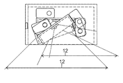
- FIG. 1 shows the fitment of a downlight 10 along the side edge but within the confines of a semi-trailer 13 .
- FIG. 2 shows the horizontal light spread 11 from the downlight 10 when fitted high up on the chassis of a semi-trailer ( 13 ).
- FIG. 3 shows from the rear, the vertical angle of the light spread 12 from the downlight 10 , covering the area adjacent to the sides, when fitted high up on the chassis of a semi-trailer ( 13 ) but within the confines of the vehicle/trailer.
- FIG. 4 shows from the rear, the shallower vertical angle of the light outward spread 12 a from the downlight 10 by tilting the light assembly 20 to a different greater angle, offering a shallower angle of light spread 12 a , when fitted lower to the ground on a caravan 14 but within the confines of the caravan.
- FIG. 5 shows the fitment of the downlight 10 above the wheels 8 but within the confines of a semi-trailer 13 .
- FIG. 6 shows the horizontal light spread 11 from the downlight 10 when fitted above the wheels 8 , but within the confines of a semi-trailer 13 .
- FIG. 7 shows from the rear, the vertical angle light spread 12 from the downlight 10 when fitted above the wheels 8 , but within the confines of a semi-trailer 13 .
- FIG. 8 shows a front elevation of the downlight 10 , highlighting the location of a separate side marker light compartment 9 and the location of the angular pivot holes; including the locations of holes ( 4 a 1 ) for a pivot pin (not shown), allowing a location pin to be inserted into 4 b or 4 c to locate two different angles, with a third angle being introduced by a location pin 4 c remaining in position ( 4 c ) while the pivoting pin ( 4 a 1 ) is relocated into position 4 a 2 .
- FIG. 9 shows a plan view of the downlight 10 of FIG. 8 with pivot holes 4 a 1 , 4 a 2 , 4 b , 4 c highlighting the location of the separate marker light compartment ( 9 ).
- FIG. 10 shows a right end elevation of the downlight 10 highlighting the location of the separate side marker light compartment 9 .
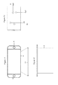
- FIG. 11 shows a front elevation of the downlight 10 without a side marker light compartment.
- FIG. 12 shows a plan view of the downlight 10 without a side marker light compartment.
- FIG. 13 shows a right end elevation of a downlight 10 without the side marker light compartment, and the location of mounting and adjustment holes 4 a 1 , 4 a 4 , 4 b , 4 c for angular pivoting.
- FIG. 14 shows a plan view of an LED gear tray 1 for a downlight 10 with the position of an LED chip ( 7 ) and the holes 5 for securing the top bracket ( 2 ) which holds the pivoting/location pin and the holes ( 6 ) for the securing of the front bracket ( 2 ) which holds the pivoting/location pin.
- FIG. 15 shows a front view of an LED gear tray 1 of FIG. 14 .
- FIG. 16 shows a right end elevation of a LED gear tray 1 of FIGS. 14 and 15 .
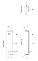
- FIG. 17 shows a plan view of a mounting and securing bracket 2 and the holes ( 4 ) to fix the bracket ( 2 ) to the top of the LED gear tray ( 1 ) with the pivoting/location pin holes ( 3 )
- FIG. 18 shows a front view of the mounting and securing bracket of FIG. 17 .
- FIG. 19 shows a right end elevation of the mounting and securing bracket of FIG. 17 and the location of the hole 3 for a pivot and/or location pin.
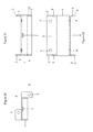
- FIG. 20 shows a right end elevation of an angularly adjustable light assembly, which is made up of the LED gear tray ( 1 ) 2 off securing brackets ( 2 ) and the LED chip ( 7 ).
- FIG. 21 shows a front elevation of the angularly adjustable light assembly of FIG. 20 .
- FIG. 22 shows a top view of the angularly adjustable light assembly of FIG. 20 .
- FIG. 23 shows a combination of FIGS. 13 and 20 using pivot hole 4 a 1 and location hole 4 b , with a vertical angular light spread 12 of 45°.
- FIG. 24 shows a combination of FIGS. 13 and 20 angled to give off a shallower vertical light spread, by using pivot hole 4 a 1 and location hole 4 c , for a vertical angular light spread 12 of 25°.
- FIG. 25 shows a combination of FIGS. 13 and 20 angled to give an even more shallow vertical light spread, due to it being fitted low to the ground, by keeping a pin located in 4 c and moving a pivot pin from 4 a 1 up to a new location of 4 a 2 , for a vertical angular light spread 12 of 10°.
- FIG. 26 shows a combination of FIGS. 13 and 20 in three different alternative locations, while staying within the confines of the outer case of a downlight 10 , and which in turn remains within the confines of the vehicle/trailer/caravan, offering three different vertical locations and angular dispositions.
- FIG. 27 shows a close-up from the rear of a downlight 10 fitted along a side and above a wheel, but within the confines of the semi-trailer 13 , with a light spread 12 in a vertical plane.
- FIG. 28 shows a close-up of a side of a semi-trailer wheel 8 with a downlight 10 fitted above it, but within the confines of the bodywork and a light spread 11 in a horizontal plane highlighting the wheel position.
- a series of downlights 10 are fitted, in a mutually co-operative linear array, to the lower body edge over the entire longitudinal span of the vehicle or trailer, as shown. They are conveniently co-located with side marker lights or reflectors, but are not restricted to that. Locations can include between the wheels 8 , for which a more compact light format may be adopted given restricted space around spray shields.
- FIG. 2 shows the individual down light beam spread or illuminated ground foot print 11 longitudinally with some overlap.
- FIG. 3 shows the outward lateral downlight beam spread 12 , with an abrupt or sharp vertical linear cut-off directly underneath, although some inward spill or intrusion could be admitted.
- Either or both longitudinal and lateral beam spread can be determined by downlight housing and reflector configuration and by down light mounting direction or orientation.
- the higher set chassis or body dictates a high downlight mounting position and a wider outward beam spread for a given lamp reflector.
- FIG. 4 shows a lower set trailer such as a caravan than FIG. 3 with corresponding lower set downlights 10 and concomitant wider outward ground spread 12 a .
- FIGS. 5 , 6 and 7 address a particular downlight 10 disposition in relation to vehicle wheels 8 . Longitudinal alignment of wheels 8 and downlights 10 is adopted with a marginal edge longitudinal beam spread overlap 11 and outward splay 12 .
- FIGS. 8 , 9 and 10 show lamp body mounting detail, with index and location holes 4 a , 4 b , 4 c and 5 .
- FIGS. 11 , 12 and 13 show another mounting view, with location holes 4 a 1 , 4 a 2 , 4 b , 4 c and 5 .
- FIGS. 14 , 15 and 16 show further mounting views with location holes 5 , 6 and light source 7 .
- FIGS. 17 , 18 and 19 show a downlighter lamp body mounting bracket 2 with location holes 3 .
- FIGS. 20 , 21 and 22 show a bracket for combined side marker light and downlight mounting, with a light source index 7 .
- FIGS. 23 , 24 , 25 and 26 show various downlight mounting bracket positions with attendant beam spread 12 from a light source 7 , with use of index and location mounting holes to achieve certain pre-set downlight dispositions and orientations.
- FIGS. 27 and 28 show downlight 10 disposition at the lower corner edge of a vehicle body 13 adjacent the upper margins of a vehicle wheel, 8 using a compact format downlight body, to achieve a lateral outward beam spread 12 and a longitudinal beam spread 11 .
- An individual downlight 10 usefully has provision for adjustment of the direction, orientation and horizontal and vertical spread of an output light beam. It is important to limit the upper margins or limit of a beam spread, so as not to shine sideways at too high an angle, and thereby risk distracting or disturbing a bystander or driver of another vehicle. That is an overall beam constraint is imposed. This can be achieved with a mounting and/or with internal reflectors and a cover lens. With a higher light position the beam upper margin is higher for a given beam direction or orientation, so there is likely a need to point the beam more downward to compensate.
- the lower limit of the beam spread is less critical as the worst case scenario would simply be to direct light wastefully directly under the vehicle; although even there a ground light pool can contribute to overall vehicle prominence, as can any area bathed in light which meets regulations and does not disturb or distract others. For a driver it is the outward spread of a ground pool of light which gives a useful visual reference of position and vehicle planform or footprint width or span and length.
- a lamp with an adjustable spread is likely to be more expensive to construct, so a minimal adjustment to the lamp body mounting to set an upper beam margin limit would be desirable.
- Supplementary measures such as movable, segmented or adjustable curvature, reflector panels behind and alongside the light source would offer greater beam spread and directional control, albeit at more expense and time consuming setting.
- a series of down lights are spaced (evenly) along the sides of a vehicle or trailer, generally at positions corresponding to an existing fixed side marker light and reflector.
- a smaller version is configured to fit over the vehicle wheels where more severe space limitations arise than elsewhere along the vehicle body.
- a downlight can be fitted closed to or flush with a trailer bottom edge, so as not to increase overall trailer width, and may be inset somewhat under the vehicle body without undue limitation of the laterally outward spread of the pool of light on the ground.
- mounting holes in a downlight casing or housing can help with setting an appropriate housing disposition and angular orientation.
- a pivot mounting hole could serve with one or more companion angular position setting holes on the same side, for ease of reference and setting, and to allow resetting for different fitting heights. Once set, it is desirable to have secure fitting to ensure the downlight orientation and light beam upper margin does not change adversely such as through vehicle vibration.
- the housing (horizontal) pivot axis can be at, juxtaposed with or offset from, an internal light source, such as tungsten filament bulb or LED.
- an internal light source such as tungsten filament bulb or LED.
- any internal pivoted or adjustable profile reflector panels and/or outer lens diffuser panels can be at, juxtaposed with or offset from, an internal light source, such as tungsten filament bulb or LED.
- the housing can have internal or external baffles, shields or deflectors against unwanted light output. Certain parts of the housing body itself can serve this function or role.
- Internal reflectors admit of fixed or movable mounting. Similarly with internal baffles, masks or shutters, including the casing or housing side walls. Reflectors can determine a beam focus or spread, so could have a continuous 3D curvature to that end.
- An example overall downlight beam spread viewed from the side would be some 75 degrees, constrained or bounded by the housing or internal reflection body. Of this overall 75 degrees, some 45 degrees could spread forward of a vertical axis through the light source and some 30 degrees rearward of that axis. A removable shutter could further curtail the rearward spread to some 15 degrees. A typical projected light output of some 500 Candelas could be employed.
- a plan view of beam spread onto the ground could be a rectangular foot print with a housing rear edge boundary at one side, and sharp rectangular cut-off corners or curved corner transitions.
- a removable reflector shield fitted in a housing body slot could be used to limit or truncate the front or rear beam spread outer margins.
- a some 90 degree overall beam spread in a vertical plane bounded by inclined opposite housing side walls could provide sufficient longitudinal span to reach or overlap that of a successive adjacent downlight.
- the light output could be adjusted accordingly, say with a higher output of 700-1200 Candelas for a directly downward pointing housing or reflector, giving a sideways ground spread of 700-1200. This could reduce to 450-700 Candelas for a lamp body or reflector tilted rearward by some 15 degrees with a forward ground spread of 780-1212.
- Variants include multiple downlights or light sources fitted side-by-side in a line, within a shared elongate housing, for a more concentrated and delineated light coverage below and adjacent a vehicle, whether truck, bus, recreational vehicle, car or trailer.
- a demountable downlight say fitted upon a quick-release bracket, or an extendible swivel mount, with an umbilical power cord and/or internal rechargeable battery pack might serve as a emergency warning or illumination lamp, with optional switched flashing beacon mode, accessible from the side of a vehicle.
- a downlight admits of far wider use than vehicles.
- reflectors and lights on clothing are known a downlight carried by, secured to or integrated with a garment fabric could be deployed to create a personal pool of light, useful for pedestrian visibility and as a supplementary self-illumination security measure.
- the considerations of beam orientation and spread can be adapted accordingly.
- beam intensity and power consumption for a portable power source can be adapted accordingly.
Landscapes
- Engineering & Computer Science (AREA)
- Mechanical Engineering (AREA)
- Transportation (AREA)
- Lighting Device Outwards From Vehicle And Optical Signal (AREA)
- Non-Portable Lighting Devices Or Systems Thereof (AREA)
Abstract
Description
Claims (10)
Applications Claiming Priority (5)
| Application Number | Priority Date | Filing Date | Title |
|---|---|---|---|
| GBGB1118248.2A GB201118248D0 (en) | 2011-10-23 | 2011-10-23 | Vehicle side marker and downward light |
| GB1118248.2 | 2011-10-23 | ||
| GB1200433.9 | 2012-01-12 | ||
| GB1200433.9A GB2488862B (en) | 2011-10-23 | 2012-01-12 | Vehicle/trailer side marker light with a vertically adjustable angular down light |
| PCT/GB2012/052605 WO2013061036A1 (en) | 2011-10-23 | 2012-10-19 | Adjustable downlighter |
Publications (2)
| Publication Number | Publication Date |
|---|---|
| US20140313756A1 US20140313756A1 (en) | 2014-10-23 |
| US9242596B2 true US9242596B2 (en) | 2016-01-26 |
Family
ID=45373261
Family Applications (1)
| Application Number | Title | Priority Date | Filing Date |
|---|---|---|---|
| US14/353,294 Expired - Fee Related US9242596B2 (en) | 2011-10-23 | 2012-10-19 | Adjustable downlighter |
Country Status (4)
| Country | Link |
|---|---|
| US (1) | US9242596B2 (en) |
| EP (1) | EP2768700A1 (en) |
| GB (4) | GB201118248D0 (en) |
| WO (1) | WO2013061036A1 (en) |
Cited By (4)
| Publication number | Priority date | Publication date | Assignee | Title |
|---|---|---|---|---|
| US20160370588A1 (en) * | 2013-12-17 | 2016-12-22 | Marsupial Holdings Inc. | Integrated MicroOptic Imager, Processor, and Display |
| US9566901B1 (en) | 2016-05-03 | 2017-02-14 | Toyota Motor Engineering & Manufacturing North America, Inc. | Vehicle indicating side marker lighting systems |
| US10220768B2 (en) * | 2017-07-11 | 2019-03-05 | Paccar Inc | Platooning light fence system and method |
| US12209723B1 (en) | 2024-05-20 | 2025-01-28 | Honda Motor Co., Ltd. | Accent lighting assembly for a utility vehicle |
Families Citing this family (7)
| Publication number | Priority date | Publication date | Assignee | Title |
|---|---|---|---|---|
| DE102014213864A1 (en) | 2014-07-16 | 2016-01-21 | Bombardier Transportation Gmbh | Device and method for positioning an auxiliary device and rail vehicle |
| US9669756B2 (en) | 2014-09-29 | 2017-06-06 | Nissan North America, Inc. | Under vehicle illumination |
| US11229103B2 (en) * | 2018-05-09 | 2022-01-18 | Chris Bart H | Supplemental exterior lighting system for recreational vehicles |
| DE102018118314A1 (en) * | 2018-07-30 | 2020-01-30 | HELLA GmbH & Co. KGaA | Marking device and vehicle trailer with the marking device |
| US11052818B2 (en) * | 2019-05-22 | 2021-07-06 | Ya-Chi Ching | Large vehicle turning safety warning apparatus |
| US11926257B2 (en) * | 2020-11-19 | 2024-03-12 | Ya-Chi Ching | Multi-lighting projection warning device for vehicle turning |
| US12319196B2 (en) * | 2022-12-20 | 2025-06-03 | Nissan North America, Inc. | Image projector |
Citations (21)
| Publication number | Priority date | Publication date | Assignee | Title |
|---|---|---|---|---|
| US1802958A (en) | 1929-11-13 | 1931-04-28 | Ravencroft Ralph Jay | Automobile road lighting |
| US1810216A (en) | 1929-02-15 | 1931-06-16 | Benneville Lloyd Singley | Vehicle light |
| GB453694A (en) | 1936-03-10 | 1936-09-16 | Harold James Shrapnel | Improvements in or connected with systems of road lighting from motor vehicles |
| US2193063A (en) | 1937-11-08 | 1940-03-12 | Walter M Dettweiler | Auxiliary safety lighting system for vehicles |
| US3457397A (en) | 1966-05-20 | 1969-07-22 | Marion E Tindall | Safety light |
| US5209559A (en) | 1991-12-04 | 1993-05-11 | Ruppel Raymond A | Trailer light system |
| US5430625A (en) * | 1994-02-14 | 1995-07-04 | Abarr; Larry D. | Illumination system for enhanced control of vehicles |
| JPH10211846A (en) | 1997-01-30 | 1998-08-11 | I P F Kk | Side lamp for vehicle |
| DE10058903A1 (en) | 2000-09-26 | 2002-04-11 | Brose Fahrzeugteile | Light arrangement for vehicle has light unit providing luminous area extending laterally to vehicle along vehicle compartment |
| WO2003027990A2 (en) | 2001-09-26 | 2003-04-03 | Grutze Glen A | Gobo projector for a vehicle |
| US6543917B1 (en) * | 2000-11-20 | 2003-04-08 | Peter Till | Vehicle position indicating device |
| US20030107900A1 (en) * | 2001-12-07 | 2003-06-12 | Ellison Thomas F. | Vehicle perimeter indicator |
| US20030174505A1 (en) * | 2002-03-14 | 2003-09-18 | Wainlight | Vehicle marking method, device, vehicle and adapted road |
| DE20312419U1 (en) | 2003-08-12 | 2003-10-16 | Hella KG Hueck & Co., 59557 Lippstadt | Side illuminating light for vehicles especially trucks has optical axis perpendicular to baseplate and illuminates both the side and beneath the vehicle |
| US20050068785A1 (en) * | 2003-09-29 | 2005-03-31 | Kazuo Takeda | Illuminating device for vehicle |
| WO2005123451A1 (en) | 2004-06-17 | 2005-12-29 | Williams Richelt G | Adjustable multi-function vehicle approach ground and object lighting equipment |
| DE102005029017A1 (en) | 2005-06-21 | 2006-09-21 | Daimlerchrysler Ag | Lighting device for commercial vehicle, has lighting unit with lighting characteristics that are adjustable such that lighting unit illuminates bottom portion of passenger entrance/exit area, vehicle surrounding and integrated workspace |
| US7175320B1 (en) | 2002-09-20 | 2007-02-13 | Lynn Emerson Burgess | Adjustable elevated light for transportation vehicles |
| DE102005050642A1 (en) | 2005-10-20 | 2007-04-26 | Franz-Josef Handwerker | Lighting unit for a vehicle has lights above the vehicle wheels to illuminate the street side of the wheels and the boundary region between the wheels and road |
| WO2010151209A1 (en) | 2009-06-23 | 2010-12-29 | Scania Cv Ab | Light device for a motor vehicle |
| US20120268960A1 (en) * | 2011-04-19 | 2012-10-25 | Kiser Lawrence E | Safety light for trailers |
-
2011
- 2011-10-23 GB GBGB1118248.2A patent/GB201118248D0/en not_active Ceased
-
2012
- 2012-01-12 GB GB1200433.9A patent/GB2488862B/en active Active
- 2012-10-19 GB GB1406900.9A patent/GB2509458A/en not_active Withdrawn
- 2012-10-19 GB GBGB1218854.6A patent/GB201218854D0/en not_active Ceased
- 2012-10-19 EP EP12799246.9A patent/EP2768700A1/en not_active Withdrawn
- 2012-10-19 WO PCT/GB2012/052605 patent/WO2013061036A1/en not_active Ceased
- 2012-10-19 US US14/353,294 patent/US9242596B2/en not_active Expired - Fee Related
Patent Citations (21)
| Publication number | Priority date | Publication date | Assignee | Title |
|---|---|---|---|---|
| US1810216A (en) | 1929-02-15 | 1931-06-16 | Benneville Lloyd Singley | Vehicle light |
| US1802958A (en) | 1929-11-13 | 1931-04-28 | Ravencroft Ralph Jay | Automobile road lighting |
| GB453694A (en) | 1936-03-10 | 1936-09-16 | Harold James Shrapnel | Improvements in or connected with systems of road lighting from motor vehicles |
| US2193063A (en) | 1937-11-08 | 1940-03-12 | Walter M Dettweiler | Auxiliary safety lighting system for vehicles |
| US3457397A (en) | 1966-05-20 | 1969-07-22 | Marion E Tindall | Safety light |
| US5209559A (en) | 1991-12-04 | 1993-05-11 | Ruppel Raymond A | Trailer light system |
| US5430625A (en) * | 1994-02-14 | 1995-07-04 | Abarr; Larry D. | Illumination system for enhanced control of vehicles |
| JPH10211846A (en) | 1997-01-30 | 1998-08-11 | I P F Kk | Side lamp for vehicle |
| DE10058903A1 (en) | 2000-09-26 | 2002-04-11 | Brose Fahrzeugteile | Light arrangement for vehicle has light unit providing luminous area extending laterally to vehicle along vehicle compartment |
| US6543917B1 (en) * | 2000-11-20 | 2003-04-08 | Peter Till | Vehicle position indicating device |
| WO2003027990A2 (en) | 2001-09-26 | 2003-04-03 | Grutze Glen A | Gobo projector for a vehicle |
| US20030107900A1 (en) * | 2001-12-07 | 2003-06-12 | Ellison Thomas F. | Vehicle perimeter indicator |
| US20030174505A1 (en) * | 2002-03-14 | 2003-09-18 | Wainlight | Vehicle marking method, device, vehicle and adapted road |
| US7175320B1 (en) | 2002-09-20 | 2007-02-13 | Lynn Emerson Burgess | Adjustable elevated light for transportation vehicles |
| DE20312419U1 (en) | 2003-08-12 | 2003-10-16 | Hella KG Hueck & Co., 59557 Lippstadt | Side illuminating light for vehicles especially trucks has optical axis perpendicular to baseplate and illuminates both the side and beneath the vehicle |
| US20050068785A1 (en) * | 2003-09-29 | 2005-03-31 | Kazuo Takeda | Illuminating device for vehicle |
| WO2005123451A1 (en) | 2004-06-17 | 2005-12-29 | Williams Richelt G | Adjustable multi-function vehicle approach ground and object lighting equipment |
| DE102005029017A1 (en) | 2005-06-21 | 2006-09-21 | Daimlerchrysler Ag | Lighting device for commercial vehicle, has lighting unit with lighting characteristics that are adjustable such that lighting unit illuminates bottom portion of passenger entrance/exit area, vehicle surrounding and integrated workspace |
| DE102005050642A1 (en) | 2005-10-20 | 2007-04-26 | Franz-Josef Handwerker | Lighting unit for a vehicle has lights above the vehicle wheels to illuminate the street side of the wheels and the boundary region between the wheels and road |
| WO2010151209A1 (en) | 2009-06-23 | 2010-12-29 | Scania Cv Ab | Light device for a motor vehicle |
| US20120268960A1 (en) * | 2011-04-19 | 2012-10-25 | Kiser Lawrence E | Safety light for trailers |
Non-Patent Citations (2)
| Title |
|---|
| British Search Report dated Mar. 7, 2012, corresponding to the priority application No. GB1200433.9. |
| International Search Report dated Feb. 12, 2013, corresponding to PCT/GB2012/052605. |
Cited By (5)
| Publication number | Priority date | Publication date | Assignee | Title |
|---|---|---|---|---|
| US20160370588A1 (en) * | 2013-12-17 | 2016-12-22 | Marsupial Holdings Inc. | Integrated MicroOptic Imager, Processor, and Display |
| US10067348B2 (en) * | 2013-12-17 | 2018-09-04 | Marsupial Holdings, Inc. | Integrated microoptic imager, processor, and display |
| US9566901B1 (en) | 2016-05-03 | 2017-02-14 | Toyota Motor Engineering & Manufacturing North America, Inc. | Vehicle indicating side marker lighting systems |
| US10220768B2 (en) * | 2017-07-11 | 2019-03-05 | Paccar Inc | Platooning light fence system and method |
| US12209723B1 (en) | 2024-05-20 | 2025-01-28 | Honda Motor Co., Ltd. | Accent lighting assembly for a utility vehicle |
Also Published As
| Publication number | Publication date |
|---|---|
| GB201200433D0 (en) | 2012-02-22 |
| GB201218854D0 (en) | 2012-12-05 |
| GB2509458A (en) | 2014-07-02 |
| GB201118248D0 (en) | 2011-12-07 |
| WO2013061036A1 (en) | 2013-05-02 |
| EP2768700A1 (en) | 2014-08-27 |
| GB2488862A (en) | 2012-09-12 |
| GB201406900D0 (en) | 2014-05-28 |
| US20140313756A1 (en) | 2014-10-23 |
| GB2488862B (en) | 2013-03-13 |
Similar Documents
| Publication | Publication Date | Title |
|---|---|---|
| US9242596B2 (en) | Adjustable downlighter | |
| US8517566B2 (en) | Apparatus, method, and system for roadway lighting using solid-state light sources | |
| US9889792B2 (en) | Automotive lamp | |
| US10670859B2 (en) | High efficiency digital light processing engine | |
| US8047691B2 (en) | Integrated rear high mounted identification lamp and bed cargo lamp | |
| ES2284140T5 (en) | Lighting device with daylight (DRL) for motor vehicle | |
| US7129829B2 (en) | Wide range rearview mirror with signal and safety lights | |
| US7540640B2 (en) | Illuminating warning lamp | |
| US7245203B2 (en) | Indicator apparatus and method for a vehicle using side-emitting light-emitting diode | |
| KR101863789B1 (en) | Automotive lamp and cotrolling method for the same | |
| US20130265789A1 (en) | Vehicle illumination system | |
| WO2013048234A1 (en) | A vision enhancement system and a device therefor | |
| US11835191B2 (en) | Vehicle light fixture | |
| CN207762815U (en) | A kind of automobile cowl lamp | |
| CN201544855U (en) | Vehicle exterior rearview mirror with LED arrow steering lamp and LED vehicle body lamp | |
| KR20190081108A (en) | Low pole roadway lighting apparatus | |
| US20070206387A1 (en) | Low profile lighting system | |
| KR101489771B1 (en) | Head lamp for vehicles | |
| KR101031192B1 (en) | LED signs | |
| KR20130088266A (en) | Lamp for automobile | |
| RU229582U1 (en) | COMMERCIAL TRUCK TAIL LAMP | |
| CN211107154U (en) | Strong warning type side marker lamp for semitrailer | |
| ES2572302B1 (en) | Exterior mirror with built-in lighting | |
| JP2004262402A (en) | vehicle | |
| CN102019881A (en) | Automotive exterior rearview mirror with LED arrowhead turn lights and LED body lamps |
Legal Events
| Date | Code | Title | Description |
|---|---|---|---|
| STCF | Information on status: patent grant |
Free format text: PATENTED CASE |
|
| FEPP | Fee payment procedure |
Free format text: MAINTENANCE FEE REMINDER MAILED (ORIGINAL EVENT CODE: REM.); ENTITY STATUS OF PATENT OWNER: SMALL ENTITY |
|
| LAPS | Lapse for failure to pay maintenance fees |
Free format text: PATENT EXPIRED FOR FAILURE TO PAY MAINTENANCE FEES (ORIGINAL EVENT CODE: EXP.); ENTITY STATUS OF PATENT OWNER: SMALL ENTITY |
|
| FP | Lapsed due to failure to pay maintenance fee |
Effective date: 20200126 |
|
| FEPP | Fee payment procedure |
Free format text: PETITION RELATED TO MAINTENANCE FEES FILED (ORIGINAL EVENT CODE: PMFP); ENTITY STATUS OF PATENT OWNER: SMALL ENTITY |
|
| PRDP | Patent reinstated due to the acceptance of a late maintenance fee |
Effective date: 20200610 |
|
| FEPP | Fee payment procedure |
Free format text: PETITION RELATED TO MAINTENANCE FEES GRANTED (ORIGINAL EVENT CODE: PMFG); ENTITY STATUS OF PATENT OWNER: SMALL ENTITY Free format text: PETITION RELATED TO MAINTENANCE FEES FILED (ORIGINAL EVENT CODE: PMFP); ENTITY STATUS OF PATENT OWNER: SMALL ENTITY Free format text: SURCHARGE, PETITION TO ACCEPT PYMT AFTER EXP, UNINTENTIONAL. (ORIGINAL EVENT CODE: M2558); ENTITY STATUS OF PATENT OWNER: SMALL ENTITY |
|
| MAFP | Maintenance fee payment |
Free format text: PAYMENT OF MAINTENANCE FEE, 4TH YR, SMALL ENTITY (ORIGINAL EVENT CODE: M2551); ENTITY STATUS OF PATENT OWNER: SMALL ENTITY Year of fee payment: 4 |
|
| STCF | Information on status: patent grant |
Free format text: PATENTED CASE |
|
| FEPP | Fee payment procedure |
Free format text: PETITION RELATED TO MAINTENANCE FEES DISMISSED (ORIGINAL EVENT CODE: PMFS); ENTITY STATUS OF PATENT OWNER: SMALL ENTITY |
|
| FEPP | Fee payment procedure |
Free format text: MAINTENANCE FEE REMINDER MAILED (ORIGINAL EVENT CODE: REM.); ENTITY STATUS OF PATENT OWNER: SMALL ENTITY |
|
| LAPS | Lapse for failure to pay maintenance fees |
Free format text: PATENT EXPIRED FOR FAILURE TO PAY MAINTENANCE FEES (ORIGINAL EVENT CODE: EXP.); ENTITY STATUS OF PATENT OWNER: SMALL ENTITY |
|
| STCH | Information on status: patent discontinuation |
Free format text: PATENT EXPIRED DUE TO NONPAYMENT OF MAINTENANCE FEES UNDER 37 CFR 1.362 |
|
| FP | Lapsed due to failure to pay maintenance fee |
Effective date: 20240126 |