US9234616B2 - Non-drip, direct-flow connectors with secure locking - Google Patents
Non-drip, direct-flow connectors with secure locking Download PDFInfo
- Publication number
- US9234616B2 US9234616B2 US14/235,966 US201214235966A US9234616B2 US 9234616 B2 US9234616 B2 US 9234616B2 US 201214235966 A US201214235966 A US 201214235966A US 9234616 B2 US9234616 B2 US 9234616B2
- Authority
- US
- United States
- Prior art keywords
- valve
- male connector
- distal end
- tubular body
- distal
- Prior art date
- Legal status (The legal status is an assumption and is not a legal conclusion. Google has not performed a legal analysis and makes no representation as to the accuracy of the status listed.)
- Active
Links
Images


Classifications
-
- F—MECHANICAL ENGINEERING; LIGHTING; HEATING; WEAPONS; BLASTING
- F16—ENGINEERING ELEMENTS AND UNITS; GENERAL MEASURES FOR PRODUCING AND MAINTAINING EFFECTIVE FUNCTIONING OF MACHINES OR INSTALLATIONS; THERMAL INSULATION IN GENERAL
- F16L—PIPES; JOINTS OR FITTINGS FOR PIPES; SUPPORTS FOR PIPES, CABLES OR PROTECTIVE TUBING; MEANS FOR THERMAL INSULATION IN GENERAL
- F16L37/00—Couplings of the quick-acting type
- F16L37/02—Couplings of the quick-acting type in which the connection is maintained only by friction of the parts being joined
-
- A—HUMAN NECESSITIES
- A61—MEDICAL OR VETERINARY SCIENCE; HYGIENE
- A61M—DEVICES FOR INTRODUCING MEDIA INTO, OR ONTO, THE BODY; DEVICES FOR TRANSDUCING BODY MEDIA OR FOR TAKING MEDIA FROM THE BODY; DEVICES FOR PRODUCING OR ENDING SLEEP OR STUPOR
- A61M39/00—Tubes, tube connectors, tube couplings, valves, access sites or the like, specially adapted for medical use
- A61M39/10—Tube connectors; Tube couplings
-
- F—MECHANICAL ENGINEERING; LIGHTING; HEATING; WEAPONS; BLASTING
- F16—ENGINEERING ELEMENTS AND UNITS; GENERAL MEASURES FOR PRODUCING AND MAINTAINING EFFECTIVE FUNCTIONING OF MACHINES OR INSTALLATIONS; THERMAL INSULATION IN GENERAL
- F16L—PIPES; JOINTS OR FITTINGS FOR PIPES; SUPPORTS FOR PIPES, CABLES OR PROTECTIVE TUBING; MEANS FOR THERMAL INSULATION IN GENERAL
- F16L29/00—Joints with fluid cut-off means
- F16L29/005—Joints with fluid cut-off means joints with cut-off devices which can be perforated
-
- F—MECHANICAL ENGINEERING; LIGHTING; HEATING; WEAPONS; BLASTING
- F16—ENGINEERING ELEMENTS AND UNITS; GENERAL MEASURES FOR PRODUCING AND MAINTAINING EFFECTIVE FUNCTIONING OF MACHINES OR INSTALLATIONS; THERMAL INSULATION IN GENERAL
- F16L—PIPES; JOINTS OR FITTINGS FOR PIPES; SUPPORTS FOR PIPES, CABLES OR PROTECTIVE TUBING; MEANS FOR THERMAL INSULATION IN GENERAL
- F16L37/00—Couplings of the quick-acting type
- F16L37/28—Couplings of the quick-acting type with fluid cut-off means
- F16L37/38—Couplings of the quick-acting type with fluid cut-off means with fluid cut-off means in only one of the two pipe-end fittings
-
- A—HUMAN NECESSITIES
- A61—MEDICAL OR VETERINARY SCIENCE; HYGIENE
- A61M—DEVICES FOR INTRODUCING MEDIA INTO, OR ONTO, THE BODY; DEVICES FOR TRANSDUCING BODY MEDIA OR FOR TAKING MEDIA FROM THE BODY; DEVICES FOR PRODUCING OR ENDING SLEEP OR STUPOR
- A61M39/00—Tubes, tube connectors, tube couplings, valves, access sites or the like, specially adapted for medical use
- A61M39/10—Tube connectors; Tube couplings
- A61M2039/1033—Swivel nut connectors, e.g. threaded connectors, bayonet-connectors
-
- A—HUMAN NECESSITIES
- A61—MEDICAL OR VETERINARY SCIENCE; HYGIENE
- A61M—DEVICES FOR INTRODUCING MEDIA INTO, OR ONTO, THE BODY; DEVICES FOR TRANSDUCING BODY MEDIA OR FOR TAKING MEDIA FROM THE BODY; DEVICES FOR PRODUCING OR ENDING SLEEP OR STUPOR
- A61M39/00—Tubes, tube connectors, tube couplings, valves, access sites or the like, specially adapted for medical use
- A61M39/22—Valves or arrangement of valves
- A61M39/26—Valves closing automatically on disconnecting the line and opening on reconnection thereof
- A61M2039/267—Valves closing automatically on disconnecting the line and opening on reconnection thereof having a sealing sleeve around a tubular or solid stem portion of the connector
-
- Y—GENERAL TAGGING OF NEW TECHNOLOGICAL DEVELOPMENTS; GENERAL TAGGING OF CROSS-SECTIONAL TECHNOLOGIES SPANNING OVER SEVERAL SECTIONS OF THE IPC; TECHNICAL SUBJECTS COVERED BY FORMER USPC CROSS-REFERENCE ART COLLECTIONS [XRACs] AND DIGESTS
- Y10—TECHNICAL SUBJECTS COVERED BY FORMER USPC
- Y10T—TECHNICAL SUBJECTS COVERED BY FORMER US CLASSIFICATION
- Y10T137/00—Fluid handling
- Y10T137/9029—With coupling
Definitions
- the invention relates to a connector for a fluid circuit, particularly for medical use.
- Such a secure connector is known from document EP 0 544 581, comprising a distal entry cone of the female “Luer” type designed to be connected with a device having a compatible and complementary male “Luer” type connector.
- the distal entry cone is plugged by a septum or membrane having a flush surface which is easily cleanable to remove germs or bacteria prior to making a connection.
- the septum protects a tube which, once the connection is made, extends partially into the hole in the male “Luer” type connector which is connected to it.
- the connector of document EP 0 544 581 has a straight tubular passage and reduced dead volume.
- the connector described in document EP 0 544 581 is a secure female connector.
- a secure connector set for a liquid circuit was then proposed in international application PCT/EP 2011/052315, including a male connector and a female connector, each including a proximal coupler and a distal coupler.
- the distal coupler of each of the connectors defines a passage and includes a tubular part wherein extends coaxially a connection member fixedly mounted on the proximal coupler, and an elastically deformable, substantially tubular membrane, closed at a distal end by a membrane body.
- the membrane of each connector is movable between a plugging position, wherein the membrane sealingly covers a free end of the connection member, and an connecting position wherein the connection member passes through the membrane.
- tubular part of the distal coupler of the male connector is designed to be inserted, upon connection, into the tubular part of the distal coupler of the female connector, such that in a plugging position, for each of the male and female connectors, the membrane sealingly blocks the passage in the distal coupler.
- connection set has the advantage of reducing the number of steps needed for its assembly by an operator. Moreover, it includes easily cleanable connection means, particularly at the distal parts of the connectors, in that the membranes are flush with the distal end of the connectors.
- the male connector includes a rigid housing having a distal end provided with a rigid male Luer connector and a proximal end at which a proximal seal is formed.
- the distal end of the housing includes a valve seat.
- a resilient biasing member is positioned inside the compartment, this member biasing an actuator into contact with the valve seat so as to prevent fluid flow through the male connector.
- the actuator Upon engagement with a female connector, the actuator is moved in the proximal direction to open the distal valve and then the proximal seal.
- a partial vacuum is formed within the male connector upon disengagement with the female connector, so as to aspirate liquids on the external surface of the distal end of the male connector into the male tip.
- WO 00/20070 describes a needleless penetrating point connector having a hollow spike, a female Luer, a flexible and resilient spike boot having a tip and a spring portion extending above the spike, a centering member covering a portion of the spike boot and a resilient swabbable septum placed between the centering member and one end of the female Luer.
- the hollow spike and the female Luer are fastened together and terminate the assembly.
- the length of the Luer and/or the length of the spike are such that, when a male Luer is pushed into the female Luer, it urges a pressure on the septum and presses it toward the spike so that the tip portion of the boot is pierced by the tip of the spike.
- the septum When the septum is further compressed, it extends above the spike, so that the cavity of the point is in fluid communication with the male Luer hub.
- This injection port causes minimal reflux and the septum constitutes a swabbable double antibacterial barrier over the spike.
- WO 2008/052140 describes a medical connector including a rigid housing, a rigid internal member positioned inside the housing and comprising at least one lateral opening, and a hollow flexible member positioned inside the housing, a protrusion whereof is designed to penetrate into the lateral opening.
- One object of the invention is therefore to propose a novel assembly of male and female connectors with secure connection for a fluid circuit, the membrane and the body whereof are perfectly cleanable, while limiting or even eliminating the formation of drops upon separation of the connectors.
- Another object of the application is to propose a connector assembly for a fluid circuit which limits the risks of deterioration of the fluids passing through it, such as the risks of destruction of packed red blood cells.
- the invention proposes a male connector for a liquid circuit, including:
- the invention proposes a manufacturing method for a male connector conforming to the invention, including the steps consisting of:
- tubular body conforming to the invention are the following:
- the invention proposes a connection assembly for a liquid circuit including a male connector conforming to the invention and a female connector, said female connector including:
- the invention proposes the use of a connector assembly conforming to the invention, including the steps consisting of:
- FIG. 1 is a perspective view of an embodiment of a female connector which can be used in an assembly conforming to the invention
- FIG. 2 is a sectional view of the female connector of FIG. 1 ;
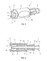
- FIG. 3 is a perspective view of an embodiment of a male connector conforming to the invention.
- FIG. 4 is a sectional view of the male connector of FIG. 3 ;
- FIG. 5A is a sectional view of an exemplary embodiment of a tubular body on which is fastened a valve conforming to the invention
- FIG. 5B is a perspective view of the distal portion of the exemplary embodiment of FIG. 5A ;
- FIG. 6 is a perspective view of an embodiment of the distal portion of a tubular body conforming to the invention.
- FIG. 7A is a perspective view of a section of an exemplary embodiment of a valve conforming to the invention.
- FIG. 7B is a sectional view of FIG. 7A ;
- FIG. 7C is a perspective view of the proximal portion of a valve conforming to FIG. 7A ;
- FIG. 8A is a perspective view of an assembly including the tubular body and the valve of FIG. 5B , an exemplary embodiment of a sliding ring and an exemplary embodiment of an elastic means conforming to the invention;
- FIG. 8B is a sectional view of the distal portion of the assembly of FIG. 7 ;
- FIG. 9 is a side view of a female connector and of a male connector in contact prior to assembly
- FIG. 10 is a sectional view of the female and male connectors of FIG. 9 ;
- FIG. 11 is a side view of a female connector and of a male connector connected and locked
- FIG. 12 is a sectional view of the female and male connectors of FIG. 11 ;
- FIG. 13 is a detail view of the connection of the female connector with the male connector of FIG. 12 .
- FIGS. 1 and 2 we will first of all describe a female connector 100 according to the invention.
- the female connector 100 comprises a proximal hub 120 , an elastically deformable, substantially tubular membrane 130 and a distal hub 140 attached to the proximal hub 120 .
- the proximal hub 120 has a generally tubular shape and comprises a proximal end which includes, here, a connectable entry 121 of the female “Luer lock” type. As a variant embodiment, this connectable entry 121 is of the male “Luer lock” type. It extends in the distal direction into a hollow body 122 .
- the hollow body 122 of the proximal hub 120 is terminated, in the distal direction, by a circular shaped flange 123 coaxially topped by a hollow connection tube 124 which extends, protruding from the proximal hub 120 in the distal direction.
- the hollow tube 124 terminates in a free distal end 125 and constitutes a connection member.
- This membrane 130 has a distal end 132 and comprises elastic means 131 .
- the elastic means 131 are a spring 131 , for example of the helical compression spring type, extending up to the distal end 132 . They are designed to be supported on the proximal hub 120 and to press the distal end 132 of the membrane 130 so that the latter goes into its rest (inactive) position, in which it plugs a distal end of the passage 141 .
- the distal end 132 of the membrane 130 is a septum having a distal surface which is convex overall, through which passes a slit coaxial with the connection tube 124 .
- the female connection 100 comprises a membrane 130 which is encapsulated in the tubular portion of the distal hub 140 , so that only the distal surface through which the slit passes is accessible to an operator. This also allows, in the rest position, radial clamping of the membrane 130 , and in particular of the distal end 132 of the latter, accomplished by a wall of the tubular portion of the distal hub 140 : better sealing and resistance to back-pressure are then obtained.
- the distal hub 140 comprises a locking means 150 .
- the locking means is female and of the bayonet type and includes a skirt 151 provided with grooves designed to cooperate with the male lugs of a complementary bayonet locking means.
- the distal end 152 of the distal hub 140 which is surrounded by the skirt 151 , is threaded so as to constitute a connectable entry of the female “Luer lock” type.
- the distal portion of the skirt 151 is shortened and offset so that the distal end face 151 is radially accessible.
- a female locking means is obtained which can be connected either to the lugs of a male bayonet locking means or to a complementary male “Luer lock” locking means.
- the male connector 1 includes a distal hub 10 comprising a tubular portion defining a passage, a proximal hub 20 and a connection member 30 .
- connection member 30 extends into the passage 11 of the distal hub 10 , coaxially with the tubular portion thereof. It has the form of a body which is tubular overall, forming an internal channel 31 of circular cylindrical shape overall, and has a valve 40 at a distal end 32 .
- the tubular body 30 is inserted into the distal hub 10 in such a way that the valve 40 is adjacent to the distal end 11 of the distal hub.
- the bulge 33 has the shape of a disk extending transversely to the axis of the tubular body, the outer diameter whereof is substantially equal to the inner diameter of the distal hub 10 .
- the disk also has snap-in means 33 a , for example a radial protrusion which can be annular, designed to cooperate with a groove 13 of complementary shape made in the inner face of the distal hub 10 , and is extended by a collar 33 b of greater diameter serving as a stop for the distal hub 10 .
- the proximal end 12 of the distal hub 10 rests against the collar 33 b serving as a stop and engages with the annular protrusion 33 a , so that the distal hub 10 is blocked in translation relative to the tubular body 30 .
- the tubular body 30 extends in its proximal portion beyond the radial bulge 33 into a zone 34 for gripping the proximal hub 20 .
- the gripping zone 34 includes a cylindrical body having, at an inner face, at least one connection member 34 a .
- the gripping zone 34 is a circular cylinder, the connection member 34 a then taking the form of an annular protrusion.
- the proximal hub 20 is fixed in translation on the tubular body 30 but free in rotation about it, so as to avoid accidental releases of the proximal hub 20 of the male connector 1 .
- the valve 40 of the tubular body 30 is an elastically deformable membrane, of cylindrical shape overall, and closed at a distal end 41 by a membrane.
- the outer diameter of the valve 40 is less than or equal to, preferably substantially equal to, the outer diameter of the membrane 130 .
- a slit 42 runs through the thickness of the membrane, leading to the tubular body 30 .
- the distal end of the tubular body 32 and the slit 42 can be separated by an internal space 43 extending the internal channel 31 .
- the slit 42 can be straight or beveled in the direction of the tubular body 30 , depending in particular on its manufacturing method.
- the valve 40 is made of an elastomeric material allowing the tubular body 30 to be sealingly closed despite the presence of the slit 42 .
- the valve 40 can be made of LSR (Liquid Silicone Rubber), while the tubular body 30 is made of a plastic material such as PBT (polybutylene terephthalate) plastic resin. It can then be overmolded onto the tubular body 30 .
- the distal end of the tubular body 30 can in particular have one or more radial openings 36 passing through it.
- the slit 42 is preferably made by cutting through the thickness of the membrane after fastening the valve 40 onto the tubular body 30 , for example by means of a scalpel, so as to be precisely indexed with respect to the tubular body 30 .
- the distal end 32 of the tubular body 30 on which is fastened the valve 40 , has an annular shoulder 32 a formed by shrinking the wall of the tubular body 30 so as to accommodate the valve 30 without creating a discontinuity at the outer surface of the connection member.
- the valve 40 is then overmolded (or fastened) into this shoulder 32 a over a thickness such that the outer wall 46 of the valve 40 and the tubular body 30 form a continuous surface which is smooth overall.
- the valve 40 includes in addition at least one blind groove 44 leading to the tubular body 30 and which is coaxial with the tubular body 30 .
- the groove 44 has a dual effect on the slit 42 .
- the groove 44 allows the slit 42 to open more easily, the edges of the slit 42 not being held back due to the empty space created by the groove 44 .
- the slit 42 when the slit 42 is closed (and thus has not object such as the connection tube 124 passing through it), in the event of migration of fluid coming from the tubular body 30 , the fluid enters the groove 44 and applies pressure on the edges of the slit which tends to push the edges of the slit 42 together. The slit 42 is therefore held closed and prevents the fluid from escaping, thus increasing the sealing of the connector 1 .
- the groove 44 can for example be of annular shape and extend around and at a distance from the slit, transverse to the axis of the tubular body 30 .
- the valve 40 includes two substantially rectilinear grooves 44 extending parallel to the slit 42 , on either side thereof. This embodiment has the advantage of applying a more effective pressure to the slit 42 , and hence of improving its resistance to counter-pressure.
- the grooves 44 are curved and on either side of the slit.
- the distal end 41 of the valve 40 is a concave surface.
- the surface of the distal end of the membrane 130 of the female connector 100 being of convex shape, this allows the distal end of the valve 40 to perfectly fit the surface of the membrane 130 , and thus to limit leakage of fluid when the connectors 1 and 100 are connected together.
- the concavity of the distal end 41 of the valve 40 matches the convexity of the distal end of the membrane 130 .
- the surface of the distal end of the membrane 130 of the female connector 100 is of concave shape; the distal end 41 of the valve 40 is then a convex surface with matching convexity.
- the male connector 1 also includes a sliding ring 50 mounted on the tubular body 30 , movable between an inactive, so-called rest position and a connection position.
- the ring 50 encapsulates the sidewalls 46 of the valve 40 , leaving free only its distal end 41 .
- the distal end 41 of the valve 40 is flush with the surface of the distal end 51 of the ring 50 , so as to minimize edges and facilitate the cleaning of the connector 1 .
- This position is particularly illustrated in FIGS. 3 , 4 , 8 A, 8 B and 10 .
- the ring 50 is located at a distance from the distal end 41 of the valve 40 and exposes all or a portion of the valve 40 .
- the inner diameter of the ring 50 is substantially equal to the outer diameter of the tubular body 30 and of the valve 40 .
- the valve 40 can also have a slight thickening 45 (on the order of 5% of the total thickness of the valve 40 ) extending radially at its distal end 41 , adjacent to the slit 42 .
- a slight thickening 45 on the order of 5% of the total thickness of the valve 40
- the ring 50 exerts a centripetal radial force on the valve 40 and the slit 42 . Consequently, at rest, the ring 50 further increases the resistance to counter-pressure of the valve 40 .
- the thickened portion 45 allows passage of fluid between the ring 50 and the valve 40 to be prevented.
- the thickened portion 45 is present only on either side of the slit 42 , so that the pressure is only exerted on either side thereof, this improving its resistance to counter-pressure.
- the thickened portion can have the shape of an ellipse, the minor diameter whereof (at the ends of the slit 42 ) is substantially equal to the inner diameter of the ring 50 , while the major diameter (at the edges of the slit 42 ) measures a few tenths of a millimeter more than the minor diameter.
- the outer diameter of the sliding ring 50 is preferably substantially equal to the inner diameter of the distal hub 10 , so as to limit passage of fluid between the ring 50 and the hub 10 .
- the outer surface of the ring 50 can also include an annular groove 52 designed to receive an O-ring gasket 53 , so as to further improve the sealing of the connector 1 and avoid the introduction of products such as disinfectants.
- the O-ring 53 can for example be made of an elastomeric material such as LSR silicone.
- the O-ring 53 is overmolded directly onto the ring 50 , with or without the annular groove 52 .
- the inner surface of the ring 50 which is in contact with the valve 40 , is preferably smooth, and for this purpose can have undergone surface treatment so as to facilitate the movement of the ring 50 along the tubular body 30 .
- the inner face of the ring 50 can be silicone-treated.
- Sliding of the ring 50 is further improved by the fact that the outer surface of the valve 40 and of the tubular body 30 is continuous and of constant diameter.
- the ring 50 can for example be made of a PBT type plastic material.
- the male connector 1 also includes a biasing means 60 , designed to return the sliding ring 50 to its rest position.
- the biasing means 60 is an elastic spring coaxial with the tubular body 30 , extending between the proximal face 54 of the sliding ring 50 and the distal face of the radial cavity 33 of the tubular body 30 . In this manner, when the sliding ring 50 is moved in toward its connection position, the spring 60 exerts on the ring 50 a biasing force tending to push the ring in the opposite direction, toward the distal end of the connector 1 .
- biasing means 60 is not limiting, however. It can also consist of a bellows operating in compression, etc.
- the sliding ring 50 is also in its rest position.
- the tubular body 30 can also be slit from its distal end toward its proximal end.
- the slit 35 a in the tubular body 30 extends over only a portion of the body 30 , for example in the distal portion which is in contact with the valve 40 , and confers on the distal portion of the body a certain radial elasticity.
- the slit 35 a of the tubular body 30 is substantially parallel to the slit 42 of the valve 40 .
- the slit 35 a is made in the tubular body 30 in such a way that the edges forming said slit 35 a are distant from one another.
- the distal portion of the tubular body 30 therefore consists of two lateral legs 35 b separated by the slit 35 a , as illustrated in FIG. 6 .
- the lateral legs 35 b of the tubular body 30 are radially constrained by the ring 50 toward the internal channel 31 of the tubular body 30 , so as to further improve the sealing of the slit 42 of the valve 40 , which improves the resistance to counter-pressure of the valve 40 .
- the space created by the slit 35 a allows the creation of a slit 42 of arbitrary width, without it being limited by the distal portion of the tubular body 30 .
- the distal hub 10 is fastened on the tubular body 30 and the sliding ring 50 , so that its distal end 12 rests against and engages with the radial thickening 33 and it encapsulates the sliding ring 50 and the valve 40 .
- the distal hub 10 is therefore immobile in translation with respect to the tubular body 30 .
- the distal hub can however be mobile in rotation about the tubular body 30 , for example when the protrusion 33 and the groove 13 are annular and extend coaxially with the tubular body 30 .
- the distal hub 10 also includes, at its distal end 11 , at least one curved centering wall 14 , which extends the outer surface of the distal end of the hub 10 .
- a centering wall 14 makes it possible to facilitate the alignment on the same axis of the male connector 1 and the corresponding female connector while they are being connected, which guarantees their correct operation and avoids deteriorating them.
- the distal hub 10 includes at least two facing centering walls 14 , separated radially by two notches 15 , so as to facilitate the cleaning of the flush distal surfaces 41 and 51 of the valve 40 and the sliding ring 50 .
- the internal face of the centering walls 14 can in addition include sloping protrusions 14 a extending radially inward in order to further improve guidance of the female connector 100 .
- the distal end 11 of the distal hub 10 also includes locking means 16 , preferably of the bayonet type.
- the locking means are two male lugs 16 of a bayonet system, each extending from an outer surface of a centering wall 14 .
- the distal end 11 of the distal hub 10 includes a distal skirt having female bayonet locking means.
- This type of locking means 16 has the advantage, compared with conventional threaded type locking means, of having surfaces which are smooth overall so that access to them is easy and they are therefore easy to clean. Moreover, they provide simple and secure locking of the male connector 1 with a corresponding female connector 100 .
- the distal hub 10 also includes means 15 for holding the male connector 1 .
- they are two in number and take the form of two cavities which extend radially on either side of the distal hub 10 .
- These grasping means 15 make it possible to firmly hold the male connector 1 when connecting it with the female connector 100 .
- the proximal hub 20 comprises at its proximal end 22 a conventional connectable entry 23 of the female “Luer lock” type, capable of being assembled to a syringe (or any other suitable medical equipment) having a connection end of the male “Luer” “slip” (smooth) or “lock” (locking) type, in a manner not shown in the figures.
- This connectable entry 23 is preferably sealed against pressures of up to 3 bars.
- the outer diameter of the proximal portion 34 of the tubular body 30 is slightly larger than the inner diameter of the proximal hub 20 at its connectable entry 23 .
- the proximal hub 20 includes a circular cylindrical gripping member 24 coaxial with the tubular body 30 , designed to cooperate with the corresponding gripping member 34 a corresponding to the gripping zone of the tubular body 30 .
- the proximal hub 20 is fixed in translation on the tubular body 30 , while remaining mobile in rotation about the axis thereof. Any unintended rotary motion of the male connector 1 (for example during disconnection of the male connector 1 and a female connector 100 by rotation of said connectors 1 and 100 so as to disconnect their bayonet locking means 16 ) is therefore compensated by the free rotation of the distal hub 20 with respect to the tubular body 30 , thus avoiding accidental disconnections of the male connector 1 and of the syringe.
- the female connector corresponds to the connector 100 described previously with reference to the appended FIGS. 1 and 2 and detailed in document EP 2011/05231. This is not limiting, however.
- the distal ends of the two connectors 1 and 100 are cleaned. This cleaning is all the easier because the valve 40 and the membrane 130 of the male 1 and female 100 connectors, respectively, are flush with the distal ends of the distal hubs so that the distal surface of each connector 1 , 100 is smooth. If necessary, replacement of conventional threads by bayonet locking means 16 , 150 also facilitates this cleaning, thanks to the offset of the skirt 151 of the female connector 100 , which allow easy access to the threads of the distal end 152 of the connector 100 , as well as the absence of conventional threads on the locking means of the male connector.
- the operator brings the respective distal ends of the male and female 100 connectors into contact. To this end, he applies the concave surface of the valve 40 to the convex surface of the membrane 130 and the distal end of the distal hub 140 onto the distal end 51 of the sliding ring 50 , as illustrated in FIGS. 9 and 10 , then connects the assembly.
- distal hubs 140 and 10 of the two connectors, female 100 and male 1 are structurally similar (aside of course from their respective locking means): the membrane 130 and the valve 40 are indeed flush with the distal end of their distal hub 140 , 10 so that coupling/uncoupling of the male connector 1 and the female connector 100 is accomplished with only one axial motion. It is in fact no longer necessary to attach the distal hubs 140 , 10 of the female 100 and male 1 connectors before beginning to push the connectors together, the two operations being performed simultaneously thanks to the structure of the distal hubs 140 , 240 .
- the operator places the respective locking means of the male and female connector facing one another, then locks them.
- the operator places for example the lugs 16 of the male connector 1 facing the corresponding grooves 150 of the female connector 100 , the slides the connectors 100 , 1 relative to one another by pushing the male connector 1 , supported by the centering means 14 of its distal hub 10 , toward the female connector 100 .
- valve 40 of the male connector 1 presses on the distal end of the membrane 130 of the female connector 100 , while the distal hub 140 of the female connector 100 presses on the sliding ring 50 of the male connector. Consequently, the valve 40 and a portion of the tubular body 30 of the male connector 1 penetrate into the distal hub 140 of the female connector 100 , while the distal end of the distal hub 140 of the male connector 100 penetrates into the distal end 11 of the distal hub 10 of the male connector 1 .
- valve 40 forces the elastic means 131 to compress, so that the membrane 30 moves back toward its connection position, which forces the distal end 125 of the hollow tube 124 to cross, through the slit 133 , the septum situated at the distal end of the membrane 130 .
- the distal end of the distal hub 140 of the female connector 100 which is resting against the sliding ring 50 , forces the return means 60 to compress, and thus moves the sliding ring 50 toward its connection position.
- the valve 40 and the tubular body 30 do not move with respect to the distal hub 10 and to the proximal hub 20 of the male connector 1 .
- valve 40 does not open as long as the distal end 125 of the hollow tube 124 of the female connector 100 does not pass through the membrane, particularly due to the axial stiffness conferred by the distal portion of the tubular body 30 on which is fixed the valve 40 .
- the material and the thickness of the valve 40 are selected so that it is sufficiently strong when it pushes the membrane 130 so as not to open and sag toward the tubular body 30 .
- the object in fact, is to that the valve 40 be capable of transmitting to the membrane 130 of the female connector 100 the thrust force applied by the operator on the gripping means 14 to force the membrane 130 of the female connector 100 to move back toward its connection position wherein the distal end 125 of the connection tube 124 passes through the membrane 130 .
- valve 40 This resistance to sagging of the valve 40 is also reinforced axially by the fact that the valve 40 is fastened on the distal portion of the tubular body 30 . What is more, the presence of the lateral legs 35 b further reinforces, if necessary, the axial stiffness of the valve 40 .
- this distal end 125 of the tube 124 is in supporting contact with the valve 40 of the male connector 1 .
- the distal end 125 of the tube 124 presses on the distal end 41 of the valve 40 , finally penetrating into the slit 42 of the valve 40 .
- the elastic means are already strongly compressed and exert a return force greater than that of the edges of the slit 42 , so that these yield and spread apart to allow passage of the connection tube 124 .
- connection tube 124 of the female connector 100 does not necessarily penetrate into the distal end of the tubular body 30 . In fact, it is sufficient for it to be adjacent to it, as illustrated in FIGS. 12 and 13 .
- the tubular body 30 opens along its slit 35 a . This opening is facilitated by the presence of the lateral legs 35 b , which confer flexibility (in the direction perpendicular to the plane of the slit 35 a ) to the distal end of the tubular body 30 and allow its elastic deformation under the influence of the connection tube 124 on the valve 40 .
- valve 40 sags partially and the lateral legs 35 b of the tubular body 30 deform elastically so as to move away from one another, thus reducing the axial resistance that they exert on the valve 40 so as to facilitate passage of the distal end 125 .
- the sliding ring 50 is near to its connection position, so that it does not prevent this opening.
- the sliding ring 50 tends to hold the slit 35 a of the tubular body 30 closed.
- the spreading of the edges of the slit 42 can also be facilitated by the groove 44 , if any.
- the operator When disconnecting, the operator unlocks the locking means of the connectors 1 and 100 , for example by turning the connectors relative to one another in the case of bayonet locking means, then separates the connectors 1 , 100 with the help of the thrust of the elastic means 131 and of the return means 60 .
- the free end 125 of the connection tube 124 emerges from the valve 40 , which allows the slit 42 to close again.
- This closing of the slit 42 is further improved thanks to the elastic return of the lateral legs 35 b , which tends to bring the lateral legs 35 b into the initial rest position, wherein the lateral legs 35 b exert a radial force toward the inner channel 31 on the slit 42 .
- the membrane 130 then gradually covers again the free end 125 of the tube 124 until it sealingly plugs it: the membrane 130 is then in its rest position.
- valve 40 and the tubular body 30 emerge from the distal hub 140 of the female connector 100 , which for its part gradually emerges from the distal hub 10 of the male connector 1 , thus allowing the sliding ring 50 to return to its rest position.
- sealing is ensured throughout the operation. In fact, sealing is provided by contact, at all times, between the membrane 130 and the valve 40 .
- connection tube 124 which moreover is very narrow
- the male connector also includes a connection tube which passes through both membranes.
- the connection tube of prior art male connectors is moreover relatively large compared with the connection tube 124 , so that the slit in the membrane 130 and the slit 42 in the valve 40 must open wider to allow it to pass.
- the slit 133 of the membrane 130 and of the valve 40 therefore open much less than in the prior art, so that it becomes much more difficult for the fluid to enter it, thus reducing the formation of drops at the time of disconnection.
Applications Claiming Priority (3)
| Application Number | Priority Date | Filing Date | Title |
|---|---|---|---|
| FR1156955A FR2978353B1 (fr) | 2011-07-29 | 2011-07-29 | Connecteurs a flux direct anti-goutte et a verrouillage securise |
| FR1156955 | 2011-07-29 | ||
| PCT/EP2012/064669 WO2013017518A1 (fr) | 2011-07-29 | 2012-07-26 | Connecteurs à flux direct anti-goutte et à verrouillage sécurisé |
Publications (2)
| Publication Number | Publication Date |
|---|---|
| US20140209197A1 US20140209197A1 (en) | 2014-07-31 |
| US9234616B2 true US9234616B2 (en) | 2016-01-12 |
Family
ID=46598507
Family Applications (1)
| Application Number | Title | Priority Date | Filing Date |
|---|---|---|---|
| US14/235,966 Active US9234616B2 (en) | 2011-07-29 | 2012-07-26 | Non-drip, direct-flow connectors with secure locking |
Country Status (10)
| Country | Link |
|---|---|
| US (1) | US9234616B2 (ja) |
| EP (1) | EP2736582B1 (ja) |
| JP (1) | JP6046715B2 (ja) |
| KR (1) | KR101934452B1 (ja) |
| BR (1) | BR112014002192B1 (ja) |
| CA (1) | CA2843149C (ja) |
| ES (1) | ES2544547T3 (ja) |
| FR (1) | FR2978353B1 (ja) |
| PT (1) | PT2736582E (ja) |
| WO (1) | WO2013017518A1 (ja) |
Cited By (13)
| Publication number | Priority date | Publication date | Assignee | Title |
|---|---|---|---|---|
| USD786427S1 (en) | 2014-12-03 | 2017-05-09 | Icu Medical, Inc. | Fluid manifold |
| USD793551S1 (en) | 2014-12-03 | 2017-08-01 | Icu Medical, Inc. | Fluid manifold |
| US9775981B2 (en) | 2013-03-15 | 2017-10-03 | Icu Medical, Inc. | Medical connector |
| US9933094B2 (en) | 2011-09-09 | 2018-04-03 | Icu Medical, Inc. | Medical connectors with fluid-resistant mating interfaces |
| US10046154B2 (en) | 2008-12-19 | 2018-08-14 | Icu Medical, Inc. | Medical connector with closeable luer connector |
| US10086170B2 (en) | 2014-02-04 | 2018-10-02 | Icu Medical, Inc. | Self-priming systems and methods |
| US10159818B2 (en) | 2010-05-19 | 2018-12-25 | Tangent Medical Technologies, Inc. | Safety needle system operable with a medical device |
| US10179231B2 (en) | 2012-11-12 | 2019-01-15 | Icu Medical, Inc. | Medical connector |
| US10369349B2 (en) | 2013-12-11 | 2019-08-06 | Icu Medical, Inc. | Medical fluid manifold |
| US10569057B2 (en) | 2010-05-19 | 2020-02-25 | Tangent Medical Technologies, Inc. | Integrated vascular delivery system |
| US10668252B2 (en) | 2009-08-14 | 2020-06-02 | The Regents Of The University Of Michigan | Integrated vascular delivery system |
| US10731768B2 (en) | 2016-10-12 | 2020-08-04 | Ecolab Usa Inc. | Systems and methods for manifold valves |
| US10953215B2 (en) | 2015-04-08 | 2021-03-23 | Dale Medical Products, Inc. | Non-luer compatible administration port |
Families Citing this family (16)
| Publication number | Priority date | Publication date | Assignee | Title |
|---|---|---|---|---|
| WO2006052655A2 (en) | 2004-11-05 | 2006-05-18 | Icu Medical, Inc. | Soft-grip medical connector |
| US8454579B2 (en) | 2009-03-25 | 2013-06-04 | Icu Medical, Inc. | Medical connector with automatic valves and volume regulator |
| USD644731S1 (en) | 2010-03-23 | 2011-09-06 | Icu Medical, Inc. | Medical connector |
| US8758306B2 (en) | 2010-05-17 | 2014-06-24 | Icu Medical, Inc. | Medical connectors and methods of use |
| ES2780857T3 (es) * | 2013-11-06 | 2020-08-27 | Becton Dickinson & Co Ltd | Aparato de conexión para un dispositivo médico |
| EP3199200A4 (en) * | 2014-09-24 | 2018-05-09 | Terumo Kabushiki Kaisha | Medical connector |
| US20160166821A1 (en) * | 2014-12-15 | 2016-06-16 | Intermountain Invention Management, Llc | Devices for restraining movement of elongated medical implements and related systems and methods |
| ES2849251T3 (es) * | 2015-06-24 | 2021-08-17 | Linear Health Sciences Llc | Sistema de tubo |
| EP3331598A4 (en) * | 2015-08-07 | 2019-03-13 | Merit Medical Systems, Inc. | MEDICAL SEPARABLE CONNECTORS |
| SE1651467A1 (sv) * | 2016-11-09 | 2018-05-10 | Tada Medical Ab | Coupling device |
| USD865954S1 (en) | 2018-03-30 | 2019-11-05 | Merit Medical Systems, Inc. | Breakaway connector |
| USD905235S1 (en) | 2018-03-30 | 2020-12-15 | Merit Medical Systems, Inc. | Kit of breakaway connectors |
| CN110701338A (zh) * | 2019-10-31 | 2020-01-17 | 清谱(上海)分析仪器有限公司 | 一种真空保持装置及真空器件 |
| EP3831426A1 (de) * | 2019-12-05 | 2021-06-09 | Heraeus Medical GmbH | Vorrichtung zur lokalen applikation von pharmazeutischen fluiden |
| SE545166C2 (en) * | 2020-06-24 | 2023-04-25 | Cyto365 Ab | A closed-system type female connector, a method for manufacture, and a stopcock having such female connectors |
| WO2023146639A1 (en) * | 2022-01-25 | 2023-08-03 | Becton, Dickinson And Company | Catheter system having a locking cap |
Citations (11)
| Publication number | Priority date | Publication date | Assignee | Title |
|---|---|---|---|---|
| EP0544581A1 (fr) | 1991-11-25 | 1993-06-02 | Société VYGON | Connecteur composite unitaire pour circuit de liquide notamment à usage médical |
| US5492147A (en) * | 1995-01-17 | 1996-02-20 | Aeroquip Corporation | Dry break coupling |
| WO2000020070A1 (en) | 1998-10-05 | 2000-04-13 | Rymed Technologies, Inc. | Swabbable needleless low reflux injection port system |
| US6168137B1 (en) * | 1996-12-30 | 2001-01-02 | Joseph R. Paradis | Swabbable check valve |
| US20030209681A1 (en) | 2002-05-08 | 2003-11-13 | Leinsing Karl R. | Needle-free medical connector with expandable valve mechanism and method of fluid flow control |
| WO2006062912A1 (en) | 2004-12-10 | 2006-06-15 | Cardinal Health 303, Inc. | Self-sealing male luer connector with multiple seals |
| WO2008052140A2 (en) | 2006-10-25 | 2008-05-02 | Icu Medical, Inc. | Medical connector |
| US20080183155A1 (en) | 2007-01-19 | 2008-07-31 | Tyco Healthcare Group Lp | Male Luer Connector |
| WO2011101389A1 (fr) | 2010-02-17 | 2011-08-25 | Vygon | Ensemble de connecteurs facilement nettoyable pour un circuit liquide |
| US8048039B2 (en) * | 2006-09-29 | 2011-11-01 | Tyco Healthcare Group Lp | Surgical fluid transfer apparatus |
| US8671966B2 (en) * | 2006-11-17 | 2014-03-18 | B. Braun Medical Inc. | Needleless access port valves |
Family Cites Families (6)
| Publication number | Priority date | Publication date | Assignee | Title |
|---|---|---|---|---|
| NL8300386A (nl) * | 1983-02-02 | 1984-09-03 | Steritech Bv | Inrichting voor het steriel met elkaar in verbinding stellen van twee kamers. |
| US5957898A (en) * | 1997-05-20 | 1999-09-28 | Baxter International Inc. | Needleless connector |
| DE19828651C2 (de) * | 1998-06-26 | 2000-07-13 | Fresenius Medical Care De Gmbh | Konnektorelement mit Verschlußteil für die Medizintechnik |
| US6964406B2 (en) * | 2001-08-10 | 2005-11-15 | Alaris Medical Systems, Inc. | Valved male luer |
| US7651481B2 (en) * | 2004-12-30 | 2010-01-26 | CareFusion 303 Inc. | Self-sealing male connector device with collapsible body |
| WO2006124756A2 (en) * | 2005-05-13 | 2006-11-23 | Bob Rogers | Medical substance transfer system |
-
2011
- 2011-07-29 FR FR1156955A patent/FR2978353B1/fr not_active Expired - Fee Related
-
2012
- 2012-07-26 PT PT127409522T patent/PT2736582E/pt unknown
- 2012-07-26 BR BR112014002192-9A patent/BR112014002192B1/pt active IP Right Grant
- 2012-07-26 KR KR1020147005391A patent/KR101934452B1/ko active IP Right Grant
- 2012-07-26 ES ES12740952.2T patent/ES2544547T3/es active Active
- 2012-07-26 WO PCT/EP2012/064669 patent/WO2013017518A1/fr active Application Filing
- 2012-07-26 JP JP2014522097A patent/JP6046715B2/ja active Active
- 2012-07-26 CA CA2843149A patent/CA2843149C/fr active Active
- 2012-07-26 EP EP20120740952 patent/EP2736582B1/fr active Active
- 2012-07-26 US US14/235,966 patent/US9234616B2/en active Active
Patent Citations (12)
| Publication number | Priority date | Publication date | Assignee | Title |
|---|---|---|---|---|
| EP0544581A1 (fr) | 1991-11-25 | 1993-06-02 | Société VYGON | Connecteur composite unitaire pour circuit de liquide notamment à usage médical |
| US5492147A (en) * | 1995-01-17 | 1996-02-20 | Aeroquip Corporation | Dry break coupling |
| US6168137B1 (en) * | 1996-12-30 | 2001-01-02 | Joseph R. Paradis | Swabbable check valve |
| WO2000020070A1 (en) | 1998-10-05 | 2000-04-13 | Rymed Technologies, Inc. | Swabbable needleless low reflux injection port system |
| US6113068A (en) * | 1998-10-05 | 2000-09-05 | Rymed Technologies | Swabbable needleless injection port system having low reflux |
| US20030209681A1 (en) | 2002-05-08 | 2003-11-13 | Leinsing Karl R. | Needle-free medical connector with expandable valve mechanism and method of fluid flow control |
| WO2006062912A1 (en) | 2004-12-10 | 2006-06-15 | Cardinal Health 303, Inc. | Self-sealing male luer connector with multiple seals |
| US8048039B2 (en) * | 2006-09-29 | 2011-11-01 | Tyco Healthcare Group Lp | Surgical fluid transfer apparatus |
| WO2008052140A2 (en) | 2006-10-25 | 2008-05-02 | Icu Medical, Inc. | Medical connector |
| US8671966B2 (en) * | 2006-11-17 | 2014-03-18 | B. Braun Medical Inc. | Needleless access port valves |
| US20080183155A1 (en) | 2007-01-19 | 2008-07-31 | Tyco Healthcare Group Lp | Male Luer Connector |
| WO2011101389A1 (fr) | 2010-02-17 | 2011-08-25 | Vygon | Ensemble de connecteurs facilement nettoyable pour un circuit liquide |
Non-Patent Citations (2)
| Title |
|---|
| French Preliminary Search Report for Application No. FR 1156955 dated Jun. 22, 2012. |
| International Search Report for Application No. PCT/EP2012/064669 dated Aug. 30, 2012. |
Cited By (32)
| Publication number | Priority date | Publication date | Assignee | Title |
|---|---|---|---|---|
| US10716928B2 (en) | 2008-12-19 | 2020-07-21 | Icu Medical, Inc. | Medical connector with closeable luer connector |
| US11478624B2 (en) | 2008-12-19 | 2022-10-25 | Icu Medical, Inc. | Medical connector with closeable luer connector |
| US10046154B2 (en) | 2008-12-19 | 2018-08-14 | Icu Medical, Inc. | Medical connector with closeable luer connector |
| US10668252B2 (en) | 2009-08-14 | 2020-06-02 | The Regents Of The University Of Michigan | Integrated vascular delivery system |
| US11577053B2 (en) | 2009-08-14 | 2023-02-14 | The Regents Of The University Of Michigan | Integrated vascular delivery system |
| US11577052B2 (en) | 2010-05-19 | 2023-02-14 | Tangent Medical Technologies, Inc. | Integrated vascular delivery system |
| US10905858B2 (en) | 2010-05-19 | 2021-02-02 | Tangent Medical Technologies, Inc. | Safety needle system operable with a medical device |
| US10569057B2 (en) | 2010-05-19 | 2020-02-25 | Tangent Medical Technologies, Inc. | Integrated vascular delivery system |
| US10159818B2 (en) | 2010-05-19 | 2018-12-25 | Tangent Medical Technologies, Inc. | Safety needle system operable with a medical device |
| US11808389B2 (en) | 2011-09-09 | 2023-11-07 | Icu Medical, Inc. | Medical connectors with luer-incompatible connection portions |
| US10156306B2 (en) | 2011-09-09 | 2018-12-18 | Icu Medical, Inc. | Axially engaging medical connector system with fluid-resistant mating interfaces |
| US9933094B2 (en) | 2011-09-09 | 2018-04-03 | Icu Medical, Inc. | Medical connectors with fluid-resistant mating interfaces |
| US10697570B2 (en) | 2011-09-09 | 2020-06-30 | Icu Medical, Inc. | Axially engaging medical connector system with diminished fluid remnants |
| US11168818B2 (en) | 2011-09-09 | 2021-11-09 | Icu Medical, Inc. | Axially engaging medical connector system that inhibits fluid penetration between mating surfaces |
| US10179231B2 (en) | 2012-11-12 | 2019-01-15 | Icu Medical, Inc. | Medical connector |
| US11872365B2 (en) | 2012-11-12 | 2024-01-16 | Icu Medical, Inc. | Medical connector |
| US10792486B2 (en) | 2012-11-12 | 2020-10-06 | Icu Medical, Inc. | Medical connector |
| US11786716B2 (en) | 2013-03-15 | 2023-10-17 | Icu Medical, Inc. | Medical connector |
| US10668268B2 (en) | 2013-03-15 | 2020-06-02 | Icu Medical, Inc. | Medical connector |
| US9775981B2 (en) | 2013-03-15 | 2017-10-03 | Icu Medical, Inc. | Medical connector |
| US11364372B2 (en) | 2013-12-11 | 2022-06-21 | Icu Medical, Inc. | Check valve |
| US10369349B2 (en) | 2013-12-11 | 2019-08-06 | Icu Medical, Inc. | Medical fluid manifold |
| US10814107B2 (en) | 2014-02-04 | 2020-10-27 | Icu Medical, Inc. | Self-priming systems and methods |
| US11724071B2 (en) | 2014-02-04 | 2023-08-15 | Icu Medical, Inc. | Self-priming systems and methods |
| US10086170B2 (en) | 2014-02-04 | 2018-10-02 | Icu Medical, Inc. | Self-priming systems and methods |
| USD786427S1 (en) | 2014-12-03 | 2017-05-09 | Icu Medical, Inc. | Fluid manifold |
| USD890335S1 (en) | 2014-12-03 | 2020-07-14 | Icu Medical, Inc. | Fluid manifold |
| USD849939S1 (en) | 2014-12-03 | 2019-05-28 | Icu Medical, Inc. | Fluid manifold |
| USD826400S1 (en) | 2014-12-03 | 2018-08-21 | Icu Medical, Inc. | Fluid manifold |
| USD793551S1 (en) | 2014-12-03 | 2017-08-01 | Icu Medical, Inc. | Fluid manifold |
| US10953215B2 (en) | 2015-04-08 | 2021-03-23 | Dale Medical Products, Inc. | Non-luer compatible administration port |
| US10731768B2 (en) | 2016-10-12 | 2020-08-04 | Ecolab Usa Inc. | Systems and methods for manifold valves |
Also Published As
| Publication number | Publication date |
|---|---|
| US20140209197A1 (en) | 2014-07-31 |
| EP2736582A1 (fr) | 2014-06-04 |
| WO2013017518A1 (fr) | 2013-02-07 |
| PT2736582E (pt) | 2015-09-17 |
| FR2978353B1 (fr) | 2013-08-02 |
| CA2843149A1 (fr) | 2013-02-07 |
| EP2736582B1 (fr) | 2015-05-06 |
| JP6046715B2 (ja) | 2016-12-21 |
| FR2978353A1 (fr) | 2013-02-01 |
| WO2013017518A8 (fr) | 2014-02-27 |
| KR101934452B1 (ko) | 2019-01-03 |
| ES2544547T3 (es) | 2015-09-01 |
| JP2014528741A (ja) | 2014-10-30 |
| CA2843149C (fr) | 2019-07-16 |
| BR112014002192A2 (pt) | 2017-02-21 |
| KR20140057572A (ko) | 2014-05-13 |
| BR112014002192B1 (pt) | 2020-12-01 |
Similar Documents
| Publication | Publication Date | Title |
|---|---|---|
| US9234616B2 (en) | Non-drip, direct-flow connectors with secure locking | |
| US9492649B2 (en) | Set of easily cleanable connectors for a liquid circuit | |
| US8910919B2 (en) | Selectively sealable male needleless connectors and associated methods | |
| AU2016201947B2 (en) | New needleless access connector and method of use | |
| RU2524307C2 (ru) | Закрытое охватываемое устройство люэровского типа для сведения к минимуму утечек жидкости во время соединения и отсоединения | |
| US8133209B2 (en) | Valve connector for medical lines | |
| JP6553357B2 (ja) | 耐流体性嵌合インターフェースを備えた医療用コネクタ | |
| US9851037B2 (en) | Fluid connector and method for making sealed fluid connections | |
| JP2006515190A (ja) | バイアス式弁栓を備える自動封止雄ルーアーコネクタ | |
| JP2008513119A (ja) | 成形エラストマー先端を有するセルフシール雄ルアーコネクタ | |
| KR102443476B1 (ko) | 밸브형 수 루어 커넥터 | |
| JP2008264030A (ja) | 医療ライン用バルブコネクタ | |
| KR20210099039A (ko) | 스톱 콕 밸브용 이중 단부형 소독 캡 | |
| US11617874B2 (en) | Luer connector | |
| EP3202390A1 (en) | Pharmaceutical adaptor system and pharmaceutical kit system | |
| JP2001079099A (ja) | 針無しコネクター |
Legal Events
| Date | Code | Title | Description |
|---|---|---|---|
| AS | Assignment |
Owner name: VYGON, FRANCE Free format text: ASSIGNMENT OF ASSIGNORS INTEREST;ASSIGNORS:CARREZ, JEAN-LUC;BARRE, LAURENT;PECH, MARIE-HELENE;SIGNING DATES FROM 20130308 TO 20130322;REEL/FRAME:032542/0295 |
|
| STCF | Information on status: patent grant |
Free format text: PATENTED CASE |
|
| MAFP | Maintenance fee payment |
Free format text: PAYMENT OF MAINTENANCE FEE, 4TH YEAR, LARGE ENTITY (ORIGINAL EVENT CODE: M1551); ENTITY STATUS OF PATENT OWNER: LARGE ENTITY Year of fee payment: 4 |
|
| MAFP | Maintenance fee payment |
Free format text: PAYMENT OF MAINTENANCE FEE, 8TH YEAR, LARGE ENTITY (ORIGINAL EVENT CODE: M1552); ENTITY STATUS OF PATENT OWNER: LARGE ENTITY Year of fee payment: 8 |