US9227490B2 - Guide rail for a sliding roof system and method of producing such a guide rail - Google Patents
Guide rail for a sliding roof system and method of producing such a guide rail Download PDFInfo
- Publication number
- US9227490B2 US9227490B2 US13/814,853 US201113814853A US9227490B2 US 9227490 B2 US9227490 B2 US 9227490B2 US 201113814853 A US201113814853 A US 201113814853A US 9227490 B2 US9227490 B2 US 9227490B2
- Authority
- US
- United States
- Prior art keywords
- guide
- guide rail
- legs
- section
- web
- Prior art date
- Legal status (The legal status is an assumption and is not a legal conclusion. Google has not performed a legal analysis and makes no representation as to the accuracy of the status listed.)
- Active, expires
Links
Images


Classifications
-
- B—PERFORMING OPERATIONS; TRANSPORTING
- B60—VEHICLES IN GENERAL
- B60J—WINDOWS, WINDSCREENS, NON-FIXED ROOFS, DOORS, OR SIMILAR DEVICES FOR VEHICLES; REMOVABLE EXTERNAL PROTECTIVE COVERINGS SPECIALLY ADAPTED FOR VEHICLES
- B60J7/00—Non-fixed roofs; Roofs with movable panels, e.g. rotary sunroofs
- B60J7/02—Non-fixed roofs; Roofs with movable panels, e.g. rotary sunroofs of sliding type, e.g. comprising guide shoes
- B60J7/024—Non-fixed roofs; Roofs with movable panels, e.g. rotary sunroofs of sliding type, e.g. comprising guide shoes characterised by the height regulating mechanism of the sliding panel
-
- B—PERFORMING OPERATIONS; TRANSPORTING
- B60—VEHICLES IN GENERAL
- B60J—WINDOWS, WINDSCREENS, NON-FIXED ROOFS, DOORS, OR SIMILAR DEVICES FOR VEHICLES; REMOVABLE EXTERNAL PROTECTIVE COVERINGS SPECIALLY ADAPTED FOR VEHICLES
- B60J7/00—Non-fixed roofs; Roofs with movable panels, e.g. rotary sunroofs
- B60J7/02—Non-fixed roofs; Roofs with movable panels, e.g. rotary sunroofs of sliding type, e.g. comprising guide shoes
- B60J7/04—Non-fixed roofs; Roofs with movable panels, e.g. rotary sunroofs of sliding type, e.g. comprising guide shoes with rigid plate-like element or elements, e.g. open roofs with harmonica-type folding rigid panels
- B60J7/043—Sunroofs e.g. sliding above the roof
- B60J7/0435—Sunroofs e.g. sliding above the roof pivoting upwardly to vent mode and moving at the outside of the roof to fully open mode
-
- Y—GENERAL TAGGING OF NEW TECHNOLOGICAL DEVELOPMENTS; GENERAL TAGGING OF CROSS-SECTIONAL TECHNOLOGIES SPANNING OVER SEVERAL SECTIONS OF THE IPC; TECHNICAL SUBJECTS COVERED BY FORMER USPC CROSS-REFERENCE ART COLLECTIONS [XRACs] AND DIGESTS
- Y10—TECHNICAL SUBJECTS COVERED BY FORMER USPC
- Y10T—TECHNICAL SUBJECTS COVERED BY FORMER US CLASSIFICATION
- Y10T29/00—Metal working
- Y10T29/49—Method of mechanical manufacture
- Y10T29/49815—Disassembling
Definitions
- the present invention relates to a guide rail for a vehicle sliding roof system, including a guide slot which can receive a sliding element for shifting motion that is coupled to a cover of the sliding roof system, the guide slot including a shifting section that extends substantially in a straight line, and the guide rail being made of metal, in particular of an aluminum alloy.
- the invention further relates to a method of producing such a guide rail.
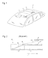
- a guide rail for a vehicle sliding roof system is disclosed in DE 20 2005 007 475. It is part of a sliding roof system 4 which is schematically shown in FIG. 1 with respect to a vehicle 1 having a vehicle roof 2 .
- the sliding roof system 4 includes two cover parts 6 , 8 , of which at least the first cover part 6 is adjustable.
- the sliding roof system 4 may, of course, also be a so-called sliding/tilting roof.
- a guide rail 10 ′ which is shown in FIG. 2 is part of the sliding roof system 4 .
- the guide rail includes a guide slot which consists of two sections, namely, a lifting section 16 ′ which, as viewed in the longitudinal direction L of the guide rail 10 ′, extends obliquely upward and to the rear, and a shifting section 17 ′ which extends substantially in a straight line and parallel to the longitudinal direction L.
- the lifting section 16 ′ serves to initially raise a cover part 6 ′ that is guided in the guide slot via a carriage 20 ′ having a sliding element 18 ′ mounted thereto, upon an adjustment of the cover part 6 ′ in the longitudinal direction of the vehicle.
- the sliding element is guided in the shifting section 17 ′ to the rear substantially parallel to the longitudinal direction L of the guide rail (and thus of the vehicle).
- the guide rail may be configured to be generally slightly curved, so that it can follow the curvature of the roof 2 or a curved longitudinal edge of the roof opening. But, for simplification, the guide rail is considered to be “straight” here.
- the term “oblique” here is understood to mean an orientation of the lifting section 16 ′ that significantly differs from the direction of extent of the shifting section 17 ′, in particular by more than 20 degrees.
- the guide rail 10 ′ is designed in two parts, namely, a rail element 14 ′ and an attachment part 12 ′.
- the rail element 14 ′ only contains the shifting section 17 ′, running in a straight line, of the guide slot.
- The allows the rail element 14 ′ to be produced from a profiled part which is extruded, for example.
- the lifting section 16 ′ which extends obliquely to the longitudinal direction of the guide rail 10 ′, is formed in the attachment part 12 ′, which consists of a plastic material, for example, and is fitted to the front end (in relation to the vehicle) of the rail element 14 ′, so that the guide rail 10 ′ is formed.
- a disadvantage of this configuration is that when the cover part 6 ′ is shifted to the rear, the sliding element 18 ′ needs to travel over the abutting edges of the joint between the rail element 14 ′ and the attachment part 12 ′. This leads to wear, noises and, possibly, a spurious response of an anti-pinch protection.
- the object of the invention resides in further developing a guide rail of the type initially mentioned to the effect that the wear and noises that are generated when the sliding element moves from the lifting section to the shifting section are reduced.
- a guide rail of the type initially mentioned that it includes a lifting section which integrally adjoins the shifting section and extends obliquely to the direction of extent of the shifting section.
- the invention is based on the fundamental concept of totally eliminating the joint between the lifting section and the shifting section so as to obtain a continuous guide for the sliding element.
- the guide is formed by at least one guide web around which the sliding element engages on two sides. This allows the lifting section to be bent in relation to the shifting section with comparatively little effort, so that the guide rail can still be formed starting from a straight profiled part.
- the guide is formed by two legs that are located opposite each other and each have an end provided with the guide web. Owing to this design, the sliding element is guided particularly reliably in a direction transverse to the guide rail.
- the legs are connected with each other by a base part in the region of the shifting section. In this way, a very stable guide rail is obtained.
- the legs are connected with each other by at least one connecting web which is arranged on the side facing away from the guide web.
- the connecting web increases the stability of the guide rail in the region of the lifting section, so that the sliding element is reliably guided in that region, too.
- the connecting web may be provided with an opening which can receive a fastening element. This allows the guide rail to be bolted to a carrier frame, for example.
- a method of producing a guide rail for a vehicle sliding roof system including the steps of: at first, providing a straight profiled rail made of an aluminum alloy which includes a guide for a sliding element, the guide being formed by two webs that are arranged side by side and are connected with each other by a base part and each include a guide web on their side facing away from the base part; subsequently, removing sections of the base part; then, bending the webs in that section in which the base part has been removed, so that a lifting section is formed which extends obliquely to the remaining shifting section of the guide rail.
- This method is based on the fundamental concept of using an inherently stiff profiled rail which may be extruded, for example.
- the obliquely bent lifting section is produced in that the base part is removed in sections. This purposefully weakens the profiled part in such a manner that the lifting section may be bent off while at the same time a sufficient stability is still provided.
- this removal of sections of the base part allows the webs to be held in position during deformation.
- FIG. 1 shows a schematic view of a vehicle roof with a sliding roof system
- FIG. 2 shows a schematic sectional view of a guide rail according to the prior art
- FIG. 3 shows a guide rail according to the invention, in section
- FIG. 4 shows a top view of the guide rail of FIG. 3 :
- FIG. 5 shows a section taken along the plane V-V of FIG. 4 ;
- FIG. 6 shows a section taken along the plane VI-VI of FIG. 4 .
- FIGS. 3 to 6 show the front portion of a guide rail 10 as is made use of in a sliding roof system 4 according to FIG. 1 .
- two guide rails are provided here which are mounted to the vehicle roof 2 on both sides of a roof opening, the guide rails extending generally parallel to each other.
- the guide rail 10 consists of a shifting section 17 which extends in a substantially straight line and a lifting section 16 which, as related to the direction of travel of the vehicle, is arranged on the front edge of the roof opening 4 .
- the guide rail 10 is formed of a profiled part made of an aluminum alloy, in which various functional geometries (for example, a cable guide or a water gutter) are integrated. However, only the guide for the sliding element 18 will be discussed below since the guide is of interest in connection with the invention.
- the sliding element 18 which can be adjusted along the guide rail to adjust the cover 6 of the sliding roof system, is received in a guide 22 which in this case is formed by two legs 24 located opposite each other.
- the legs are arranged parallel to each other and are connected with each other by a base part 26 in the region of the shifting section 17 .
- each leg 24 is provided with a guide web 28 , the two guide webs facing each other.
- the free longitudinal edges of the guide webs 28 are located across from each other at a distance.
- the guide webs 28 , the legs 24 , and the base part 26 together enclose a rectangular cross-section.
- the base part 26 ends where the shifting section 17 also ends (see the front face 30 of the base part shown in FIGS. 3 and 4 ).
- the two legs 24 freely project from the rest of the guide rail. They are connected with each other here only by a connecting web 32 which contains an opening 34 .
- a fastening bolt may be fitted through the opening 34 , for example, which is used for bolting the guide rail to, for example, a frame or to the vehicle body in the region of the lifting section 16 .
- the lifting section 16 extends obliquely to the direction of extent of the shifting section 17 .
- the lifting section 16 extends at an angle of about 45 degrees in relation to the direction of extent of the shifting section 17 .
- the base part 26 has been removed, for example milled off, and the lower region of the legs 24 has also been milled off, so that the legs have a lower height (see the shoulder in the region of the front face 30 in FIG. 3 ). In this way, the flexural rigidity of the guide 22 formed of the legs 24 and the guide webs 28 is reduced to such an extent that the webs can be bent.
- the connecting web 32 is advantageously obtained here in that some sections of the base part 30 are not removed but, rather, a plate remains which is connected with the legs 24 by narrow transition sections. This plate is then rotated by about 45 degrees as compared to its original orientation so that, after the legs are bent off, it is roughly perpendicular.
- the contact surface of the connecting web 32 is oriented parallel to the front face of the carrier frame.
- the sliding element 18 is configured to engage around the guide webs 28 on the upper and lower sides. This ensures a guidance in the z-direction. Furthermore, the sliding element 18 is positioned between the two guide legs 28 located opposite each other, so that a guidance in the y-direction is also ensured. In the x-direction, the sliding element 18 is designed to be so short that it can slide on the guide webs 28 without difficulty also in the region of the curved transition from the lifting section 16 to the shifting section 17 without getting jammed there.
Landscapes
- Engineering & Computer Science (AREA)
- Mechanical Engineering (AREA)
- Fittings On The Vehicle Exterior For Carrying Loads, And Devices For Holding Or Mounting Articles (AREA)
- Seal Device For Vehicle (AREA)
Abstract
Description
Claims (11)
Applications Claiming Priority (4)
| Application Number | Priority Date | Filing Date | Title |
|---|---|---|---|
| DE102010033875A DE102010033875B4 (en) | 2010-08-10 | 2010-08-10 | Guide rail for a sliding roof system and method for producing such a guide rail |
| DE102010033875 | 2010-08-10 | ||
| DE102010033875.3 | 2010-08-10 | ||
| PCT/EP2011/003919 WO2012019737A1 (en) | 2010-08-10 | 2011-08-04 | Guide rail for a sliding roof system, and method for producing such a guide rail |
Publications (2)
| Publication Number | Publication Date |
|---|---|
| US20150015032A1 US20150015032A1 (en) | 2015-01-15 |
| US9227490B2 true US9227490B2 (en) | 2016-01-05 |
Family
ID=44512776
Family Applications (1)
| Application Number | Title | Priority Date | Filing Date |
|---|---|---|---|
| US13/814,853 Active 2031-09-02 US9227490B2 (en) | 2010-08-10 | 2011-08-04 | Guide rail for a sliding roof system and method of producing such a guide rail |
Country Status (6)
| Country | Link |
|---|---|
| US (1) | US9227490B2 (en) |
| CN (1) | CN103221241B (en) |
| DE (1) | DE102010033875B4 (en) |
| FR (1) | FR2963756B1 (en) |
| NL (1) | NL2007211C2 (en) |
| WO (1) | WO2012019737A1 (en) |
Families Citing this family (2)
| Publication number | Priority date | Publication date | Assignee | Title |
|---|---|---|---|---|
| KR102268106B1 (en) * | 2014-11-17 | 2021-06-22 | 엘지이노텍 주식회사 | Wireless signal receiving unit, rear sensor for vehicle and method for sensing rear |
| CN111940249B (en) * | 2020-08-24 | 2022-02-18 | 珠海格力智能装备有限公司 | Positioning guide mechanism |
Citations (14)
| Publication number | Priority date | Publication date | Assignee | Title |
|---|---|---|---|---|
| US2219594A (en) * | 1938-01-03 | 1940-10-29 | Lang Albert | Metallic window and door frame |
| US2299595A (en) * | 1940-11-22 | 1942-10-20 | Schlegel Mfg Co | Window guide |
| US4597232A (en) * | 1983-07-16 | 1986-07-01 | Helmut Lingemann Gmbh & Co. | Curved corner of a spacer frame of an insulating glazing, and a process for the production thereof |
| DE4108197A1 (en) | 1990-03-15 | 1991-09-19 | Webasto Ag Fahrzeugtechnik | Flat profile vehicle sunshine roof - has space-saving cable-driven displacement mechanism |
| US5114208A (en) * | 1989-08-04 | 1992-05-19 | Aisin Seiki Kabushiki Kaisha | Sliding mechanism for sunroof |
| DE9407234U1 (en) | 1994-04-30 | 1994-09-01 | Paul Zitzmann GmbH & Co KG -Druckgußwerk Stockheim-, 96342 Stockheim | Backdrop for a sliding and / or erectable roof part of a motor vehicle |
| JP2001055047A (en) | 1999-08-19 | 2001-02-27 | Yachiyo Industry Co Ltd | Rear roof ditch member connector for sunroof |
| EP1504940A1 (en) | 2003-08-04 | 2005-02-09 | Webasto AG | Guiding device for adjustable parts of vehicle roofs and production process thereof |
| DE202005007475U1 (en) | 2005-05-11 | 2005-07-14 | Arvinmeritor Gmbh | Guide rail for a motor vehicle sliding roof system |
| US20060012224A1 (en) | 2004-07-16 | 2006-01-19 | Arvinmeritor Gmbh | Sliding roof system for a motor vehicle |
| EP1625960A1 (en) | 2004-08-13 | 2006-02-15 | Inalfa Roof Systems Group B.V. | Roof assembly for a vehicle |
| DE202005018138U1 (en) | 2005-11-17 | 2006-04-13 | Webasto Ag | Cable guide esp. for motor vehicle sun-roof, has guide tube running between drive and guide channel |
| US20070228779A1 (en) | 2006-04-04 | 2007-10-04 | Klaus Stallfort | Sliding roof system |
| DE102006050851A1 (en) * | 2006-10-27 | 2008-04-30 | Webasto Ag | Double-sided slotted cover lifting guide structure for controlling lifting movement of cover, has slotted guide mounted on side of lifting cover support |
Family Cites Families (1)
| Publication number | Priority date | Publication date | Assignee | Title |
|---|---|---|---|---|
| DE4130206C1 (en) * | 1991-09-11 | 1992-10-08 | Webasto Ag Fahrzeugtechnik, 8035 Stockdorf, De | Sliding car root with roof aperture - has bolting mechanism, permitting turning of rotary handle only in front end position |
-
2010
- 2010-08-10 DE DE102010033875A patent/DE102010033875B4/en active Active
-
2011
- 2011-08-02 NL NL2007211A patent/NL2007211C2/en active
- 2011-08-04 CN CN201180039185.1A patent/CN103221241B/en active Active
- 2011-08-04 US US13/814,853 patent/US9227490B2/en active Active
- 2011-08-04 WO PCT/EP2011/003919 patent/WO2012019737A1/en not_active Ceased
- 2011-08-04 FR FR1157173A patent/FR2963756B1/en active Active
Patent Citations (20)
| Publication number | Priority date | Publication date | Assignee | Title |
|---|---|---|---|---|
| US2219594A (en) * | 1938-01-03 | 1940-10-29 | Lang Albert | Metallic window and door frame |
| US2299595A (en) * | 1940-11-22 | 1942-10-20 | Schlegel Mfg Co | Window guide |
| US4597232A (en) * | 1983-07-16 | 1986-07-01 | Helmut Lingemann Gmbh & Co. | Curved corner of a spacer frame of an insulating glazing, and a process for the production thereof |
| US5114208A (en) * | 1989-08-04 | 1992-05-19 | Aisin Seiki Kabushiki Kaisha | Sliding mechanism for sunroof |
| DE4108197A1 (en) | 1990-03-15 | 1991-09-19 | Webasto Ag Fahrzeugtechnik | Flat profile vehicle sunshine roof - has space-saving cable-driven displacement mechanism |
| DE9407234U1 (en) | 1994-04-30 | 1994-09-01 | Paul Zitzmann GmbH & Co KG -Druckgußwerk Stockheim-, 96342 Stockheim | Backdrop for a sliding and / or erectable roof part of a motor vehicle |
| JP2001055047A (en) | 1999-08-19 | 2001-02-27 | Yachiyo Industry Co Ltd | Rear roof ditch member connector for sunroof |
| EP1504940A1 (en) | 2003-08-04 | 2005-02-09 | Webasto AG | Guiding device for adjustable parts of vehicle roofs and production process thereof |
| DE102004034463A1 (en) | 2004-07-16 | 2006-02-16 | Arvinmeritor Gmbh | Sunroof system for a motor vehicle |
| US20060012224A1 (en) | 2004-07-16 | 2006-01-19 | Arvinmeritor Gmbh | Sliding roof system for a motor vehicle |
| EP1625960A1 (en) | 2004-08-13 | 2006-02-15 | Inalfa Roof Systems Group B.V. | Roof assembly for a vehicle |
| DE602004010645T2 (en) | 2004-08-13 | 2008-11-27 | Inalfa Roof Systems Group B.V. | Roof arrangement for a vehicle |
| DE202005007475U1 (en) | 2005-05-11 | 2005-07-14 | Arvinmeritor Gmbh | Guide rail for a motor vehicle sliding roof system |
| CN1861433A (en) | 2005-05-11 | 2006-11-15 | 阿文美驰有限责任公司 | Guide rail for a motor vehicle sliding roof system |
| US20060254147A1 (en) | 2005-05-11 | 2006-11-16 | Arvinmeritor Gmbh | Guide rail for a sliding roof system in a motor vehicle |
| DE202005018138U1 (en) | 2005-11-17 | 2006-04-13 | Webasto Ag | Cable guide esp. for motor vehicle sun-roof, has guide tube running between drive and guide channel |
| US20070228779A1 (en) | 2006-04-04 | 2007-10-04 | Klaus Stallfort | Sliding roof system |
| EP1844967A1 (en) | 2006-04-04 | 2007-10-17 | ArvinMeritor GmbH | Slidable sun roof system |
| DE102006050851A1 (en) * | 2006-10-27 | 2008-04-30 | Webasto Ag | Double-sided slotted cover lifting guide structure for controlling lifting movement of cover, has slotted guide mounted on side of lifting cover support |
| DE102006050851B4 (en) | 2006-10-27 | 2008-08-21 | Webasto Ag | Double-sided lid lift link |
Non-Patent Citations (8)
| Title |
|---|
| Chinese Office Action dated Nov. 15, 2014 for Patent Application No. 201180039185.1. |
| English Translation for JP2001055047 Abstract. |
| English translation of the International Preliminary Report on Patentability. |
| English Translation to Chinese Office Action dated Nov. 15, 2014. |
| English Translation to EP1844967 Abstract. |
| International Search Report for International Application No. PCT/EP2011/003919. |
| Preliminary Search Report for French Patent Application No. 11 57173. |
| Written Opinion for International Application No. PCT/EP2011/003919. |
Also Published As
| Publication number | Publication date |
|---|---|
| CN103221241A (en) | 2013-07-24 |
| FR2963756A1 (en) | 2012-02-17 |
| DE102010033875A1 (en) | 2012-02-16 |
| FR2963756B1 (en) | 2016-02-19 |
| DE102010033875B4 (en) | 2013-07-18 |
| CN103221241B (en) | 2016-01-27 |
| WO2012019737A1 (en) | 2012-02-16 |
| NL2007211C2 (en) | 2012-02-13 |
| US20150015032A1 (en) | 2015-01-15 |
Similar Documents
| Publication | Publication Date | Title |
|---|---|---|
| US7958963B2 (en) | Assembly support for a motor vehicle transmission | |
| EP3162605B1 (en) | Water discharge structure for sunroof device | |
| CN107097617A (en) | The door structure and its assemble method of automobile | |
| US9561740B2 (en) | Sliding tracks for vehicle seats, vehicle seat comprising such a track | |
| US9227490B2 (en) | Guide rail for a sliding roof system and method of producing such a guide rail | |
| EP2511162A1 (en) | Aerodynamic vehicle rear side body structure | |
| CN105593070B (en) | body bumper structure | |
| EP3023322A1 (en) | Fender panel support structure for vehicle | |
| CN208593442U (en) | Roof with top surface component | |
| US9650004B2 (en) | Outer panel component of a motor vehicle | |
| US7802400B2 (en) | Guide rail for a sliding roof system in a motor vehicle | |
| JP2014156764A (en) | Fixture of rooftop-mounting apparatus | |
| CN114174180A (en) | drawer storage box | |
| US6688675B2 (en) | Arrangement for fastening a body element | |
| CN105539096B (en) | Sliding door guide rail cover arrangement | |
| US8919870B2 (en) | Mounting structure of vehicular sunroof visor | |
| JP5226644B2 (en) | Sliding suspension | |
| JP4047779B2 (en) | Sunroof panel mounting structure | |
| CN201559715U (en) | Fixed support, front bumper and pedal shield structure and vehicle | |
| CN219667934U (en) | Guide rail for automobile curtain | |
| JP5798701B1 (en) | Solar cell module mounting structure and external member mounting tool for solar cell module | |
| JP7289182B2 (en) | car body structure | |
| US7665802B2 (en) | Sliding roof system | |
| JP2006298200A (en) | Side sill protector mounting structure | |
| WO2019028674A1 (en) | Vehicle with a front pillar assembly |
Legal Events
| Date | Code | Title | Description |
|---|---|---|---|
| AS | Assignment |
Owner name: ROOF SYSTEMS GERMANY GMBH, GERMANY Free format text: ASSIGNMENT OF ASSIGNORS INTEREST;ASSIGNORS:VOGEL, STEFAN;GRIMM, RAINER;KUNKEL, STEFAN;AND OTHERS;SIGNING DATES FROM 20130305 TO 20130318;REEL/FRAME:030244/0347 |
|
| AS | Assignment |
Owner name: DAIMLER AG, GERMANY Free format text: ASSIGNMENT OF ASSIGNORS INTEREST;ASSIGNOR:ROOF SYSTEMS GERMANY GMBH;REEL/FRAME:035907/0894 Effective date: 20150403 |
|
| AS | Assignment |
Owner name: DAIMLER AG, GERMANY Free format text: CORRECTIVE ASSIGNMENT TO CORRECT THE STREET ADDRES OF ASSIGNEE PREVIOUSLY RECORDED AT REEL: 035907 FRAME: 0894. ASSIGNOR(S) HEREBY CONFIRMS THE ASSIGNMENT;ASSIGNOR:ROOF SYSTEMS GERMANY GMBH;REEL/FRAME:036407/0263 Effective date: 20150403 |
|
| STCF | Information on status: patent grant |
Free format text: PATENTED CASE |
|
| CC | Certificate of correction | ||
| MAFP | Maintenance fee payment |
Free format text: PAYMENT OF MAINTENANCE FEE, 4TH YEAR, LARGE ENTITY (ORIGINAL EVENT CODE: M1551); ENTITY STATUS OF PATENT OWNER: LARGE ENTITY Year of fee payment: 4 |
|
| MAFP | Maintenance fee payment |
Free format text: PAYMENT OF MAINTENANCE FEE, 8TH YEAR, LARGE ENTITY (ORIGINAL EVENT CODE: M1552); ENTITY STATUS OF PATENT OWNER: LARGE ENTITY Year of fee payment: 8 |
|
| AS | Assignment |
Owner name: MERCEDES BENZ GROUP AG, GERMANY Free format text: CHANGE OF NAME;ASSIGNOR:DAIMLER AG;REEL/FRAME:072886/0467 Effective date: 20211001 |