US9223450B2 - Apparatus and method for proximity touch sensing - Google Patents
Apparatus and method for proximity touch sensing Download PDFInfo
- Publication number
- US9223450B2 US9223450B2 US13/912,345 US201313912345A US9223450B2 US 9223450 B2 US9223450 B2 US 9223450B2 US 201313912345 A US201313912345 A US 201313912345A US 9223450 B2 US9223450 B2 US 9223450B2
- Authority
- US
- United States
- Prior art keywords
- touch
- capacitance
- shield layer
- electrostatic capacity
- touch panel
- Prior art date
- Legal status (The legal status is an assumption and is not a legal conclusion. Google has not performed a legal analysis and makes no representation as to the accuracy of the status listed.)
- Active, expires
Links
Images


Classifications
-
- G—PHYSICS
- G06—COMPUTING; CALCULATING OR COUNTING
- G06F—ELECTRIC DIGITAL DATA PROCESSING
- G06F3/00—Input arrangements for transferring data to be processed into a form capable of being handled by the computer; Output arrangements for transferring data from processing unit to output unit, e.g. interface arrangements
- G06F3/01—Input arrangements or combined input and output arrangements for interaction between user and computer
- G06F3/03—Arrangements for converting the position or the displacement of a member into a coded form
- G06F3/041—Digitisers, e.g. for touch screens or touch pads, characterised by the transducing means
- G06F3/0416—Control or interface arrangements specially adapted for digitisers
- G06F3/04166—Details of scanning methods, e.g. sampling time, grouping of sub areas or time sharing with display driving
-
- G—PHYSICS
- G06—COMPUTING; CALCULATING OR COUNTING
- G06F—ELECTRIC DIGITAL DATA PROCESSING
- G06F3/00—Input arrangements for transferring data to be processed into a form capable of being handled by the computer; Output arrangements for transferring data from processing unit to output unit, e.g. interface arrangements
- G06F3/01—Input arrangements or combined input and output arrangements for interaction between user and computer
- G06F3/03—Arrangements for converting the position or the displacement of a member into a coded form
- G06F3/041—Digitisers, e.g. for touch screens or touch pads, characterised by the transducing means
- G06F3/044—Digitisers, e.g. for touch screens or touch pads, characterised by the transducing means by capacitive means
-
- G—PHYSICS
- G06—COMPUTING; CALCULATING OR COUNTING
- G06F—ELECTRIC DIGITAL DATA PROCESSING
- G06F3/00—Input arrangements for transferring data to be processed into a form capable of being handled by the computer; Output arrangements for transferring data from processing unit to output unit, e.g. interface arrangements
- G06F3/01—Input arrangements or combined input and output arrangements for interaction between user and computer
- G06F3/03—Arrangements for converting the position or the displacement of a member into a coded form
- G06F3/041—Digitisers, e.g. for touch screens or touch pads, characterised by the transducing means
- G06F3/0416—Control or interface arrangements specially adapted for digitisers
- G06F3/04164—Connections between sensors and controllers, e.g. routing lines between electrodes and connection pads
-
- G—PHYSICS
- G06—COMPUTING; CALCULATING OR COUNTING
- G06F—ELECTRIC DIGITAL DATA PROCESSING
- G06F3/00—Input arrangements for transferring data to be processed into a form capable of being handled by the computer; Output arrangements for transferring data from processing unit to output unit, e.g. interface arrangements
- G06F3/01—Input arrangements or combined input and output arrangements for interaction between user and computer
- G06F3/03—Arrangements for converting the position or the displacement of a member into a coded form
- G06F3/041—Digitisers, e.g. for touch screens or touch pads, characterised by the transducing means
- G06F3/044—Digitisers, e.g. for touch screens or touch pads, characterised by the transducing means by capacitive means
- G06F3/0445—Digitisers, e.g. for touch screens or touch pads, characterised by the transducing means by capacitive means using two or more layers of sensing electrodes, e.g. using two layers of electrodes separated by a dielectric layer
-
- G—PHYSICS
- G06—COMPUTING; CALCULATING OR COUNTING
- G06F—ELECTRIC DIGITAL DATA PROCESSING
- G06F3/00—Input arrangements for transferring data to be processed into a form capable of being handled by the computer; Output arrangements for transferring data from processing unit to output unit, e.g. interface arrangements
- G06F3/01—Input arrangements or combined input and output arrangements for interaction between user and computer
- G06F3/03—Arrangements for converting the position or the displacement of a member into a coded form
- G06F3/041—Digitisers, e.g. for touch screens or touch pads, characterised by the transducing means
- G06F3/044—Digitisers, e.g. for touch screens or touch pads, characterised by the transducing means by capacitive means
- G06F3/0446—Digitisers, e.g. for touch screens or touch pads, characterised by the transducing means by capacitive means using a grid-like structure of electrodes in at least two directions, e.g. using row and column electrodes
-
- G—PHYSICS
- G06—COMPUTING; CALCULATING OR COUNTING
- G06F—ELECTRIC DIGITAL DATA PROCESSING
- G06F2203/00—Indexing scheme relating to G06F3/00 - G06F3/048
- G06F2203/041—Indexing scheme relating to G06F3/041 - G06F3/045
- G06F2203/04107—Shielding in digitiser, i.e. guard or shielding arrangements, mostly for capacitive touchscreens, e.g. driven shields, driven grounds
-
- G—PHYSICS
- G06—COMPUTING; CALCULATING OR COUNTING
- G06F—ELECTRIC DIGITAL DATA PROCESSING
- G06F2203/00—Indexing scheme relating to G06F3/00 - G06F3/048
- G06F2203/041—Indexing scheme relating to G06F3/041 - G06F3/045
- G06F2203/04108—Touchless 2D- digitiser, i.e. digitiser detecting the X/Y position of the input means, finger or stylus, also when it does not touch, but is proximate to the digitiser's interaction surface without distance measurement in the Z direction
Definitions
- the present disclosure relates to an apparatus and method for proximity touch sensing.
- the portable terminal can provide not only a unique voice telephony service but also a variety of data transmission services and various value-added services, and thus is functionally used as a multimedia communication device.
- a user interface (UI) technique for controlling the portable terminal has been continuously developed.
- a portable terminal employing a proximity sensor has been launched in the prior art.
- the portable terminal performs a specific function by recognizing whether a user is proximate to the portable terminal
- a representative example of the proximity sensor of the prior art includes a photodiode-based proximity sensor.
- the proximity sensor includes a light emitting unit and a light receiving unit.
- the light emitting unit consists of a Light Emitting Diode (LED), and the light receiving unit consists of a photodiode.
- LED Light Emitting Diode
- the light emitting unit projects a light beam
- the projected light beam is reflected by an object proximate to the proximity sensor, and the reflected light beam is delivered to the light receiving unit.
- the light receiving unit absorbs the delivered light beams and thus recognizes that the object is proximate to the proximity sensor.
- a representative function of the portable terminal using the proximity sensor includes a screen lock function and a screen unlock function.
- the proximity sensor simply determines whether a user is proximate to the portable terminal, a function of the portable terminal utilizing the proximity sensor is inevitably limited.
- An aspect of the present invention is to solve at least the above-mentioned problems and/or disadvantages and to provide at least the advantages described below. Accordingly, an aspect of the present invention is to provide a proximity touch sensing apparatus and method capable of sensing a non-contact touch by using an electrostatic capacity touch panel.
- Another aspect of the present invention is to provide a proximity touch sensing apparatus and method capable of changing a shield layer for noise shielding of a display to a Transmit (Tx) channel that forms a capacitance for non-contact touch sensing.
- Tx Transmit
- Another aspect of the present invention is to provide a proximity touch sensing apparatus and method for configuring at least one of x-electrode lines and y-electrode lines of an electrostatic capacity touch panel as a Receive (Rx) channel that forms a capacitance for non-contact touch sensing.
- Rx Receive
- Another aspect of the present invention is to provide a proximity touch sensing apparatus and method capable of mutually changing contact touch sensing and non-contact touch sensing.
- Another aspect of the present invention is to provide a proximity touch sensing apparatus and method for sensing a non-contact touch by configuring an electrostatic capacity touch panel as an Rx channel, configuring a shield layer for noise shielding and disposed below the electrostatic capacity touch panel as a Tx channel, and forming an electric field between the electrostatic capacity touch panel and the shield layer.
- an apparatus for proximity touch sensing includes a shield layer, an electrostatic capacity touch panel disposed with a specific distance above the shield layer, and a proximity touch controller for sensing a non-contact touch by supplying a voltage to the electrostatic capacity touch panel and the shield layer and thus by forming a first capacitance.
- a touch screen device includes a display, a shield layer configured on the display, an electrostatic capacity touch panel deployed above the display, and a proximity touch controller for sensing a non-contact touch by supplying a voltage to the electrostatic capacity touch panel and the shield layer and thus by forming a first capacitance and for sensing the contact touch by operating the shield layer as a noise shielding ground and by supplying a voltage to the electrostatic capacity touch panel and thus by forming a second capacitance.
- a method for proximity touch sensing includes configuring an electrostatic capacitor touch panel as an Rx channel, changing a shield layer disposed with a specific distance below the electrostatic capacity touch panel from a noise shielding ground to a Tx channel, and sensing a non-contact touch by supplying a voltage to the Tx channel and the Rx channel and thus by forming a first capacitance.
- FIG. 1 is a perspective view of a portable terminal which employs a proximity sensing apparatus according to an exemplary embodiment of the present invention
- FIG. 2 is a block diagram of the portable terminal which employs a proximity sensing device according to the exemplary embodiment of the present invention
- FIG. 3 illustrates an example configuration of a proximity touch sensing apparatus according to the exemplary embodiment of the present invention
- FIG. 4 is a flowchart of a proximity touch sensing process according to the exemplary embodiment of the present invention.
- FIG. 5 is a flowchart of a process of operating a host unit for a non-contact touch signal
- FIGS. 6A , 6 B and 6 C illustrate non-contact touch sensing according to the exemplary embodiment of the present invention
- FIGS. 7A and 7B illustrate contact touch sensing according to the exemplary embodiment of the present invention.
- FIG. 8 illustrates electrode lines selected as a Receive (Rx) channel in an electrostatic capacity touch panel for non-contact touch sensing according to the exemplary embodiment of the present invention.
- a terminal refers to any kind of device capable of processing data which is transmitted or received to or from any external entity.
- the terminal may display icons or menus on a screen to which stored data and various executable functions are assigned or mapped.
- the terminal may include a computer, a notebook, a tablet PC, a mobile device, and the like.
- a screen refers to a display or other output devices which visually display information to the user, and which optionally are capable of receiving and electronically processing tactile inputs from a user using a stylo, a finger of the user, or other techniques for conveying a user selection from the user to the output devices.
- non-contact touch is an event which is detected as a touch to a touch screen or other touch-sensitive devices but which does not have any actual physical contact.
- an x-electrode line is an electrode line which is parallel or substantially parallel to an x-axis
- a y-electrode line is an electrode line which is parallel or substantially parallel to a y-axis.
- the portable terminal is illustrated in the accompanying drawings and a proximity touch sensing apparatus using an electrostatic capacity touch screen is illustrated and described, the present invention is not limited thereto.
- the present invention is also applicable to various other known electronic devices including the electrostatic capacity touch screen, such as automatic teller machines (ATMs).
- ATMs automatic teller machines
- FIG. 1 is a perspective view of a portable terminal which employs a proximity sensing apparatus according to an exemplary embodiment of the present invention.
- a touch screen device 20 including an electrostatic capacity touch panel is disposed on a front surface 2 of a portable terminal 10 .
- the touch screen device 20 can simultaneously support data input and output functions, and if the technical features of the present invention are applied, can sense a proximity touch.
- the proximity touch includes both a contact touch and a non-contact touch on the touch screen.
- a speaker 3 for outputting an audible sound corresponding to an electric signal by converting the electric signal into an audible frequency band is disposed on an upper portion of the touch screen device 20
- a microphone 4 for converting a sound wave delivered from a human user or other sound sources into an electric signal is disposed on a lower portion of the touch screen device 20 .
- FIG. 2 is a block diagram of the portable terminal 10 which employs a proximity sensing device according to the exemplary embodiment of the present invention.
- the portable terminal 10 may be a mobile phone, a mobile pad, a media player, a tablet computer, a handheld counter, or a Personal Digital Assistant (PDA).
- the portable terminal 10 may be any portable terminal including a device which combines two or more functions among the aforementioned devices.
- the portable terminal 10 includes a host unit 110 , an external memory unit 120 , a camera unit 130 , a sensor unit 140 , a wireless communication unit 150 , an audio unit 160 , an external port unit 170 , a touch screen unit as the touch screen device 20 , and other input/control units 190 .
- the memory unit 120 and the external port unit 170 may be plural in number.
- the host unit 110 includes an internal memory 111 , one or more processors 112 , and an interface 113 .
- the internal memory 111 , the one or more processors 112 , and the interface 113 may be separate components or may be configured in one or more Integrated Circuits (ICs).
- ICs Integrated Circuits
- the processor 112 performs several functions for the portable terminal 10 by executing various software programs, and processes and controls audio communication, video communication, and data communication. Further, in addition to typical functions, the processor 112 executes a software module (or an instruction set) stored in the internal memory 111 and/or the external memory unit 120 and thus performs various functions corresponding to the software module. That is, the processor 112 performs the method according to the exemplary embodiment of the present invention by operating with the software module stored in the internal memory 111 and/or the external memory unit 120 .
- the processor 112 may include one or more data processors, an image processor, and/or a COder/DECoder (CODEC). Further, the portable terminal 10 may separately configure the data processor, the image processor, or the CODEC.
- the interface 113 connects the host unit 110 to several units of the portable terminal 10 .
- the camera unit 130 can perform a camera function such as photographing, video clip recording, etc.
- the camera unit 130 may include a Charge Coupled Device (CCD), a Complementary Metal-Oxide-Semiconductor (CMOS), etc.
- CCD Charge Coupled Device
- CMOS Complementary Metal-Oxide-Semiconductor
- the camera unit 130 adjusts a change in a hardware configuration, e.g., a lens movement, an aperture number F, etc.
- Various components of the portable terminal 10 can be connected through one or more communication buses or stream lines, represented by the lines and arrows between components in FIG. 2 .
- the sensor unit 140 may include a motion sensor, an optical sensor, a temperature sensor, etc., and enables several functions.
- a motion sensor can sense a motion of the portable terminal 10
- an optical sensor can sense an ambient light.
- the wireless communication unit 150 enables wireless communication, and can include a radio frequency transmitter/receiver and an optical and/or infrared transmitter/receiver.
- the wireless communication unit 150 can be designed to operate by using one of a Global System for Mobile communications (GSM) network, an Enhanced Data Rates for GSM Evolution (EDGE) network, a Code Division Multiple Access (CDMA) network, a Wideband-CDMA (W-CDMA) network, a Long Term Evolution (LTE) network, an Orthogonal Frequency Division Multiple Access (OFDMA) network, a WI-FI network using a wireless technology for data exchange over a computer network commercially available from the WI-FI ALLIANCE, a WiMax network, and/or a BLUETOOTH network using a short range wireless communications technology at the 2.4 GHz band, commercially available from the BLUETOOTH SPECIAL INTEREST GROUP, INC. according to a communication network.
- GSM Global System for Mobile communications
- EDGE Enhanced Data Rates for
- the audio unit 160 is connected to the speaker 161 and the microphone 162 , as the speaker 3 and microphone 4 , respectively, in FIG. 1 , and performs an audio input and/or output function of voice recognition, voice recording, digital recording, telephony, etc. That is, the audio unit 160 communicates with a user via the speaker 161 and the microphone 162 .
- the audio unit 160 receives a data signal from the host unit 110 , converts the received data signal into an electric signal, and outputs audible sound corresponding to the converted electric signal via the speaker 161 .
- the speaker 161 outputs the audible sound corresponding to the electric signal by converting the electric signal into an audible frequency band.
- the microphone 162 converts a sound wave delivered from a human user or other sound sources into an electric signal.
- the audio unit 160 receives an electric signal from the microphone 162 , converts the received electric signal into an audio data signal, and transmits the converted audio data signal to the host unit 110 .
- the audio unit 160 may include an earphone, headphone, or headset attachable to or detachable from the portable terminal 10 .
- the external port unit 170 connects the portable terminal 10 directly to another portable terminal, or connects the portable terminal 10 indirectly to another potable terminal via a network (e.g., an Internet, an intranet, a wireless Local Area Network (LAN), etc.).
- a network e.g., an Internet, an intranet, a wireless Local Area Network (LAN), etc.
- the touch screen unit 20 provides an input and output interface between the portable terminal 10 and the user.
- the touch screen unit 20 applies a touch sensing technique, delivers a touch input of the user to the host unit 110 , and shows visual information (e.g., text, graphic, video, etc.) provided from the host unit 110 to the user.
- the touch screen unit 20 may further apply not only a capacitance, resistance, infrared ray, and surface acoustic wave (SAW) technique but also any multi-touch sensing technique including other proximity sensor deployments or other elements.
- SAW surface acoustic wave
- the touch screen unit 20 includes a display unit 21 and a proximity touch sensing unit 300 .
- the display unit 21 includes a display 22 and a shield layer 320 .
- the display 22 outputs an image under the control of the host unit 110 .
- the shield layer 320 is laminated on the display 22 , and shields a noise generated from the touch screen unit 20 .
- the proximity touch sensing unit 300 includes an electrostatic capacity touch panel 310 , the shield layer 320 , and a proximity touch controller 330 .
- the electrostatic capacity touch panel 310 is disposed in a predetermined direction from the shield layer 320 , for example, vertically above the shield layer 320 , relative to the view of the touch screen unit 20 in FIG. 1 , and deploys x-electrode lines and y-electrode lines for forming a capacitance.
- the shield layer 320 is configured in the display 22 to shield a noise.
- the proximity touch controller 330 senses a signal representing a proximity touch generated on the electrostatic capacity touch panel 310 , and transmits the signal to the host unit 110 .
- the proximity touch includes both a contact touch and a non-contact touch of the touch panel 310 .
- the sensing of a non-contact touch includes a proximity recognition method known in the art implemented, for example, by the host unit 110 , and includes sensing various proximity gestures.
- the non-contact touch is not limited to simple proximity sensing.
- the proximity touch controller 330 includes an analog-to-digital converter, known in the art, to sense a proximity touch on the electrostatic capacity touch panel 310 .
- the proximity touch controller 330 has a configuration for proximity touch sensing, which will be described below with reference to the accompanying drawings.
- the other input/control units 190 may include, for example, an up/down button for a volume control.
- the other input/control units 190 may include at least one of pointer units such as a push button, a locker button, a locker switch, a thumb-wheel, a dial, a stick, a stylus, etc., to which corresponding functions are assigned.
- the external memory unit 120 may include a fast random access memory such as one or more magnetic disc storage devices and/or a non-volatile memory, one or more optical storage devices, and/or a flash memory (e.g., NAND, NOR).
- a fast random access memory such as one or more magnetic disc storage devices and/or a non-volatile memory, one or more optical storage devices, and/or a flash memory (e.g., NAND, NOR).
- the external memory unit 120 stores a software element.
- the software element may include an operating system module, a communication module, a graphic module, a user interface module, a CODEC module, a camera module, one or more application modules, and a proximity touch module.
- the “module” may also include a set of instructions, an instruction set, or a program.
- the operating system module is a built-in operating system such as WINDOWS which is an operating system commercially available from MICROSOFT CORPORATION, as well as LINUX, Darwin, RTXC, UNIX, OS X, or VxWorks, and may include various software components for controlling a general system operation.
- the control of the general system operation may include memory management and control, storage hardware (device) control and management, power control and management, etc.
- the operating system module performs a function for facilitating communication between various hardware elements (devices) and software elements (modules).
- the communication module may enable communication with a peer portable terminal such as a computer, a server, a portable terminal, etc., via the wireless communication unit 150 or the external port unit 170 .
- a peer portable terminal such as a computer, a server, a portable terminal, etc.
- the graphic module may include various software components for providing and displaying graphics on the touch screen unit 20 .
- graphics may include a text, a web page, an icon, a digital image, a video, an animation, etc.
- the user interface module may include various software components related to a user interface.
- the user interface module may include the content related to a way of changing a state of the user interface and a specific condition in which the state of the user interface changes.
- the CODEC module may include a software component related to encoding and decoding of a video file.
- the camera module may include a camera-related software component which enables camera-related processes and functions.
- the application module may include applications and programs implementing a browser, an e-mail system, an instant message system, word processing, a keyboard emulation system, an electronic address book, an electronic contact list, a widget, a Digital Right Management (DRM) system, voice recognition, voice recording, a location determination function, a location-based service, etc.
- the memory may further include additional modules (instructions).
- the proximity touch module implemented by the proximity touch controller 330 and/or software operated by the processor 112 according to the present invention can configure the electrostatic capacity touch panel 310 as a receive (Rx) channel, change the shield layer 320 disposed at a specific distance below the electrostatic capacity touch panel 310 from a noise shielding ground to a transmit (Tx) channel, and sense a non-contact touch by supplying a voltage to the Tx channel and the Rx channel to form a first capacitance.
- the proximity touch module can change the shield layer 320 from the Tx channel to the noise shielding ground, and can sense a contact touch by supplying a voltage to the electrostatic capacity touch panel 310 and thus by forming a second capacitance.
- various functions of the portable terminal 10 of the present invention can be performed by using at least one stream processing and/or a hardware component including an Application Specific Integrated Circuit (ASIC) and/or a software component and/or a combination thereof
- ASIC Application Specific Integrated Circuit
- FIG. 3 illustrates an example configuration of a proximity touch sensing apparatus according to the exemplary embodiment of the present invention.
- a proximity touch sensing apparatus 300 includes the electrostatic capacity touch panel 310 , the shield layer 320 , and the proximity touch controller 330 .
- the electrostatic capacity touch panel 310 includes x-electrode lines 311 deployed to extend in a first direction and spaced equidistantly from each other, and y-electrode lines 312 electrically insulated from the x-electrode lines 311 , and with the y-electrode lines 312 deployed to extend in a second direction and spaced equidistantly from each other, with the first and second directions being perpendicular or substantially perpendicular.
- the x-electrode lines may be labeled as 311 - 1 st, 311 - 2 nd, etc. to 311 -end, representing the first, second, intermediate, and last x-electrode lines, respectively.
- the y-electrode lines may be labeled as 312 - 1 st, 312 - 2 nd, etc. to 312 -end, representing the first, second, intermediate, and last y-electrode lines, respectively.
- the shield layer 320 is disposed in a predetermined direction, such as a vertical direction, at a specific distance from the electrostatic capacity touch panel 310 , for example, below the electrostatic capacity touch panel 310 .
- the shield layer 320 is a noise shielding ground or an electrode which forms a capacitance for sensing a non-contact touch.
- the proximity touch controller 330 is electrically connected to the electrostatic capacity touch panel 310 and the shield layer 320 , and can control the following two operations for proximity touch sensing.
- the proximity touch controller 330 generates a capacitance for contact touch sensing by using the electrostatic capacity touch panel 310 .
- the proximity touch controller 330 configures the x-electrode lines 311 of the proximity touch controller 330 as the Transmit (Tx) channel, configures the y-electrode lines 312 as the Receive (Rx) channel, and forms a capacitance by supplying a voltage to the Tx channel and the Rx channel.
- a conductor e.g., a finger
- the proximity touch controller 330 generates and transmits a signal representing a contact touch to the host unit 110 .
- the proximity touch controller 330 generates a capacitance for non-contact touch sensing by using the electrostatic capacity touch panel 310 and the shield layer 320 .
- the proximity touch controller 330 changes the shield layer 320 from a noise shielding ground to be a Tx channel to be an electric field generating electrode, and configures at least one electrode line of the electrostatic capacity touch panel 310 to be an Rx channel.
- the proximity touch controller 330 forms a capacitance by supplying a voltage to the Tx channel and the Rx channel.
- the proximity touch controller 330 if there is a non-contact touch in which a conductor is brought within a predetermined threshold distance of the electrostatic capacity touch panel 310 , the proximity touch controller 330 generates and transmits a signal representing a non-contact touch to the host unit 110 .
- the present invention senses a varying in the capacitance as a variable quantity, and generates and transmits a corresponding electrical signal to the host unit 110 representing a detected proximity of the finger or member near the touch screen device or unit 20 .
- FIG. 4 is a flowchart of a proximity touch sensing process according to the exemplary embodiment of the present invention.
- the proximity touch controller 330 configures at least one of the x-electrode lines and the y-electrode lines of the electrostatic capacity touch panel 310 as an Rx channel.
- step 403 the proximity touch controller 330 changes the shield layer 320 from a noise shielding ground to a Tx channel.
- the proximity touch controller 330 forms a first capacitance by supplying a voltage to the Tx channel and the Rx channel to sense a non-contact touch.
- step 407 If a variable quantity of the first capacitance is greater than or equal to a first threshold and is less than a second threshold in step 407 , the method proceeds to step 409 , and the proximity touch controller 330 generates and transmits a signal representing a non-contact touch to the host unit 110 . Otherwise, if the condition of step 407 is not satisfied, the proximity touch controller 330 loops back to step 401 and performs the step 401 and its subsequent steps.
- step 409 if the variable quantity of the first capacitance is greater than or equal to the second threshold in step 411 , the method proceeds to step 413 , in which the proximity touch controller 330 configures the x-electrode lines 311 of the electrostatic capacity touch panel as a Tx channel, and configures the y-electrode lines 312 as an Rx channel. Otherwise, if the condition of step 411 is not satisfied, the proximity touch controller 330 loops back to step 401 and performs the step 401 and its subsequent steps.
- step 413 the method performs step 415 , in which the proximity touch controller 330 changes the shield layer 320 from a Tx channel to a noise shielding ground.
- a second capacitance is formed by supplying a voltage to the Tx channel and the Rx channel.
- step 419 if the variable quantity of the second capacitance is greater than or equal to a third threshold, the method proceeds to step 421 , in which the proximity touch controller 330 generates and transmits a signal representing a contact touch to the host unit 110 , and the method of FIG. 4 then ends. However, in step 419 , if the condition of step 419 is not satisfied, the proximity touch controller 330 loops back to step 401 and performs the step 401 and its subsequent steps.
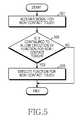
- FIG. 5 is a flowchart of a process of operating the host unit 110 for a non-contact touch signal.
- step 501 the host unit 110 receives a signal representing a non-contact touch from the proximity touch controller 330 .
- the present invention determines whether the host unit 110 is configured to allow the execution of a function for a non-contact touch. For example, a user may predetermine and set the terminal 10 not to execute the function for the non-contact touch, or alternatively, may predetermine and set the terminal 10 to execute the function for the non-contact touch.
- step 503 If it is determined in step 503 to allow the execution of the function for the non-contact touch, the method proceeds to step 505 , and the host unit 110 executes the function for the non-contact touch. The method of FIG. 5 then ends.
- step 503 if it is determined in step 503 not to allow the execution of the function for the non-contact touch, the host unit 110 does not execute the function for the non-contact touch, so the method skips step 505 , and then the method of FIG. 5 ends.
- the procedure of FIG. 5 is related to processing of a signal generated in the process of performing the present invention, in particular, step 409 of FIG. 4 , for a change from the configuration of sensing the non-contact touch to the configuration of sensing the contact touch of the exemplary embodiment of FIG. 4 .
- the host unit 110 executes a corresponding function for the contact touch in a manner known in the art for processing touch events on the touch screen device or unit 20 .
- FIGS. 6A-6C illustrate non-contact touch sensing according to the exemplary embodiment of the present invention. This is an example of generating an electric field by configuring a first x-electrode line 311 - 1 st and a last x-electrode line 311 -end of the electrostatic capacity touch panel 310 , as shown in FIG. 3 , as an Rx channel.
- the proximity touch sensing unit 300 configures the electrostatic capacity touch panel 310 as an Rx channel, and configures the shield layer 320 disposed below the electrostatic capacity touch panel 310 , spaced a specific predetermined distance D from the electrostatic capacity touch panel 310 , as a Tx channel.
- the electric field 350 for sensing a non-contact touch is formed, so that a user moving a hand, finger, or other member into the electric field 350 changes the capacitance and so is detected by the proximity touch controller 330 , which generates and transmits a corresponding electric signal to the host unit 110 , in a manner known in the art for touch screens.
- a capacitance (i.e., electrostatic capacity) shown in FIG. 6A is a projected capacitance represents energy related to the electric field 350 .
- the following aspects are preferably considered for optimal non-contact touch sensing.
- the capacitance is in proportion to a permittivity and an electrode area, and is in inverse proportion to a distance between two electrodes. Therefore, the number of electrode lines used to constitute the Rx channel in the electrostatic capacity touch panel 310 and specific positions of electrode lines 311 , 312 to be selected are used as values for determining the capacitance.
- the shield layer 320 which typically has a relatively wider area than that of an electrode of a typical touch panel, is configured as a Tx channel in the present invention, the capacitance can be increased. Further, a distance D between the electrostatic capacity touch panel 310 and the shield layer 320 is used as a value for determining the capacitance. The smaller the distance D is, the higher the capacitance is.
- the capacitance is decreased when the distance D between the electrostatic capacity touch panel 310 and the shield layer 320 is increased, since a variable quantity of the capacitance is small in regards to detecting proximity of a conductor, the variable quantity can be considered when determining sensitive non-contact touch sensing. That is, since relatively small changes in the capacitance may be detected using the present invention, relative spacing and sizing of components may be reduced without significant loss of detectable changes in the capacitance.
- a hand, finger, or other member of a user is brought to within a specific distance from the electrostatic capacity touch panel 310 , a variable quantity of a first capacitance is reduced, and reaches and drops below a first threshold F 1 , and the proximity touch controller 330 generates and transmits a signal representing a non-contact touch to the host unit 110 .
- the proximity touch controller 330 changes the shield layer 320 from an electric field generating electrode to a noise shielding ground, so that if the hand, finger, or other member is brought into contact with the electrostatic capacity touch panel 310 , the present invention senses a contact touch by generating an electric field by using only the electrostatic capacity touch panel 310 .
- FIGS. 7A-7B illustrate contact touch sensing according to the exemplary embodiment of the present invention.
- the proximity touch controller 330 If an electric field is generated by using the electrostatic capacity touch panel 310 and the shield layer 320 , as shown in FIG. 6A , and a variable quantity of a first capacitance is reduced by the presence of a conducting member, such as a finger, and the variable quantity reaches a second threshold F 2 , as shown in FIG. 6C , the proximity touch controller 330 generates an electric field by using x-electrodes 311 and y-electrodes 312 of the electrostatic capacity touch panel 310 , as shown in FIG. 3 , and changes the shield layer 320 from an electric field forming electrode to a noise shielding ground, as shown in FIG. 7A .
- a variable quantity of a second capacitance of the electrostatic capacity touch panel 310 is greater than or equal to a third threshold F 3 , and the proximity touch controller 330 generates and transmits a signal representing the contact touch to the host unit 110 .
- the switching between non-contact touch sensing and contact touch sensing is reversible, so that as the user moves a hand, finger, or other conducting member off of and away from the electrostatic capacity touch panel 310 , the proximity touch controller 330 senses changes in the variable quantities of the first and second capacitances being below or above the appropriate thresholds F 1 , F 2 , F 3 to change the terminal 10 and/or its touch screen device or unit 20 from contact touch sensing to non-contact touch sensing, depending on the distance of the hand or other member from the surface of the electrostatic capacity touch panel 310 .
- FIG. 8 illustrates electrode lines selected as an Rx channel in the electrostatic capacity touch panel 310 for non-contact touch sensing according to the exemplary embodiment of the present invention.
- At least one electrode line of the electrostatic capacity touch panel 310 is selectively determined to form an optimal electrode line for non-contact touch sensing.
- a first x-electrode 311 - 1 st, a last x-electrode line 311 -end, a first y-electrode line 312 - 1 st, and a last y-electrode line 312 -end are selected to be an Rx channel deployed to an outermost part of the electrostatic capacity touch panel 310 , with the electrode lines 311 - 1 st, 311 -end, 312 - 1 st, and 312 -end depicted with additional shading in FIG. 8 to illustrate the Rx channel in the outermost part of the electrostatic capacity touch panel 310 .
- a proximity touch sensing apparatus and method implement a touch area of an electrostatic capacity touch panel as an area for non-contact touch sensing without being limited to simple proximity determination. Therefore, various proximity gestures, e.g., a palm recognition, a finger swiper, etc., can be detected.
- the present invention configures an electrostatic capacity touch panel and a shield layer for noise shielding of a display as an apparatus for generating an electric field. Therefore, electrode lines of the electrostatic capacity touch panel can be selectively used, and a distance between the electrostatic capacity touch panel and the shield layer can be regulated to generate an electric field for optimal non-contact touch sensing using projected capacitance.
- the present invention uses a shield layer for noise shielding of a pre-configured display as an apparatus for generating an electric field for non-contact touch sensing, which leads to cost reduction in fabricating the terminal 10 .
- the present invention can mutually change between contact-touch sensing and non-contact-touch sensing by using a touch screen, thereby increasing usability of the touch screen.
- the above-described apparatus and methods according to the present invention can be implemented in hardware or firmware, or as software or computer code, or combinations thereof
- the software or computer code can also be stored in a non-transitory recording medium such as a CD ROM, a RAM, a ROM whether erasable or rewritable or not, a floppy disk, CDs, DVDs, memory chips, a hard disk, a magnetic storage media, an optical recording media, or a magneto-optical disk or computer code downloaded over a network originally stored on a remote recording medium, a computer readable recording medium, or a non-transitory machine readable medium and to be stored on a local recording medium, so that the methods described herein can be rendered in such software, computer code, software modules, software objects, instructions, applications, applets, apps, etc.
- the computer, the processor, microprocessor controller or the programmable hardware include volatile and/or non-volatile storage and memory components, e.g., RAM, ROM, Flash, etc. that may store or receive software or computer code that when accessed and executed by the computer, processor or hardware implement the processing methods described herein.
- volatile and/or non-volatile storage and memory components e.g., RAM, ROM, Flash, etc.
- the execution of the code transforms the general purpose computer into a special purpose computer for executing the processing shown herein.
- the program may be electronically transferred through any medium such as communication signals transmitted by wire/wireless connections, and their equivalents.
- the programs and computer readable recording medium can also be distributed in network-coupled computer systems so that the computer readable code is stored and executed in a distributed fashion.
Landscapes
- Engineering & Computer Science (AREA)
- General Engineering & Computer Science (AREA)
- Theoretical Computer Science (AREA)
- Human Computer Interaction (AREA)
- Physics & Mathematics (AREA)
- General Physics & Mathematics (AREA)
- Computer Networks & Wireless Communication (AREA)
- Position Input By Displaying (AREA)
- Switches That Are Operated By Magnetic Or Electric Fields (AREA)
- User Interface Of Digital Computer (AREA)
Applications Claiming Priority (2)
| Application Number | Priority Date | Filing Date | Title |
|---|---|---|---|
| KR10-2012-0064437 | 2012-06-15 | ||
| KR1020120064437A KR101925485B1 (ko) | 2012-06-15 | 2012-06-15 | 근접 터치 감지 장치 및 방법 |
Publications (2)
| Publication Number | Publication Date |
|---|---|
| US20130335370A1 US20130335370A1 (en) | 2013-12-19 |
| US9223450B2 true US9223450B2 (en) | 2015-12-29 |
Family
ID=48672394
Family Applications (1)
| Application Number | Title | Priority Date | Filing Date |
|---|---|---|---|
| US13/912,345 Active 2033-11-10 US9223450B2 (en) | 2012-06-15 | 2013-06-07 | Apparatus and method for proximity touch sensing |
Country Status (10)
| Country | Link |
|---|---|
| US (1) | US9223450B2 (zh) |
| EP (1) | EP2674843B1 (zh) |
| JP (1) | JP2015523656A (zh) |
| KR (1) | KR101925485B1 (zh) |
| CN (1) | CN104364745B (zh) |
| AU (1) | AU2013275031B2 (zh) |
| BR (1) | BR112014031320A2 (zh) |
| CA (1) | CA2874122A1 (zh) |
| RU (1) | RU2014150601A (zh) |
| WO (1) | WO2013187670A1 (zh) |
Cited By (3)
| Publication number | Priority date | Publication date | Assignee | Title |
|---|---|---|---|---|
| US20150370384A1 (en) * | 2014-06-20 | 2015-12-24 | Samsung Electronics Co., Ltd. | Electronic device using electromagnetic field for user input |
| US10528172B2 (en) | 2016-06-17 | 2020-01-07 | Microsoft Technology Licensing, Llc | Pressure sensor for display devices |
| US11796587B2 (en) | 2020-04-03 | 2023-10-24 | Samsung Electronics Co., Ltd. | Defect detection structures, semiconductor devices including the same, and methods of detecting defects in semiconductor dies |
Families Citing this family (23)
| Publication number | Priority date | Publication date | Assignee | Title |
|---|---|---|---|---|
| US8717325B1 (en) | 2013-02-18 | 2014-05-06 | Atmel Corporation | Detecting presence of an object in the vicinity of a touch interface of a device |
| JP6133732B2 (ja) * | 2013-09-04 | 2017-05-24 | アルプス電気株式会社 | 入力装置及びその検出方法 |
| WO2015108112A1 (ja) * | 2014-01-15 | 2015-07-23 | 株式会社Juice Design | 操作判定装置、操作判定方法、および、プログラム |
| KR101585929B1 (ko) | 2014-02-04 | 2016-01-15 | 어보브반도체 주식회사 | 근접 터치 방지용 터치 키 모듈 및 근접 터치 방지 방법 |
| US9164640B2 (en) | 2014-02-28 | 2015-10-20 | Cypress Semiconductor Corporation | Barrier electrode driven by an excitation signal |
| US9354734B2 (en) * | 2014-03-04 | 2016-05-31 | Atmel Corporation | Common-mode hover detection |
| US9927933B2 (en) * | 2014-07-10 | 2018-03-27 | Microchip Technology Germany Gmbh | Method and system for gesture detection and touch detection |
| EP2988479B1 (en) * | 2014-08-19 | 2019-01-30 | Semtech Corporation | Capacitive proximity sensor and mobile device |
| US9864464B2 (en) * | 2014-10-31 | 2018-01-09 | Semtech Corporation | Method and device for reducing radio frequency interference of proximity and touch detection in mobile devices |
| KR102350084B1 (ko) * | 2015-01-15 | 2022-01-11 | 삼성디스플레이 주식회사 | 터치 패널 및 이를 이용한 표시장치 |
| US9671913B2 (en) | 2015-05-11 | 2017-06-06 | Microsoft Technology Licensing, Llc | Capacitive display device |
| WO2017017800A1 (ja) | 2015-07-29 | 2017-02-02 | 株式会社ワコム | 座標入力装置 |
| CN106249899A (zh) * | 2016-08-15 | 2016-12-21 | 珠海格力电器股份有限公司 | 一种手势识别系统、电器及其控制方法 |
| JP6815812B2 (ja) * | 2016-10-04 | 2021-01-20 | 株式会社ジャパンディスプレイ | 表示装置 |
| DE102017000441A1 (de) | 2017-01-19 | 2018-07-19 | e.solutions GmbH | Eingabevorrichtung und Verfahren zum Erfassen einer Eingabe |
| CN112470106A (zh) * | 2018-06-22 | 2021-03-09 | 深圳市柔宇科技股份有限公司 | 手写感应装置及其低功耗控制电路、方法 |
| CN109656430A (zh) * | 2019-01-16 | 2019-04-19 | 汕头超声显示器技术有限公司 | 一种具有接近探测功能的电容触摸屏 |
| KR102276062B1 (ko) * | 2019-10-10 | 2021-07-12 | 주식회사 지니틱스 | 저소비전력으로 프록시미티 터치 입력을 검출하는 방법 및 이를 위한 장치 |
| JP7289781B2 (ja) * | 2019-12-19 | 2023-06-12 | アルパイン株式会社 | 液晶表示装置 |
| CN115485646A (zh) * | 2020-03-26 | 2022-12-16 | 华为技术有限公司 | 电容传感器、电子设备以及电子设备的控制方法 |
| CN111309188B (zh) * | 2020-04-02 | 2023-11-17 | 深圳创维-Rgb电子有限公司 | 触摸按键的屏蔽方法、装置和电容式触摸设备 |
| CN112148151B (zh) * | 2020-09-30 | 2023-06-13 | 天马微电子股份有限公司 | 显示面板、显示装置及触控方法 |
| WO2022174455A1 (zh) * | 2021-02-22 | 2022-08-25 | 华为技术有限公司 | 电容传感器、终端设备、传感器组件和检测方法 |
Citations (11)
| Publication number | Priority date | Publication date | Assignee | Title |
|---|---|---|---|---|
| US20050236906A1 (en) | 2003-09-04 | 2005-10-27 | Morgan Michael J | Electrical touch/proximity switch |
| US20100120473A1 (en) | 2008-11-12 | 2010-05-13 | Lg Electronics Inc. | Touch module, fabrication method thereof, and mobile terminal having the same |
| US20110007021A1 (en) * | 2009-07-10 | 2011-01-13 | Jeffrey Traer Bernstein | Touch and hover sensing |
| US20110063247A1 (en) | 2008-01-29 | 2011-03-17 | Dongjin Min | Touch sensing apparatus with parasitic capacitance prevention structure |
| US20110279410A1 (en) | 2009-02-13 | 2011-11-17 | Sang Hyun Han | Touch screen input apparatus |
| EP2418573A2 (en) | 2010-08-13 | 2012-02-15 | Samsung Electronics Co., Ltd. | Display apparatus and method for moving displayed object |
| US20120146943A1 (en) * | 2009-09-03 | 2012-06-14 | Koninklijke Philips Electronics N.V. | Touch sensing output device |
| US20130015868A1 (en) * | 2011-07-15 | 2013-01-17 | Cypress Semiconductor Corporation | Capacitance sensing circuits, methods and systems having ground insertion electrodes |
| US20130033450A1 (en) * | 2011-08-01 | 2013-02-07 | Sharp Kabushiki Kaisha | Dual mode capacitive touch panel |
| US20130162517A1 (en) * | 2011-12-22 | 2013-06-27 | Kenneth W. Gay | Gesturing Architecture Using Proximity Sensing |
| US20140152621A1 (en) * | 2011-11-11 | 2014-06-05 | Panasonic Corporation | Touch-panel device |
Family Cites Families (11)
| Publication number | Priority date | Publication date | Assignee | Title |
|---|---|---|---|---|
| JP2009175784A (ja) * | 2008-01-21 | 2009-08-06 | Mitsubishi Electric Corp | タッチパネル装置 |
| JP5176108B2 (ja) * | 2008-05-16 | 2013-04-03 | 株式会社フジクラ | 位置検出装置 |
| EP2435894A1 (en) * | 2009-05-27 | 2012-04-04 | Koninklijke Philips Electronics N.V. | Touch- or proximity-sensitive interface |
| TWI419028B (zh) * | 2009-10-07 | 2013-12-11 | Wintek Corp | 觸控面板與其應用之觸控式顯示裝置 |
| KR101623008B1 (ko) * | 2009-10-23 | 2016-05-31 | 엘지전자 주식회사 | 이동 단말기 |
| TW201140411A (en) * | 2010-01-13 | 2011-11-16 | Alps Electric Co Ltd | Capacitive proximity sensor device and electronic device using the same |
| US9189093B2 (en) * | 2010-02-10 | 2015-11-17 | Microchip Technology Germany Gmbh | System and method for the generation of a signal correlated with a manual input operation |
| CN102279678A (zh) * | 2010-06-12 | 2011-12-14 | 宸鸿科技(厦门)有限公司 | 触控电路图形结构及制造方法、触控面板及触控显示屏 |
| KR101733485B1 (ko) * | 2010-06-15 | 2017-05-10 | 엘지전자 주식회사 | 터치 패널 및 이를 포함하는 이동 단말기 |
| KR20130108556A (ko) * | 2010-08-23 | 2013-10-04 | 사이프레스 세미컨덕터 코포레이션 | 컨패시턴스 스캐닝 근접성 검출 |
| JP5773617B2 (ja) * | 2010-11-02 | 2015-09-02 | キヤノン株式会社 | 表示制御装置及び表示制御方法 |
-
2012
- 2012-06-15 KR KR1020120064437A patent/KR101925485B1/ko active IP Right Grant
-
2013
- 2013-06-07 US US13/912,345 patent/US9223450B2/en active Active
- 2013-06-11 AU AU2013275031A patent/AU2013275031B2/en not_active Ceased
- 2013-06-11 CN CN201380031547.1A patent/CN104364745B/zh active Active
- 2013-06-11 JP JP2015517179A patent/JP2015523656A/ja active Pending
- 2013-06-11 CA CA2874122A patent/CA2874122A1/en not_active Abandoned
- 2013-06-11 RU RU2014150601A patent/RU2014150601A/ru not_active Application Discontinuation
- 2013-06-11 BR BR112014031320A patent/BR112014031320A2/pt not_active Application Discontinuation
- 2013-06-11 WO PCT/KR2013/005139 patent/WO2013187670A1/en active Application Filing
- 2013-06-13 EP EP13171857.9A patent/EP2674843B1/en active Active
Patent Citations (11)
| Publication number | Priority date | Publication date | Assignee | Title |
|---|---|---|---|---|
| US20050236906A1 (en) | 2003-09-04 | 2005-10-27 | Morgan Michael J | Electrical touch/proximity switch |
| US20110063247A1 (en) | 2008-01-29 | 2011-03-17 | Dongjin Min | Touch sensing apparatus with parasitic capacitance prevention structure |
| US20100120473A1 (en) | 2008-11-12 | 2010-05-13 | Lg Electronics Inc. | Touch module, fabrication method thereof, and mobile terminal having the same |
| US20110279410A1 (en) | 2009-02-13 | 2011-11-17 | Sang Hyun Han | Touch screen input apparatus |
| US20110007021A1 (en) * | 2009-07-10 | 2011-01-13 | Jeffrey Traer Bernstein | Touch and hover sensing |
| US20120146943A1 (en) * | 2009-09-03 | 2012-06-14 | Koninklijke Philips Electronics N.V. | Touch sensing output device |
| EP2418573A2 (en) | 2010-08-13 | 2012-02-15 | Samsung Electronics Co., Ltd. | Display apparatus and method for moving displayed object |
| US20130015868A1 (en) * | 2011-07-15 | 2013-01-17 | Cypress Semiconductor Corporation | Capacitance sensing circuits, methods and systems having ground insertion electrodes |
| US20130033450A1 (en) * | 2011-08-01 | 2013-02-07 | Sharp Kabushiki Kaisha | Dual mode capacitive touch panel |
| US20140152621A1 (en) * | 2011-11-11 | 2014-06-05 | Panasonic Corporation | Touch-panel device |
| US20130162517A1 (en) * | 2011-12-22 | 2013-06-27 | Kenneth W. Gay | Gesturing Architecture Using Proximity Sensing |
Cited By (4)
| Publication number | Priority date | Publication date | Assignee | Title |
|---|---|---|---|---|
| US20150370384A1 (en) * | 2014-06-20 | 2015-12-24 | Samsung Electronics Co., Ltd. | Electronic device using electromagnetic field for user input |
| US9715317B2 (en) * | 2014-06-20 | 2017-07-25 | Samsung Electronics Co., Ltd. | Electronic device using electromagnetic field for user input |
| US10528172B2 (en) | 2016-06-17 | 2020-01-07 | Microsoft Technology Licensing, Llc | Pressure sensor for display devices |
| US11796587B2 (en) | 2020-04-03 | 2023-10-24 | Samsung Electronics Co., Ltd. | Defect detection structures, semiconductor devices including the same, and methods of detecting defects in semiconductor dies |
Also Published As
| Publication number | Publication date |
|---|---|
| EP2674843A2 (en) | 2013-12-18 |
| EP2674843A3 (en) | 2017-08-30 |
| AU2013275031B2 (en) | 2016-02-18 |
| AU2013275031A1 (en) | 2015-01-15 |
| BR112014031320A2 (pt) | 2017-06-27 |
| CN104364745A (zh) | 2015-02-18 |
| RU2014150601A (ru) | 2016-07-10 |
| EP2674843B1 (en) | 2020-08-05 |
| WO2013187670A1 (en) | 2013-12-19 |
| CA2874122A1 (en) | 2013-12-19 |
| US20130335370A1 (en) | 2013-12-19 |
| KR101925485B1 (ko) | 2019-02-27 |
| JP2015523656A (ja) | 2015-08-13 |
| CN104364745B (zh) | 2017-04-05 |
| KR20130141209A (ko) | 2013-12-26 |
Similar Documents
| Publication | Publication Date | Title |
|---|---|---|
| US9223450B2 (en) | Apparatus and method for proximity touch sensing | |
| RU2687037C1 (ru) | Способ, устройство быстрого разделения экрана, электронное устройство, ui отображения и носитель хранения | |
| US9460689B2 (en) | Mobile terminal and method for controlling the same | |
| JP6033502B2 (ja) | タッチ入力制御方法、タッチ入力制御装置、プログラム及び記録媒体 | |
| KR102081817B1 (ko) | 디지타이저 모드 전환 방법 | |
| EP2940572A1 (en) | Method and electronic device for managing display objects | |
| US20150077362A1 (en) | Terminal with fingerprint reader and method for processing user input through fingerprint reader | |
| EP3678017A1 (en) | Method and apparatus for outputting contents using a plurality of displays | |
| KR102182319B1 (ko) | 전자 기기 및 전자 기기에서 배터리 정보 제공 방법 | |
| EP3000016B1 (en) | User input using hovering input | |
| CN105094616B (zh) | 触摸屏控制方法及装置 | |
| US20170083148A1 (en) | Mobile terminal and method for controlling the same | |
| EP2787414B1 (en) | Method of controlling touch screen and electronic device thereof | |
| KR20180120768A (ko) | 사람-기계 상호작용 방법, 장치 및 그래픽 사용자 인터페이스 | |
| CA2846482A1 (en) | Method of providing of user interface in portable terminal and apparatus thereof | |
| KR20140125671A (ko) | 입력 제어 방법 및 이를 지원하는 전자 장치 | |
| CN106250034A (zh) | 一种窗口切换的方法及终端 | |
| KR20130097331A (ko) | 터치 스크린을 구비하는 전자기기에서 객체를 선택하기 위한 장치 및 방법 | |
| US20150346989A1 (en) | User interface for application and device | |
| EP2677413B1 (en) | Method for improving touch recognition and electronic device thereof | |
| US20140047370A1 (en) | Method and apparatus for copy-and-paste of object | |
| KR102185204B1 (ko) | 적외선을 이용한 센서 장치를 갖는 전자 장치 및 그 동작 방법 | |
| KR102158293B1 (ko) | 이미지 촬영 방법 및 그 전자 장치 | |
| KR20130115693A (ko) | 확대 이미지를 제공하기 위한 방법 및 그 전자 장치 | |
| KR20150026395A (ko) | 이미지 촬영 방법 및 그 전자 장치 |
Legal Events
| Date | Code | Title | Description |
|---|---|---|---|
| AS | Assignment |
Owner name: SAMSUNG ELECTRONICS CO., LTD., KOREA, REPUBLIC OF Free format text: ASSIGNMENT OF ASSIGNORS INTEREST;ASSIGNORS:HEO, HOON-DO;PARK, JAE-WOOK;PARK, JONG-DAE;AND OTHERS;REEL/FRAME:030566/0061 Effective date: 20130603 |
|
| FEPP | Fee payment procedure |
Free format text: PAYOR NUMBER ASSIGNED (ORIGINAL EVENT CODE: ASPN); ENTITY STATUS OF PATENT OWNER: LARGE ENTITY |
|
| STCF | Information on status: patent grant |
Free format text: PATENTED CASE |
|
| MAFP | Maintenance fee payment |
Free format text: PAYMENT OF MAINTENANCE FEE, 4TH YEAR, LARGE ENTITY (ORIGINAL EVENT CODE: M1551); ENTITY STATUS OF PATENT OWNER: LARGE ENTITY Year of fee payment: 4 |
|
| MAFP | Maintenance fee payment |
Free format text: PAYMENT OF MAINTENANCE FEE, 8TH YEAR, LARGE ENTITY (ORIGINAL EVENT CODE: M1552); ENTITY STATUS OF PATENT OWNER: LARGE ENTITY Year of fee payment: 8 |