US9212723B2 - Pneumatic liquid on-line automatic balancer of rotor - Google Patents
Pneumatic liquid on-line automatic balancer of rotor Download PDFInfo
- Publication number
- US9212723B2 US9212723B2 US14/370,049 US201214370049A US9212723B2 US 9212723 B2 US9212723 B2 US 9212723B2 US 201214370049 A US201214370049 A US 201214370049A US 9212723 B2 US9212723 B2 US 9212723B2
- Authority
- US
- United States
- Prior art keywords
- balancing
- rotor
- chambers
- channel
- central
- Prior art date
- Legal status (The legal status is an assumption and is not a legal conclusion. Google has not performed a legal analysis and makes no representation as to the accuracy of the status listed.)
- Expired - Fee Related
Links
- 239000007788 liquid Substances 0.000 title claims abstract description 133
- 238000012546 transfer Methods 0.000 claims abstract description 22
- 238000004891 communication Methods 0.000 claims description 60
- 238000002347 injection Methods 0.000 claims description 21
- 239000007924 injection Substances 0.000 claims description 21
- 238000000034 method Methods 0.000 description 5
- 238000013461 design Methods 0.000 description 3
- 238000003466 welding Methods 0.000 description 3
- 239000006096 absorbing agent Substances 0.000 description 2
- 230000035939 shock Effects 0.000 description 2
- 208000036829 Device dislocation Diseases 0.000 description 1
- GYHNNYVSQQEPJS-UHFFFAOYSA-N Gallium Chemical compound [Ga] GYHNNYVSQQEPJS-UHFFFAOYSA-N 0.000 description 1
- 230000003247 decreasing effect Effects 0.000 description 1
- 238000005553 drilling Methods 0.000 description 1
- 239000000428 dust Substances 0.000 description 1
- 230000000694 effects Effects 0.000 description 1
- NBVXSUQYWXRMNV-UHFFFAOYSA-N fluoromethane Chemical compound FC NBVXSUQYWXRMNV-UHFFFAOYSA-N 0.000 description 1
- 229910052733 gallium Inorganic materials 0.000 description 1
- 238000009434 installation Methods 0.000 description 1
- 230000003993 interaction Effects 0.000 description 1
- 238000003754 machining Methods 0.000 description 1
- 238000012986 modification Methods 0.000 description 1
- 230000004048 modification Effects 0.000 description 1
- 229920002545 silicone oil Polymers 0.000 description 1
- 239000000243 solution Substances 0.000 description 1
- XLYOFNOQVPJJNP-UHFFFAOYSA-N water Substances O XLYOFNOQVPJJNP-UHFFFAOYSA-N 0.000 description 1
Images


Classifications
-
- F—MECHANICAL ENGINEERING; LIGHTING; HEATING; WEAPONS; BLASTING
- F16—ENGINEERING ELEMENTS AND UNITS; GENERAL MEASURES FOR PRODUCING AND MAINTAINING EFFECTIVE FUNCTIONING OF MACHINES OR INSTALLATIONS; THERMAL INSULATION IN GENERAL
- F16F—SPRINGS; SHOCK-ABSORBERS; MEANS FOR DAMPING VIBRATION
- F16F15/00—Suppression of vibrations in systems; Means or arrangements for avoiding or reducing out-of-balance forces, e.g. due to motion
- F16F15/10—Suppression of vibrations in rotating systems by making use of members moving with the system
- F16F15/16—Suppression of vibrations in rotating systems by making use of members moving with the system using a fluid or pasty material
- F16F15/161—Suppression of vibrations in rotating systems by making use of members moving with the system using a fluid or pasty material characterised by the fluid damping devices, e.g. passages, orifices
-
- B—PERFORMING OPERATIONS; TRANSPORTING
- B23—MACHINE TOOLS; METAL-WORKING NOT OTHERWISE PROVIDED FOR
- B23Q—DETAILS, COMPONENTS, OR ACCESSORIES FOR MACHINE TOOLS, e.g. ARRANGEMENTS FOR COPYING OR CONTROLLING; MACHINE TOOLS IN GENERAL CHARACTERISED BY THE CONSTRUCTION OF PARTICULAR DETAILS OR COMPONENTS; COMBINATIONS OR ASSOCIATIONS OF METAL-WORKING MACHINES, NOT DIRECTED TO A PARTICULAR RESULT
- B23Q11/00—Accessories fitted to machine tools for keeping tools or parts of the machine in good working condition or for cooling work; Safety devices specially combined with or arranged in, or specially adapted for use in connection with, machine tools
- B23Q11/0032—Arrangements for preventing or isolating vibrations in parts of the machine
- B23Q11/0035—Arrangements for preventing or isolating vibrations in parts of the machine by adding or adjusting a mass, e.g. counterweights
-
- F—MECHANICAL ENGINEERING; LIGHTING; HEATING; WEAPONS; BLASTING
- F16—ENGINEERING ELEMENTS AND UNITS; GENERAL MEASURES FOR PRODUCING AND MAINTAINING EFFECTIVE FUNCTIONING OF MACHINES OR INSTALLATIONS; THERMAL INSULATION IN GENERAL
- F16F—SPRINGS; SHOCK-ABSORBERS; MEANS FOR DAMPING VIBRATION
- F16F15/00—Suppression of vibrations in systems; Means or arrangements for avoiding or reducing out-of-balance forces, e.g. due to motion
- F16F15/10—Suppression of vibrations in rotating systems by making use of members moving with the system
- F16F15/16—Suppression of vibrations in rotating systems by making use of members moving with the system using a fluid or pasty material
- F16F15/167—Suppression of vibrations in rotating systems by making use of members moving with the system using a fluid or pasty material having an inertia member, e.g. ring
- F16F15/173—Suppression of vibrations in rotating systems by making use of members moving with the system using a fluid or pasty material having an inertia member, e.g. ring provided within a closed housing
-
- F—MECHANICAL ENGINEERING; LIGHTING; HEATING; WEAPONS; BLASTING
- F16—ENGINEERING ELEMENTS AND UNITS; GENERAL MEASURES FOR PRODUCING AND MAINTAINING EFFECTIVE FUNCTIONING OF MACHINES OR INSTALLATIONS; THERMAL INSULATION IN GENERAL
- F16F—SPRINGS; SHOCK-ABSORBERS; MEANS FOR DAMPING VIBRATION
- F16F15/00—Suppression of vibrations in systems; Means or arrangements for avoiding or reducing out-of-balance forces, e.g. due to motion
- F16F15/32—Correcting- or balancing-weights or equivalent means for balancing rotating bodies, e.g. vehicle wheels
- F16F15/322—Correcting- or balancing-weights or equivalent means for balancing rotating bodies, e.g. vehicle wheels the rotating body being a shaft
-
- G—PHYSICS
- G01—MEASURING; TESTING
- G01M—TESTING STATIC OR DYNAMIC BALANCE OF MACHINES OR STRUCTURES; TESTING OF STRUCTURES OR APPARATUS, NOT OTHERWISE PROVIDED FOR
- G01M1/00—Testing static or dynamic balance of machines or structures
- G01M1/30—Compensating imbalance
- G01M1/32—Compensating imbalance by adding material to the body to be tested, e.g. by correcting-weights
- G01M1/323—Compensating imbalance by adding material to the body to be tested, e.g. by correcting-weights using balancing liquid
-
- G—PHYSICS
- G01—MEASURING; TESTING
- G01M—TESTING STATIC OR DYNAMIC BALANCE OF MACHINES OR STRUCTURES; TESTING OF STRUCTURES OR APPARATUS, NOT OTHERWISE PROVIDED FOR
- G01M1/00—Testing static or dynamic balance of machines or structures
- G01M1/30—Compensating imbalance
- G01M1/36—Compensating imbalance by adjusting position of masses built-in the body to be tested
- G01M1/365—Compensating imbalance by adjusting position of masses built-in the body to be tested using balancing liquid
-
- Y—GENERAL TAGGING OF NEW TECHNOLOGICAL DEVELOPMENTS; GENERAL TAGGING OF CROSS-SECTIONAL TECHNOLOGIES SPANNING OVER SEVERAL SECTIONS OF THE IPC; TECHNICAL SUBJECTS COVERED BY FORMER USPC CROSS-REFERENCE ART COLLECTIONS [XRACs] AND DIGESTS
- Y10—TECHNICAL SUBJECTS COVERED BY FORMER USPC
- Y10T—TECHNICAL SUBJECTS COVERED BY FORMER US CLASSIFICATION
- Y10T74/00—Machine element or mechanism
- Y10T74/21—Elements
- Y10T74/2121—Flywheel, motion smoothing-type
- Y10T74/2122—Flywheel, motion smoothing-type with fluid balancing means
Definitions
- the present invention relates to a shock absorber, in particular to an automatic shock absorber for a rotating device.
- On-line automatic balance is the best scheme for improving the balance level of the rotating system and reducing the vibration.
- an automatic balance actuator of rotating machinery mainly involves two kinds of products: an electromagnetically mechanical balance actuator and a liquid injection-balance actuator.
- the liquid injection-balance actuator has a simple structure. However, the actuator has less balance capability as the number of the balance increased, without shutdown hold function, so that liquid is required to be injected into the chamber rotating at high speed, and there is more uncertainty in terms of injection volume and the splash also has a certain influence on the surroundings. Because there is difficult to isolate the injection process from the surroundings, dust and other foreign matter are easy to be brought in and there is resistance change in the injection hole with small aperture, resulting in the decreased system control performance and even out of control.
- the present invention provides a pneumatic liquid on-line automatic balancer of a rotor which is of permanent balance ability and is suitable for a high-speed rotating device.
- a pneumatic liquid on-line automatic balancer of a rotor includes a sealed balancing disk rotating with a balanced rotor about a central axis and a pressure transfer device mated with the sealed balancing disk. At least two pairs of centrosymmetric chamber filled with appropriate balancing liquid are evenly distributed in the sealed balancing disk.
- the pressure transfer device controls compressed gas in and out of the chamber and makes the balancing liquid controllably flow in each pair of the chambers to achieve dynamic balance of the rotor.
- a communicating channel of the balancing liquid is provided between outer edges of each pair of the chambers.
- the communicating channel of the balancing liquid is one and a center of the communicating channel of the balancing liquid is communicated with the balancing channel pointed to a center of rotation. Another end of the balancing channel is communicated with an emptying channel axially located near the center of rotation. Another end of the emptying channel is opened to atmosphere.
- the chambers in the sealed balancing disk are two pairs, the first and the third chambers are formed into one pair in which the communicating channel of the balancing liquid is a first communicating tube, and the second and the fourth chamber are formed into the other pair in which the communicating channel of the balancing liquid is a second communicating tube, the balancing channels are respectively a first and a second balancing tubes and the emptying channels are respectively a first and a second emptying tubes.
- the pressure transfer device includes a gas distributor, two position three way electromagnetic valves and a gas source which are communicated in turn.
- the gas distributor includes a central rotor, a middle sleeve and an outer stator.
- the outer stator is provided in a body of the balancing disk with a space between them.
- the middle sleeve and the central rotor are installed in an inner wall of the outer stator in turn with a gap between the middle sleeve and the central rotor.
- Two bearings are respectively arranged at ends of the middle sleeve and an outer race and an inner race of the above bearing is tight fitted with the inner wall of the outer stator and an outer wall of the central rotor respectively.
- a first, a second, a third and a fourth radial inlet channels are provided in an outer wall of the outer stator.
- the four radial inlet channels are arranged in the outer stator in an axial direction in turn and connected to first ends of a first, a second, a third and a fourth inlet pipes, respectively. Second ends of the four inlet pipes are connected to the gas source, respectively.
- the two position three way electromagnetic valve is provided in each of the four inlet pipes.
- each axial inlet channel is provided in different radial angle positions of the central rotor and four circumferential gas inlet grooves are provided in the outer wall of the central rotor.
- One end of each axial inlet channel is respectively communicated with one of the corresponding circumferential gas inlet grooves through one radial hole and another end is communicated with a corresponding inlet branch.
- In an inner wall of each chamber is formed one inlet channel through which each the inlet branch is communicated with the corresponding chamber.
- Each the inlet branch is connected to a body of the balancing disk through a pipe joint.
- the middle sleeve In the axial direction, the middle sleeve is provided with four vents in turn, one end of which is communicated with the four corresponding circumferential gas inlet groove respectively and the other end of which is communicated with the first, the second, the third and the fourth axial inlet channels respectively.
- the first and the second emptying tubes have a same structure, in which the first emptying tube includes an axial emptying section and a radial emptying section connected with each other and located in the central rotor, a radial emptying section located in the central sleeve and a radial emptying section located in the outer stator.
- the radial emptying section in the outer stator is opened to the atmosphere.
- the sealed balancing disk includes a body of the balancing disk and a cover hermetically sealed with the body of the balancing disk.
- the chambers are formed into two pairs and include a first, a second, a third and a fourth chambers.
- the first and the third chambers are formed into one pair and the second and the fourth chamber are formed into the other pair.
- the pressure transfer device includes a gas distributor, two position three way electromagnetic valves and a gas source which are pneumatically communicated in turn.
- the gas distributor includes a central stator and a middle sleeve.
- the central stator is arranged in a central hole in the body of the balancing disk and the middle sleeve is arranged between the central stator and the body of the balancing disk. There is a tight fit between the middle sleeve and a wall of the central hole and there is a gap between the middle sleeve and the central stator.
- Two bearings are respectively arranged at both ends of the middle sleeve. There is a tight fit between an outer race of the bearing and the wall of the central hole as well as between an inner race of the bearing and the central stator.
- a first, a second, a third and a fourth axial inlet channels are provided in the central stator and four circumferentially distributed annular grooves are provided in an outer wall of the central stator. First ends of the four axial inlet channels are respectively communicated with the annular groove through a radial vent.
- An injection tube is provided in the inner wall of each chamber and in an outer surface of the middle sleeve is provided with four axial grooves, one end of which is communicated with the injection tubes of the four chambers respectively and the other end of which is communicated with the annual groove in the central stator through the vent.
- the vents in the middle sleeve are provided at the ends of the axial grooves respectively and passed through the middle sleeve.
- Second ends of the first, the second, the third and the fourth axial inlet channels are connected to the gas source through a supply pipe, respectively.
- the two position three way electromagnetic valve is provided in each of the supply pipes.
- a central hole is provided in the cover and the cover comprises a left, a right and a middle plate fixed together in turn.
- a second balancing liquid communication channel and a second balancing channel of the second and the fourth chamber are provided in a right side of the left plate, and a first balancing liquid communication channel and a first balancing channel of the first and the third chambers are provided in a left side of the right plate.
- the centers of the first and the second balancing liquid communication channels are respectively connected with the first and the second balancing channels.
- a first and a second emptying channels are also provided in the cover, the second emptying channel is opened to the atmosphere through the right plate and the middle plate and the first emptying channel is opened to the atmosphere through the right plate. Another ends of the first and the second balancing channels are communicated with the first and the second emptying channels respectively.
- the sealed balancing disk includes a body of the balancing disk and a cover fixed by each other.
- the pressure transfer device includes a gas distributor, two position three way electromagnetic valves and a gas source which are pneumatically communicated in turn.
- the gas distributor is located at an axial outside of the sealed balancing disk and comprises a central rotor, a middle sleeve and an outer stator.
- the outer stator is sleeved on the central rotor and the middle sleeve is located between the central rotor and the outer stator.
- the cover is made into three layers and includes a left plate, a right plate and a middle plate hermetically sealed by each other.
- the right plate is integrated with the central rotor.
- the balancing liquid communication channel between the second and the fourth chambers is the second communication channel in a right side of the left plate and the balancing liquid communication channel between the first and the third chambers is the first communication channel in a left side of the right plate.
- the balancing channels are the second balancing channel in the right side of the left plate and the first balancing channel in the left side of the right plate.
- In a left surface of the right plate are provided with four injection channels, one end of which is respectively communicated with the axial inlet channel in the central rotor and the other end of which is communicated with the four chambers through injection holes in the middle and the left plate respectively.
- the centers of the first and the second communication channels are respectively connected with first ends of the first and the second balancing channels. Second ends of the first and the second balancing channels are connected to a first and a second vents respectively.
- a first and a second axial extending emptying tubes are provided in the central rotor.
- the first vent is communicated with the first emptying tube through the right plate and the second vent is communicated with the second emptying tube through the right and the middle plates.
- the first vent and the first emptying tube form the first emptying channel and the second vent and the second emptying tube form the second emptying channel, and the first and the second communication channels are Venturi necking channels.
- the ends of the first and the second emptying tubes are both provided with a gas-permeable and anti-liquid plug.
- the first, the second, the third and the fourth chambers are sectors.
- the arc outer wall of each chamber is a conical surface outward leaned in the axial direction.
- the connections between the first communication channel and the first and the third chambers are respectively notched in the grooves in the arc outer walls of the first and the third chambers, and the connections between the second communication channel and the second and the fourth chambers are respectively notched in the grooves in the arc outer walls of the second and the fourth chambers.
- an alternative cover is made into four layers instead of three layers and includes a left plate, a middle plate, a first right plate and a second right plate, four injection channels are positioned in a right side of the left plate, a first communication channel is positioned in a left side of the first right plate, a second communication channel is positioned in a left side of the second right plate, and the first and the second communication channels are Venturi channels.
- the pneumatic liquid on-line automatic balancer of the rotor there are also five pressure-equalizing grooves in the central rotor, which are circumferential annular grooves provided in the outer wall of the central rotor, and the five pressure-equalizing grooves and the four gas inlet grooves are alternately distributed.
- the center of the balancing liquid communication channel is communicated with one end of the balancing channel pointed to the center of rotation, the other end of the balancing channel is connected to one end of the emptying channel and the other end of the emptying channel is opened to the atmosphere, the atmosphere can be drawn in through the emptying channel under negative pressure generated in the center of the balancing liquid communication channel after the compressed gas fed in the chamber is cut off, making directional flow of the balancing liquid in the balancing liquid communication channel to end.
- a function of the balancing channel is that, when the compressed gas is fed in the chamber and a pressure in the chamber has reached to a certain value, the balancing liquid would flow through the center of the balancing liquid communication channel and accelerate to the opposite chamber. Meanwhile, if the pressure of the balancing liquid in the center of the balancing liquid communication channel is below atmospheric pressure, a part of the balancing liquid would enter into the balancing channel and then generate a centrifugal force to prevent more the balancing liquid from entering the balancing channel, therefore leakage of the balancing liquid from the emptying channel is prevented, and the device is of a permanent balance ability and is suitable for a high-speed rotating device.
- the cover includes the left plate, the middle plate and the right plate, and the two balancing liquid communication channels and the two balancing channels are respectively provided in the left and the right plate, thus the pneumatic liquid on-line automatic balancer of the rotor according to the present invention has a simpler structure and is adaptable to a high-speed rotating condition better.
- the balancing liquid can be prevented from shooting under misoperation or a fault of a relief valve of the gas source, without the loss of the balancing liquid.
- a layer of the balancing liquid can be stuck to the outer annular wall of the chamber and can not to be used during high-speed rotation.
- the arc outer wall of the chamber is the conical surface outward leaned in the axial direction so that an inner diameter at an outlet of the balancing liquid communication channel is the maximum among those at all axial positions. Because of this, the balancing liquid can be concentrated near the outlet of the leaned outer edge when a few is left and a utilization ratio of the balancing liquid can be improved.
- each the gas inlet groove keeps relative independence without an interaction effect during gas injection process. Due to the small pressure relief hole, the annular pressure-equalizing groove plays a role in certainly increasing resistance of the gas leakage and keeps the gas inlet grooves in a same sealed environment.
- Position determination of all holes in the chamber is required to meet a requirement that there is no leakage of the balancing liquid to outside in the high-speed rotation and stationary states of the sealed balancing disk.
- the gap between the middle sleeve and the stator or the rotor of the pressure transfer device according to the present invention has a certain influence on pressure transmissibility; however, a flowing area of the inlet in the stator has more influence on the pressure transmissibility. Due to usage of a good inlet design and the appropriate gap, the pressure transmissibility can be up to 85%.
- FIG. 1 is a front sectional view of a pneumatic liquid on-line automatic balancer of a rotor according to embodiment 1 of the present invention
- FIG. 2 is a sectional view taken along the line A-A of FIG. 1 .
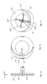
- FIG. 3 is a bottom view of the pneumatic liquid on-line automatic balancer of the rotor according to the embodiment 1 of the present invention
- FIG. 4 is an installation schematic of the pneumatic liquid on-line automatic balancer of the rotor according to the embodiment 1 of the present invention
- FIG. 5 is a front sectional view of the pneumatic liquid on-line automatic balancer of the rotor according to embodiment 2 of the present invention.
- FIG. 6 is a left view of a sealed balancing disk of the pneumatic liquid on-line automatic balance of the rotor according to the embodiment 2 of the present invention.
- FIG. 7 is a sectional view of a cover of the pneumatic liquid on-line automatic balancer of the rotor according to the embodiment 2 of the present invention.
- FIG. 8 is a left view of a left plate of the cover of the pneumatic liquid on-line automatic balancer of the rotor according to the embodiment 2 of the present invention.
- FIG. 9 is a right view of a middle plate of the cover of the pneumatic liquid on-line automatic balancer of the rotor according to the embodiment 2 of the present invention.
- FIG. 10 is a right view of a right plate of the cover of the pneumatic liquid on-line automatic balancer of the rotor according to the embodiment 2 of the present invention.
- FIG. 11 is a front sectional view of the pneumatic liquid on-line automatic balancer of the rotor according to embodiment 3 of the present invention.
- FIG. 12 is a front view of the cover of the pneumatic liquid on-line automatic balancer of the rotor according to the embodiment 3 of the present invention.
- FIG. 13 is a left view of the left plate of the cover of the pneumatic liquid on-line automatic balancer of the rotor according to the embodiment 3 of the present invention.
- FIG. 14 is a right view of the right plate of the cover of the pneumatic liquid on-line automatic balancer of the rotor according to the embodiment 3 of the present invention.
- FIG. 15 is a front view of an alternative cover of the pneumatic liquid on-line automatic balancer of the rotor according to the embodiment 3 of the present invention.
- FIG. 16 is a left view of a left plate of the alternative cover of the pneumatic liquid on-line automatic balancer of the rotor according to the embodiment 3 of the present invention.
- FIG. 17 is a right view of a first right plate of the alternative cover of the pneumatic liquid on-line automatic balancer of the rotor according to the embodiment 3 of the present invention.
- FIG. 18 is a right view of a second right plate of the alternative cover of the pneumatic liquid on-line automatic balancer of the rotor according to the embodiment 3 of the present invention.
- a pneumatic liquid on-line automatic balancer of a rotor includes a sealed balancing disk 1 and a pressure transfer device 9 .
- the pressure transfer device 9 includes a gas distributor 2 , two position three way electromagnetic valves and a gas source.
- the sealed balancing disk 1 includes a body 11 of the balancing disk and a cover 12 which is fixed in the body 11 of the balancing disk by bolts.
- a central hole 111 is provided in the body 11 of the balancing disk and a first, a second, a third and a fourth chambers 31 , 32 , 33 , 34 are uniformly formed between the central hole 111 and an outer wall of the body 11 of the balancing disk.
- the first and the third chambers 31 , 33 are formed into one symmetric pair and the second and the fourth chambers 32 , 34 are formed into the other symmetric pair.
- Each the chamber is filled with balancing liquid, whose volume is less than half of each chamber's volume.
- the balancing liquid can be water, silicone oil, fluorocarbon oil, liquid gallium and the like.
- a first communication tube 41 is provided between the first and the third chambers 31 , 33 and a second communication tube 42 is provided between the second and the fourth chambers 32 , 34 . Centers of the first and the second communication tubes 41 , 42 are respectively connected with the first and the second balancing tubes 51 , 52 .
- First ends of the first and the second balancing tubes 51 , 52 are pointed to a center of rotation and second ends are connected to first ends of a first and a second emptying tubes 61 , 62 axially located near the center of rotation. Second ends of the first and the second emptying tubes 61 , 62 are opened to atmosphere.
- the first and the second communication tubes 41 , 42 and the first and the second balancing tubes 51 , 52 are arranged outside of the sealed balancing disk 1 .
- the first communication tube 41 is the liquid channel between the first and the third chambers 31 , 33
- the second communication tube 42 is the liquid channel between the second and the fourth chambers 32 , 34
- the first and the second balancing tubes 51 , 52 form the balancing channel.
- the gas distributor 2 comprises a central rotor 21 , a middle sleeve 22 and an outer stator 23 .
- the outer stator 23 is provided in the central hole 111 in the body of the balancing disk with a space between the outer stator 23 and the body 11 of the balancing disk.
- the outer stator 23 is annular and an inner wall of the outer stator 23 is provided with the middle sleeve 22 and the central rotor 21 in turn with a gap between the middle sleeve 22 and the central rotor 21 .
- Two bearings are respectively arranged at two ends of the middle sleeve 22 and an outer race and an inner race of the above bearings are tightly fitted with the inner wall of the outer stator 23 and an outer wall of the central rotor 21 respectively.
- a first, a second, a third and a fourth radial inlet channels 231 , 232 , 233 , 234 are provided in an outer wall of the outer stator 23 .
- the four radial inlet channels are arranged in the outer stator 23 in an axial direction in turn and first ends of a first, a second, a third and a fourth inlet pipes 71 , 72 , 73 , 74 are connected to the first, the second, the third and the fourth radial inlet channels 231 , 232 , 233 , 234 , respectively.
- Four two position three way electromagnetic valves are provided in the first, the second, the third and the fourth inlet pipes 71 , 72 , 73 , 74 , respectively.
- Second ends of the first, the second, the third and the fourth inlet pipes 71 , 72 , 73 , 74 are connected to a gas source.
- Four axial inlet channels are provided in different radial angle positions of the central rotor 21 and four circumferential gas inlet grooves 211 , 212 , 213 , 214 are provided in the central rotor 21 .
- the gas inlet grooves are circumferential annular grooves provided in the outer wall of the central rotor 21 in turn.
- One end of each axial inlet channel is respectively communicated with the gas inlet groove through one radial hole and the other end is communicated with one inlet branch 711 .
- each the inlet branch is communicated with the first, the second, the third and the fourth chambers 31 , 32 , 33 , 34 through the inlet channel and connected to the sealed balancing disk 1 through a pipe joint, respectively.
- the middle sleeve 22 is provided with four vents 221 , 222 , 223 , 224 in turn, one end of which is communicated with the four gas inlet grooves 211 , 212 , 213 , 214 respectively and the other end of which is communicated with the first, the second, the third and the fourth radial inlet channels 231 , 232 , 233 , 234 respectively.
- the first and the second emptying tubes 61 , 62 have a same structure, as shown in FIG. 1 .
- the first emptying tube 62 includes an axial emptying section 215 and a radial emptying section 216 located in the central rotor 21 , a radial emptying section 225 located in the central sleeve 22 and a radial emptying section 235 located in the outer stator 23 .
- the radial emptying section 235 in the outer stator 23 is opened to the atmosphere.
- the pneumatic liquid on-line automatic balancer of the rotor is installed at a motorized spindle connecting rod 81 of a drilling machine 8 .
- the motorized spindle connecting rod 81 drives the sealed balancing disk 1 and the central rotor 21 to rotate together.
- a vibration sensor and a proximity switch are installed on the motorized spindle connecting rod 81 .
- the vibration sensor, the proximity switch and four two position three way electromagnetic valves are connected to an automatic balance controller, and a vibration waveforms signal is transmitted from the vibration sensor to the automatic balance controller.
- a keyway in the motorized spindle connecting rod 81 would pass over the proximity switch, the proximity switch would output a pulse to the automatic balance controller, a speed of the balanced rotor, an amplitude and phase data of unbalance are extracted from the measured signals of the vibration sensor and the proximity switch by the automatic balance controller, then a transfer object and a transfer quantity of balance control are accordingly calculated and an application time is used as a measure of the transfer quantity.
- the first chamber 31 should be transferred to the third chamber 33 for 2.2 second and the second chamber 32 should be transferred to the fourth chamber 34 for 5.4 second, hence, energization commands for 2.2 seconds and 5.4 seconds are respectively issued to the two position three way electromagnetic valves in the inlet pipes of the first and the second chambers.
- the compressed gas is leaded to the radial inlet channel in the outer stator 23 through the two position three way electromagnetic valve, to the gas inlet groove in the central rotor 21 through a vent groove in the middle sleeve 22 and the radial communication tube, to the axial inlet channel through the radial hole and to the chamber through the corresponding inlet branch.
- the balancing liquid in the first chamber 31 flows to the third chamber 33 through the first communication tube 41 and the balancing liquid in the second chamber 32 flows to the fourth chamber 34 through the second communication tube 42 .
- the two position three way electromagnetic valve in the inlet pipe of the first chamber is deenergized and the two position three way electromagnetic valve in the inlet pipe of the second chamber is not deenergized till 5.4 seconds.
- the automatic balancer controller will send the control command of a second cycle in basis of a residual system unbalance at an end of a first control cycle in addition until the vibration falls in an allowable scope, then the balance process will finish.
- the inlet can be thoroughly cut off and no pressure can be supplied to the chamber, the compressed gas in the chamber would retrace the flow and be emptied from a normally-open port of the two position three way electromagnetic valve.
- a pneumatic liquid on-line automatic balancer of a rotor includes a sealed balancing disk 1 ′ and a pressure transfer device 9 ′.
- the pressure transfer device 9 ′ includes a gas distributor 2 ′, two position three way electromagnetic valves and a gas source.
- the sealed balancing disk 1 ′ includes a body 11 ′ of the balancing disk and a cover 12 ′ which is fixed in the body 11 ′ of the balancing disk by bolts.
- the body 11 ′ of the balancing disk is circular.
- a first, a second, a third and a fourth chambers 31 ′, 32 ′, 33 ′, 34 ′ are uniformly formed between a central hole 111 ′ and an inner wall of the body 11 ′ of the balancing disk, and the four chambers are sectors.
- the embodiment 2 differs from embodiment 1 in that the sealed balancing disk 1 ′ is installed vertically, a volume of balancing liquid in each the chamber is less than the one fourth of each chamber's volume.
- the gas distributor 2 ′ comprises a central stator 21 ′ and a middle sleeve 22 ′.
- the central stator 21 ′ is arranged in the central hole 111 ′ in the body 11 ′ of the balancing disk and the middle sleeve 22 ′ is arranged between the central stator 21 ′ and the body 11 ′ of the balancing disk.
- Two bearings are respectively arranged at both ends of the middle sleeve 22 ′.
- a first, a second, a third and a fourth axial inlet channels 211 ′, 212 ′, 213 ′, 214 ′ are provided in the central stator 21 ′ and four circumferentially distributed annular grooves 215 ′, 216 ′, 217 ′, 218 ′ are provided in an outer wall of the central stator 21 ′. First ends of the four axial inlet channels are respectively communicated with the annular groove through a radial vent.
- a gas injection tube 331 ′ is provided in an inner walls of the first, the second, the third and the fourth chambers 31 ′, 32 ′, 33 ′, 34 ′, respectively and in an outer surface of the middle sleeve 22 ′ is provided with four axial grooves 221 ′, one end of which is communicated with the gas injection tubes 331 ′ of the four chambers respectively and the other end of which is communicated with one annular groove in the central stator 21 ′ through the vent.
- the vents are provided at the ends of the axial grooves respectively and passed through the middle sleeve 22 ′.
- Second ends of the first, the second, the third and the fourth axial inlet channels 211 ′, 212 ′, 213 ′, 214 ′ are connected to the gas source through a supply pipe, respectively.
- One of the two position three way electromagnetic valves is provided in each the supply pipe, as shown in FIGS. 7 , 8 , 9 and 10 .
- a central hole is provided in the cover 12 ′ and the cover 12 ′ comprises a left, a right plate 121 ′, 123 ′ and a middle plate 122 ′ welded together by braze welding in turn.
- a second balancing liquid communication channel 42 ′ and a second balancing channel 52 ′ of the second and the fourth chambers are provided in a right side of the left plate 121 ′, and a first balancing liquid communication channel 41 ′ and a first balancing channel 51 ′ of the first and the third chambers are provided in a left side of the right plate. Centers of the first and the second balancing liquid communication channels 41 ′, 42 ′ are respectively connected with the first and the second balancing channels 51 ′, 52 ′.
- First ends of the first and the second balancing channels 51 ′, 52 ′ are pointed to a center of rotation and second ends thereof are connected to a first and a second emptying channels 61 ′, 62 ′ axially located near the center of rotation.
- the second emptying channel 62 ′ is opened to the atmosphere through the right plate and the middle plate and the first emptying channel 61 ′ is opened to the atmosphere through the right plate.
- the sealed balancing disk 1 ′ is fixed at a motorized spindle connecting rod 71 ′ by bolts, then a grinding wheel 72 ′ is clamped on the sealed balancing disk 1 ′ by a flange 73 ′ and fixed by bolts, and the motorized spindle drives the sealed balancing disk 1 ′ and the grinding wheel 72 ′ rotate together.
- a control method is the same as that of the embodiment 1.
- a pneumatic liquid on-line automatic balancer of a rotor includes a sealed balancing disk 1 ′′ and a pressure transfer device 9 ′′.
- the sealed balancing disk 1 ′′ includes a body 11 ′′ of the balancing disk and an alternative cover 12 ′′ which connected with the body 11 ′′ of the balancing disk by braze welding.
- the pressure transfer device 9 ′′ includes a gas distributor 2 ′′, two position three way electromagnetic valves and a gas source.
- the gas distributor 2 ′′ comprises a central rotor 21 ′′, a middle sleeve 22 ′′ and an outer stator 23 ′′.
- the embodiment 3 differs from embodiment 1 in that the gas distributor 2 ′′ is located axial outside of the sealed balancing disk 1 ′′.
- the sealed balancing disk 1 ′′ is uniformly divided into a first, a second, a third and a fourth chambers 31 ′′, 32 ′′, 33 ′′, 34 ′′ which are sectors, as shown in FIGS. 12 , 13 and 14 .
- the alternative cover 12 ′′ comprises a left, a right and a middle plate 121 ′′, 123 ′′, 122 ′′ welded together by braze welding.
- the right plate 123 ′′ is integrated with the central rotor 21 ′′, the outer stator 23 ′′ is sleeved on the central rotor 21 ′′ and the middle sleeve 22 ′′ is located between the central rotor 21 ′′ and the outer stator 23 ′′.
- a second balancing liquid communication channel 42 ′′ and a second balancing channel 52 ′′ of the second and the fourth chambers are provided in a right side of the left plate 121 ′′.
- In a left side of the right plate 123 ′′ are provided with a first balancing liquid communication channel 41 ′′, a first balancing channel 51 ′′ of the first and the third chambers and four gas injection channels 1231 ′′, 1232 ′′, 1233 ′′, 1234 ′′.
- First ends of the four gas injection channels are respectively communicated with one axial inlet channel in the central rotor 21 ′′ and second ends of the four injection channels are communicated with the four chambers through gas injection holes provided in the middle and the left plates respectively.
- Centers of the first and the second communication channels 41 ′′, 42 ′′ are respectively connected with the first and the second balancing channels 51 ′′, 52 ′′.
- First ends of the first and the second balancing channels 51 ′′, 52 ′′ are pointed to a center of rotation and second ends thereof are connected to a first and a second emptying vents 61 ′′, 62 ′′ axially located near the center of rotation.
- a first and a second axial extending emptying tubes are provided in the central rotor 21 ′′.
- Ends of the first and the second emptying tubes are both provided with a gas-permeable and anti-liquid plug, that is, the first emptying tube 211 ′′ and the gas-permeable and anti-liquid plug 212 ′′ at the end thereof shown in FIG. 11 .
- the first vent 61 ′′ is communicated with the first emptying tube through the right plate and the second vent 62 ′′ is communicated with the second emptying tube through the right and the middle plates.
- the first vent 61 ′′ and the first emptying tube form the first emptying channel and the second vent 62 ′′ and the second emptying tube form the second emptying channel, and the first and the second communication channels 41 ′′, 42 ′′ may be Venturi necking channels.
- an alternative cover 12 ′′ can be made into four layers to simplify machining process of the groove or the hole in the cover with a small diameter.
- the alternative cover 12 ′′ includes a left plate 121 ′′, a middle plate 122 ′′, a first right plate 123 ′′ and a second right plate 124 ′′, four gas injection channels are positioned in a right side of the left plate 121 ′′, the first communication channel 41 ′′ is positioned in a left side of the first right plate 123 ′′, the second communication channel 42 ′′ is positioned in a left side of the second right plate 124 ′′, and the first and the second communication channels 41 ′′, 42 ′′ may be Venturi channels.
- the arc outer wall of the chamber is a conical surface outward leaned in an axial direction.
- the connections between the first communication channel 41 ′′ and the first and the third chambers 31 ′′, 33 ′′ are respectively notched in the grooves 311 ′′, 331 ′′ in the arc outer walls of the first and the third chambers, and the connections between the second communication channel 42 ′′ and the second and the fourth chambers 32 ′′, 34 ′′ are respectively notched in the grooves in the arc outer walls of the second and the fourth chambers.
- the pneumatic liquid on-line automatic balancer of the rotor according to the present invention can be used in various rotating devices, especially in a high-speed rotating device, improving the balance level of the high-speed rotating device, reducing the vibration, being of compact structure, permanent balance ability and industrial applicability.
Landscapes
- Engineering & Computer Science (AREA)
- General Engineering & Computer Science (AREA)
- Mechanical Engineering (AREA)
- Physics & Mathematics (AREA)
- Acoustics & Sound (AREA)
- Aviation & Aerospace Engineering (AREA)
- Constituent Portions Of Griding Lathes, Driving, Sensing And Control (AREA)
- Motor Or Generator Cooling System (AREA)
- Centrifugal Separators (AREA)
- Connection Of Motors, Electrical Generators, Mechanical Devices, And The Like (AREA)
- Hydraulic Turbines (AREA)
Applications Claiming Priority (4)
| Application Number | Priority Date | Filing Date | Title |
|---|---|---|---|
| CN201110457792.1 | 2011-12-30 | ||
| CN201110457792 | 2011-12-30 | ||
| CN201110457792.1A CN102840949B (zh) | 2011-12-30 | 2011-12-30 | 一种气压液体式转子在线自动平衡执行器 |
| PCT/CN2012/001777 WO2013097301A1 (zh) | 2011-12-30 | 2012-12-28 | 气压液体式转子在线自动平衡器 |
Publications (2)
| Publication Number | Publication Date |
|---|---|
| US20140311281A1 US20140311281A1 (en) | 2014-10-23 |
| US9212723B2 true US9212723B2 (en) | 2015-12-15 |
Family
ID=47368514
Family Applications (1)
| Application Number | Title | Priority Date | Filing Date |
|---|---|---|---|
| US14/370,049 Expired - Fee Related US9212723B2 (en) | 2011-12-30 | 2012-12-28 | Pneumatic liquid on-line automatic balancer of rotor |
Country Status (4)
| Country | Link |
|---|---|
| US (1) | US9212723B2 (zh) |
| EP (1) | EP2799831B1 (zh) |
| CN (2) | CN102840949B (zh) |
| WO (1) | WO2013097301A1 (zh) |
Cited By (1)
| Publication number | Priority date | Publication date | Assignee | Title |
|---|---|---|---|---|
| US11092944B2 (en) * | 2018-01-09 | 2021-08-17 | Xi'an Jiaotong University | Integrated 3D-prototyped online dynamic balance terminal |
Families Citing this family (23)
| Publication number | Priority date | Publication date | Assignee | Title |
|---|---|---|---|---|
| CN102840949B (zh) * | 2011-12-30 | 2015-04-01 | 北京博华信智科技股份有限公司 | 一种气压液体式转子在线自动平衡执行器 |
| CN103148164B (zh) * | 2013-03-05 | 2015-03-11 | 北京化工大学 | 液体式在线自动平衡装置的靶向控制方法及控制系统 |
| CN103759892A (zh) * | 2014-01-27 | 2014-04-30 | 杭州集智机电股份有限公司 | 具有搅油阻尼机构的软支撑平衡测试机 |
| EP2975006A1 (en) * | 2014-07-14 | 2016-01-20 | Rockwool International A/S | A centrifugal fiberising spinner unit and a method of automatically balancing such unit |
| CN104191005B (zh) * | 2014-07-31 | 2016-06-22 | 湖南大学 | 一种适用于高速平面精铣的铣削装置 |
| CN104807595A (zh) * | 2015-04-02 | 2015-07-29 | 哈尔滨东安发动机(集团)有限公司 | 一种悬臂转子整体动平衡工装 |
| CN104948627B (zh) * | 2015-04-29 | 2017-04-05 | 北京交通大学 | 一种带隔磁罩的一阶浮力原理磁性液体阻尼减振器 |
| CN105127888B (zh) * | 2015-07-10 | 2017-10-20 | 西安交通大学 | 一种用于高转速情况下的注排液式在线动平衡头结构 |
| CN106090120B (zh) * | 2016-07-01 | 2018-09-07 | 北京化工大学 | 用于轴内安装的气压液体转移式主动平衡系统 |
| CN109026676A (zh) * | 2016-12-21 | 2018-12-18 | 黄山赛德工业泵有限公司 | 一种自平衡输送用双螺杆泵 |
| CN106768642B (zh) * | 2016-12-30 | 2019-01-04 | 北京化工大学 | 一种实现旋转机械在线自动平衡的剖分式自动平衡装置 |
| CN108168780A (zh) * | 2017-12-11 | 2018-06-15 | 西北机电工程研究所 | 一种气液式平衡机 |
| CN108168779A (zh) * | 2017-12-11 | 2018-06-15 | 西北机电工程研究所 | 一种气液式平衡机的设计方法 |
| CN107956840B (zh) * | 2017-12-26 | 2024-08-16 | 中国工程物理研究院总体工程研究所 | 电磁式自动平衡头 |
| CN110864077B (zh) * | 2019-10-12 | 2021-03-26 | 北京化工大学 | 一种具有自主调控能力的电机驱动式自动平衡系统 |
| CN111451840B (zh) * | 2020-04-08 | 2021-11-30 | 秦皇岛齐二数控机床有限公司 | 一种高速自平衡转台 |
| CN111843525B (zh) * | 2020-07-06 | 2021-06-22 | 珠海格力电器股份有限公司 | 一种转子组件、电主轴及电机 |
| CN111686948A (zh) * | 2020-07-08 | 2020-09-22 | 中国工程物理研究院总体工程研究所 | 一种动态不平衡力调节系统及土工离心机 |
| CN112378581A (zh) * | 2020-12-11 | 2021-02-19 | 长春工业大学 | 一种新型砂轮动平衡装置 |
| CN114184723A (zh) * | 2021-12-30 | 2022-03-15 | 泰渡生物科技(苏州)有限公司 | 转动阀、上样装置及层析实验系统 |
| CN115355282A (zh) * | 2022-02-24 | 2022-11-18 | 北京化工大学 | 一种压液式大直径自动平衡执行器 |
| CN114453959B (zh) * | 2022-03-23 | 2022-12-20 | 日照职业技术学院 | 一种偏心弧面凸轮加工的主轴减振自动控制系统 |
| CN116885890B (zh) * | 2023-09-07 | 2023-11-21 | 常州市昊升电机股份有限公司 | 一种高效耐久型无刷电机及其工作方法 |
Citations (10)
| Publication number | Priority date | Publication date | Assignee | Title |
|---|---|---|---|---|
| US2659243A (en) * | 1951-07-05 | 1953-11-17 | Bbc Brown Boveri & Cie | Apparatus for automatic balancing of rotating bodies |
| US3950897A (en) * | 1973-11-19 | 1976-04-20 | Gebr. Hofmann Kg | Multi-chambered fluid balancing apparatus |
| US4002086A (en) * | 1972-06-06 | 1977-01-11 | Rolf Bertil Reinhall | Device for automatic correction of unbalance in rapidly rotating machine elements |
| GB2080836A (en) | 1980-06-09 | 1982-02-10 | Mitsubishi Heavy Ind Ltd | Dry cleaning machine |
| US4537177A (en) * | 1982-05-07 | 1985-08-27 | Silicon Technology | Balanced rotary saw assembly and a method of balancing the same |
| CN1358942A (zh) | 2001-07-06 | 2002-07-17 | 王文杰 | 动平衡器 |
| WO2004010022A2 (en) | 2002-07-19 | 2004-01-29 | Ultra Electronics Limited | Adaptive balancing arrangement for a rotating mass and a method of operating such an arrangement |
| CN1647766A (zh) | 2004-01-28 | 2005-08-03 | 西门子公司 | 成像断层造影设备 |
| CN102183338A (zh) | 2011-01-18 | 2011-09-14 | 西安交通大学 | 一种用于高转速的注液式在线动平衡头结构 |
| CN102840949A (zh) | 2011-12-30 | 2012-12-26 | 北京博华信智科技发展有限公司 | 一种气压液体式转子在线自动平衡执行器 |
Family Cites Families (4)
| Publication number | Priority date | Publication date | Assignee | Title |
|---|---|---|---|---|
| US4432253A (en) * | 1981-04-20 | 1984-02-21 | Balance Dynamics Co. | Unbalance compensator |
| IT1319748B1 (it) * | 2000-12-22 | 2003-11-03 | Balance Systems Spa | Dispositivo per l'equilibratura di un corpo rotante, in particolare diun portautensile rotante ad alta velocita'. |
| CN100346089C (zh) * | 2005-03-09 | 2007-10-31 | 北京化工大学 | 液体式转子在线自动平衡头 |
| CN202083521U (zh) * | 2011-03-28 | 2011-12-21 | 中国计量学院 | 液体式高速转子在线动平衡头 |
-
2011
- 2011-12-30 CN CN201110457792.1A patent/CN102840949B/zh not_active Withdrawn - After Issue
-
2012
- 2012-12-28 CN CN201280029260.0A patent/CN103874868B/zh not_active Withdrawn - After Issue
- 2012-12-28 EP EP12862693.4A patent/EP2799831B1/en not_active Not-in-force
- 2012-12-28 US US14/370,049 patent/US9212723B2/en not_active Expired - Fee Related
- 2012-12-28 WO PCT/CN2012/001777 patent/WO2013097301A1/zh active Application Filing
Patent Citations (10)
| Publication number | Priority date | Publication date | Assignee | Title |
|---|---|---|---|---|
| US2659243A (en) * | 1951-07-05 | 1953-11-17 | Bbc Brown Boveri & Cie | Apparatus for automatic balancing of rotating bodies |
| US4002086A (en) * | 1972-06-06 | 1977-01-11 | Rolf Bertil Reinhall | Device for automatic correction of unbalance in rapidly rotating machine elements |
| US3950897A (en) * | 1973-11-19 | 1976-04-20 | Gebr. Hofmann Kg | Multi-chambered fluid balancing apparatus |
| GB2080836A (en) | 1980-06-09 | 1982-02-10 | Mitsubishi Heavy Ind Ltd | Dry cleaning machine |
| US4537177A (en) * | 1982-05-07 | 1985-08-27 | Silicon Technology | Balanced rotary saw assembly and a method of balancing the same |
| CN1358942A (zh) | 2001-07-06 | 2002-07-17 | 王文杰 | 动平衡器 |
| WO2004010022A2 (en) | 2002-07-19 | 2004-01-29 | Ultra Electronics Limited | Adaptive balancing arrangement for a rotating mass and a method of operating such an arrangement |
| CN1647766A (zh) | 2004-01-28 | 2005-08-03 | 西门子公司 | 成像断层造影设备 |
| CN102183338A (zh) | 2011-01-18 | 2011-09-14 | 西安交通大学 | 一种用于高转速的注液式在线动平衡头结构 |
| CN102840949A (zh) | 2011-12-30 | 2012-12-26 | 北京博华信智科技发展有限公司 | 一种气压液体式转子在线自动平衡执行器 |
Cited By (1)
| Publication number | Priority date | Publication date | Assignee | Title |
|---|---|---|---|---|
| US11092944B2 (en) * | 2018-01-09 | 2021-08-17 | Xi'an Jiaotong University | Integrated 3D-prototyped online dynamic balance terminal |
Also Published As
| Publication number | Publication date |
|---|---|
| EP2799831B1 (en) | 2017-03-15 |
| WO2013097301A1 (zh) | 2013-07-04 |
| CN103874868B (zh) | 2016-10-19 |
| CN102840949A (zh) | 2012-12-26 |
| US20140311281A1 (en) | 2014-10-23 |
| CN103874868A (zh) | 2014-06-18 |
| EP2799831A1 (en) | 2014-11-05 |
| EP2799831A4 (en) | 2015-12-02 |
| CN102840949B (zh) | 2015-04-01 |
Similar Documents
| Publication | Publication Date | Title |
|---|---|---|
| US9212723B2 (en) | Pneumatic liquid on-line automatic balancer of rotor | |
| CN103814224B (zh) | 高流量电液致动器 | |
| CN101204779A (zh) | 一种用于精密车床的真空吸盘 | |
| CN102179532B (zh) | 超高精度气静压轴承主轴系统 | |
| CN107363720B (zh) | 适用于大外径外螺纹磨床主轴的喷液式在线动平衡终端 | |
| CN105042085A (zh) | 一种高低温箱低速穿箱轴气体密封装置 | |
| JP6081818B2 (ja) | 回転テーブル装置 | |
| CN109341973B (zh) | 一种三通阀以及内外漏检测转换装置 | |
| JP5793619B2 (ja) | 回転分配装置 | |
| WO2023160334A1 (zh) | 一种大直径压液式自动平衡执行器 | |
| CN116352250B (zh) | 一种数控式摩擦焊机 | |
| CN206614301U (zh) | 一种超精密机床用主轴和夹具连接法兰 | |
| CN201969885U (zh) | 一种新型主轴组件 | |
| CN106090120B (zh) | 用于轴内安装的气压液体转移式主动平衡系统 | |
| CN109245489A (zh) | 一种液压反馈永磁调速装置 | |
| CN202021347U (zh) | 超高精度气静压轴承主轴系统 | |
| CN214604207U (zh) | 配备高真空度吸盘的精密气浮转台 | |
| CN107076151A (zh) | 螺杆式压缩机 | |
| US2849013A (en) | Multiple jet pipe relay regulator | |
| CN110193611B (zh) | 一种混合支承自平衡机床电主轴结构及其控制方法 | |
| CN210262371U (zh) | 一种自动调节平衡液的装置 | |
| CN104623951B (zh) | 固定运行轨迹依次卸料烛式过滤器 | |
| CN108194385B (zh) | 两相流流体机械过流部件磨损性能测试装置及测试方法 | |
| CN102305028B (zh) | 高密封性耐高压双导龙头 | |
| CN100570181C (zh) | 旋转动静密封装置及其应用 |
Legal Events
| Date | Code | Title | Description |
|---|---|---|---|
| STCF | Information on status: patent grant |
Free format text: PATENTED CASE |
|
| MAFP | Maintenance fee payment |
Free format text: PAYMENT OF MAINTENANCE FEE, 4TH YR, SMALL ENTITY (ORIGINAL EVENT CODE: M2551); ENTITY STATUS OF PATENT OWNER: SMALL ENTITY Year of fee payment: 4 |
|
| FEPP | Fee payment procedure |
Free format text: MAINTENANCE FEE REMINDER MAILED (ORIGINAL EVENT CODE: REM.); ENTITY STATUS OF PATENT OWNER: SMALL ENTITY |
|
| LAPS | Lapse for failure to pay maintenance fees |
Free format text: PATENT EXPIRED FOR FAILURE TO PAY MAINTENANCE FEES (ORIGINAL EVENT CODE: EXP.); ENTITY STATUS OF PATENT OWNER: SMALL ENTITY |
|
| STCH | Information on status: patent discontinuation |
Free format text: PATENT EXPIRED DUE TO NONPAYMENT OF MAINTENANCE FEES UNDER 37 CFR 1.362 |
|
| FP | Lapsed due to failure to pay maintenance fee |
Effective date: 20231215 |