US9207809B2 - Optical touch system and optical touch control method - Google Patents
Optical touch system and optical touch control method Download PDFInfo
- Publication number
- US9207809B2 US9207809B2 US13/856,432 US201313856432A US9207809B2 US 9207809 B2 US9207809 B2 US 9207809B2 US 201313856432 A US201313856432 A US 201313856432A US 9207809 B2 US9207809 B2 US 9207809B2
- Authority
- US
- United States
- Prior art keywords
- touch surface
- period
- image
- image sensing
- light
- Prior art date
- Legal status (The legal status is an assumption and is not a legal conclusion. Google has not performed a legal analysis and makes no representation as to the accuracy of the status listed.)
- Expired - Fee Related, expires
Links
- 230000003287 optical effect Effects 0.000 title claims abstract description 72
- 238000000034 method Methods 0.000 title claims abstract description 16
- 238000005286 illumination Methods 0.000 claims abstract description 71
- 230000000903 blocking effect Effects 0.000 claims abstract description 8
- 238000012986 modification Methods 0.000 description 2
- 230000004048 modification Effects 0.000 description 2
- 230000005484 gravity Effects 0.000 description 1
- 238000003384 imaging method Methods 0.000 description 1
Images


Classifications
-
- G—PHYSICS
- G06—COMPUTING; CALCULATING OR COUNTING
- G06F—ELECTRIC DIGITAL DATA PROCESSING
- G06F3/00—Input arrangements for transferring data to be processed into a form capable of being handled by the computer; Output arrangements for transferring data from processing unit to output unit, e.g. interface arrangements
- G06F3/01—Input arrangements or combined input and output arrangements for interaction between user and computer
- G06F3/03—Arrangements for converting the position or the displacement of a member into a coded form
- G06F3/041—Digitisers, e.g. for touch screens or touch pads, characterised by the transducing means
- G06F3/042—Digitisers, e.g. for touch screens or touch pads, characterised by the transducing means by opto-electronic means
-
- G—PHYSICS
- G06—COMPUTING; CALCULATING OR COUNTING
- G06F—ELECTRIC DIGITAL DATA PROCESSING
- G06F3/00—Input arrangements for transferring data to be processed into a form capable of being handled by the computer; Output arrangements for transferring data from processing unit to output unit, e.g. interface arrangements
- G06F3/01—Input arrangements or combined input and output arrangements for interaction between user and computer
- G06F3/03—Arrangements for converting the position or the displacement of a member into a coded form
- G06F3/041—Digitisers, e.g. for touch screens or touch pads, characterised by the transducing means
- G06F3/0416—Control or interface arrangements specially adapted for digitisers
- G06F3/0418—Control or interface arrangements specially adapted for digitisers for error correction or compensation, e.g. based on parallax, calibration or alignment
-
- G—PHYSICS
- G06—COMPUTING; CALCULATING OR COUNTING
- G06F—ELECTRIC DIGITAL DATA PROCESSING
- G06F3/00—Input arrangements for transferring data to be processed into a form capable of being handled by the computer; Output arrangements for transferring data from processing unit to output unit, e.g. interface arrangements
- G06F3/01—Input arrangements or combined input and output arrangements for interaction between user and computer
- G06F3/03—Arrangements for converting the position or the displacement of a member into a coded form
- G06F3/041—Digitisers, e.g. for touch screens or touch pads, characterised by the transducing means
- G06F3/042—Digitisers, e.g. for touch screens or touch pads, characterised by the transducing means by opto-electronic means
- G06F3/0428—Digitisers, e.g. for touch screens or touch pads, characterised by the transducing means by opto-electronic means by sensing at the edges of the touch surface the interruption of optical paths, e.g. an illumination plane, parallel to the touch surface which may be virtual
-
- G—PHYSICS
- G06—COMPUTING; CALCULATING OR COUNTING
- G06F—ELECTRIC DIGITAL DATA PROCESSING
- G06F2203/00—Indexing scheme relating to G06F3/00 - G06F3/048
- G06F2203/041—Indexing scheme relating to G06F3/041 - G06F3/045
- G06F2203/04104—Multi-touch detection in digitiser, i.e. details about the simultaneous detection of a plurality of touching locations, e.g. multiple fingers or pen and finger
Definitions
- the present invention relates to an optical touch technical field, and more particularly to an optical touch system and an optical touch control method.
- today's optical touch system employs two image sensing devices for the touch sensing; wherein the imaging sensing device is configured to sense images on a touch surface of the optical touch system.
- the optical touch system is configured to, when an indicator object closing to the touch surface is detected, determine the position of the indicator object relative to the touch surface according to the indicator object image (i.e., the light-blocking point) in the images captured by the image sensing device.
- the optical touch system may not correctly determine that there are two individual indicator objects on the touch surface due to the two indicator object images are merged to each other.
- an object of the present invention is to provide an optical touch system capable of fixing the aforementioned issues in prior art.
- Another object of the present invention is to provide an optical touch control method capable of fixing the aforementioned issues in prior art.
- the present invention provides an optical touch system, which includes a touch surface, three light emitting elements, two image sensing devices, two illumination devices and a processing unit.
- the touch surface is configured to have a quadrilateral structure defined by a first, second, third and fourth edges connected sequentially.
- the three light emitting elements are disposed at the first, second and third edges, respectively, and configured to emit light to the touch surface in a first period.
- the two image sensing devices are disposed at an intersecting corner of the fourth and first edges and an intersecting corner of the fourth and third edges, respectively.
- the two illumination devices are disposed close to or inside the two image sensing devices, respectively, and configured to emit light to illuminate the touch surface in a second period.
- the processing unit is electrically connected to the two image sensing devices and configured to control the two image sensing devices to sense the touch surface in the first period and thereby obtaining a first image and a second image, respectively, and control the two image sensing devices to sense the touch surface in the second period and thereby obtaining a third image and a fourth image, respectively.
- the present invention further provides an optical touch system, which includes a touch surface, two light emitting elements, a reflective element, two image sensing devices, two illumination devices and a processing unit.
- the touch surface is configured to have a quadrilateral structure defined by a first, second, third and fourth edges connected sequentially.
- the two light emitting elements are disposed at the first and third edges, respectively, and configured to emit light to the touch surface in a first period.
- the reflective element is disposed at the second edge.
- the two image sensing devices are disposed at an intersecting corner of the fourth and first edges and an intersecting corner of the fourth and third edges, respectively.
- the two illumination devices are disposed close to or inside the two image sensing devices, respectively, and configured to emit light to illuminate the touch surface in a second period.
- the processing unit is electrically connected to the two image sensing devices and configured to control the two image sensing devices to sense the touch surface in the first period and thereby obtaining a first image and a second image, respectively, and control the two image sensing devices to sense the touch surface in the second period and thereby obtaining a third image and a fourth image, respectively.
- the present invention still further provides an optical touch system, which includes a touch surface, at least one image sensing device, a background light emitting element and an illumination device.
- the background light emitting element is configured to emit light to illuminate the touch surface from at least one edge thereof in a first period and thereby generating a bright background for an image captured by the image sensing device.
- the illumination device is configured to provide illumination light to the touch surface in a second period.
- the at least one image sensing device is configured to capture a first image of an indicator object blocking a portion of the bright background in the first period and capture a second image of the indicator object reflecting the illumination light in the second period.
- the present invention yet further provides an optical touch control method, which includes steps of: providing a bright background from at least one edge of a touch surface in a first period; providing illumination light to the touch surface in a second period; capturing a first image of an indicator object blocking a portion of the bright background in the first period; and capturing a second image of the indicator object reflecting the illumination light in the second period.
- the optical touch system includes at least one light emitting element, at least one illumination device and at least one image sensing device.
- the light emitting element is disposed at an edge(s) of a touch surface of the optical touch system and configured to emit light to the touch surface in a first period and thereby generating a bright background for the image captured by the image sensing device.
- the illumination device is configured to provide illumination light to the touch surface in a second period so that an indicator object on the touch surface can reflect the illumination light.
- the image sensing device is configured sensing the touch surface and thereby obtaining two images in the first and second periods.
- the optical touch system can correctly determine the actual number of the indicator object and consequently calculate the positions of the indicator objects relative to the touch surface according to the aforementioned light-blocking points and the edge information of the reflective points while performing the multi-touch operation.
- FIG. 1 is a schematic view of an optical touch system in accordance with an embodiment of the present invention
- FIG. 2A is a schematic view illustrating a sensed image of a touch surface of an optical touch system not yet being touched by one single indicator object;
- FIG. 2B is a schematic view illustrating a sensed image of a touch surface of an optical touch system being touched by one single indicator object;
- FIG. 3 is a schematic flowchart illustrating an operation method of an optical touch system in accordance with an embodiment of the present invention
- FIG. 4 is a schematic view of an optical touch system in accordance with another embodiment of the present invention.
- FIG. 5 is a schematic flowchart illustrating an operation method of an optical touch system in accordance with another embodiment of the present invention.
- FIG. 6 is a schematic view of an optical touch system in accordance with still another embodiment of the present invention.
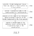
- FIG. 7 is a schematic flowchart illustrating an optical touch control method in accordance with an embodiment of the present invention.
- FIG. 1 is a schematic view of an optical touch system in accordance with an embodiment of the present invention.
- the optical touch system 100 in this embodiment includes a touch surface 110 , light emitting elements 120 - 1 , 120 - 2 and 120 - 3 , image sensing devices 130 - 1 , 130 - 2 , illumination devices 140 - 1 , 140 - 2 and a processing unit 150 .
- the touch surface 110 is configured to have a quadrilateral structure, which is defined by four sequentially-connected edges 110 - 1 , 110 - 2 , 110 - 3 and 110 - 4 thereof.
- the light emitting elements 120 - 1 , 120 - 2 and 120 - 3 are disposed at the edges 110 - 1 , 110 - 2 and 110 - 3 , respectively, and configured to emit light to the touch surface 110 in a first period.
- the light emitting elements 120 - 1 , 120 - 2 and 120 - 3 each can be replaced by a light guide element, which is configured to receive light beams emitted from an external light source and direct the received light beams to illuminate the touch surface 110 .
- the image sensing device 130 - 1 is disposed at an intersecting corner of the edges 110 - 4 , 110 - 1 ; and the image sensing device 130 - 2 is disposed at an intersecting corner of the edges 110 - 4 , 110 - 3 .
- the illumination devices 140 - 1 , 140 - 2 are disposed close to or inside the image sensing devices 130 - 1 , 130 - 2 , respectively.
- the illumination devices 140 - 1 , 140 - 2 are disposed close to the image sensing devices 130 - 1 , 130 - 2 , respectively, and configured to emit light to illuminate the touch surface 110 in a second period.
- the processing unit 150 is electrically connected to the image sensing devices 130 - 1 , 130 - 2 and configured to obtain the two images derived from the image sensing devices 130 - 1 , 130 - 2 sensing the touch surface 110 in the first period and obtain another two images derived from the image sensing devices 130 - 1 , 130 - 2 sensing the touch surface 110 in the second period.
- the processing unit 150 is disposed in either the image sensing device 130 - 1 or the image sensing device 130 - 2 .
- the processing unit 150 is further configured to, when detecting at least one indicator object (e.g., the indicator objects 160 - 1 , 160 - 2 ) closing to the touch surface 110 , determine the actual number of the indicator object and consequently calculate the position of the indicator object(s) relative to the touch surface 110 according to the light-blocking point(s) in the two images captured in the first period and the edge information of the reflective point(s) in the two images captured in the second period.
- at least one indicator object e.g., the indicator objects 160 - 1 , 160 - 2
- the image derived from the image sensing device 130 - 2 sensing the touch surface 110 in the first period has two light-blocking points; but the image derived from the image sensing device 130 - 1 sensing the touch surface 110 in the first period has one light-blocking point only.
- the another two images derived from the image sensing devices 130 - 1 , 130 - 2 respectively sensing the touch surface 110 in the second period both have two reflective points; specifically, it is to be noted that the two reflective points derived from the image sensing device 130 - 1 overlap partially, which leads the overlapping area of the two reflective points has an image edge of one of the two reflective points.
- the processing unit 150 can, according to the aforementioned information contained in the captured images, correctly determine that there are two indicator objects closing to the touch surface 110 and consequently calculate the positions of the two indicator objects relative to the touch surface 110 .
- the processing unit 150 will determine that there are two indicator objects closing to the touch surface 110 if one of the two images, derived from the image sensing devices 130 - 1 , 130 - 2 sensing the touch surface 110 in the first period, has two light-blocking points, the other one of the two image has one light-blocking point only; and the two images, derived from the image sensing devices 130 - 1 , 130 - 2 sensing the touch surface 110 in the second period, both have two reflective points, wherein the two reflective points in one of the image overlap partially, which leads the overlapping area of the two reflective points has an image edge of one of the two reflective points.
- the processing unit 150 will directly determine that there are two indicator objects closing to the touch surface 110 if the two images, derived from the image sensing devices 130 - 1 , 130 - 2 in the first period, both have two distinguishable light-blocking points and the two images, derived from the image sensing devices 130 - 1 , 130 - 2 in the second period, both have two distinguishable reflective points.
- the optical touch system 100 can determine the actual number of the indicator objects on the touch surface 110 while performing the multi-touch operation and consequently calculate the position of the indicator object(s) relative to the touch surface 110 .
- the optical touch system 100 of the present invention can also prevent the number of the indicator object from being determined while performing touch sensing operation in a conventional single-touch optical touch system. The wrong indicator object number determination issue will be described more clear in the following description with a reference of FIGS. 2A , 2 B.
- FIG. 2A is a schematic view illustrating a sensed image of a touch surface of an optical touch system not yet being touched by one single indicator object
- FIG. 2B is a schematic view illustrating a sensed image of a touch surface of an optical touch system being touched by one single indicator object.
- the area 202 is referred to as a bright background formed by a light emitting device of the optical touch system
- the area 204 is referred to as a light-blocking point resulted by the indicator object.
- the bright background 202 in FIG. 2B is constituted by three discontinuous segments 202 - 1 , 202 - 2 and 202 - 3 .
- the touch surface as illustrated in FIG. 2B has a deformation (i.e., a bulge segment 202 - 2 ), which is caused by the pressure resulted by the indicator object pressing the touch surface.
- the touch surface may also have a deformation caused by the gravity, when the touch surface is held by a user at one edge thereof Therefore, the conventional optical touch system may incorrectly determine that there are two indicator objects on the touch surface based on the number of the light-blocking point in the bright background 202 as illustrated in FIG. 2B .
- the optical touch system 100 of the present invention can prevent the aforementioned wrong indicator object number determination issue from occurring. Please refer back to FIG. 1 .
- the two images, respectively captured by the image sensing devices 130 - 1 , 130 - 2 in the first period both have one light-blocking point only and the two images, respectively captured by the image sensing devices 130 - 1 , 130 - 2 in the second period, both have one reflective point only.
- the processing unit 150 accordingly determines that there is one indicator object closing to the touch surface 110 .
- the two images, respectively captured by the image sensing devices 130 - 1 , 130 - 2 in the first period both may have at least two light-blocking points and the two images, respectively captured by the image sensing devices 130 - 1 , 130 - 2 in the second period, both have one reflective point only.
- the processing unit 150 accordingly determines that there is one indicator object touching the touch surface 110 .
- the processing unit 150 is further electrically connected to the three light emitting elements 120 - 1 , 120 - 2 and 120 - 3 and the two illumination devices 140 - 1 , 140 - 2 , and thereby capable of controlling the light emitting elements 120 - 1 , 120 - 2 and 120 - 3 to be turned-on and the illumination devices 140 - 1 , 140 - 2 to be turned-off in the first period and controlling the light emitting elements 120 - 1 , 120 - 2 and 120 - 3 to be turned-off and the illumination devices 140 - 1 , 140 - 2 to be turned-on in the second period.
- the illumination devices 140 - 1 , 140 - 2 both can be realized by an infrared illumination device or a laser emitting device.
- the image sensing devices 130 - 1 , 130 - 2 both are required to employ an infrared filter device, through which only the infrared light can pass, if each one of the illumination devices 140 - 1 , 140 - 2 is realized by an infrared illumination device; wherein the image sensing devices 130 - 1 , 130 - 2 both are configured to capture the image of the touch surface 110 through the employed infrared filter devices.
- the optical touch system 100 shown in FIG. 1 can be summarized to have some basic operation steps by those ordinarily skilled in the art as illustrated in FIG. 3 , which is a schematic flowchart illustrating an operation method of an optical touch system in accordance with an embodiment of the present invention.
- the optical touch system associated with this embodiment includes a touch surface, three light emitting elements, two image sensing devices and two illumination devices.
- the touch surface is configured to have a quadrilateral structure, which is defined by four sequentially-connected first, second, third and fourth edges thereof
- the three light emitting elements are disposed at the first, second and third edges, respectively, and configured to emit light to the touch surface in a first period.
- the two image sensing devices are disposed at an intersecting corner of the fourth and first edges and an intersecting corner of the fourth and third edges, respectively.
- the two illumination devices are disposed close to or inside the two image sensing devices, respectively, and configured to emit light to illuminate the touch surface in a second period.
- the operation method of an optical touch system in this embodiment includes steps of: configuring the two image sensing devices to sense the touch surface in the first period and thereby obtaining a first image and a second image, respectively (step S 302 ); configuring the two image sensing devices to sense the touch surface in a second period and thereby obtaining a third image and a fourth image, respectively (step S 304 ); determining, when at least one indicator object closing to the touch surface is detected, the actual number of the indicator object and further calculating the position of the indicator object(s) relative to the touch surface according to the light-blocking point(s) in the first and second images and the edge information of the reflective point(s) in the third and fourth images (step S 306 ).
- FIG. 4 is a schematic view of an optical touch system in accordance with another embodiment of the present invention.
- the optical touch system 400 in this embodiment includes a touch surface 410 , light emitting elements 420 - 1 , 420 - 2 , a reflective element 425 , image sensing devices 430 - 1 , 430 - 2 , illumination devices 440 - 1 , 440 - 2 and a processing unit 450 .
- the touch surface 410 is configured to have a quadrilateral structure, which is defined by four sequentially-connected edges 410 - 1 , 410 - 2 , 410 - 3 and 410 - 4 thereof.
- the light emitting elements 420 - 1 , 420 - 2 are disposed at the edges 410 - 1 , 410 - 3 , respectively, and configured to emit light to the touch surface 410 in a first period.
- the reflective element 425 is disposed at the edge 410 - 2 .
- the reflective element 425 is realized by a mirror.
- the part below the dotted line 470 in FIG. 4 is a virtual image of the touch surface 410 formed by the reflective element 425 .
- the image sensing device 430 - 1 is disposed at an intersecting corner of the edges 410 - 4 , 410 - 1 ; and the image sensing device 430 - 2 is disposed at an intersecting corner of the edges 410 - 4 , 410 - 3 .
- the illumination devices 440 - 1 , 440 - 2 are disposed close to or inside the image sensing devices 430 - 1 , 430 - 2 , respectively.
- the illumination devices 440 - 1 , 440 - 2 are disposed close to the image sensing devices 430 - 1 , 430 - 2 , respectively, and configured to emit light to illuminate the touch surface 410 in a second period.
- the processing unit 450 is electrically connected to the image sensing devices 430 - 1 , 430 - 2 and configured to obtain the two images derived from the image sensing devices 430 - 1 , 430 - 2 sensing the touch surface 410 in the first period and obtain another two images derived from the image sensing devices 430 - 1 , 430 - 2 sensing the touch surface 410 in the second period.
- the processing unit 450 is further configured to, when detecting at least one indicator object (e.g., the indicator objects 460 - 1 , 460 - 2 ) closing to the touch surface 410 , determine that which indicator object(s) (e.g., the indicator objects 460 - 3 , 460 - 4 ) in the two images captured in the first period is derived from the mirror image formed by the reflective element 425 according to the relative position of the reflective point(s) in the two images captured in the second period.
- at least one indicator object e.g., the indicator objects 460 - 1 , 460 - 2
- the two indicator objects 460 - 1 , 460 - 2 with specific relative positions as illustrated in FIG. 4 as an example.
- the two image respectively derived from the image sensing device 430 - 1 , 430 - 2 sensing the touch surface 410 in the first period both have four light-blocking points, and the four light-blocking points each are referred to as an image of a real indicator object by the processing unit 450 at this time.
- the two images respectively derived from the image sensing device 430 - 1 , 430 - 2 sensing the touch surface 410 in the second period both have two light-blocking point only, due to the vertical indicator objects 460 - 3 , 460 - 4 do not reflect light.
- the processing unit 450 can determine that which indicator objects (e.g., the indicator objects 460 - 3 , 460 - 4 ) in the two images captured in the first period are derived from the mirror image formed by the reflective element 425 according to the relative positions of the two light-blocking points in the two images captured in the second period. Consequently, the processing unit 450 is further configured to calculate the position of the indicator object relative to the touch surface 410 according to the image of real indicator object and the image of vertical indicator object.
- indicator objects e.g., the indicator objects 460 - 3 , 460 - 4
- the processing unit 450 is further electrically connected to the two light emitting elements 420 - 1 , 420 - 2 and the two illumination devices 440 - 1 , 440 - 2 , and thereby capable of controlling the light emitting elements 420 - 1 , 420 - 2 to be turned-on and the illumination devices 440 - 1 , 440 - 2 to be turned-off in the first period and controlling the light emitting elements 420 - 1 , 420 - 2 to be turned-off and the illumination devices 140 - 1 , 140 - 2 to be turned-on in the second period.
- the illumination devices 440 - 1 , 440 - 2 both can be realized by an infrared illumination device or a laser emitting device.
- the image sensing devices 430 - 1 , 430 - 2 both are required to employ an infrared filter device, through which only the infrared light can pass, if each one of the illumination devices 440 - 1 , 440 - 2 is realized by an infrared illumination device; wherein, the image sensing devices 430 - 1 , 430 - 2 are configured to capture the image of the touch surface 410 through the employed infrared filter devices.
- the optical touch system 400 shown in FIG. 4 can be summarized to have some basic operation steps by those ordinarily skilled in the art as illustrated in FIG. 5 , which is a schematic flowchart illustrating an operation method of an optical touch system in accordance with another embodiment of the present invention.
- the optical touch system associated with this embodiment includes a touch surface, two light emitting elements, a reflective element, two image sensing devices and two illumination devices.
- the touch surface is configured to have a quadrilateral structure, which is defined by four sequentially-connected first, second, third and fourth edges thereof
- the two light emitting elements are disposed at the first and third edges, respectively, and are configured to emit light to the touch surface in a first period.
- the reflective element is disposed at the second edge of the touch surface.
- the two image sensing devices are disposed at an intersecting corner of the fourth and first edges and an intersecting corner of the fourth and third edges, respectively.
- the two illumination devices are disposed close to or inside the two image sensing devices, respectively, and are configured to emit light to illuminate the touch surface in a second period.
- the operation method of an optical touch system in this embodiment includes steps of: configuring the two image sensing devices to sense the touch surface in the first period and thereby obtaining a first image and a second image, respectively (step S 502 ); configuring the two image sensing devices to sense the touch surface in the second period and thereby obtaining a third image and a fourth image, respectively (step S 504 ); determining, when at least one indicator object closing to the touch surface is detected, that which indicator object image(s) in the first and second images is derived from the mirror image formed by the reflective element according to the relative position of the light-blocking point(s) in the third and fourth images (step S 506 ).
- FIG. 6 is a schematic view of an optical touch system in accordance with still another embodiment of the present invention.
- the optical touch system 600 in this embodiment includes a touch surface 610 , an image sensing device 620 , a background light emitting element 630 and an illumination device 640 .
- the background light emitting element 630 is configured to emit light to illuminate the touch surface 610 from at least one edge thereof in a first period so as to generate a bright background for the image captured by the image sensing device 620 .
- the illumination device 640 is configured to provide illumination light to the touch surface 610 in a second period.
- the image sensing device 620 in the first period, is configured to capture the image of an indicator object 660 blocking a portion of the bright background; and the image sensing device 620 , in the second period, is configured to capture the image of the indicator object 660 reflecting the illumination light.
- the background light emitting element 630 can be realized by three light guide modules 630 - 1 , 630 - 2 and 630 - 3 , which are disposed at the three edges of the touch surface 610 , respectively.
- the light guide module 630 - 2 can be replaced by a reflective element in another embodiment.
- the background light emitting element 630 may include a light guide module(s), disposed at one or more edges of the touch surface 610 , and a reflective element(s), disposed at another one or more edge of the touch surface 610 .
- the optical touch system 600 may include more than one image sensing devices 620 ; but the present invention is not limited thereto.
- FIG. 7 is a schematic flowchart illustrating an optical touch control method in accordance with an embodiment of the present invention. As illustrated in FIG. 7 ,
- the optical touch control method in this embodiment includes steps of: providing a bright background from at least one edge of a touch surface in a first period (step S 702 ); providing illumination light to the touch surface in a second period (step S 704 ); capturing a first image of an indicator object blocking a portion of the bright background in the first period (step S 706 ); and capturing a second image of the indicator object reflecting the illumination light in the second period (step S 708 ).
- the optical touch system includes at least one light emitting element, at least one illumination device and at least one image sensing device.
- the light emitting element is disposed at an edge(s) of a touch surface of the optical touch system and configured to emit light to the touch surface in a first period and thereby generating a bright background for the image captured by the image sensing device.
- the illumination device is configured to provide illumination light to the touch surface in a second period so that an indicator object on the touch surface can reflect the illumination light.
- the image sensing device is configured sensing the touch surface and thereby obtaining two images in the first and second periods.
- the optical touch system can correctly determine the actual number of the indicator object and consequently calculate the positions of the indicator objects relative to the touch surface according to the aforementioned light-blocking points and the edge information of the reflective points while performing the multi-touch operation.
Landscapes
- Engineering & Computer Science (AREA)
- General Engineering & Computer Science (AREA)
- Theoretical Computer Science (AREA)
- Human Computer Interaction (AREA)
- Physics & Mathematics (AREA)
- General Physics & Mathematics (AREA)
- Position Input By Displaying (AREA)
Applications Claiming Priority (2)
| Application Number | Priority Date | Filing Date | Title |
|---|---|---|---|
| TW101128949A TWI464653B (zh) | 2012-08-10 | 2012-08-10 | 光學觸控系統與光學觸控方法 |
| TW101128949 | 2012-08-10 |
Publications (2)
| Publication Number | Publication Date |
|---|---|
| US20140043297A1 US20140043297A1 (en) | 2014-02-13 |
| US9207809B2 true US9207809B2 (en) | 2015-12-08 |
Family
ID=50065849
Family Applications (1)
| Application Number | Title | Priority Date | Filing Date |
|---|---|---|---|
| US13/856,432 Expired - Fee Related US9207809B2 (en) | 2012-08-10 | 2013-04-03 | Optical touch system and optical touch control method |
Country Status (2)
| Country | Link |
|---|---|
| US (1) | US9207809B2 (zh) |
| TW (1) | TWI464653B (zh) |
Families Citing this family (2)
| Publication number | Priority date | Publication date | Assignee | Title |
|---|---|---|---|---|
| TWI525510B (zh) * | 2014-08-01 | 2016-03-11 | 緯創資通股份有限公司 | 光學觸控系統及光學觸控方法 |
| WO2022222981A1 (zh) * | 2021-04-22 | 2022-10-27 | 广州创知科技有限公司 | 一种触控校验方法、装置、交互平板和存储介质 |
Citations (9)
| Publication number | Priority date | Publication date | Assignee | Title |
|---|---|---|---|---|
| US20100295821A1 (en) * | 2009-05-20 | 2010-11-25 | Tom Chang | Optical touch panel |
| CN101907956A (zh) | 2010-08-13 | 2010-12-08 | 苏州佳世达电通有限公司 | 判断光学触控屏幕被触控位置的方法 |
| CN102043540A (zh) | 2009-10-15 | 2011-05-04 | 原相科技股份有限公司 | 光学触控装置及其光学触控装置的定位方法及线光源模块 |
| CN102043543A (zh) | 2009-10-09 | 2011-05-04 | 宏碁股份有限公司 | 光学式触控系统及其方法 |
| US20110261016A1 (en) * | 2010-04-23 | 2011-10-27 | Sunplus Innovation Technology Inc. | Optical touch screen system and method for recognizing a relative distance of objects |
| CN102364418A (zh) | 2011-09-19 | 2012-02-29 | 广东威创视讯科技股份有限公司 | 一种光学触控定位系统及方法 |
| US20120162136A1 (en) | 2010-12-24 | 2012-06-28 | Lite-On Semiconductor Corp. | Optical touch panel and method of detecting touch point positions on an optical touch panel |
| US8269158B2 (en) * | 2008-10-10 | 2012-09-18 | Pixart Imaging Inc. | Sensing system and method for obtaining position of pointer thereof |
| US8937612B2 (en) * | 2010-02-04 | 2015-01-20 | Hong Kong Applied Science And Technology Research Institute Co. Ltd. | Coordinate locating method, coordinate locating device, and display apparatus comprising the coordinate locating device |
-
2012
- 2012-08-10 TW TW101128949A patent/TWI464653B/zh not_active IP Right Cessation
-
2013
- 2013-04-03 US US13/856,432 patent/US9207809B2/en not_active Expired - Fee Related
Patent Citations (10)
| Publication number | Priority date | Publication date | Assignee | Title |
|---|---|---|---|---|
| US8269158B2 (en) * | 2008-10-10 | 2012-09-18 | Pixart Imaging Inc. | Sensing system and method for obtaining position of pointer thereof |
| US20100295821A1 (en) * | 2009-05-20 | 2010-11-25 | Tom Chang | Optical touch panel |
| CN102043543A (zh) | 2009-10-09 | 2011-05-04 | 宏碁股份有限公司 | 光学式触控系统及其方法 |
| CN102043540A (zh) | 2009-10-15 | 2011-05-04 | 原相科技股份有限公司 | 光学触控装置及其光学触控装置的定位方法及线光源模块 |
| US8937612B2 (en) * | 2010-02-04 | 2015-01-20 | Hong Kong Applied Science And Technology Research Institute Co. Ltd. | Coordinate locating method, coordinate locating device, and display apparatus comprising the coordinate locating device |
| US20110261016A1 (en) * | 2010-04-23 | 2011-10-27 | Sunplus Innovation Technology Inc. | Optical touch screen system and method for recognizing a relative distance of objects |
| CN101907956A (zh) | 2010-08-13 | 2010-12-08 | 苏州佳世达电通有限公司 | 判断光学触控屏幕被触控位置的方法 |
| US20120162136A1 (en) | 2010-12-24 | 2012-06-28 | Lite-On Semiconductor Corp. | Optical touch panel and method of detecting touch point positions on an optical touch panel |
| CN102541356A (zh) | 2010-12-24 | 2012-07-04 | 敦南科技股份有限公司 | 用于光学式触控面板的触碰点定位方法及光学式触控面板装置 |
| CN102364418A (zh) | 2011-09-19 | 2012-02-29 | 广东威创视讯科技股份有限公司 | 一种光学触控定位系统及方法 |
Also Published As
| Publication number | Publication date |
|---|---|
| TWI464653B (zh) | 2014-12-11 |
| TW201407446A (zh) | 2014-02-16 |
| US20140043297A1 (en) | 2014-02-13 |
Similar Documents
| Publication | Publication Date | Title |
|---|---|---|
| US10324566B2 (en) | Enhanced interaction touch system | |
| JP5680976B2 (ja) | 電子黒板システム及びプログラム | |
| KR101033428B1 (ko) | 에어리어 이미지 센서를 사용한 위치 검출 장치 | |
| CN103003778B (zh) | 交互式输入系统和用于其的笔工具 | |
| KR20120058594A (ko) | 향상된 신호 대 노이즈비(snr)를 갖는 인터랙티브 입력 시스템 및 이미지 캡처 방법 | |
| KR20170141522A (ko) | 지문 인식 기능을 지원하는 전자 장치 및 이의 운용 방법 | |
| JP2010257089A (ja) | 光学式位置検出装置 | |
| JP2010277122A (ja) | 光学式位置検出装置 | |
| US20110122099A1 (en) | Multiple-input touch panel and method for gesture recognition | |
| KR20100055516A (ko) | 개선된 조광을 가진 광학 터치 스크린 | |
| US9501160B2 (en) | Coordinate detection system and information processing apparatus | |
| TWI520036B (zh) | 物件偵測方法以及用於光學觸控系統的校正裝置 | |
| JP5852120B2 (ja) | 接触測位方法、及びタッチスクリーン | |
| TW201112092A (en) | Optical touch system and method thereof | |
| EP2524285B1 (en) | Interactive system with successively activated illumination sources | |
| US9471180B2 (en) | Optical touch panel system, optical apparatus and positioning method thereof | |
| TW201128489A (en) | Object-detecting system and method by use of non-coincident fields of light | |
| TWI534687B (zh) | 光學觸控系統及其物件分析方法 | |
| US20110193969A1 (en) | Object-detecting system and method by use of non-coincident fields of light | |
| TW201220147A (en) | Touch device and touch method | |
| CN109726650B (zh) | 显示屏、电子设备及指纹处理方法 | |
| US9207809B2 (en) | Optical touch system and optical touch control method | |
| KR101488287B1 (ko) | 터치 인식 디스플레이 장치 | |
| KR101359731B1 (ko) | 반사부를 이용한 터치인식 시스템 | |
| JP2010282463A (ja) | タッチパネル装置 |
Legal Events
| Date | Code | Title | Description |
|---|---|---|---|
| AS | Assignment |
Owner name: PIXART IMAGING INC., TAIWAN Free format text: ASSIGNMENT OF ASSIGNORS INTEREST;ASSIGNORS:SU, TZUNG-MIN;LIAO, CHI-CHIEH;CHENG, HAN-PING;AND OTHERS;REEL/FRAME:030147/0039 Effective date: 20130314 |
|
| STCF | Information on status: patent grant |
Free format text: PATENTED CASE |
|
| FEPP | Fee payment procedure |
Free format text: ENTITY STATUS SET TO UNDISCOUNTED (ORIGINAL EVENT CODE: BIG.); ENTITY STATUS OF PATENT OWNER: LARGE ENTITY |
|
| MAFP | Maintenance fee payment |
Free format text: PAYMENT OF MAINTENANCE FEE, 4TH YEAR, LARGE ENTITY (ORIGINAL EVENT CODE: M1551); ENTITY STATUS OF PATENT OWNER: LARGE ENTITY Year of fee payment: 4 |
|
| FEPP | Fee payment procedure |
Free format text: MAINTENANCE FEE REMINDER MAILED (ORIGINAL EVENT CODE: REM.); ENTITY STATUS OF PATENT OWNER: LARGE ENTITY |
|
| LAPS | Lapse for failure to pay maintenance fees |
Free format text: PATENT EXPIRED FOR FAILURE TO PAY MAINTENANCE FEES (ORIGINAL EVENT CODE: EXP.); ENTITY STATUS OF PATENT OWNER: LARGE ENTITY |
|
| STCH | Information on status: patent discontinuation |
Free format text: PATENT EXPIRED DUE TO NONPAYMENT OF MAINTENANCE FEES UNDER 37 CFR 1.362 |
|
| FP | Lapsed due to failure to pay maintenance fee |
Effective date: 20231208 |