US9198670B2 - Filamentary devices for treatment of vascular defects - Google Patents
Filamentary devices for treatment of vascular defects Download PDFInfo
- Publication number
- US9198670B2 US9198670B2 US14/743,627 US201514743627A US9198670B2 US 9198670 B2 US9198670 B2 US 9198670B2 US 201514743627 A US201514743627 A US 201514743627A US 9198670 B2 US9198670 B2 US 9198670B2
- Authority
- US
- United States
- Prior art keywords
- filaments
- permeable shell
- elongate
- cross sectional
- sectional area
- Prior art date
- Legal status (The legal status is an assumption and is not a legal conclusion. Google has not performed a legal analysis and makes no representation as to the accuracy of the status listed.)
- Active
Links
Images


Classifications
-
- A—HUMAN NECESSITIES
- A61—MEDICAL OR VETERINARY SCIENCE; HYGIENE
- A61B—DIAGNOSIS; SURGERY; IDENTIFICATION
- A61B17/00—Surgical instruments, devices or methods, e.g. tourniquets
- A61B17/12—Surgical instruments, devices or methods, e.g. tourniquets for ligaturing or otherwise compressing tubular parts of the body, e.g. blood vessels, umbilical cord
- A61B17/12022—Occluding by internal devices, e.g. balloons or releasable wires
- A61B17/12099—Occluding by internal devices, e.g. balloons or releasable wires characterised by the location of the occluder
- A61B17/12109—Occluding by internal devices, e.g. balloons or releasable wires characterised by the location of the occluder in a blood vessel
- A61B17/12113—Occluding by internal devices, e.g. balloons or releasable wires characterised by the location of the occluder in a blood vessel within an aneurysm
-
- A—HUMAN NECESSITIES
- A61—MEDICAL OR VETERINARY SCIENCE; HYGIENE
- A61B—DIAGNOSIS; SURGERY; IDENTIFICATION
- A61B17/00—Surgical instruments, devices or methods, e.g. tourniquets
- A61B17/12—Surgical instruments, devices or methods, e.g. tourniquets for ligaturing or otherwise compressing tubular parts of the body, e.g. blood vessels, umbilical cord
- A61B17/12009—Implements for ligaturing other than by clamps or clips, e.g. using a loop with a slip knot
- A61B17/12013—Implements for ligaturing other than by clamps or clips, e.g. using a loop with a slip knot for use in minimally invasive surgery, e.g. endoscopic surgery
-
- A—HUMAN NECESSITIES
- A61—MEDICAL OR VETERINARY SCIENCE; HYGIENE
- A61B—DIAGNOSIS; SURGERY; IDENTIFICATION
- A61B17/00—Surgical instruments, devices or methods, e.g. tourniquets
- A61B17/12—Surgical instruments, devices or methods, e.g. tourniquets for ligaturing or otherwise compressing tubular parts of the body, e.g. blood vessels, umbilical cord
- A61B17/12022—Occluding by internal devices, e.g. balloons or releasable wires
- A61B17/12027—Type of occlusion
- A61B17/12031—Type of occlusion complete occlusion
-
- A—HUMAN NECESSITIES
- A61—MEDICAL OR VETERINARY SCIENCE; HYGIENE
- A61B—DIAGNOSIS; SURGERY; IDENTIFICATION
- A61B17/00—Surgical instruments, devices or methods, e.g. tourniquets
- A61B17/12—Surgical instruments, devices or methods, e.g. tourniquets for ligaturing or otherwise compressing tubular parts of the body, e.g. blood vessels, umbilical cord
- A61B17/12022—Occluding by internal devices, e.g. balloons or releasable wires
- A61B17/12099—Occluding by internal devices, e.g. balloons or releasable wires characterised by the location of the occluder
- A61B17/12109—Occluding by internal devices, e.g. balloons or releasable wires characterised by the location of the occluder in a blood vessel
- A61B17/12113—Occluding by internal devices, e.g. balloons or releasable wires characterised by the location of the occluder in a blood vessel within an aneurysm
- A61B17/12118—Occluding by internal devices, e.g. balloons or releasable wires characterised by the location of the occluder in a blood vessel within an aneurysm for positioning in conjunction with a stent
-
- A—HUMAN NECESSITIES
- A61—MEDICAL OR VETERINARY SCIENCE; HYGIENE
- A61B—DIAGNOSIS; SURGERY; IDENTIFICATION
- A61B17/00—Surgical instruments, devices or methods, e.g. tourniquets
- A61B17/12—Surgical instruments, devices or methods, e.g. tourniquets for ligaturing or otherwise compressing tubular parts of the body, e.g. blood vessels, umbilical cord
- A61B17/12022—Occluding by internal devices, e.g. balloons or releasable wires
- A61B17/12131—Occluding by internal devices, e.g. balloons or releasable wires characterised by the type of occluding device
- A61B17/12168—Occluding by internal devices, e.g. balloons or releasable wires characterised by the type of occluding device having a mesh structure
- A61B17/12172—Occluding by internal devices, e.g. balloons or releasable wires characterised by the type of occluding device having a mesh structure having a pre-set deployed three-dimensional shape
-
- A—HUMAN NECESSITIES
- A61—MEDICAL OR VETERINARY SCIENCE; HYGIENE
- A61B—DIAGNOSIS; SURGERY; IDENTIFICATION
- A61B17/00—Surgical instruments, devices or methods, e.g. tourniquets
- A61B17/12—Surgical instruments, devices or methods, e.g. tourniquets for ligaturing or otherwise compressing tubular parts of the body, e.g. blood vessels, umbilical cord
- A61B17/12022—Occluding by internal devices, e.g. balloons or releasable wires
- A61B17/12131—Occluding by internal devices, e.g. balloons or releasable wires characterised by the type of occluding device
- A61B17/12168—Occluding by internal devices, e.g. balloons or releasable wires characterised by the type of occluding device having a mesh structure
- A61B17/12177—Occluding by internal devices, e.g. balloons or releasable wires characterised by the type of occluding device having a mesh structure comprising additional materials, e.g. thrombogenic, having filaments, having fibers or being coated
-
- A—HUMAN NECESSITIES
- A61—MEDICAL OR VETERINARY SCIENCE; HYGIENE
- A61B—DIAGNOSIS; SURGERY; IDENTIFICATION
- A61B17/00—Surgical instruments, devices or methods, e.g. tourniquets
- A61B2017/00535—Surgical instruments, devices or methods, e.g. tourniquets pneumatically or hydraulically operated
- A61B2017/00539—Surgical instruments, devices or methods, e.g. tourniquets pneumatically or hydraulically operated hydraulically
-
- A—HUMAN NECESSITIES
- A61—MEDICAL OR VETERINARY SCIENCE; HYGIENE
- A61B—DIAGNOSIS; SURGERY; IDENTIFICATION
- A61B17/00—Surgical instruments, devices or methods, e.g. tourniquets
- A61B2017/00743—Type of operation; Specification of treatment sites
- A61B2017/00778—Operations on blood vessels
-
- A—HUMAN NECESSITIES
- A61—MEDICAL OR VETERINARY SCIENCE; HYGIENE
- A61B—DIAGNOSIS; SURGERY; IDENTIFICATION
- A61B17/00—Surgical instruments, devices or methods, e.g. tourniquets
- A61B2017/00831—Material properties
- A61B2017/00867—Material properties shape memory effect
-
- A—HUMAN NECESSITIES
- A61—MEDICAL OR VETERINARY SCIENCE; HYGIENE
- A61B—DIAGNOSIS; SURGERY; IDENTIFICATION
- A61B17/00—Surgical instruments, devices or methods, e.g. tourniquets
- A61B17/12—Surgical instruments, devices or methods, e.g. tourniquets for ligaturing or otherwise compressing tubular parts of the body, e.g. blood vessels, umbilical cord
- A61B17/12022—Occluding by internal devices, e.g. balloons or releasable wires
- A61B2017/1205—Introduction devices
- A61B2017/12054—Details concerning the detachment of the occluding device from the introduction device
- A61B2017/12068—Details concerning the detachment of the occluding device from the introduction device detachable by heat
-
- A—HUMAN NECESSITIES
- A61—MEDICAL OR VETERINARY SCIENCE; HYGIENE
- A61B—DIAGNOSIS; SURGERY; IDENTIFICATION
- A61B17/00—Surgical instruments, devices or methods, e.g. tourniquets
- A61B17/12—Surgical instruments, devices or methods, e.g. tourniquets for ligaturing or otherwise compressing tubular parts of the body, e.g. blood vessels, umbilical cord
- A61B17/12022—Occluding by internal devices, e.g. balloons or releasable wires
- A61B2017/1205—Introduction devices
- A61B2017/12054—Details concerning the detachment of the occluding device from the introduction device
- A61B2017/1209—Details concerning the detachment of the occluding device from the introduction device detachable by electrical current or potential, e.g. electroactive polymer
-
- A—HUMAN NECESSITIES
- A61—MEDICAL OR VETERINARY SCIENCE; HYGIENE
- A61B—DIAGNOSIS; SURGERY; IDENTIFICATION
- A61B17/00—Surgical instruments, devices or methods, e.g. tourniquets
- A61B17/12—Surgical instruments, devices or methods, e.g. tourniquets for ligaturing or otherwise compressing tubular parts of the body, e.g. blood vessels, umbilical cord
- A61B17/12022—Occluding by internal devices, e.g. balloons or releasable wires
- A61B2017/1205—Introduction devices
- A61B2017/12054—Details concerning the detachment of the occluding device from the introduction device
- A61B2017/12095—Threaded connection
-
- A—HUMAN NECESSITIES
- A61—MEDICAL OR VETERINARY SCIENCE; HYGIENE
- A61B—DIAGNOSIS; SURGERY; IDENTIFICATION
- A61B90/00—Instruments, implements or accessories specially adapted for surgery or diagnosis and not covered by any of the groups A61B1/00 - A61B50/00, e.g. for luxation treatment or for protecting wound edges
- A61B90/39—Markers, e.g. radio-opaque or breast lesions markers
- A61B2090/3966—Radiopaque markers visible in an X-ray image
Definitions
- Embodiments of devices and methods herein are directed to blocking a flow of fluid through a tubular vessel or into a small interior chamber of a saccular cavity or vascular defect within a mammalian body. More specifically, embodiments herein are directed to devices and methods for treatment of a vascular defect of a patient including some embodiments directed specifically to the treatment of cerebral aneurysms of patients.
- the mammalian circulatory system is comprised of a heart, which acts as a pump, and a system of blood vessels which transport the blood to various points in the body. Due to the force exerted by the flowing blood on the blood vessel the blood vessels may develop a variety of vascular defects.
- vascular aneurysm results from the abnormal widening of the blood vessel.
- vascular aneurysms are formed as a result of the weakening of the wall of a blood vessel and subsequent ballooning and expansion of the vessel wall. If, for example, an aneurysm is present within an artery of the brain, and the aneurysm should burst with resulting cranial hemorrhaging, death could occur.
- Surgical techniques for the treatment of cerebral aneurysms typically involve a craniotomy requiring creation of an opening in the skull of the patient through which the surgeon can insert instruments to operate directly on the patient's brain.
- the brain must be retracted to expose the parent blood vessel from which the aneurysm arises.
- the surgeon places a clip across the neck of the aneurysm thereby preventing arterial blood from entering the aneurysm.
- Surgical techniques may be effective treatment for many aneurysms.
- surgical techniques for treating these types of conditions include major invasive surgical procedures which often require extended periods of time under anesthesia involving high risk to the patient. Such procedures thus require that the patient be in generally good physical condition in order to be a candidate for such procedures.
- vaso-occlusion devices may be placed within the vasculature of the human body, typically via a catheter, either to block the flow of blood through a vessel with an aneurysm through the formation of an embolus or to form such an embolus within an aneurysm stemming from the vessel.
- a variety of implantable, coil-type vaso-occlusion devices are known.
- the coils of such devices may themselves be formed into a secondary coil shape, or any of a variety of more complex secondary shapes.
- Vaso-occlusive coils are commonly used to treat cerebral aneurysms but suffer from several limitations including poor packing density, compaction due to hydrodynamic pressure from blood flow, poor stability in wide-necked aneurysms and complexity and difficulty in the deployment thereof as most aneurysm treatments with this approach require the deployment of multiple coils.
- Another approach to treating aneurysms without the need for invasive surgery involves the placement of sleeves or stents into the vessel and across the region where the aneurysm occurs. Such devices maintain blood flow through the vessel while reducing blood pressure applied to the interior of the aneurysm.
- Certain types of stents are expanded to the proper size by inflating a balloon catheter, referred to as balloon expandable stents, while other stents are designed to elastically expand in a self-expanding manner.
- Some stents are covered typically with a sleeve of polymeric material called a graft to form a stent-graft.
- Stents and stent-grafts are generally delivered to a preselected position adjacent a vascular defect through a delivery catheter.
- covered stents or stent-grafts have seen very limited use due to the likelihood of inadvertent occlusion of small perforator vessels that may be near the vascular defect being treated.
- stents are generally not sufficient as a stand-alone treatment.
- their density is usually reduced such that when expanded there is only a small amount of stent structure bridging the aneurysm neck.
- vaso-occlusive devices such as the coils discussed above, to achieve aneurysm occlusion.
- aneurysm neck bridging devices with defect spanning portions or regions have been attempted, however, none of these devices have had a significant measure of clinical success or usage.
- a major limitation in their adoption and clinical usefulness is the inability to position the defect spanning portion to assure coverage of the neck.
- Existing stent delivery systems that are neurovascular compatible i.e., deliverable through a microcatheter and highly flexible
- Another limitation of many aneurysm bridging devices described in the prior art is the poor flexibility. Cerebral blood vessels are tortuous and a high degree of flexibility is required for effective delivery to most aneurysm locations in the brain.
- One embodiment of a device for treatment of a patient's vasculature includes a self-expanding resilient permeable shell having a radially constrained elongated state configured for delivery within a catheter lumen, an expanded state with a globular and longitudinally shortened configuration relative to the radially constrained state, and a plurality of elongate filaments which are woven together, which define a cavity of the permeable shell and which include at least about 40% composite filaments relative to a total number of filaments, the composite filaments including a high strength material and a highly radiopaque material.
- a device for treatment of a patient's vasculature includes a self-expanding resilient permeable shell having a radially constrained elongated state configured for delivery within a catheter lumen, an expanded state with a globular and longitudinally shortened configuration relative to the radially constrained state, and a plurality of elongate filaments which are woven together, the plurality of filaments having a total cross sectional area and further defining a cavity of the permeable shell and which include at least some composite filaments, the composite filaments including a high strength material and a highly radiopaque material, and wherein the total cross sectional area of the highly radiopaque material is between about 11% and about 30% of the total cross sectional area of the plurality of elongate filaments.
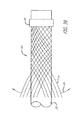
- FIG. 1 is an elevation view of an embodiment of a device for treatment of a patient's vasculature and a plurality of arrows indicating inward radial force.
- FIG. 2 is an elevation view of a beam supported by two simple supports and a plurality of arrows indicating force against the beam.
- FIG. 3 is a bottom perspective view of an embodiment of a device for treatment of a patient's vasculature.
- FIG. 4 is an elevation view of the device for treatment of a patient's vasculature of FIG. 3 .
- FIG. 5 is a transverse cross sectional view of the device of FIG. 4 taken along lines 5 - 5 in FIG. 4 .
- FIG. 6 shows the device of FIG. 4 in longitudinal section taken along lines 6 - 6 in FIG. 4 .
- FIG. 7 is an enlarged view of the woven filament structure taken from the encircled portion 7 shown in FIG. 5 .
- FIG. 8 is an enlarged view of the woven filament structure taken from the encircled portion 8 shown in FIG. 6 .
- FIG. 9 is a proximal end view of the device of FIG. 3 .
- FIG. 10 is a transverse sectional view of a proximal hub portion of the device in FIG. 6 indicated by lines 10 - 10 in FIG. 6 .
- FIG. 11 is an elevation view in partial section of a distal end of a delivery catheter with the device for treatment of a patient's vasculature of FIG. 3 disposed therein in a collapsed constrained state.
- FIG. 12 is an elevation view of a distal portion of a delivery device or actuator showing some internal structure of the device.
- FIG. 13 is an elevation view of the delivery device of FIG. 12 with the addition of some tubular elements over the internal structures.
- FIG. 14 is an elevation view of the distal portion of the delivery device of FIG. 13 with an outer coil and marker in place.
- FIG. 15 is an elevation view of a proximal portion of the delivery device.
- FIG. 16 illustrates an embodiment of a filament configuration for a device for treatment of a patient's vasculature.
- FIG. 17 is a schematic view of a patient being accessed by an introducer sheath, a microcatheter and a device for treatment of a patient's vasculature releasably secured to a distal end of a delivery device or actuator.
- FIG. 18 is a sectional view of a terminal aneurysm.
- FIG. 19 is a sectional view of an aneurysm.
- FIG. 20 is a schematic view in section of an aneurysm showing perpendicular arrows which indicate interior nominal longitudinal and transverse dimensions of the aneurysm.
- FIG. 21 is a schematic view in section of the aneurysm of FIG. 20 with a dashed outline of a device for treatment of a patient's vasculature in a relaxed unconstrained state that extends transversely outside of the walls of the aneurysm.
- FIG. 22 is a schematic view in section of an outline of a device represented by the dashed line in FIG. 21 in a deployed and partially constrained state within the aneurysm.
- FIGS. 23-26 show a deployment sequence of a device for treatment of a patient's vasculature.
- FIG. 27 is an elevation view in partial section of an embodiment of a device for treatment of a patient's vasculature deployed within an aneurysm at a tilted angle.
- FIG. 28 is an elevation view in partial section of an embodiment of a device for treatment of a patient's vasculature deployed within an irregularly shaped aneurysm.
- FIG. 29 shows an elevation view in section of a device for treatment of a patient's vasculature deployed within a vascular defect aneurysm.
- FIG. 30 shows a proximal perspective view of an embodiment of a device for treatment of a patient's vasculature with a sealing zone embodiment indicated by a set of dashed lines.
- FIGS. 31-35 illustrate various different embodiments of braiding patterns that may be used for permeable shells of devices for treatment of a patient's vasculature.
- FIG. 36 illustrates a device for treatment of a patient's vasculature that includes non-structural fibers in the permeable shell structure of the device.
- FIG. 37 is an enlarged view of non-structural fibers woven into filaments of a permeable shell structure.
- FIG. 38 is an elevation view of a mandrel used for manufacture of a braided tubular member for construction of an embodiment of a device for treatment of a patient's vasculature with the initiation of the braiding process shown.
- FIG. 39 is an elevation view of a braiding process for a braided tubular member used for manufacture of a device.
- FIG. 40 is an elevation view in partial section of an embodiment of a fixture for heat setting a braided tubular member for manufacture of a device for treatment of a patient's vasculature.
- FIG. 41 is an elevation view in partial section of an embodiment of a fixture for heat setting a braided tubular member for manufacture of a device for treatment of a patient's vasculature.
- FIG. 42 is an elevation view in section that illustrates a flow of blood within an aneurysm of a patient's vasculature.
- FIG. 43 is an elevation view in partial section of an embodiment of a device for treatment of a patient's vasculature.
- FIG. 44 is an elevation view in partial section of an embodiment of a device for treatment of a patient's vasculature.
- FIG. 45 is an elevation view of an embodiment of a device for treatment of a patient's vasculature.
- FIG. 46 is an elevation view in partial section of an embodiment of a device for treatment of a patient's vasculature.
- FIG. 47 represents the image of an angiogram depicting an aneurysm prior to treatment.
- FIG. 48 is depicts the aneurysm of FIG. 47 ten (10) minutes post-treatment.
- FIG. 49 is a perspective view in section of a of a composite filament embodiment.
- FIG. 50 is an elevation view of an embodiment of a device for treatment of a patient's vasculature.
- FIG. 51 is a perspective view of an embodiment of a mandrel for making the embodiment of FIG. 50 .
- FIG. 52 is a top view of the mandrel of FIG. 51 with filaments loaded for braiding.
- some device embodiments may be configured for collapse to a low profile constrained state with a transverse dimension suitable for delivery through an inner lumen of a microcatheter and deployment from a distal end thereof.
- Embodiments of these devices may also maintain a clinically effective configuration with sufficient mechanical integrity once deployed so as to withstand dynamic forces within a patient's vasculature over time that may otherwise result in compaction of a deployed device. It may also be desirable for some device embodiments to acutely occlude a vascular defect of a patient during the course of a procedure in order to provide more immediate feedback regarding success of the treatment to a treating physician.
- Some embodiments are particularly useful for the treatment of cerebral aneurysms by reconstructing a vascular wall so as to wholly or partially isolate a vascular defect from a patient's blood flow.
- Some embodiments may be configured to be deployed within a vascular defect to facilitate reconstruction, bridging of a vessel wall or both in order to treat the vascular defect.
- a permeable shell of the device may be configured to anchor or fix the permeable shell in a clinically beneficial position.
- the device may be disposed in whole or in part within the vascular defect in order to anchor or fix the device with respect to the vascular structure or defect.
- the permeable shell may be configured to span an opening, neck or other portion of a vascular defect in order to isolate the vascular defect, or a portion thereof, from the patient's nominal vascular system in order allow the defect to heal or to otherwise minimize the risk of the defect to the patient's health.
- the permeable shell may be configured to allow some initial perfusion of blood through the permeable shell.
- the porosity of the permeable shell may be configured to sufficiently isolate the vascular defect so as to promote healing and isolation of the defect, but allow sufficient initial flow through the permeable shell so as to reduce or otherwise minimize the mechanical force exerted on the membrane the dynamic flow of blood or other fluids within the vasculature against the device.
- a portion of the permeable shell that spans the opening or neck of the vascular defect need be permeable and/or conducive to thrombus formation in a patient's bloodstream.
- that portion of the device that does not span an opening or neck of the vascular defect may be substantially non-permeable or completely permeable with a pore or opening configuration that is too large to effectively promote thrombus formation.
- a hollow, thin walled device with a permeable shell of resilient material that may be constrained to a low profile for delivery within a patient.
- a device may also be configured to expand radially outward upon removal of the constraint such that the shell of the device assumes a larger volume and fills or otherwise occludes a vascular defect within which it is deployed.
- the outward radial expansion of the shell may serve to engage some or all of an inner surface of the vascular defect whereby mechanical friction between an outer surface of the permeable shell of the device and the inside surface of the vascular defect effectively anchors the device within the vascular defect.
- Some embodiments of such a device may also be partially or wholly mechanically captured within a cavity of a vascular defect, particularly where the defect has a narrow neck portion with a larger interior volume.
- some device embodiments include a matrix of woven or braided filaments that are coupled together by the interwoven structure so as to form a self-expanding permeable shell having a pore or opening pattern between couplings or intersections of the filaments that is substantially regularly spaced and stable, while still allowing for conformity and volumetric constraint.
- woven and braided are used interchangeably to mean any form of interlacing of filaments to form a mesh structure.
- these terms may have different or more specific meanings depending on the product or application such as whether an article is made in a sheet or cylindrical form. For purposes of the present disclosure, these terms are used interchangeably.
- three factors may be critical for a woven or braided wire occlusion device for treatment of a patient's vasculature that can achieve a desired clinical outcome in the endovascular treatment of cerebral aneurysms.
- the implant device may be desirable for the implant device to have sufficient radial stiffness for stability, limited pore size for near-complete acute (intra-procedural) occlusion and a collapsed profile which is small enough to allow insertion through an inner lumen of a microcatheter.
- a device with a radial stiffness below a certain threshold may be unstable and may be at higher risk of embolization in some cases.
- the radial stiffness, Sradial may be between about 0.014 and 0.284 lbf force for some embodiments of particular clinical value.
- the maximum pore size in a portion of a device that spans a neck or opening of a vascular defect desirable for some useful embodiments of a woven wire device for treatment of a patient's vasculature may be expressed as a function of the total number of all filaments, filament diameter and the device diameter. The difference between filament sizes where two or more filament diameters or transverse dimensions are used, may be ignored in some cases for devices where the filament size(s) are very small compared to the device dimensions. For a two-filament device, the smallest filament diameter may be used for the calculation.
- the maximum pore size, Pmax, of a portion of a device that spans an opening of a vascular defect or neck, or any other suitable portion of a device may be less than about 0.016 inches or about 400 microns for some embodiments. In some embodiments the maximum pore size for a defect spanning portion or any other suitable portion of a device may be less than about 0.012 inches or about 300 microns.
- the collapsed profile Pc may be less than about 1.0 mm for some embodiments of particular clinical value.
- the device may be constructed so as to have all three factors (Sradial, Pmax and Pc) above within the ranges discussed above; Sradial between about 0.014 lbf and 0.284 lbf, Pmax less than about 300 microns and Pc less than about 1.0 mm, simultaneously.
- the device may be made to include about 70 filaments to about 300 filaments.
- the filaments may have an outer transverse dimension or diameter of about 0.0004 inches to about 0.002 inches.
- some embodiments of devices for treatment of a patient's vasculature call for sizing the device which approximates (or with some over-sizing) the vascular site dimensions to fill the vascular site.
- scaling of a device to larger dimensions and using larger filaments would suffice for such larger embodiments of a device.
- the diameter or profile of the radially collapsed device is limited by the catheter sizes that can be effectively navigated within the small, tortuous vessels of the brain.
- the pores or openings between junctions of the filaments are correspondingly larger.
- flexural modulus may be defined as the ratio of stress to strain.
- a device may be considered to have a high flexural modulus or be stiff if the strain (deflection) is low under a given force.
- a stiff device may also be said to have low compliance.
- an outward radial force exerted by an outside surface of the filaments 14 of the device 10 against a constraining force when inserted into a vascular site such as blood vessel or aneurysm is lower for a given amount of device compression or over-sizing. This force may be important in some applications to assure device stability and to reduce the risk of migration of the device and potential distal embolization.
- a combination of small and large filament sizes may be utilized to make a device with a desired radial compliance and yet have a collapsed profile which is configured to fit through an inner lumen of commonly used microcatheters.
- a device fabricated with even a small number of relatively large filaments 14 can provide reduced radial compliance (or increased stiffness) compared to a device made with all small filaments.
- Even a relatively small number of larger filaments may provide a substantial increase in bending stiffness due to change in the moment of Inertia that results from an Increase in diameter without increasing the total cross sectional area of the filaments.
- the stiffness can be increased by a significant amount without a large increase in the cross sectional area of a collapsed profile of the device 10 .
- This may be particularly important as device embodiments are made larger to treat large aneurysms. While large cerebral aneurysms may be relatively rare, they present an important therapeutic challenge as some embolic devices currently available to physicians have relatively poor results compared to smaller aneurysms.
- some embodiments of devices for treatment of a patient's vasculature may be formed using a combination of filaments 14 with a number of different diameters such as 2, 3, 4, 5 or more different diameters or transverse dimensions.
- some larger filament embodiments may have a transverse dimension of about 0.001 inches to about 0.004 inches and some small filament embodiments may have a transverse dimension or diameter of about 0.0004 inches and about 0.0015 inches, more specifically, about 0.0004 inches to about 0.001 inches.
- the ratio of the number of large filaments to the number of small filaments may be between about 2 and 12 and may also be between about 4 and 8.
- the difference in diameter or transverse dimension between the larger and smaller filaments may be less than about 0.004 inches, more specifically, less than about 0.0035 inches, and even more specifically, less than about 0.002 inches.
- device embodiments 10 for treatment of a patient's vasculature may include a plurality of wires, fibers, threads, tubes or other filamentary elements that form a structure that serves as a permeable shell.
- a globular shape may be formed from such filaments by connecting or securing the ends of a tubular braided structure.
- the density of a braided or woven structure may inherently increase at or near the ends where the wires or filaments 14 are brought together and decrease at or near a middle portion 30 disposed between a proximal end 32 and distal end 34 of the permeable shell 40 .
- an end or any other suitable portion of a permeable shell 40 may be positioned in an opening or neck of a vascular defect such as an aneurysm for treatment.
- a braided or woven filamentary device with a permeable shell may not require the addition of a separate defect spanning structure having properties different from that of a nominal portion of the permeable shell to achieve hemostasis and occlusion of the vascular defect.
- Such a filamentary device may be fabricated by braiding, weaving or other suitable filament fabrication techniques.
- Such device embodiments may be shape set into a variety of three dimensional shapes such as discussed herein.
- any suitable braiding mechanism embodiment or braiding method embodiment such as those discussed in commonly owned U.S. Patent Publication No. 2013/0092013, published Apr. 18, 2013, titled “Braiding Mechanism and Methods of Use,” which is incorporated by reference herein in its entirety, may be used to construct device embodiments disclosed herein.
- the device 10 includes a self-expanding resilient permeable shell 40 having a proximal end 32 , a distal end 34 , a longitudinal axis 46 and further comprising a plurality of elongate resilient filaments 14 including large filaments 48 and small filaments 50 of at least two different transverse dimensions as shown in more detail in FIGS. 5 , 7 and 18 .
- the filaments 14 have a woven structure and are secured relative to each other at proximal ends 60 and distal ends 62 thereof.
- the permeable shell 40 of the device has a radially constrained elongated state configured for delivery within a microcatheter 61 , as shown in FIG. 11 , with the thin woven filaments 14 extending longitudinally from the proximal end 42 to the distal end 44 radially adjacent each other along a length of the filaments.
- the permeable shell 40 also has an expanded relaxed state with a globular and longitudinally shortened configuration relative to the radially constrained state.
- the woven filaments 14 form the self-expanding resilient permeable shell 40 in a smooth path radially expanded from a longitudinal axis 46 of the device between the proximal end 32 and distal end 34 .
- the woven structure of the filaments 14 includes a plurality of openings 64 in the permeable shell 40 formed between the woven filaments.
- the largest of said openings 64 may be configured to allow blood flow through the openings only at a velocity below a thrombotic threshold velocity.
- Thrombotic threshold velocity has been defined, at least by some, as the time-average velocity at which more than 50% of a vascular graft surface is covered by thrombus when deployed within a patient's vasculature.
- a slightly different threshold may be appropriate.
- the thrombotic threshold velocity as used herein shall include the velocity at which clotting occurs within or on a device, such as device 10 , deployed within a patient's vasculature such that blood flow into a vascular defect treated by the device is substantially blocked in less than about 1 hour or otherwise during the treatment procedure.
- the blockage of blood flow into the vascular defect may be indicated in some cases by minimal contrast agent entering the vascular defect after a sufficient amount of contrast agent has been injected into the patient's vasculature upstream of the implant site and visualized as it dissipates from that site.
- Such sustained blockage of flow within less than about 1 hour or during the duration of the implantation procedure may also be referred to as acute occlusion of the vascular defect.
- any blood flowing through the permeable shell may be slowed to a velocity below the thrombotic threshold velocity and thrombus will begin to form on and around the openings in the permeable shell 40 .
- this process may be configured to produce acute occlusion of the vascular defect within which the device 10 is deployed.
- at least the distal end of the permeable shell 40 may have a reverse bend in an everted configuration such that the secured distal ends 62 of the filaments 14 are withdrawn axially within the nominal permeable shell structure or contour in the expanded state.
- the proximal end of the permeable shell further includes a reverse bend in an everted configuration such that the secured proximal ends 60 of the filaments 14 are withdrawn axially within the nominal permeable shell structure 40 in the expanded state.
- everted may include a structure that is everted, partially everted and/or recessed with a reverse bend as shown in the device embodiment of FIGS. 3-6 .
- the ends 60 and 62 of the filaments 14 of the permeable shell or hub structure disposed around the ends may be withdrawn within or below the globular shaped periphery of the permeable shell of the device.
- the elongate resilient filaments 14 of the permeable shell 40 may be secured relative to each other at proximal ends 60 and distal ends 62 thereof by one or more methods including welding, soldering, adhesive bonding, epoxy bonding or the like.
- a distal hub 66 may also be secured to the distal ends 62 of the thin filaments 14 of the permeable shell 40 and a proximal hub 68 secured to the proximal ends 60 of the thin filaments 14 of the permeable shell 40 .
- the proximal hub 68 may include a cylindrical member that extends proximally beyond the proximal ends 60 of the thin filaments so as to form a cavity 70 within a proximal portion of the proximal hub 68 .
- the proximal cavity 70 may be used for holding adhesives such as epoxy, solder or any other suitable bonding agent for securing an elongate detachment tether 72 that may in turn be detachably secured to a delivery apparatus such as is shown in FIGS. 11-15 .
- the elongate resilient filaments 14 of the permeable shell 40 may have a transverse cross section that is substantially round in shape and be made from a superelastic material that may also be a shape memory metal.
- the shape memory metal of the filaments of the permeable shell 40 may be heat set in the globular configuration of the relaxed expanded state as shown in FIGS. 3-6 .
- Suitable superelastic shape memory metals may include alloys such as NiTi alloy and the like.
- the superelastic properties of such alloys may be useful in providing the resilient properties to the elongate filaments 14 so that they can be heat set in the globular form shown, fully constrained for delivery within an inner lumen of a microcatheter and then released to self expand back to substantially the original heat set shape of the globular configuration upon deployment within a patients body.
- the device 10 may have an everted filamentary structure with a permeable shell 40 having a proximal end 32 and a distal end 34 in an expanded relaxed state.
- the permeable shell 40 has a substantially enclosed configuration for the embodiments shown. Some or all of the permeable shell 40 of the device 10 may be configured to substantially block or impede fluid flow or pressure into a vascular defect or otherwise isolate the vascular defect over some period of time after the device is deployed in an expanded state.
- the permeable shell 40 and device 10 generally also has a low profile, radially constrained state, as shown in FIG. 11 , with an elongated tubular or cylindrical configuration that includes the proximal end 32 , the distal end 34 and a longitudinal axis 46 .
- the elongate flexible filaments 14 of the permeable shell 40 may be disposed substantially parallel and in close lateral proximity to each other between the proximal end and distal end forming a substantially tubular or compressed cylindrical configuration.
- Proximal ends 60 of at least some of the filaments 14 of the permeable shell 40 may be secured to the proximal hub 68 and distal ends 62 of at least some of the filaments 14 of the permeable shell 40 are secured to the distal hub 66 , with the proximal hub 68 and distal hub 66 being disposed substantially concentric to the longitudinal axis 46 as shown in FIG. 4 .
- the ends of the filaments 14 may be secured to the respective hubs 66 and 68 by any of the methods discussed above with respect to securement of the filament ends to each other, including the use of adhesives, solder, welding and the like.
- hubs may be made from a highly radiopaque material such as platinum, platinum alloy (e.g., 90% platinum/10% iridium), or gold.
- a middle portion 30 of the permeable shell 40 may have a first transverse dimension with a low profile suitable for delivery from a microcatheter as shown in FIG. 11 .
- Radial constraint on the device 10 may be applied by an inside surface of the inner lumen of a microcatheter, such as the distal end portion of the microcatheter 61 shown, or it may be applied by any other suitable mechanism that may be released in a controllable manner upon ejection of the device 10 from the distal end of the catheter.
- a proximal end or hub 68 of the device 10 is secured to a distal end of an elongate delivery apparatus 110 of a delivery system 112 disposed at the proximal hub 68 of the device 10 .
- Some device embodiments 10 having a braided or woven filamentary structure may be formed using about 10 filaments to about 300 filaments 14 , more specifically, about 10 filaments to about 100 filaments 14 , and even more specifically, about 60 filaments to about 80 filaments 14 .
- Some embodiments of a permeable shell 40 may include about 70 filaments to about 300 filaments extending from the proximal end 32 to the distal end 34 , more specifically, about 100 filaments to about 200 filaments extending from the proximal end 32 to the distal end 34 .
- the filaments 14 may have a transverse dimension or diameter of about 0.0008 inches to about 0.004 inches.
- the elongate resilient filaments 14 in some cases may have an outer transverse dimension or diameter of about 0.0005 inch to about 0.005 inch, more specifically, about 0.001 inch to about 0.003 inch, and in some cases about 0.0004 inches to about 0.002 inches.
- the large filaments 48 of the permeable shell 40 may have a transverse dimension or diameter that is about 0.001 inches to about 0.004 inches and the small filaments 50 may have a transverse dimension or diameter of about 0.0004 inches to about 0.0015 inches, more specifically, about 0.0004 inches to about 0.001 inches.
- a difference in transverse dimension or diameter between the small filaments 50 and the large filaments 48 may be less than about 0.004 inches, more specifically, less than about 0.0035 inches, and even more specifically, less than about 0.002 inches.
- the number of small filaments 50 of the permeable shell 40 relative to the number of large filaments 48 of the permeable shell 40 may be about 2 to 1 to about 15 to 1, more specifically, about 2 to 1 to about 12 to 1, and even more specifically, about 4 to 1 to about 8 to 1.
- the expanded relaxed state of the permeable shell 40 has an axially shortened configuration relative to the constrained state such that the proximal hub 68 is disposed closer to the distal hub 66 than in the constrained state.
- Both hubs 66 and 68 are disposed substantially concentric to the longitudinal axis 46 of the device and each filamentary element 14 forms a smooth arc between the proximal and distal hubs 66 and 68 with a reverse bend at each end.
- a longitudinal spacing between the proximal and distal hubs 66 and 68 of the permeable shell 40 in a deployed relaxed state may be about 25 percent to about 75 percent of the longitudinal spacing between the proximal and distal hubs 66 and 68 in the constrained cylindrical state, for some embodiments.
- the arc of the filaments 14 between the proximal and distal ends 32 and 34 may be configured such that a middle portion of each filament 14 has a second transverse dimension substantially greater than the first transverse dimension.
- the permeable shell 40 may have a first transverse dimension in a collapsed radially constrained state of about 0.2 mm to about 2 mm and a second transverse dimension in a relaxed expanded state of about 4 mm to about 30 mm.
- the second transverse dimension of the permeable shell 40 in an expanded state may be about 2 times to about 150 times the first transverse dimension, more specifically, about 10 times to about 25 times the first or constrained transverse dimension.
- a longitudinal spacing between the proximal end 32 and distal end 34 of the permeable shell 40 in the relaxed expanded state may be about 25% percent to about 75% percent of the spacing between the proximal end 32 and distal end 34 in the constrained cylindrical state.
- a major transverse dimension of the permeable shell 40 in a relaxed expanded state may be about 4 mm to about 30 mm, more specifically, about 9 mm to about 15 mm, and even more specifically, about 4 mm to about 8 mm.
- An arced portion of the filaments 14 of the permeable shell 40 may have a sinusoidal-like shape with a first or outer radius 88 and a second or inner radius 90 near the ends of the permeable shell 40 as shown in FIG. 6 .
- This sinusoid-like or multiple curve shape may provide a concavity in the proximal end 32 that may reduce an obstruction of flow in a parent vessel adjacent a vascular defect.
- the first radius 88 and second radius 90 of the permeable shell 40 may be between about 0.12 mm to about 3 mm.
- the distance between the proximal end 32 and distal end 34 may be less than about 60% of the overall length of the permeable shell 40 for some embodiments.
- each filament 14 may have a substantially continuous curvature. This substantially continuous curvature may provide smooth deployment and may reduce the risk of vessel perforation.
- one of the ends 32 or 34 may be retracted or everted to a greater extent than the other so as to be more longitudinally or axially conformal than the other end.
- the first radius 88 and second radius 90 of the permeable shell 40 may be between about 0.12 mm to about 3 mm for some embodiments.
- the distance between the proximal end 32 and distal end 34 may be more than about 60% of the overall length of the expanded permeable shell 40 .
- the largest longitudinal distance between the inner surfaces may be about 60% to about 90% of the longitudinal length of the outer surfaces or the overall length of device 10 .
- a gap between the hubs 66 and 68 at the proximal end 32 and distal end 34 may allow for the distal hub 66 to flex downward toward the proximal hub 68 when the device 10 meets resistance at the distal end and thus provides longitudinal conformance.
- the filaments 14 may be shaped such that there are no portions that are without curvature over a distance of more than about 2 mm. Thus, for some embodiments, each filament 14 may have a substantially continuous curvature. This substantially continuous curvature may provide smooth deployment and may reduce the risk of vessel perforation.
- the distal end 34 may be retracted or everted to a greater extent than the proximal end 32 such that the distal end portion of the permeable shell 40 may be more radially conformal than the proximal end portion. Conformability of a distal end portion may provide better device conformance to irregular shaped aneurysms or other vascular defects.
- a convex surface of the device may flex inward forming a concave surface to conform to curvature of a vascular site.
- FIG. 10 shows an enlarged view of the filaments 14 disposed within a proximal hub 68 of the device 10 with the filaments 14 of two different sizes constrained and tightly packed by an outer ring of the proximal hub 68 .
- the tether member 72 may optionally be disposed within a middle portion of the filaments 14 or within the cavity 70 of the proximal hub 68 proximal of the proximal ends 60 of the filaments 14 as shown in FIG. 6 .
- the distal end of the tether 72 may be secured with a knot 92 formed in the distal end thereof which is mechanically captured in the cavity 70 of the proximal hub 68 formed by a proximal shoulder portion 94 of the proximal hub 68 .
- the knotted distal end 92 of the tether 72 may also be secured by bonding or potting of the distal end of the tether 72 within the cavity 70 and optionally amongst the proximal ends 60 of the filaments 14 with mechanical compression, adhesive bonding, welding, soldering, brazing or the like.
- the tether embodiment 72 shown in FIG. 6 has a knotted distal end 92 potted in the cavity of the proximal hub 68 with an adhesive.
- Such a tether 72 may be a dissolvable, severable or releasable tether that may be part of a delivery apparatus 110 used to deploy the device 10 as shown in FIG. 11 and FIGS. 23-26 .
- FIG. 10 also shows the large filaments 48 and small filaments 50 disposed within and constrained by the proximal hub 68 which may be configured to secure the large and small filaments 48 and 50 in place relative to each other within the outer ring of the proximal hub 68 .
- FIGS. 7 and 8 illustrate some configuration embodiments of braided filaments 14 of a permeable shell 40 of the device 10 for treatment of a patient's vasculature.
- the braid structure in each embodiment is shown with a circular shape 100 disposed within a pore 64 of a woven or braided structure with the circular shape 100 making contact with each adjacent filament segment.
- the pore opening size may be determined at least in part by the size of the filament elements 14 of the braid, the angle overlapping filaments make relative to each other and the picks per inch of the braid structure.
- the cells or openings 64 may have an elongated substantially diamond shape as shown in FIG.
- the pores or openings 64 of the permeable shell 40 may have a substantially more square shape toward a middle portion 30 of the device 10 , as shown in FIG. 8 .
- the diamond shaped pores or openings 64 may have a length substantially greater than the width particularly near the hubs 66 and 68 .
- the ratio of diamond shaped pore or opening length to width may exceed a ratio of 3 to 1 for some cells.
- the diamond-shaped openings 64 may have lengths greater than the width thus having an aspect ratio, defined as Length/Width of greater than 1.
- the openings 64 near the hubs 66 and 68 may have substantially larger aspect ratios than those farther from the hubs as shown in FIG. 7 .
- the aspect ratio of openings 64 adjacent the hubs may be greater than about 4 to 1.
- the aspect ratio of openings 64 near the largest diameter may be between about 0.75 to 1 and about 2 to 1 for some embodiments.
- the aspect ratio of the openings 64 in the permeable shell 40 may be about 0.5 to 1 to about 2 to 1.
- the pore size defined by the largest circular shapes 100 that may be disposed within openings 64 of the braided structure of the permeable shell 40 without displacing or distorting the filaments 14 surrounding the opening 64 may range in size from about 0.005 inches to about 0.01 inches, more specifically, about 0.006 inches to about 0.009 inches, even more specifically, about 0.007 inches to about 0.008 inches for some embodiments.
- at least some of the openings 64 formed between adjacent filaments 14 of the permeable shell 40 of the device 10 may be configured to allow blood flow through the openings 64 only at a velocity below a thrombotic threshold velocity.
- the largest openings 64 in the permeable shell structure 40 may be configured to allow blood flow through the openings 64 only at a velocity below a thrombotic threshold velocity.
- the pore size may be less than about 0.016 inches, more specifically, less than about 0.012 inches for some embodiments.
- the openings 64 formed between adjacent filaments 14 may be about 0.005 inches to about 0.04 inches.
- the apparatus 110 includes an elongate core wire 114 that extends from a proximal end 116 of the apparatus 110 to a distal section 118 of the apparatus 110 as shown in FIG. 12 .
- the core wire 114 is configured to provide sufficient column strength to push a constrained device 10 for treatment of a patient's vasculature through an inner lumen 120 of the microcatheter 61 of the delivery system 112 as shown in FIG. 11 .
- the core wire 114 also has sufficient tensile strength to withdraw or proximally retract the device 10 from a position outside the microcatheter 61 and axially within the inner lumen 120 of the microcatheter 61 .
- the tether 72 that extends proximally from the proximal hub 68 is secured to the distal end of the core wire 114 with a length of shrinkable tubing 122 that is disposed over a portion of the tether 72 and a distal section of the core wire 114 and shrunk over both as shown in FIG. 13 , although any other suitable means of securement may be used.
- a heater coil 124 electrically coupled to a first conductor 126 and a second conductor 128 is disposed over a distal most portion of the tether 72 .
- the heater coil 124 may also be covered with a length of polymer tubing 130 disposed over the heater coil 124 distal of the heat shrink tubing 122 that serves to act as a heat shield and minimizes the leakage of heat from the heater coil 124 into the environment, such as the patient's blood stream, around the delivery apparatus 110 .
- An over coil 132 that extends from a distal end 134 of the delivery apparatus 110 to a proximal section 136 of the apparatus 110 may then be disposed over the heater coil 124 , core wire 114 , tether 72 , first conductor 126 and second conductor 128 to hold these elements together, produce a low friction outer surface and maintain a desired flexibility of the delivery apparatus 110 .
- the proximal section 136 of the apparatus 110 includes the proximal terminus of the over coil 132 which is disposed distal of a first contact 138 and second contact 140 which are circumferentially disposed about the proximal section 136 of the core wire 114 , insulated therefrom, and electrically coupled to the first conductor 126 and second conductor 128 , respectively as shown in FIG. 15 .
- the heater coil 124 may be configured to receive electric current supplied through the first conductor 126 and second conductor 128 from an electrical energy source 142 coupled to the first contact 138 and second contact 140 at the proximal section 136 of the apparatus 110 .
- the electrical current passed through the heater coil 124 heats the heater coil to a temperature above the melting point of the tether material 72 so as to melt the tether 72 and sever it upon deployment of the device 10 .
- Embodiments of the delivery apparatus 110 may generally have a length greater than the overall length of a microcatheter 61 to be used for the delivery system 112 . This relationship allows the delivery apparatus 110 to extend, along with the device 10 secured to the distal end thereof, from the distal port of the inner lumen 120 of the microcatheter 61 while having sufficient length extending from a proximal end 150 of the microcatheter 61 , shown in FIG. 17 discussed below, to enable manipulation thereof by a physician.
- the length of the delivery apparatus 110 may be about 170 cm to about 200 cm.
- the core wire 114 may be made from any suitable high strength material such as stainless steel, NiTi alloy, or the like.
- Embodiments of the core wire 114 may have an outer diameter or transverse dimension of about 0.010 inch to about 0.015 inch.
- the over coil 132 may have an outer diameter or transverse dimension of about 0.018 inch to about 0.03 inch.
- the apparatus embodiment 110 shown in FIGS. 12-15 is activated by electrical energy passed through a conductor pair, a similar configuration that utilizes light energy passed through a fiber optic or any other suitable arrangement could be used to remotely heat a distal heating member or element such as the heater coil 124 to sever the distal portion of the tether 72 .
- other delivery apparatus embodiments are discussed and incorporated herein that may also be used for any of the device embodiments 10 for treatment of a patients vasculature discussed herein.
- the delivery and positioning apparatus may include a distal rotating member that allows rotational positioning of the device.
- the delivery and positioning apparatus may include a distal rotating member which rotates an implant in-vivo without the transmission of torque along the entire length of the apparatus.
- delivery system may also rotate the implant without the transmission of torque in the intermediate portion between the proximal end and the distal rotatable end.
- the delivery and positioning apparatus may be releasably secured to any suitable portion of the device for treatment of a patient's vasculature.
- Device embodiments discussed herein may be releasable from any suitable flexible, elongate delivery apparatus or actuator such as a guidewire or guidewire-like structure.
- the release of device embodiments from such a delivery apparatus may be activated by a thermal mechanism, as discussed above, electrolytic mechanism, hydraulic mechanism, shape memory material mechanism, or any other mechanism known in the art of endovascular implant deployment.
- Embodiments for deployment and release of therapeutic devices may include connecting such a device via a releasable connection to a distal portion of a pusher or other delivery apparatus member.
- the therapeutic device 10 may be detachably mounted to the distal portion of the apparatus by a filamentary tether 72 , string, thread, wire, suture, fiber, or the like, which may be referred to above as the tether.
- the tether 72 may be in the form of a monofilament, rod, ribbon, hollow tube, or the like. Some embodiments of the tether may have a diameter or maximum thickness of between about 0.05 mm and 0.2 mm.
- the tether 72 may be configured to be able to withstand a maximum tensile load of between about 0.5 kg and 5 kg.
- some known detachment devices may lack sufficient tensile strength to be used for some embodiments discussed herein. As such, it may be desirable to use small very high strength fibers for some tether embodiments having a “load at break” greater than about 15 Newtons.
- a tether made from a material known as Dyneema Purity available from Royal DSM, Heerlen, Netherlands may be used.
- the tether 72 may be severed by the input of energy such as electric current to a heating element causing release of the therapeutic device.
- the heating element may be a coil of wire with high electrical resistivity such as a platinum-tungsten alloy.
- the tether member may pass through or be positioned adjacent the heater element.
- the heater may be contained substantially within the distal portion of the delivery apparatus to provide thermal insulation to reduce the potential for thermal damage to the surrounding tissues during detachment.
- current may pass through the tether which also acts as a heating element.
- tether embodiments 72 including polymers, metals and composites thereof.
- One class of materials that may be useful for tethers includes polymers such as polyolefin, polyolefin elastomer such as polyethylene, polyester (PET), polyamide (Nylon), polyurethane, polypropylene, block copolymer such as PEBAX or Hytrel, and ethylene vinyl alcohol (EVA); or rubbery materials such as silicone, latex, and Kraton.
- the polymer may also be cross-linked with radiation to manipulate its tensile strength and melt temperature.
- Another class of materials that may be used for tether embodiment may include metals such as nickel titanium alloy (Nitinol), gold, platinum, tantalum and steel.
- LCP liquid crystal polymers
- Vectran which is produced by Kuraray Co. (Tokyo, Japan). The selection of the material may depend on the melting or softening temperature, the power used for detachment, and the body treatment site.
- the tether may be joined to the implant and/or the pusher by crimping, welding, knot tying, soldering, adhesive bonding, or other means known in the art.
- FIG. 16 shows an enlarged view in transverse cross section of a proximal hub configuration.
- the filaments 14 are disposed within a proximal hub 68 or end portion of the device 10 with the filaments 14 constrained and tightly packed by an outer ring of the proximal hub 68 .
- a tether member 72 may be disposed within a middle portion of the filaments 14 or within a cavity of the proximal hub 68 proximal of the proximal ends 60 of the filaments 14 .
- Such a tether 72 may be a dissolvable, severable or releasable tether that may be part of a release apparatus as discussed above used to deploy the device.
- FIG. 16 illustrates in transverse cross section an embodiment of a proximal hub 68 showing the configuration of filaments which may be tightly packed and radially constrained by an inside surface of the proximal hub 68 .
- the braided or woven structure of the permeable shell 40 formed from such filaments 14 may be constructed using a large number of small filaments.
- the number of filaments 14 may be greater than 125 and may also be between about 80 filaments and about 180 filaments.
- the total number of filaments 14 for some embodiments may be about 70 filaments to about 300 filaments, more specifically, about 100 filaments to about 200 filaments.
- the braided structure of the permeable shell 40 may be constructed with two or more sizes of filaments 14 .
- the structure may have several larger filaments that provide structural support and several smaller filaments that provide the desired pore size and density and thus flow resistance to achieve a thrombotic threshold velocity in some cases.
- small filaments 50 of the permeable shell 40 may have a transverse dimension or diameter of about 0.0006 inches to about 0.002 inches for some embodiments and about 0.0004 inches to about 0.001 inches in other embodiments.
- the large filaments 48 may have a transverse dimension or diameter of about 0.0015 inches to about 0.004 inches in some embodiments and about 0.001 inches to about 0.004 inches in other embodiments.
- the filaments 14 may be braided in a plain weave that is one under, one over structure (shown in FIGS. 7 and 8 ) or a supplementary weave; more than one warp interlace with one or more than one weft.
- the pick count may be varied between about 25 and 200 picks per inch (PPI).
- the permeable shell 40 or portions thereof may be porous and may be highly permeable to liquids.
- the permeable shell 40 of some embodiments discussed herein may have a water permeability greater than about 2,000 ml/min/cm2, in some cases greater than about 2,500 ml/min/cm2.
- water permeability of the permeable shell 40 or portions thereof may be between about 2,000 and 10,000 ml/min/cm2, more specifically, about 2,000 ml/min/cm2 to about 15,000 ml/min/cm2, when measured at a pressure of 120 mmHg.
- Device embodiments and components thereof may include metals, polymers, biologic materials and composites thereof.
- Suitable metals include zirconium-based alloys, cobalt-chrome alloys, nickel-titanium alloys, platinum, tantalum, stainless steel, titanium, gold, and tungsten.
- Potentially suitable polymers include but are not limited to acrylics, silk, silicones, polyvinyl alcohol, polypropylene, polyvinyl alcohol, polyesters (e.g., polyethylene terephthalate or PET), PolyEtherEther Ketone (PEEK), polytetrafluoroethylene (PTFE), polycarbonate urethane (PCU) and polyurethane (PU).
- Device embodiments may include a material that degrades or is absorbed or eroded by the body.
- a bloresorbable e.g., breaks down and is absorbed by a cell, tissue, or other mechanism within the body
- bioabsorbable similar to bioresorbable
- a bioerodable e.g., erodes or degrades over time by contact with surrounding tissue fluids, through cellular activity or other physiological degradation mechanisms
- biodegradable e.g., degrades over time by enzymatic or hydrolytic action, or other mechanism in the body
- dissolvable material may be employed. Each of these terms is interpreted to be interchangeable.
- bioabsorbable polymer e.g., breaks down and is absorbed by a cell, tissue, or other mechanism within the body
- bioabsorbable e.g., erodes or degrades over time by contact with surrounding tissue fluids, through cellular activity or other physiological degradation mechanisms
- biodegradable e.g., degrades over
- bioabsorbable materials include polylactic acid (PLA), poly(alpha-hydroxy acid) such as poly-L-lactide (PLLA), poly-D-lactide (PDLA), polyglycolide (PGA), polydioxanone, polycaprolactone, polygluconate, polylactic acid-polyethylene oxide copolymers, modified cellulose, collagen, poly(hydroxybutyrate), polyanhydride, polyphosphoester, poly(amino acids), or related copolymer materials.
- PLA polylactic acid
- PLLA poly(alpha-hydroxy acid)
- PLLA poly-L-lactide
- PDLA poly-D-lactide
- PGA polyglycolide
- polydioxanone polycaprolactone
- polygluconate polylactic acid-polyethylene oxide copolymers
- modified cellulose collagen, poly(hydroxybutyrate), polyanhydride, polyphosphoester, poly(amino acids), or related copolymer materials.
- An absorbable composite fiber may be made by combining a reinforcement fiber made from a copolymer of about 18% glycolic acid and about 82% lactic acid with a matrix material consisting of a blend of the above copolymer with about 20% polycaprolactone (PCL).
- PCL polycaprolactone
- the permeable shell structure 40 may include one or more fixation elements or surfaces to facilitate fixation of the device within a blood vessel or other vascular site.
- the fixation elements may comprise hooks, barbs, protrusions, pores, microfeatures, texturing, bioadhesives or combinations thereof.
- Embodiments of the support structure may be fabricated from a tube of metal where portions are removed. The removal of material may be done by laser, electrical discharge machining (EDM), photochemical etching and traditional machining techniques.
- the support structure may be constructed with a plurality of wires, cut or etched from a sheet of a material, cut or etched from a tube or a combination thereof as in the art of vascular stent fabrication.
- Permeable shell embodiments 40 may be formed at least in part of wire, ribbon, or other filamentary elements 14 . These filamentary elements 14 may have circular, elliptical, ovoid, square, rectangular, or triangular cross-sections. Permeable shell embodiments 40 may also be formed using conventional machining, laser cutting, electrical discharge machining (EDM) or photochemical machining (PCM). If made of a metal, it may be formed from either metallic tubes or sheet material.
- EDM electrical discharge machining
- PCM photochemical machining
- Device embodiments 10 discussed herein may be delivered and deployed from a delivery and positioning system 112 that includes a microcatheter 61 , such as the type of microcatheter 61 that is known in the art of neurovascular navigation and therapy.
- Device embodiments for treatment of a patient's vasculature 10 may be elastically collapsed and restrained by a tube or other radial restraint, such as an inner lumen 120 of a microcatheter 61 , for delivery and deployment.
- the microcatheter 61 may generally be inserted through a small incision 152 accessing a peripheral blood vessel such as the femoral artery or brachial artery.
- the microcatheter 61 may be delivered or otherwise navigated to a desired treatment site 154 from a position outside the patient's body 156 over a guidewire 159 under fluoroscopy or by other suitable guiding methods.
- the guidewire 159 may be removed during such a procedure to allow insertion of the device 10 secured to a delivery apparatus 110 of the delivery system 112 through the inner lumen 120 of a microcatheter 61 in some cases.
- FIG. 17 illustrates a schematic view of a patient 158 undergoing treatment of a vascular defect 160 as shown in FIG. 18 .
- An access sheath 162 is shown disposed within either a radial artery 164 or femoral artery 166 of the patient 158 with a delivery system 112 that includes a microcatheter 61 and delivery apparatus 110 disposed within the access sheath 162 .
- the delivery system 112 is shown extending distally into the vasculature of the patient's brain adjacent a vascular defect 160 in the patient's brain.
- Access to a variety of blood vessels of a patient may be established, including arteries such as the femoral artery 166 , radial artery 164 , and the like in order to achieve percutaneous access to a vascular defect 160 .
- the patient 158 may be prepared for surgery and the access artery is exposed via a small surgical incision 152 and access to the lumen is gained using the Seldinger technique where an introducing needle is used to place a wire over which a dilator or series of dilators dilates a vessel allowing an introducer sheath 162 to be inserted into the vessel. This would allow the device to be used percutaneously.
- a guiding catheter 168 is then used to provide a safe passageway from the entry site to a region near the target site 154 to be treated.
- a guiding catheter 168 would be chosen which would extend from the entry site 152 at the femoral artery up through the large arteries extending around the heart through the aortic arch, and downstream through one of the arteries extending from the upper side of the aorta such as the carotid artery 170 .
- a guidewire 159 and neurovascular microcatheter 61 are then placed through the guiding catheter 168 and advanced through the patient's vasculature, until a distal end 151 of the microcatheter 61 is disposed adjacent or within the target vascular defect 160 , such as an aneurysm.
- exemplary guidewires 159 for neurovascular use include the Synchro2® made by Boston Scientific and the Glidewire Gold Neuro® made by MicroVention Terumo. Typical guidewire sizes may include 0.014 inches and 0.018 inches.
- Delivery and deployment of device embodiments 10 discussed herein may be carried out by first compressing the device 10 to a radially constrained and longitudinally flexible state as shown in FIG. 11 .
- the device 10 may then be delivered to a desired treatment site 154 while disposed within the microcatheter 61 , and then ejected or otherwise deployed from a distal end 151 of the microcatheter 61 .
- the microcatheter 61 may first be navigated to a desired treatment site 154 over a guidewire 159 or by other suitable navigation techniques.
- the distal end of the microcatheter 61 may be positioned such that a distal port of the microcatheter 61 is directed towards or disposed within a vascular defect 160 to be treated and the guidewire 159 withdrawn.
- the device 10 secured to a suitable delivery apparatus 110 may then be radially constrained, inserted into a proximal portion of the inner lumen 120 of the microcatheter 61 and distally advanced to the vascular defect 160 through the inner lumen 120 .
- the device 10 may then allowed to assume an expanded relaxed or partially relaxed state with the permeable shell 40 of the device spanning or partially spanning a portion of the vascular defect 160 or the entire vascular defect 160 .
- the device 10 may also be activated by the application of an energy source to assume an expanded deployed configuration once ejected from the distal section of the microcatheter 61 for some embodiments. Once the device 10 is deployed at a desired treatment site 154 , the microcatheter 61 may then be withdrawn.
- Some embodiments of devices for the treatment of a patient's vasculature 10 discussed herein may be directed to the treatment of specific types of defects of a patient's vasculature.
- an aneurysm 160 commonly referred to as a terminal aneurysm is shown in section. Terminal aneurysms occur typically at bifurcations in a patient's vasculature where blood flow, indicated by the arrows 172 , from a supply vessel splits into two or more branch vessels directed away from each other.
- the main flow of blood from the supply vessel 174 such as a basilar artery, sometimes impinges on the vessel where the vessel diverges and where the aneurysm sack forms.
- Terminal aneurysms may have a well defined neck structure where the profile of the aneurysm 160 narrows adjacent the nominal vessel profile, but other terminal aneurysm embodiments may have a less defined neck structure or no neck structure.
- FIG. 19 illustrates a typical berry type aneurysm 160 in section where a portion of a wall of a nominal vessel section weakens and expands into a sack like structure ballooning away from the nominal vessel surface and profile.
- Some berry type aneurysms may have a well defined neck structure as shown in FIG. 19 , but others may have a less defined neck structure or none at all.
- FIG. 19 illustrates a typical berry type aneurysm 160 in section where a portion of a wall of a nominal vessel section weakens and expands into a sack like structure ballooning away from the nominal vessel surface and profile.
- Some berry type aneurysms may have a well defined neck structure as shown in FIG. 19 , but others may have a less defined
- FIG. 19 also shows some optional procedures wherein a stent 173 or other type of support has been deployed in the parent vessel 174 adjacent the aneurysm. Also, shown is embolic material 176 being deposited into the aneurysm 160 through a microcatheter 61 . Either or both of the stent 173 and embolic material 176 may be so deployed either before or after the deployment of a device for treatment of a patient's vasculature 10 .
- Some embodiments of treatment may include estimating a volume of a vascular site or defect 160 to be treated and selecting a device 10 with a volume that is substantially the same volume or slightly over-sized relative to the volume of the vascular site or defect 160 .
- the volume of the vascular defect 160 to be occluded may be determined using three-dimensional angiography or other similar imaging techniques along with software which calculates the volume of a selected region.
- the amount of over-sizing may be between about 2% and 15% of the measured volume.
- a device 10 deployed within such an irregularly shaped aneurysm 160 is shown in FIG. 28 discussed below.
- Such a method embodiment may also include implanting or deploying the device 10 so that the vascular defect 160 is substantially filled volumetrically by a combination of device and blood contained therein.
- the device 10 may be configured to be sufficiently conformal to adapt to irregular shaped vascular defects 160 so that at least about 75%, in some cases about 80%, of the vascular defect volume is occluded by a combination of device 10 and blood contained therein.
- FIGS. 20-22 illustrate a schematic representation of how a device 10 may be chosen for a proper fit after deployment that is initially oversized in a transverse dimension by at least about 10% of the largest transverse dimension of the vascular defect 160 and sometimes up to about 100% of the largest transverse dimension.
- the device 10 may be oversized a small amount (e.g., less than about 1.5 mm) in relation to measured dimensions for the width, height or neck diameter of the vascular defect 160 .
- a vascular defect 160 in the form of a cerebral aneurysm is shown with horizontal arrows 180 and vertical arrows 182 indicating the approximate largest interior dimensions of the defect 160 .
- Arrow 180 extending horizontally indicates the largest transverse dimension of the defect 160 .
- a dashed outline 184 of a device for treatment of the vascular defect 10 is shown superimposed over the vascular defect 160 of FIG. 20 illustrating how a device 10 that has been chosen to be approximately 20% oversized in a transverse dimension would look in its unconstrained, relaxed state.
- FIG. 22 illustrates how the device 10 which is indicated by the dashed line 184 of FIG.
- the device 10 might conform to the interior surface of the vascular defect 160 after deployment whereby the nominal transverse dimension of the device 10 in a relaxed unconstrained state has now been slightly constrained by the inward radial force 185 exerted by the vascular defect 160 on the device 10 .
- the device 10 has assumed a slightly elongated shape in the axial or longitudinal axis of the device 10 so as to elongate and better fill the interior volume of the defect 160 as indicated by the downward arrow 186 in FIG. 22 .
- the delivery and deployment process may then proceed.
- the properties of the device embodiments 10 and delivery system embodiments 112 discussed herein generally allow for retraction of a device 10 after initial deployment into a defect 160 , but before detachment of the device 10 . Therefore, it may also be possible and desirable to withdraw or retrieve an initially deployed device 10 after the fit within the defect 160 has been evaluated in favor of a differently sized device 10 .
- An example of a terminal aneurysm 160 is shown in FIG. 23 in section.
- the tip 151 of a catheter, such as a microcatheter 61 may be advanced into or adjacent the vascular site or defect 160 (e.g., aneurysm) as shown in FIG. 24 .
- an embolic coil or other vaso-occlusive device or material 176 may optionally be placed within the aneurysm 160 to provide a framework for receiving the device 10 .
- a stent 173 may be placed within a parent vessel 174 of some aneurysms substantially crossing the aneurysm neck prior to or during delivery of devices for treatment of a patient's vasculature discussed herein (also as shown for example in FIG. 19 ).
- An example of a suitable microcatheter 61 having an inner lumen diameter of about 0.020 inches to about 0.022 inches is the Rapid Transit® manufactured by Cordis Corporation.
- suitable microcatheters 61 may include microcatheters having an inner lumen diameter of about 0.026 inch to about 0.028 inch, such as the Rebar® by Ev3 Company, the Renegade Hi-Flow® by Boston Scientific Corporation, and the Mass Transit® by Cordis Corporation.
- Suitable microcatheters having an inner lumen diameter of about 0.031 inch to about 0.033 inch may include the Marksmen® by Chestnut Medical Technologies, Inc. and the Vasco 28® by Balt Extrusion.
- a suitable microcatheter 61 having an inner lumen diameter of about 0.039 inch to about 0.041 inch includes the Vasco 35 by Balt Extrusion.
- These microcatheters 61 are listed as exemplary embodiments only, other suitable microcatheters may also be used with any of the embodiments discussed herein.
- Detachment of the device 10 from the delivery apparatus 110 may be controlled by a control switch 188 disposed at a proximal end of the delivery system 112 , which may also be coupled to an energy source 142 , which severs the tether 72 that secures the proximal hub 68 of the device 10 to the delivery apparatus 110 .
- the filaments 14 of the permeable shell 40 may take on an elongated, non-everted configuration substantially parallel to each other and a longitudinal axis of the catheter 61 .
- the distal ends 62 of the filaments 14 may then axially contract towards each other so as to assume the globular everted configuration within the vascular defect 160 as shown in FIG. 25 .
- the device 10 may be inserted through the microcatheter 61 such that the catheter lumen 120 restrains radial expansion of the device 10 during delivery. Once the distal tip or deployment port of the delivery system 112 is positioned in a desirable location adjacent or within a vascular defect 160 , the device 10 may be deployed out the distal end of the catheter 61 thus allowing the device to begin to radially expand as shown in FIG. 25 . As the device 10 emerges from the distal end of the delivery system 112 , the device 10 expands to an expanded state within the vascular defect 160 , but may be at least partially constrained by an interior surface of the vascular defect 160 .
- radial expansion of the device 10 may serve to secure the device 10 within the vascular defect 160 and also deploy the permeable shell 40 across at least a portion of an opening 190 (e.g., aneurysm neck) so as to at least partially isolate the vascular defect 160 from flow, pressure or both of the patients vasculature adjacent the vascular defect 160 as shown in FIG. 26 .
- the conformability of the device 10 particularly in the neck region 190 may provide for improved sealing.
- the permeable shell 40 may substantially slow flow of fluids and impede flow into the vascular site and thus reduce pressure within the vascular defect 160 .
- the device 10 may be implanted substantially within the vascular defect 160 , however, in some embodiments, a portion of the device 10 may extend into the defect opening or neck 190 or into branch vessels.
- One exemplary case study that has been conducted includes a procedure performed on a female canine where an aneurysm was surgically created in the subject canine.
- the target aneurysm prior to treatment had a maximum transverse dimension of about 8 mm, a length of about 10 mm and a neck measurement of about 5.6 mm.
- the device 10 deployed included a permeable shell 40 formed of 144 resilient filaments having a transverse diameter of about 0.0015 inches braided into a globular structure having a transverse dimension of about 10 mm and a longitudinal length of about 7 mm in a relaxed expanded state.
- the maximum size 100 of the pores 64 of the expanded deployed permeable shell 40 was about 0.013 inches.
- the device was delivered to the target aneurysm using a 5 Fr.
- Another exemplary case study conducted involved treatment of a surgically created aneurysm in a New Zealand White Rabbit.
- the target aneurysm prior to treatment had a maximum transverse dimension of about 3.6 mm, length of about 5.8 mm and a neck measurement of about 3.4 mm.
- the device 10 deployed included a permeable shell formed of 144 resilient filaments having a transverse diameter of about 0.001 inches braided into a globular structure having a transverse dimension of about 4 mm and a length of about 5 mm in a relaxed expanded state.
- the pore size 100 of the portion of the braided mesh of the expanded deployed permeable shell 40 that was configured to span the neck of the vascular defect was about 0.005 inches.
- the device was delivered to the surgically created aneurysm with a 5 Fr. Envoy STR guide catheter manufactured by Cordis Neurovascular.
- a Renegade Hi-Flo microcatheter manufactured by Boston Scientific having an inner lumen diameter of about 0.027 inches was then inserted through the guide catheter and served as a conduit for delivery of the device 10 secured to a distal end of a delivery apparatus.
- the vascular defect 160 achieved at least partial occlusion at 5 minutes from implantation.
- no further data was taken during the procedure. Complete occlusion was observed for the device when examined at 3 weeks from the procedure.
- the device 10 may be manipulated by the user to position the device 10 within the vascular site or defect 160 during or after deployment but prior to detachment.
- the device 10 may be rotated in order to achieve a desired position of the device 10 and, more specifically, a desired position of the permeable shell 40 , prior to or during deployment of the device 10 .
- the device 10 may be rotated about a longitudinal axis of the delivery system 112 with or without the transmission or manifestation of torque being exhibited along a middle portion of a delivery catheter being used for the delivery.
- vascular defect 160 It may be desirable in some circumstances to determine whether acute occlusion of the vascular defect 160 has occurred prior to detachment of the device 10 from the delivery apparatus 110 of the delivery system 112 .
- These delivery and deployment methods may be used for deployment within berry aneurysms, terminal aneurysms, or any other suitable vascular defect embodiments 160 .
- Some method embodiments include deploying the device 10 at a confluence of three vessels of the patient's vasculature that form a bifurcation such that the permeable shell 40 of the device 10 substantially covers the neck of a terminal aneurysm.
- the device 10 may then be detached by actuation of the control switch 188 by the methods described above and shown in FIG. 26 . Thereafter, the device 10 is in an implanted state within the vascular defect 160 to effect treatment thereof.
- FIG. 27 illustrates another configuration of a deployed and implanted device in a patient's vascular defect 160 .
- the implantation configuration shown in FIG. 26 indicates a configuration whereby the longitudinal axis 46 of the device 10 is substantially aligned with a longitudinal axis of the defect 160
- FIG. 27 shows an implantation embodiment whereby the longitudinal axis 46 of the implanted device 10 is canted at an angle of about 10 degrees to about 90 degrees relative to a longitudinal axis of the target vascular defect 160 .
- Such an alternative implantation configuration may also be useful in achieving a desired clinical outcome with acute occlusion of the vascular defect 160 in some cases and restoration of normal blood flow adjacent the treated vascular defect.
- FIG. 26 illustrates another configuration of a deployed and implanted device in a patient's vascular defect 160 .
- the aneurysm 160 shown has at least two distinct lobes 192 extending from the main aneurysm cavity.
- the two lobes 192 shown are unfilled by the deployed vascular device 10 , yet the lobes 192 are still isolated from the parent vessel of the patient's body due to the occlusion of the aneurysm neck portion 190 .
- Markers, such as radiopaque markers, on the device 10 or delivery system 112 may be used in conjunction with external imaging equipment (e.g., x-ray) to facilitate positioning of the device or delivery system during deployment.
- external imaging equipment e.g., x-ray
- the device 10 may be detached by the user.
- the detachment of the device 10 from the delivery apparatus 110 of the delivery system 112 may be affected by the delivery of energy (e.g., heat, radiofrequency, ultrasound, vibrational, or laser) to a junction or release mechanism between the device 10 and the delivery apparatus 110 .
- the delivery system 112 may be withdrawn from the patient's vasculature or patient's body 158 .
- a stent 173 may be place within the parent vessel substantially crossing the aneurysm neck 190 after delivery of the device 10 as shown in FIG. 19 for illustration.
- a biologically active agent or a passive therapeutic agent may be released from a responsive material component of the device 10 .
- the agent release may be affected by one or more of the body's environmental parameters or energy may be delivered (from an internal or external source) to the device 10 .
- Hemostasis may occur within the vascular defect 160 as a result of the isolation of the vascular defect 160 , ultimately leading to clotting and substantial occlusion of the vascular defect 160 by a combination of thrombotic material and the device 10 .
- thrombosis within the vascular defect 160 may be facilitated by agents released from the device 10 and/or drugs or other therapeutic agents delivered to the patient.
- the attachment of platelets to the permeable shell 40 may be inhibited and the formation of clot within an interior space of the vascular defect 160 , device, or both promoted or otherwise facilitated with a suitable choice of thrombogenic coatings, anti-thrombogenic coatings or any other suitable coatings (not shown) which may be disposed on any portion of the device 10 for some embodiments, including an outer surface of the filaments 14 or the hubs 66 and 68 .
- a coating or coatings may be applied to any suitable portion of the permeable shell 40 .
- Energy forms may also be applied through the delivery apparatus 110 and/or a separate catheter to facilitate fixation and/or healing of the device 10 adjacent the vascular defect 160 for some embodiments.
- One or more embolic devices or embolic material 176 may also optionally be delivered into the vascular defect 160 adjacent permeable shell portion that spans the neck or opening 190 of the vascular defect 160 after the device 10 has been deployed.
- a stent or stent-like support device 173 may be implanted or deployed in a parent vessel adjacent the defect 160 such that it spans across the vascular defect 160 prior to or after deployment of the vascular defect treatment device 10 .
- the device 10 may have sufficient radial compliance so as to be readily retrievable or retractable into a typical microcatheter 61 .
- the proximal portion of the device 10 or the device as a whole for some embodiments, may be engineered or modified by the use of reduced diameter filaments, tapered filaments, or filaments oriented for radial flexure so that the device 10 is retractable into a tube that has an internal diameter that is less than about 0.7 mm, using a retraction force less than about 2.7 Newtons (0.6 lbf) force.
- the force for retrieving the device 10 into a microcatheter 61 may be between about 0.8 Newtons (0.18 lbf) and about 2.25 Newtons (0.5 lbf).
- Engagement of the permeable shell 40 with tissue of an inner surface of a vascular defect 160 when in an expanded relaxed state, may be achieved by the exertion of an outward radial force against tissue of the inside surface of the cavity of the patient's vascular defect 160 as shown in FIG. 29 .
- a similar outward radial force may also be applied by a proximal end portion and permeable shell 40 of the device 10 so as to engage the permeable shell 40 with an inside surface or adjacent tissue of the vascular defect 160 .
- Such forces may be exerted in some embodiments wherein the nominal outer transverse dimension or diameter of the permeable shell 40 in the relaxed unconstrained state is larger than the nominal inner transverse dimension of the vascular defect 160 within which the device 10 is being deployed, i.e., oversizing as discussed above.
- the elastic resiliency of the permeable shell 40 and filaments 14 thereof may be achieved by an appropriate selection of materials, such as superelastic alloys, including nickel titanium alloys, or any other suitable material for some embodiments.
- the conformability of a proximal portion of the permeable shell 40 of the device 10 may be such that it will readily ovalize to adapt to the shape and size of an aneurysm neck 190 , as shown in FIGS. 20-22 , thus providing a good seal and barrier to flow around the device.
- the device 10 may achieve a good seal, substantially preventing flow around the device without the need for fixation members that protrude into the parent vessel.
- Some implanted device embodiments 10 have the ends of the filaments 14 of the permeable shell 40 disposed even with or just within a plane formed by the apices of the filaments disposed adjacent to the ends.
- Some embodiments of the device 10 may also include a sealing member disposed within or about a perimeter zone 198 or other suitable portion of the permeable shell 40 and be configured to facilitate the disruption of flow, a fibrotic tissue response, or physically form a seal between the permeable shell 40 and a surface of the patient's vasculature.
- the sealing member may comprise coatings, fibers or surface treatments as described herein.
- the sealing member may be in a part or all of an area of the periphery of the device adjacent where the device contacts the wall of the aneurysm near the aneurysm neck (sealing zone 198 ) as shown in FIGS. 29 and 30 .
- the zone may extend from about the apex of the outer proximal end radius 88 for a distance up to about 20% of the height of the expanded device 10 .
- the sealing zone 198 may include between about 5% and 30% of the device 10 surface area. Since the flow of blood into an aneurysm 160 generally favors one side of the opening, the sealing member may be incorporated in or attached to the permeable shell 40 structure throughout the peripheral area (sealing zone 198 ) shown in FIG. 30 .
- Some embodiments of the sealing member may include a swellable polymer.
- the sealing member may include or bioactive material or agent such as a biologic material or biodegradable, bioresorbable or other bioactive polymer or copolymers thereof.
- any embodiment of devices for treatment of a patient's vasculature 10 , delivery system 112 for such devices 10 or both discussed herein may be adapted to deliver energy to the device for treatment of a patient's vasculature or to tissue surrounding the device 10 at the implant site for the purpose of facilitating fixation of a device 10 , healing of tissue adjacent the device or both.
- energy may be delivered through a delivery system 112 to the device 10 for treatment of a patient's vasculature such that the device 10 is heated.
- energy may be delivered via a separate elongate instrument (e.g., catheter, not shown) to the device 10 for treatment of a patient's vasculature and/or surrounding tissue at the site of the implant 154 .
- energy embodiments that may be delivered include but are not limited to light energy, thermal or vibration energy, electromagnetic energy, radio frequency energy and ultrasonic energy.
- energy delivered to the device 10 may trigger the release of chemical or biologic agents to promote fixation of a device for treatment of a patient's vasculature 10 to a patient's tissue, healing of tissue disposed adjacent such a device 10 or both.
- the permeable shell 40 of some device embodiments 10 may also be configured to react to the delivery of energy to effect a change in the mechanical or structural characteristics, deliver drugs or other bioactive agents or transfer heat to the surrounding tissue.
- some device embodiments 10 may be made softer or more rigid from the use of materials that change properties when exposed to electromagnetic energy (e.g., heat, light, or radio frequency energy).
- the permeable shell 40 may include a polymer that reacts in response to physiologic fluids by expanding.
- An exemplary material is described by Cox in U.S. Patent Publication No. 2004/0186562, filed Jan. 22, 2004, titled “Aneurysm Treatment Device and Method of Use,” which is incorporated by reference herein in its entirety.
- FIG. 31 illustrates a flattened analog representation of a non-braided filament structure for reference.
- the woven structure may include a portion where the weave or braid of the filaments 14 is interrupted as shown in a flat pattern analog pattern in FIG. 35 .
- the filaments 14 may be substantially parallel to each other.
- the interrupted area may provide a region with different mechanical characteristics such as radial stiffness and/or compliance.
- the interrupted region may allow for the addition of non-structural fibers or sealing members 200 as described herein or other elements to facilitate fixation, healing, fibrosis or thrombosis.
- the interrupted region may be within, part of or adjacent to the sealing member zone 198 as shown in FIGS. 29 and 30 .
- the interrupted region may be less than about 50% of the surface area and may be between about 5% and 25% of the surface area.
- filamentary or fibrous members that are substantially non-structural may be attached or interwoven into the structural filaments of a portion of the permeable shell to increase a resistance to the flow of blood through the permeable shell structure 40 .
- a plurality of fibers 200 may be attached on the inner surface of the permeable shell 40 near the proximal hub 68 as shown in FIG. 36 .
- the fibrous members 200 may be the fibers that form the detachment system tether for some embodiments.
- one or more fibers 200 may be interwoven into the permeable shell filaments 14 as shown in FIG. 37 .
- the non-structural fibers 200 which may be microfibers or any other suitable fibers, may be polymeric.
- the non-structural fibers 200 may include, but not limited to, any of the fibers or microfibers discussed or incorporated herein.
- device embodiments for treatment of a patient's vasculature 10 may generally be fabricated by braiding a substantially tubular braided structure with filamentary elements 14 , forming the braided tubular structure into a desired shape, and heat setting the braided formed filaments into the desired shape. Once so formed, the ends of the elongate resilient filaments 14 may then be secured together relative to each other by any of the methods discussed above and proximal and distal hubs 66 and 68 added.
- FIG. 38 An embodiment of a process for braiding a tubular braided structure by a manual process is shown in FIG. 38 .
- a plurality of elongate resilient filaments 14 are secured at one end of an elongate cylindrical braiding mandrel 202 by a constraining band 204 .
- the band 204 may include any suitable structure that secured the ends of the filaments 14 relative to the mandrel 202 such as a band of adhesive tape, an elastic band, an annular clamp or the like.
- the loose ends of the filaments 14 opposite the secured ends are being manipulated in a braided or woven pattern as indicated by the arrows 206 to achieve a one over-one under braid pattern for generation of a braided tubular member 208 .
- a braided or woven pattern as indicated by the arrows 206 to achieve a one over-one under braid pattern for generation of a braided tubular member 208 .
- FIG. 39 illustrates the braided tubular member 208 taking shape and lengthening as the braiding process continues as indicated by the arrows 206 in FIG. 39 .
- the braided tubular member 208 Once the braided tubular member 208 achieves sufficient length, it may be removed from the braiding mandrel 202 and positioned within a shaping fixture such as the shaping fixture embodiments shown in FIGS. 40 and 41 .
- FIG. 40 shows the tubular braided member 208 disposed over an internal rod mandrel 210 that extends through central lumens of an internal ball mandrel 212 and a pair of opposed recessed end forming mandrels 214 .
- the tubular braided member 208 is also disposed over an outer surface of the internal ball mandrel 212 and within an inner lumen of each of the end forming mandrels 214 .
- the end forming mandrels 214 are configured to be pushed against and into the recessed ends 216 of the internal ball mandrel 212 such that the inside surface of the braided tubular member 208 is held against the outer contour of the internal ball mandrel 212 and fixed in place.
- This entire fixture 220 with the inside surface of the braided tubular structure 208 held against the outside surface of the internal ball mandrel 212 may then be subjected to an appropriate heat treatment such that the resilient filaments 14 of the braided tubular member 208 assume or are otherwise shape-set to the outer contour of the central ball mandrel 212 .
- the filamentary elements 14 of the permeable shell 40 may be held by a fixture configured to hold the permeable shell 40 in a desired shape and heated to about 475-525 degrees C for about 5-10 minutes to shape-set the structure.
- the central ball mandrel 212 may be configured to have any desired shape so as to produce a shape set tubular braided member 208 that forms a permeable shell 40 having a desired shape and size such as the globular configuration of the device 10 of FIGS. 3-6 above, or any other suitable configuration.
- the central ball mandrel 212 may also be a globular-shaped ball with recesses in opposing sides for the hubs 66 and 68 that is placed inside the tubular braid 208 .
- a mold or molds that have one or more pieces that are assembled to form a cavity with the desired device shape may also be used in conjunction with or in place of the end forming mandrels 214 .
- the permeable shell 40 may be formed as discussed above by securing proximal ends 60 and distal ends 62 of elongate filamentary elements 14 , or to respective proximal and distal hubs 66 and 68 .
- FIG. 41 shows another embodiment of a fixture for shape setting the permeable shell 40 of a device for treatment of a patient's vasculature.
- the fixture embodiment 230 of FIG. 41 may be used in essentially the same manner as the fixture embodiment 220 of FIG. 40 , except that instead of a central ball mandrel 212 , an internal tube mandrel 232 is used in conjunction with an external tube restraint 234 in order to hold the shape of the braided tubular member 208 during the heat setting process. More specifically, the tubular braided member 208 is disposed over an internal rod mandrel 210 that extends through central lumens of the internal tube mandrel 232 and a pair of opposed recessed end forming mandrels 214 . The tubular braided member 208 is also disposed over an outer surface of the internal tube mandrel 232 and within an inner lumen of each of the end forming mandrels 214 .
- the end forming mandrels 214 are configured to be pushed against and into recessed ends 238 of the internal tube mandrel 232 such that the inside surface of the braided tubular member 208 is held against the outer contour of the internal tube mandrel 232 and fixed in place at the ends of the tube mandrel 232 .
- the braided tubular member 208 radially expands outwardly until it touches and is radially constrained by an inside surface of an external tube mandrel 234 .
- the combination of axial restraint and securement of the braided tubular member 208 at the ends of the internal tube mandrel 232 in conjunction with the inward radial restraint on an outside surface of the braided tubular member 208 disposed between the proximal and distal ends thereof, may be configured to produce a desired globular configuration suitable for the permeable shell 40 of the device 10 .
- this entire fixture 230 with the inside surface of the ends of the braided tubular structure 208 held against the outside surface of the ends of the internal tube mandrel 232 and an outside surface of the braided tubular member 208 radially constrained by an inside surface 233 of the external tube member 234 , may then be subjected to an appropriate heat treatment.
- the heat treatment may be configured such that the resilient filaments 14 of the braided tubular member 208 assume or are otherwise shape-set to the globular contour of the filaments 14 generated by the fixture 230 .
- the filamentary elements 14 of the permeable shell 40 may be held by a fixture configured to hold the braided tubular member 208 in a desired shape and heated to about 475-525 degrees C for about 5-10 minutes to shape-set the structure.
- the internal tube mandrel 232 and inside surface 233 of the external tube member 234 may be so configured to have any desired shape so as to produce a shape set tubular braided member 208 that forms a permeable shell 40 having a desired shape and size such as the globular configuration of the device of FIGS. 3-6 above, or any other suitable configuration.
- material may be attached to filaments 14 of the permeable shell 40 of a device 10 such that it substantially reduces the size of the fenestrations, cells or pores 64 between filaments 14 and thus reduces the porosity in that area.
- coating embodiments may be disposed on portions of the filaments 14 to create small fenestrations or cells and thus higher density of the permeable shell 40 .
- Active materials such as a responsive hydrogel may be attached or otherwise incorporated into permeable shell 40 of some embodiments such that it swells upon contact with liquids over time to reduce the porosity of the permeable shell 40 .
- Device embodiments 10 discussed herein may be coated with various polymers to enhance it performance, fixation and/or biocompatibility.
- device embodiments 10 may be made of various biomaterials known in the art of implant devices including but not limited to polymers, metals, biological materials and composites thereof.
- Device embodiments discussed herein may include cells and/or other biologic material to promote healing.
- Device embodiments discussed herein may also be constructed to provide the elution or delivery of one or more beneficial drugs, other bioactive substances or both into the blood or the surrounding tissue.
- Permeable shell embodiments 40 of devices for treatment of a patient's vasculature 10 may include multiple layers.
- a first or outer layer may be constructed from a material with low bioactivity and hemocompatibility so as to minimize platelet aggregation or attachment and thus the propensity to form clot and thrombus.
- an outer layer may be coated or incorporate an antithrombogenic agent such as heparin or other antithrombogenic agents described herein or known in the art.
- One or more inner layers disposed towards the vascular defect in a deployed state relative to the first layer may be constructed of materials that have greater bioactivity and/or promote clotting and thus enhance the formation of an occlusive mass of clot and device within the vascular defect.
- Some materials that have been shown to have bioactivity and/or promote clotting include silk, polylactic acid (PLA), polyglycolic acid (PGA), collagen, alginate, fibrin, fibrinogen, fibronectin, Methylcellulose, gelatin, Small Intestinal Submucosa (SIS), poly-N-acetylglucosamine and copolymers or composites thereof.
- PLA polylactic acid
- PGA polyglycolic acid
- collagen alginate
- fibrin fibrinogen
- fibronectin Methylcellulose
- gelatin Small Intestinal Submucosa
- SIS Small Intestinal Submucosa
- poly-N-acetylglucosamine copolymers or composites thereof.
- Bioactive agents suitable for use in the embodiments discussed herein may include those having a specific action within the body as well as those having nonspecific actions.
- Specific action agents are typically proteinaceous, including thrombogenic types and/or forms of collagen, thrombin and fibrogen (each of which may provide an optimal combination of activity and cost), as well as elastin and von Willebrand factor (which may tend to be less active and/or expensive agents), and active portions and domains of each of these agents.
- Thrombogenic proteins typically act by means of a specific interaction with either platelets or enzymes that participate in a cascade of events leading eventually to clot formation.
- Agents having nonspecific thrombogenic action are generally positively charged molecules, e.g., polymeric molecules such as chitosan, polylysine, poly(ethylenimine) or acrylics polymerized from acrylimide or methacrylamide which incorporate positively-charged groups in the form of primary, secondary, or tertiary amines or quarternary salts, or non-polymeric agents such as (tridodecylmethylammonium chloride).
- Positively charged hemostatic agents promote clot formation by a non-specific mechanism, which includes the physical adsorption of platelets via ionic interactions between the negative charges on the surfaces of the platelets and the positive charges of the agents themselves.
- Device embodiments 10 herein may include a surface treatment or coating on a portion, side or all surfaces that promotes or inhibits thrombosis, clotting, healing or other embolization performance measure.
- the surface treatment or coating may be a synthetic, biologic or combination thereof.
- at least a portion of an inner surface of the permeable shell 40 may have a surface treatment or coating made of a biodegradable or bioresorbable material such as a polylactide, polyglycolide or a copolymer thereof.
- Another surface treatment or coating material which may enhance the embolization performance of a device includes a polysachharide such as an alginate based material.
- Some coating embodiments may include extracellular matrix proteins such as ECM proteins.
- coatings may be applied with a thickness that is less than about 25% of a transverse dimension of the filaments 14 .
- Antiplatelet agents may include aspirin, glycoprotein IIb/IIIa receptor inhibitors (including, abciximab, eptifibatide, tirofiban, lamifiban, fradafiban, cromafiban, toxifiban, XV454, lefradafiban, klerval, lotrafiban, orbofiban, and xemilofiban), dipyridamole, apo-dipyridamole, persantine, prostacyclin, ticlopidine, clopidogrel, cromafiban, cilostazol, and nitric oxide.
- glycoprotein IIb/IIIa receptor inhibitors including, abciximab, eptifibatide, tirofiban, lamifiban, fradafiban, cromafiban, toxifiban, XV454, lefradafiban, klerval, lotrafiban, orbofi
- device embodiments may include a polymer that releases nitric oxide.
- Device embodiments 10 may also deliver or include an anticoagulant such as heparin, low molecular weight heparin, hirudin, warfarin, bivalirudin, hirudin, argatroban, forskolin, ximelagatran, vapiprost, prostacyclin and prostacyclin analogues, dextran, synthetic antithrombin, Vasoflux, argatroban, efegatran, tick anticoagulant peptide, Ppack, HMG-CoA reductase inhibitors, and thromboxane A2 receptor inhibitors.
- an anticoagulant such as heparin, low molecular weight heparin, hirudin, warfarin, bivalirudin, hirudin, argatroban, forskolin, ximelagatran, vapiprost, prostacyclin and prostacyclin analogues, dextran,
- the permeable shell 40 of a device 10 may be coated with a composition that may include nanoscale structured materials or precursors thereof (e.g., self-assembling peptides).
- the peptides may have with alternating hydrophilic and hydrophobic monomers that allow them to self-assemble under physiological conditions.
- the composition may comprise a sequence of amino acid residues.
- the permeable shell may include a thin metallic film material.
- the thin film metal may be fabricated by sputter deposition and may be formed in multiple layers.
- the thin film may be a nickel-titanium alloy also known as nitinol.
- saccular aneurysms may have a generally circular flow dynamic 302 of blood as shown in FIG. 42 . While the shell slows flow into the aneurysm 300 , thrombosis and embolization may be further enhanced by an internal porous structure.
- a structure that is formed so that the circular flow 302 , and in particular the highest velocity region is forced to pass through one or more porous layers may have a synergistic treatment effect and promote rapid thrombosis.
- the distal end 308 of the inner layer (or structure) 310 may terminate with a connection or hub 304 as shown in FIG. 43 .
- the potential problem of length matching and buckling may be minimized due to the ability of the inner layer 310 to collapse without affecting, or minimally affecting, the outer layer 312 .
- the collapsed length of the inner layer or structure 310 may be less than about 80% of the collapsed length of the outer layer or structure 312 .
- a proximal hub 314 is also shown for terminating the proximal end 316 of the outer layer 312 and the proximal end 318 of the inner layer 310 .
- the outer structure 320 may have a truncated sphere or generally heart-like cross-sectional shape.
- the proximal portion 322 may be generally convex or semi-circular. These features allow the device to be placed into a saccular vascular site such as a cerebral aneurysm at an angled orientation relative to an axis 326 of the aneurysm as shown in FIG. 45 .
- the semi-circular proximal surface presents a relatively constant shape to the parent vessel irrespective of the angulation of the device axis 324 .
- the inner structure may be formed such that at least about 80% of the volume of the inner structure 328 is contained within the lower or more proximal half of the outer structure or shell volume.
- the mesh density of the inner structure may be higher than a density of the mesh structure of the outer shell or structure.
- the inner structure may be substantially within the proximal or lower 80% 330 of the outer shell internal volume as shown in FIG. 46 .
- the inner structure 328 may be formed by braiding, weaving, or other filament interlacing techniques described herein similar to that used for formation of the shell or those techniques known in the art of medical textiles and intravascular implants. Alternatively, it may be merely twisted or allowed to form a random mesh of filaments. It may be heat set as described herein and similar to that used to form the shell or it may not be heat treated beyond any heat setting done when the filaments are formed.
- the inner structure filaments may be metals, polymers or composites thereof. In some embodiments, the filaments are formed of materials that can withstand heat treatment of at least about 450° C. In some embodiments, some of the filaments may be formed of an aramide fiber such as poly paraphenylene terephthalamide available under the trade name Kevlar.
- the inner structure filamentary members may be wires with a diameter between about 10 microns (0.0004 inches) and about 30 microns (0.0012 inches).
- the inner structure may comprise materials, coatings or be impregnated with particles or molecules that release elements or chemicals that promote thrombosis and thrombus formation.
- the inner structure occupying the lower portion of the outer shell may provide rapid progression of thrombosis particularly in the distal portion of an aneurysm.
- this configuration may provide protection of the distal “dome” portion of an aneurysm where it is generally thought to be the weakest and most prone to rupture.
- embodiments with proximal inner structures may provide a method of rapidly occluding a distal portion of an aneurysm that is visible under angiography. An embodiment of this process is illustrated in the angiographic images, shown in FIGS. 47 and 48 of a model aneurysm created in an animal for purpose of evaluating a device embodiment.
- FIG. 47 is the pre-treatment angiogram of an aneurysm created in an animal model prior to treatment with an embodiment of a device for treatment of a patient's vasculature having some similarity in structure to the device embodiment shown in FIG. 43 .
- FIG. 48 is representative of an angiogram ten (10) minutes post treatment with the device for treatment of a patient's vasculature showing rapid occlusion of the distal portion of the aneurysm.
- any suitable feature, dimension or material discussed here may also be applied to device embodiments such as those discussed in commonly owned U.S. Patent Publication No. 2011/0022149, published Jan. 27, 2011, titled “Methods and Devices for Treatment of Vascular Defects,” U.S. Patent Publication No. 2009/0275974, published Nov. 5, 2009, titled “Filamentary Devices for Treatment of Vascular Defects,” U.S. Patent Publication No. 2011/0152993, published Jun.
- the device may comprise one or more composite filaments.
- a composite filament e.g., wires
- a composite filament may be defined as a filament that comprises a plurality of materials in either a mixture or alloy or in a composite structure where two materials are physically combined into one.
- the addition of at least some composite wires into the device may provide improved visibility of the device under external imaging such as x-ray, fluoroscopy, magnetic resonance imaging and the like.
- composite wires may provide improved mechanical characteristics.
- the composite filaments may be disposed in a coaxial arrangement with one material substantially inside the other as shown in FIG. 49 .
- One known method of fabrication of such as coaxial composite wire is a drawn filled tube wire wherein the materials of the drawn filled tube are combined but retain their individual mechanical properties.
- Drawn filled tube wires are commercially available from Ft. Wayne Metals, Ft. Wayne, Ind.
- the process for producing drawn filled tube filaments may include extreme compressive forces such that the mechanical bond between an outer surface 334 of the internal fill wire 332 and an internal surface 338 of the external tube 336 is metallurgically sound.
- a plurality of external tubes may be layered over the internal wire and each other in order to combine the mechanical properties of the plurality of materials.
- the drawn filled tube filament may include 2, 3, 4, 5 or more external tube layers.
- the drawn filled tube wires are formed of a combination of an external nitinol (NiTi) tube and a highly radiopaque fill wire which may be concentrically disposed within the external tube.
- Various radiopaque materials and metals known in the art may used as the fill wire including but not limited to gold, platinum, tantalum and the like.
- One advantage of a composite with a NiTi exterior and internal highly radiopaque fill wire is that the device can substantially maintain its highly elastic or superelastic behavior and the majority of the blood contacting surfaces remain nitinol. This allows for a device with substantially improved visibility under x-ray imaging while maintaining the proper range of mechanical characteristics.
- a drawn filled tube wire or filament may be important in order to maintain desired performance characteristics of a device for treatment of a vascular defect. More specifically, it may be important to balance the stiffness, elasticity and radiopacity of the composition.
- drawn filled tube filament embodiments that include an internal wire 332 of ductile radiopaque material such as platinum and an outer tube 336 of an elastic or superelastic material such as NiTi, it can be necessary to carefully balance the ratio of the percent cross sectional area of the internal wire with regard to the overall cross sectional area of the filament. Such a ratio may be referred to as a fill ratio.
- a desired composite or drawn filled tube wire may be constructed with a fill ratio of cross sectional area of internal fill wire to cross sectional area of the entire composite filament of between about 10% and about 50%, more specifically between about 20% and about 40%, and even more specifically, between about 25% and about 35%.
- the number of composite wires may be between about 40 and 190, and between about 50 and 190 in other embodiments, and between about 70 and 150 in other embodiments.
- the devices for treatment of a patient's vasculature may have at least about 25% composite wires relative to the total number of wires and in some embodiments such devices may have at least about 40% composite wires relative to a total number of wires in the device.
- a first subset of elongate resilient filaments may comprise filaments, each having a composite of highly radiopaque material and a high strength material
- a second subset of elongate resilient filaments may consist essentially of a high strength material.
- the highly radiopaque material may comprise platinum, platinum alloy such as 90% platinum/10% iridium, or gold or tantalum.
- the high strength material may comprise NiTi. While composite wires may provide enhanced visualization and/or mechanical characteristics, they may in some configurations have reduced tensile strength in comparison to NiTi wires of a similar diameter. In other configurations, depending on their diameter, the composite wires may increase the collapsed profile of the devices. Therefore, it may be beneficial to minimize the number. Lower percentages of composite wires may not be sufficiently visible with current imaging equipment particularly in neurovascular applications where the imaging is done through the skull. In addition, too many composite wires (or composite wires with extremely high fill ratios) may result in devices with excessive artifact on CT or MRI imaging.
- the described ratios and amounts of highly radiopaque material provide a unique situation for neurovascular implants where the periphery of the device is just visible under transcranial fluoroscopy but the device imaged area is not completely obliterated (i.e., due to artifact) as it is with conventional embolic coils that are made substantially out of platinum or platinum alloys.
- One manner of achieving the desired degree of radiopacity is by selecting a particular combination of fill ratio of the composite wires and the percent of composite wires in relation to the total number of wires.
- Devices according to embodiments having a single layer braided (woven) structure were constructed.
- an embodiment of a braided structure comprising 72 composite Platinum/NiTi drawn filled tube wires having a 0.00075′′ diameter and a platinum fill ratio of 30% and 72 NiTi wires having a 0.00075′′ diameter was constructed.
- the total percent of platinum (by total % cross sectional area) in the braided structure was about 15%.
- Another embodiment of a braided structure comprising 108 composite Platinum/NiTi drawn filled tube wires having a 0.001′′ diameter and a platinum fill ratio of 30% and 72 NiTi wires having a 0.00075′′ diameter was constructed. The total percent of platinum in the braided structure was about 22%. Still another embodiment of a braided structure comprising 72 composite Platinum/NiTi drawn filled tube wires having a 0.00125′′ diameter and a platinum fill ratio of 30% and 108 NiTi wires having a 0.00075′′ diameter was constructed. The total percent of platinum in the braided structure was about 19.5%.
- Yet another embodiment of a braided structure comprising 108 composite Platinum/NiTi drawn filled tube wires having a 0.00125′′ diameter and a platinum fill ratio of 30% and 108 NiTi wires having a 0.00075′′ diameter was constructed.
- the total percent of platinum in the braided structure was about 22%.
- Devices constructed according to each of these embodiments were each implanted into living bodies and imaged using fluoroscopy. In each case, the periphery of the device was visible under transcranial fluoroscopy but the device imaged area was not completely obliterated (i.e., due to artifact).
- devices according to embodiments having an outer braided (woven) structure and an inner braided (woven) structure were constructed.
- an embodiment having a braided outer structure comprising 54 composite Platinum/NiTi drawn filled tube wires having a 0.001′′ diameter and a platinum fill ratio of 30% and 54 NiTi wires having a 0.00075′′ diameter, and having a braided inner structure comprising 108 NiTi wires having a 0.00075′′ diameter was constructed.
- the total percent of platinum in the braided outer structure was about 19%.
- the total percent of platinum in the combined outer structure and inner structure was about 11%.
- Still another embodiment having a braided outer structure comprising 48 composite Platinum/NiTi drawn filled tube wires having a 0.001′′ diameter and a platinum fill ratio of 30% and 96 composite Platinum/NiTi drawn filled tube wires having a 0.0015′′ diameter and a platinum fill ratio of 30%, and having a braided inner structure comprising 132 NiTi wires having a 0.00075′′ diameter and 12 NiTi wires having a 0.001′′ diameter was constructed.
- the total percent of platinum in the braided outer structure was about 30%.
- the total percent of platinum in the combined outer structure and inner structure was about 18.5%.
- Devices constructed according to each of these embodiments were each implanted into living bodies and imaged using fluoroscopy. In each case, the periphery of the device was visible under transcranial fluoroscopy but the device imaged area was not completely obliterated (i.e., due to artifact).
- the total cross sectional area of the highly radiopaque material is between about 11% and about 30% of the total cross sectional area of the plurality of elongate elements. In some embodiments the total cross sectional area of the highly radiopaque material is between about 15% and about 30% of the total cross sectional area of the plurality of elongate elements. In some embodiments the total cross sectional area of the highly radiopaque material is between about 15% and about 22% of the total cross sectional area of the plurality of elongate elements. In some embodiments the total cross sectional area of the highly radiopaque material is between about 19% and about 30% of the total cross sectional area of the plurality of elongate elements. In some embodiments the total cross sectional area of the highly radiopaque material is between about 11% and about 18.5% of the total cross sectional area of the plurality of elongate elements.
- the radiopacity of the composite filaments comprising a highly radiopaque material can allow sufficient device visualization (e.g., on fluoroscopy), it may be desired to make one or more of the hubs 304 , 306 , 314 from less radiopaque or non-radiopaque materials.
- platinum, platinum alloy e.g., 90% Platinum/10% Iridium
- platinum, platinum alloy may not be desired, if their radiopacity would overpower the radiopacity of the composite filaments, and thus, make their delineation difficult.
- the use of less radiopaque or non-radiopaque materials to make the hubs 304 , 306 , 314 may thus be desired in these embodiments, but can also be used on the hubs 66 , 68 of other embodiments.
- One or more titanium or titanium alloy hubs or NiTi hubs may be used in place of highly radiopaque hubs.
- the use of titanium, titanium alloy, or NiTi hubs may also aid in welding to NiTi filaments, as their melt temperatures are more closely matched than if, for example, platinum, platinum alloy, or gold hubs were being used. The result can be a joint between the filaments and the hub that has a higher tensile breakage force. Joints of this variety were constructed and demonstrated an approximately 48% improvement in tensile force.
- FIG. 50 An embodiment of a mesh (e.g., braided) device 400 having a substantially spherical expanded configuration and a substantially closed distal apex 415 is illustrated in FIG. 50 in its expanded configuration.
- the mesh device 400 has a first braided portion 402 having a first average braid material density BDavg 1 and a second portion 404 having a second average braid material density BDavg 2 .
- the second average braid material density BDavg 2 may be braided with tighter angulation to be greater than the first average braid material density BDavg 1 .
- the braid material density BD may transition from the first braided portion 402 to the second braided portion 404 over a transition zone TZ 406 .
- both average braid material densities BDavg 1 , BDavg 2 may be made the same.
- the mesh device 400 has a proximal end 408 and a distal end 410 , the first braided portion 402 adjacent the distal end 410 and the second braided portion 404 adjacent the proximal end 408 .
- Individual filaments 412 from which the mesh device 400 is braided can be secured together at the proximal end 408 by a marker band 414 , for example, a marker band comprising a highly radiopaque material such as platinum, a platinum alloy, or gold, or a marker band comprising a less radiopaque or non-radiopaque material, such as titanium, titanium alloy, or NiTi.
- the individual filaments 412 may be held together by welding, adhesives, expoxies or any other joining method.
- the adhesive or epoxy may be doped with radiopaque material, such as tantalum, in order to increase visualization.
- the mesh device 400 when used for the purpose of treating a vascular defect such as a cerebral aneurysm, may be placed into the aneurysm so that the second braided portion 404 covers covers the neck of the aneurysm.
- the second average braid material density BDavg 2 of the second braided portion 404 can be made to be above an average braid material density BDavg that is in a range that effectively stagnates the flow of blood into the aneurysm when the mesh device 400 is expanded within the aneurysm.
- FIG. 51 A castellated mandrel assembly 420 for forming the substantially closed distal apex 415 of the mesh device 400 is shown in FIG. 51 .
- the castellated mandrel assembly 420 comprises a castellated mandrel 422 having a radiused cap 424 within its central cavity 426 .
- the castellated mandrel 422 includes a cylindrical battlement-like structure 428 having a plurality of slots, or crenels 430 , separated by a plurality of posts, or merlons 432 .
- the embodiment of FIG. 51 comprises 18 crenels 430 and 18 merlons 432 , however, alternative embodiments may include 27 crenels 430 and 27 merlons 432 , or other quantities.
- the radiused cap 424 has a convex radius whose surface is contained within the portion of the central cavity 426 surrounded by the battlement-like structure 428 .
- the radiused cap 424 may be made from a separate structure than the castellated mandrel 422 and may, for example, comprise a pin which inserts into a central cavity in the castellated mandrel 422 for securement purposes. Alternatively, this may be a threaded union, or they may be attached with adhesive, epoxy, welding, or other joining method.
- the radiused cap 424 and the castellated mandrel 422 may be made from rigid, durable materials, such as stainless steel.
- FIGS. 51 and 52 The loading of the castellated mandrel assembly 420 during the process of constructing the mesh device 400 of FIG. 50 is shown in FIGS. 51 and 52 .
- Merlons 432 a - r are circumferentially arrayed around the battlement-like structure 428 , with crenels 430 a - r between each of the merlons 432 a - r .
- a first filament 434 a is loaded in a downward direction into crenel 430 a (between merlons 432 r and 432 a ) and crenel 430 j (between merlons 432 i and 432 j ) and secured to the castellated mandrel assembly 420 .
- the first filament 434 a may be secured, for example, so that a central portion 436 a of the first filament 434 a is held snugly across the surface of the convex radius of the radiused cap 424 .
- the locations of crenels 430 a and 430 j are 180° from each other, approximating, for example, 12 o'clock and 6 o'clock locations on a clock face.
- other non-180° configurations may be used which create a hole instead of the substantially closed distal apex 415 of the mesh device 400 .
- a second filament 434 b is loaded in a downward direction into crenel 430 b (between merlons 432 a and 432 b ) and crenel 430 k (between merlons 432 j and 432 k ) and secured to the castellated mandrel assembly 420 .
- a central portion 436 b of the second filament 434 b is crossed over the central portion 436 a of the first filament 434 a , and held snugly across the convex radius of the radiused cap 424 . This loading is continued until all filaments 434 are loaded and secured to the castellated mandrel assembly 420 .
- Multiple filaments 434 may be loaded into each of the crenels 430 , or only certain selected crenels 430 . After loading all of the filaments 434 into the crenels 430 and securing the filaments 434 to the castellated mandrel assembly 420 , the filaments 434 are ordered and extended radially, and the tubular braiding process is performed.
- the resulting mesh device of FIG. 50 has a substantially closed apex 415 , because of the manner in which the filaments 434 are layered over each other at the radiused cap 424 .
- the mesh device 50 may be made with, for example, 40 to 216 filaments 434 , but because the loading of the mandrel produces the equivalent of two filaments 434 from a single piece of wire, there are only 20 to 108 pieces of wire required.
- the mesh device may have only the single marker band 414 , as no securing of wires is needed at the distal end 410 .
- a mixture of composite filaments and NiTi filaments may be chosen in order to achieve the desired amount of radiopacity of the entire mesh device 400 .
- the substantially closed apex 415 though not having a marker band, can still maintain sufficient radiopacity from the radiopacity of the composite filaments alone.
- FIG. 52 illustrates a top view of the loaded castellated mandrel assembly 420 of the mesh device 400 , made in conjunction with the method described. Because each of the filaments 434 crosses a center crossing point 438 , the substantially closed distal apex 415 of the mesh device 400 ( FIG. 50 ) includes many layers of filaments 434 at this center crossing point 438 . However, shaping and heat forming of the mesh device 400 can at least partially reform some or all of the filaments 434 at the center at the center crossing point 438 , spreading them out in order to lessen the bulk at the center crossing point 438 .
- composite filaments or wires may be made, at least in part from various single and multi-layered, coiled or braided configurations.
- One potentially suitable component is called a Helical Hollow Strand and is commercially available from Ft. Wayne Metals, Ft. Wayne, Ind.
- Another potential construction is commercially available from Heraeus Medical Components.
- a device for treatment of a patient's vasculature may include a self-expanding resilient permeable structure having a proximal end, a distal end, a longitudinal axis, a radially constrained elongated state configured for delivery within a catheter lumen, an expanded state with a globular and longitudinally shortened configuration relative to the radially constrained state and extending from the longitudinal axis between the proximal end and the distal end, a plurality of elongate resilient filaments secured relative to each other at at least one of the proximal end or distal end, wherein the elongate resilient filaments include a first subset of elongate resilient filaments, each of the first subset of filaments including a composite of a highly radiopaque material and a high strength material, and each of a second subset of elongate resilient filaments essentially of a high strength material, wherein the first subset of filaments is about 25% to about 40% of the total number
- the high strength material of the elongate resilient filaments of the first subset of filaments and the high strength material of the elongate resilient filaments of the second subset of filaments comprise a superelastic material, for example NiTi.
- the first subset of elongate resilient filaments may comprise about 50 to about 190 filaments.
- the first subset of elongate resilient filaments may comprise about 70 to about 150 filaments.
- the elongate resilient filaments may comprise drawn filled tube wires.
- drawn filled tube wires may have a cross-sectional fill area ratio of between about 10% and about 50%.
- drawn filled tube wires may have a cross-sectional fill area ratio of between about 20% and about 40%. In one embodiment, drawn filled tube wires may have a cross-sectional fill area ratio of between about 25% and about 35%.
- the highly radiopaque material may include tantalum. In one embodiment, the highly radiopaque material may include platinum. In one embodiment, the highly radiopaque material may include gold.
- a device for treatment of a patient's vasculature may include a self-expanding resilient permeable structure having a proximal end, a distal end, a longitudinal axis, a radially constrained elongated state configured for delivery within a catheter lumen, an expanded state with a globular and longitudinally shortened configuration relative to the radially constrained state and extending from the longitudinal axis between the proximal end and the distal end, a plurality of elongate resilient filaments secured relative to each other at at least one of the proximal end or distal end, wherein the elongate resilient filaments include a first subset of elongate resilient filaments, each of the first subset of filaments including a composite of a highly radiopaque material and a high strength material, and each of a second subset of elongate resilient filaments essentially of a high strength material, wherein the first subset of filaments is at least about 25% of the total number of
- the high strength material of the elongate resilient filaments of the first subset of filaments and the high strength material of the elongate resilient filaments of the second subset of filaments comprise a superelastic material, for example NiTi.
- the first subset of filaments is at least 40% of the total number of the plurality of elongate resilient filaments.
- the first subset of elongate resilient filaments may comprise about 50 to about 190 filaments.
- the first subset of elongate resilient filaments may comprise about 70 to about 150 filaments.
- the elongate resilient filaments may comprise drawn filled tube wires.
- drawn filled tube wires may have a cross-sectional fill area ratio of between about 10% and about 50%. In one embodiment, drawn filled tube wires may have a cross-sectional fill area ratio of between about 20% and about 40%. In one embodiment, drawn filled tube wires may have a cross-sectional fill area ratio of between about 25% and about 35%.
- the highly radiopaque material may include tantalum. In one embodiment, the highly radiopaque material may include platinum. In one embodiment, the highly radiopaque material may include gold.
- a device for treatment of a patient's vasculature may include a self-expanding resilient permeable shell having a radially constrained elongated state configured for delivery within a catheter lumen, an expanded state with a globular and longitudinally shortened configuration relative to the radially constrained state, and a plurality of elongate filaments which are woven together, which define a cavity of the permeable shell and which include at least about 40% composite filaments relative to a total number of filaments, the composite filaments including a high strength material and a highly radiopaque material.
- the plurality of elongate filaments may be secured relative to each other at a distal end of the permeable shell.
- the plurality of elongate filaments may be secured relative to each other at a proximal end of the permeable shell. In one embodiment, the plurality of elongate filaments may include about 50 to about 190 composite filaments. In one embodiment, the plurality of elongate filaments may include about 70 to about 150 composite filaments. In one embodiment, the composite filaments may be drawn filled tubes. In one embodiment, drawn filled tube wires may have a fill ratio of cross sectional area of between about 10% and about 50%. In one embodiment, drawn filled tube wires may have a fill ratio of cross sectional area of between about 20% and about 40%. In one embodiment, drawn filled tube wires may have a fill ratio of cross sectional area of between about 25% and about 35%. %. In one embodiment, the highly radiopaque material may include tantalum. In one embodiment, the highly radiopaque material may include platinum. In one embodiment, the highly radiopaque material may include gold.
- a device for treatment of a patient's vasculature may include a self-expanding resilient permeable shell having a radially constrained elongated state configured for delivery within a catheter lumen, an expanded state with a globular and longitudinally shortened configuration relative to the radially constrained state, and a plurality of elongate filaments which are woven together, the plurality of filaments having a total cross sectional area and further defining a cavity of the permeable shell and which include at least some composite filaments, the composite filaments including a high strength material and a highly radiopaque material, and wherein the total cross sectional area of the highly radiopaque material is between about 11% and about 30% of the total cross sectional area of the plurality of elongate filaments.
- the total cross sectional area of the highly radiopaque material is between about 15% and about 30% of the total cross sectional area of the plurality of elongate filaments. In one embodiment, the total cross sectional area of the highly radiopaque material is between about 15% and about 22% of the total cross sectional area of the plurality of elongate filaments. In one embodiment, the total cross sectional area of the highly radiopaque material is between about 19% and about 30% of the total cross sectional area of the plurality of elongate filaments. In one embodiment, the total cross sectional area of the highly radiopaque material is between about 11% and about 18.5% of the total cross sectional area of the plurality of elongate filaments.
- the plurality of elongate filaments may be secured relative to each other at a distal end of the permeable shell. In one embodiment, the plurality of elongate filaments may be secured relative to each other at a proximal end of the permeable shell. In one embodiment, the plurality of elongate filaments may include about 50 to about 190 composite filaments. In one embodiment, the plurality of elongate filaments may include about 70 to about 150 composite filaments. In one embodiment, the composite filaments may be drawn filled tubes. In one embodiment, drawn filled tube wires may have a fill ratio of cross sectional area of between about 10% and about 50%. In one embodiment, drawn filled tube wires may have a fill ratio of cross sectional area of between about 20% and about 40%.
- drawn filled tube wires may have a fill ratio of cross sectional area of between about 25% and about 35%.
- the highly radiopaque material may include tantalum.
- the highly radiopaque material may include platinum.
- the highly radiopaque material may include gold.
Landscapes
- Health & Medical Sciences (AREA)
- Life Sciences & Earth Sciences (AREA)
- Surgery (AREA)
- Animal Behavior & Ethology (AREA)
- Veterinary Medicine (AREA)
- Vascular Medicine (AREA)
- Public Health (AREA)
- Engineering & Computer Science (AREA)
- Biomedical Technology (AREA)
- Heart & Thoracic Surgery (AREA)
- General Health & Medical Sciences (AREA)
- Molecular Biology (AREA)
- Medical Informatics (AREA)
- Nuclear Medicine, Radiotherapy & Molecular Imaging (AREA)
- Reproductive Health (AREA)
- Neurosurgery (AREA)
- Surgical Instruments (AREA)
- Anesthesiology (AREA)
- Hematology (AREA)
- Prostheses (AREA)
Abstract
Description
S radial=(1.2×10⁶ lbf/D4)(N l d l 4 +N s d s 4)
-
- where
- Sradial is the radial stiffness in pounds force (lbf),
- D is the Device diameter (transverse dimension),
- Nl is the number of large filaments,
- Ns is the number of small filaments,
- dl is the diameter of the large filaments in inches, and
- ds is the diameter of the small filaments in inches.
P max=(1.7/N T)(πD−(N T d w/2))
-
- where
- Pmax is the average pore size,
- D is the Device diameter (transverse dimension),
- NT is the total number of all filaments, and
- dw is the diameter of the filaments (smallest) in inches.
P c=1.48((N l d l 2 +N s d s 2))1/2
-
- where
- Pc is the collapsed profile of the device,
- Nl is the number of large filaments,
- Ns is the number of small filaments,
- dl is the diameter of the large filaments in inches, and
- ds is the diameter of the small filaments in inches.
Deflection of Beam=5FL 4/384EI
-
- where
- F=force,
- L=length of beam,
- E=Young's Modulus, and
- I=moment of inertia.
I=πd 4/64
-
- where
- d is the diameter of the wire or filament.
Claims (30)
Priority Applications (7)
| Application Number | Priority Date | Filing Date | Title |
|---|---|---|---|
| US14/743,627 US9198670B2 (en) | 2013-08-16 | 2015-06-18 | Filamentary devices for treatment of vascular defects |
| US14/871,352 US9295473B2 (en) | 2013-08-16 | 2015-09-30 | Filamentary devices for treatment of vascular defects |
| US15/071,632 US9492174B2 (en) | 2013-08-16 | 2016-03-16 | Filamentary devices for treatment of vascular defects |
| US15/336,634 US10136896B2 (en) | 2013-08-16 | 2016-10-27 | Filamentary devices for treatment of vascular defects |
| US16/163,287 US10813645B2 (en) | 2013-08-16 | 2018-10-17 | Filamentary devices for treatment of vascular defects |
| US17/028,037 US11723667B2 (en) | 2013-08-16 | 2020-09-22 | Filamentary devices for treatment of vascular defects |
| US18/214,676 US20230338035A1 (en) | 2013-08-16 | 2023-06-27 | Filamentary devices for treatment of vascular defects |
Applications Claiming Priority (3)
| Application Number | Priority Date | Filing Date | Title |
|---|---|---|---|
| US201361866993P | 2013-08-16 | 2013-08-16 | |
| US14/459,638 US9078658B2 (en) | 2013-08-16 | 2014-08-14 | Filamentary devices for treatment of vascular defects |
| US14/743,627 US9198670B2 (en) | 2013-08-16 | 2015-06-18 | Filamentary devices for treatment of vascular defects |
Related Parent Applications (1)
| Application Number | Title | Priority Date | Filing Date |
|---|---|---|---|
| US14/459,638 Continuation US9078658B2 (en) | 2013-08-16 | 2014-08-14 | Filamentary devices for treatment of vascular defects |
Related Child Applications (1)
| Application Number | Title | Priority Date | Filing Date |
|---|---|---|---|
| US14/871,352 Continuation US9295473B2 (en) | 2013-08-16 | 2015-09-30 | Filamentary devices for treatment of vascular defects |
Publications (2)
| Publication Number | Publication Date |
|---|---|
| US20150283363A1 US20150283363A1 (en) | 2015-10-08 |
| US9198670B2 true US9198670B2 (en) | 2015-12-01 |
Family
ID=51985960
Family Applications (7)
| Application Number | Title | Priority Date | Filing Date |
|---|---|---|---|
| US14/459,638 Active US9078658B2 (en) | 2013-08-16 | 2014-08-14 | Filamentary devices for treatment of vascular defects |
| US14/743,627 Active US9198670B2 (en) | 2013-08-16 | 2015-06-18 | Filamentary devices for treatment of vascular defects |
| US14/871,352 Active US9295473B2 (en) | 2013-08-16 | 2015-09-30 | Filamentary devices for treatment of vascular defects |
| US15/071,632 Active US9492174B2 (en) | 2013-08-16 | 2016-03-16 | Filamentary devices for treatment of vascular defects |
| US15/336,634 Active 2035-02-25 US10136896B2 (en) | 2013-08-16 | 2016-10-27 | Filamentary devices for treatment of vascular defects |
| US16/163,287 Active 2035-02-06 US10813645B2 (en) | 2013-08-16 | 2018-10-17 | Filamentary devices for treatment of vascular defects |
| US17/028,037 Active 2035-08-22 US11723667B2 (en) | 2013-08-16 | 2020-09-22 | Filamentary devices for treatment of vascular defects |
Family Applications Before (1)
| Application Number | Title | Priority Date | Filing Date |
|---|---|---|---|
| US14/459,638 Active US9078658B2 (en) | 2013-08-16 | 2014-08-14 | Filamentary devices for treatment of vascular defects |
Family Applications After (5)
| Application Number | Title | Priority Date | Filing Date |
|---|---|---|---|
| US14/871,352 Active US9295473B2 (en) | 2013-08-16 | 2015-09-30 | Filamentary devices for treatment of vascular defects |
| US15/071,632 Active US9492174B2 (en) | 2013-08-16 | 2016-03-16 | Filamentary devices for treatment of vascular defects |
| US15/336,634 Active 2035-02-25 US10136896B2 (en) | 2013-08-16 | 2016-10-27 | Filamentary devices for treatment of vascular defects |
| US16/163,287 Active 2035-02-06 US10813645B2 (en) | 2013-08-16 | 2018-10-17 | Filamentary devices for treatment of vascular defects |
| US17/028,037 Active 2035-08-22 US11723667B2 (en) | 2013-08-16 | 2020-09-22 | Filamentary devices for treatment of vascular defects |
Country Status (1)
| Country | Link |
|---|---|
| US (7) | US9078658B2 (en) |
Cited By (29)
| Publication number | Priority date | Publication date | Assignee | Title |
|---|---|---|---|---|
| US9492174B2 (en) * | 2013-08-16 | 2016-11-15 | Sequent Medical, Inc. | Filamentary devices for treatment of vascular defects |
| US9597087B2 (en) | 2008-05-02 | 2017-03-21 | Sequent Medical, Inc. | Filamentary devices for treatment of vascular defects |
| US9955976B2 (en) | 2013-08-16 | 2018-05-01 | Sequent Medical, Inc. | Filamentary devices for treatment of vascular defects |
| US10172634B1 (en) | 2017-10-16 | 2019-01-08 | Michael Bruce Horowitz | Catheter based retrieval device with proximal body having axial freedom of movement |
| US10835259B2 (en) | 2017-03-13 | 2020-11-17 | Boston Scientific Scimed, Inc. | Occlusive medical device system |
| US10874402B2 (en) | 2017-10-10 | 2020-12-29 | Boston Scientific Scimed, Inc. | Detachable RF energized occlusive device |
| WO2021050710A2 (en) | 2019-09-11 | 2021-03-18 | Stryker Corporation | Intravascular devices |
| US11000287B2 (en) | 2017-08-15 | 2021-05-11 | Boston Scientific Scimed, Inc. | Occlusive medical device system |
| US11154412B2 (en) | 2018-02-01 | 2021-10-26 | Boston Scientific Scimed, Inc. | Medical device release system |
| US11179159B2 (en) | 2007-06-04 | 2021-11-23 | Sequent Medical, Inc. | Methods and devices for treatment of vascular defects |
| US11191927B2 (en) | 2017-07-31 | 2021-12-07 | Boston Scientific Scimed, Inc. | Dilator with engagement region |
| US11284902B2 (en) | 2018-02-01 | 2022-03-29 | Boston Scientific Scimed, Inc. | Method of making a vascular occlusion device |
| US11284901B2 (en) | 2014-04-30 | 2022-03-29 | Cerus Endovascular Limited | Occlusion device |
| US11291453B2 (en) | 2019-03-15 | 2022-04-05 | Sequent Medical, Inc. | Filamentary devices having a flexible joint for treatment of vascular defects |
| US11317921B2 (en) | 2019-03-15 | 2022-05-03 | Sequent Medical, Inc. | Filamentary devices for treatment of vascular defects |
| US11382643B2 (en) | 2017-10-16 | 2022-07-12 | Retriever Medical, Inc. | Clot removal methods and devices with multiple independently controllable elements |
| US11406404B2 (en) | 2020-02-20 | 2022-08-09 | Cerus Endovascular Limited | Clot removal distal protection methods |
| US11471162B2 (en) | 2015-12-07 | 2022-10-18 | Cerus Endovascular Limited | Occlusion device |
| US11484629B2 (en) | 2019-09-11 | 2022-11-01 | Stryker Corporation | Intravascular devices with high tungsten content |
| US20230015848A1 (en) * | 2005-01-07 | 2023-01-19 | Stryker Corporation | Intra-Aneurysm Devices |
| US11559309B2 (en) | 2019-03-15 | 2023-01-24 | Sequent Medical, Inc. | Filamentary devices for treatment of vascular defects |
| US11589881B2 (en) | 2017-10-16 | 2023-02-28 | Retriever Medical, Inc. | Clot removal methods and devices with multiple independently controllable elements |
| US11648013B2 (en) | 2016-03-11 | 2023-05-16 | Cerus Endovascular Limited | Occlusion device |
| US11672946B2 (en) | 2019-09-24 | 2023-06-13 | Boston Scientific Scimed, Inc. | Protection and actuation mechanism for controlled release of implantable embolic devices |
| US11678886B2 (en) | 2014-04-14 | 2023-06-20 | Microvention, Inc. | Devices for therapeutic vascular procedures |
| US11812971B2 (en) | 2017-08-21 | 2023-11-14 | Cerus Endovascular Limited | Occlusion device |
| US12023034B2 (en) | 2020-03-11 | 2024-07-02 | Microvention, Inc. | Devices for treatment of vascular defects |
| US12070220B2 (en) | 2020-03-11 | 2024-08-27 | Microvention, Inc. | Devices having multiple permeable shells for treatment of vascular defects |
| US12096940B2 (en) | 2021-02-16 | 2024-09-24 | Microvention, Inc. | Filamentary devices for treatment of vascular defects |
Families Citing this family (65)
| Publication number | Priority date | Publication date | Assignee | Title |
|---|---|---|---|---|
| US11471164B2 (en) | 2008-05-01 | 2022-10-18 | Aneuclose Llc | Methods of occluding a cerebral aneurysm by inserting embolic members or material into an intrasacular implant |
| US11583289B2 (en) | 2008-05-01 | 2023-02-21 | Aneuclose Llc | Aneurysm-occluding mesh ribbon with a series of loops or segments having distal-to-proximal variation in size, shape, and/or orientation |
| US10716573B2 (en) | 2008-05-01 | 2020-07-21 | Aneuclose | Janjua aneurysm net with a resilient neck-bridging portion for occluding a cerebral aneurysm |
| US11471163B2 (en) | 2008-05-01 | 2022-10-18 | Aneuclose Llc | Intrasaccular aneurysm occlusion device with net or mesh expanded by string-of-pearls embolies |
| US11357511B2 (en) | 2008-05-01 | 2022-06-14 | Aneuclose Llc | Intrasacular aneurysm occlusion device with globular first configuration and bowl-shaped second configuration |
| US12004750B2 (en) | 2008-05-01 | 2024-06-11 | Aneuclose Llc | Methods for creating an expandable two-part intrasacular aneurysm occlusion device from a tubular mesh |
| US11464518B2 (en) | 2008-05-01 | 2022-10-11 | Aneuclose Llc | Proximal concave neck bridge with central lumen and distal net for occluding cerebral aneurysms |
| US11484322B2 (en) | 2018-01-03 | 2022-11-01 | Aneuclose Llc | Aneurysm neck bridge with a closeable opening or lumen through which embolic material is inserted into the aneurysm sac |
| US9265512B2 (en) | 2013-12-23 | 2016-02-23 | Silk Road Medical, Inc. | Transcarotid neurovascular catheter |
| US9820761B2 (en) | 2014-03-21 | 2017-11-21 | Route 92 Medical, Inc. | Rapid aspiration thrombectomy system and method |
| US11154302B2 (en) | 2014-03-31 | 2021-10-26 | DePuy Synthes Products, Inc. | Aneurysm occlusion device |
| US10238397B2 (en) * | 2014-09-08 | 2019-03-26 | Stryker Corporation | Vaso-occlusive devices with in-situ stiffening |
| US10736730B2 (en) | 2015-01-20 | 2020-08-11 | Neurogami Medical, Inc. | Vascular implant |
| US11484319B2 (en) | 2015-01-20 | 2022-11-01 | Neurogami Medical, Inc. | Delivery system for micrograft for treating intracranial aneurysms |
| US9999413B2 (en) | 2015-01-20 | 2018-06-19 | Neurogami Medical, Inc. | Micrograft for the treatment of intracranial aneurysms and method for use |
| US10925611B2 (en) | 2015-01-20 | 2021-02-23 | Neurogami Medical, Inc. | Packaging for surgical implant |
| US10857012B2 (en) | 2015-01-20 | 2020-12-08 | Neurogami Medical, Inc. | Vascular implant |
| EP4137070A1 (en) | 2015-02-04 | 2023-02-22 | Route 92 Medical, Inc. | Rapid aspiration thrombectomy system |
| US10426497B2 (en) | 2015-07-24 | 2019-10-01 | Route 92 Medical, Inc. | Anchoring delivery system and methods |
| US10456560B2 (en) * | 2015-02-11 | 2019-10-29 | Covidien Lp | Expandable tip medical devices and methods |
| EP3261703A4 (en) | 2015-02-25 | 2018-10-24 | Galaxy Therapeutics, LLC | System for and method of treating aneurysms |
| US11147699B2 (en) | 2015-07-24 | 2021-10-19 | Route 92 Medical, Inc. | Methods of intracerebral implant delivery |
| US10478194B2 (en) * | 2015-09-23 | 2019-11-19 | Covidien Lp | Occlusive devices |
| BR112018008703A2 (en) * | 2015-10-28 | 2018-10-30 | Pillai Jayandiran | aneurysm occluder |
| KR20190008520A (en) * | 2016-02-10 | 2019-01-24 | 마이크로벤션, 인코포레이티드 | Devices for vascular occlusion |
| US10952739B2 (en) * | 2016-03-11 | 2021-03-23 | Sequent Medical, Inc. | Systems and methods for delivery of stents and stent-like devices |
| US10420563B2 (en) | 2016-07-08 | 2019-09-24 | Neurogami Medical, Inc. | Delivery system insertable through body lumen |
| US10905188B2 (en) * | 2016-07-19 | 2021-02-02 | Bradford C. Jamison | Plexus of filaments with linked members |
| WO2018017981A1 (en) | 2016-07-22 | 2018-01-25 | Route 92 Medical, Inc. | Endovascular interventions in neurovascular anatomy |
| AU2017328979A1 (en) * | 2016-09-14 | 2019-03-14 | Medinol Ltd. | Aneurysm closure device |
| EP3913124A1 (en) | 2016-10-14 | 2021-11-24 | Inceptus Medical, LLC | Braiding machine and methods of use |
| CN108261214B (en) * | 2016-12-31 | 2020-06-12 | 先健科技(深圳)有限公司 | Occluder and method for suturing occluder |
| WO2018156833A1 (en) | 2017-02-23 | 2018-08-30 | DePuy Synthes Products, Inc. | Aneurysm device and delivery system |
| CN110573092B (en) | 2017-02-24 | 2023-04-18 | 因赛普特斯医学有限责任公司 | Vasoocclusive devices and methods |
| US10881413B2 (en) * | 2017-03-24 | 2021-01-05 | Sequent Medical, Inc. | Systems and methods for embolization of body structures |
| WO2019073480A1 (en) * | 2017-10-13 | 2019-04-18 | Sree Chitra Tirunal Institute For Medical Sciences And Technology | Implantable atrial septal defect occlusion device with woven central section on left atrial flange |
| JP7429187B2 (en) | 2017-10-14 | 2024-02-07 | インセプタス メディカル リミテッド ライアビリティ カンパニー | Braiding machine and usage |
| US11103252B2 (en) * | 2018-01-23 | 2021-08-31 | Swaminathan Jayaraman | Device to treat vascular defect and method of making the same |
| US10905430B2 (en) | 2018-01-24 | 2021-02-02 | DePuy Synthes Products, Inc. | Aneurysm device and delivery system |
| US11607523B2 (en) | 2018-05-17 | 2023-03-21 | Route 92 Medical, Inc. | Aspiration catheter systems and methods of use |
| US11596412B2 (en) | 2018-05-25 | 2023-03-07 | DePuy Synthes Products, Inc. | Aneurysm device and delivery system |
| US11051825B2 (en) | 2018-08-08 | 2021-07-06 | DePuy Synthes Products, Inc. | Delivery system for embolic braid |
| CN109512480A (en) * | 2018-09-17 | 2019-03-26 | 南京沃福曼医疗科技有限公司 | A kind of embolism spring ring conveying device spring ring relieving mechanism |
| US11123077B2 (en) | 2018-09-25 | 2021-09-21 | DePuy Synthes Products, Inc. | Intrasaccular device positioning and deployment system |
| US11076861B2 (en) | 2018-10-12 | 2021-08-03 | DePuy Synthes Products, Inc. | Folded aneurysm treatment device and delivery method |
| US11406392B2 (en) | 2018-12-12 | 2022-08-09 | DePuy Synthes Products, Inc. | Aneurysm occluding device for use with coagulating agents |
| US11272939B2 (en) | 2018-12-18 | 2022-03-15 | DePuy Synthes Products, Inc. | Intrasaccular flow diverter for treating cerebral aneurysms |
| US11134953B2 (en) | 2019-02-06 | 2021-10-05 | DePuy Synthes Products, Inc. | Adhesive cover occluding device for aneurysm treatment |
| US11337706B2 (en) | 2019-03-27 | 2022-05-24 | DePuy Synthes Products, Inc. | Aneurysm treatment device |
| US11672542B2 (en) | 2019-05-21 | 2023-06-13 | DePuy Synthes Products, Inc. | Aneurysm treatment with pushable ball segment |
| US11602350B2 (en) | 2019-12-05 | 2023-03-14 | DePuy Synthes Products, Inc. | Intrasaccular inverting braid with highly flexible fill material |
| US11497504B2 (en) | 2019-05-21 | 2022-11-15 | DePuy Synthes Products, Inc. | Aneurysm treatment with pushable implanted braid |
| US11278292B2 (en) | 2019-05-21 | 2022-03-22 | DePuy Synthes Products, Inc. | Inverting braided aneurysm treatment system and method |
| US11607226B2 (en) | 2019-05-21 | 2023-03-21 | DePuy Synthes Products, Inc. | Layered braided aneurysm treatment device with corrugations |
| US11413046B2 (en) | 2019-05-21 | 2022-08-16 | DePuy Synthes Products, Inc. | Layered braided aneurysm treatment device |
| US10653425B1 (en) | 2019-05-21 | 2020-05-19 | DePuy Synthes Products, Inc. | Layered braided aneurysm treatment device |
| US11166731B2 (en) | 2019-05-25 | 2021-11-09 | Galaxy Therapeutics Inc. | Systems and methods for treating aneurysms |
| US11457926B2 (en) | 2019-12-18 | 2022-10-04 | DePuy Synthes Products, Inc. | Implant having an intrasaccular section and intravascular section |
| CN113017718B (en) * | 2019-12-25 | 2023-04-18 | 先健科技(深圳)有限公司 | Occlusion device |
| EP3854320A1 (en) * | 2020-01-22 | 2021-07-28 | DePuy Synthes Products, Inc. | Layered braided aneurysm treatment device |
| US20230191083A1 (en) * | 2020-02-28 | 2023-06-22 | Galgo Medical, Sl | Method for calculating the proximal and distal ends of an interlaced device before being positioned in a vascular structure and computer programs thereof |
| US12023503B2 (en) | 2020-07-30 | 2024-07-02 | Medtronic, Inc. | ECG belt systems to interoperate with IMDs |
| US11911259B2 (en) * | 2020-07-31 | 2024-02-27 | DePuy Synthes Products, Inc. | Multi-layer folding flow diverters |
| US11813464B2 (en) | 2020-07-31 | 2023-11-14 | Medtronic, Inc. | Cardiac conduction system evaluation |
| WO2022164957A1 (en) | 2021-01-27 | 2022-08-04 | Galaxy Therapeutics, Inc. | Systems and methods for treating aneurysms |
Citations (241)
| Publication number | Priority date | Publication date | Assignee | Title |
|---|---|---|---|---|
| US3874388A (en) | 1973-02-12 | 1975-04-01 | Ochsner Med Found Alton | Shunt defect closure system |
| JPS52141092U (en) | 1976-04-19 | 1977-10-26 | ||
| US4282875A (en) | 1979-01-24 | 1981-08-11 | Serbinenko Fedor A | Occlusive device |
| US4346712A (en) | 1979-04-06 | 1982-08-31 | Kuraray Company, Ltd. | Releasable balloon catheter |
| US4619246A (en) | 1984-05-23 | 1986-10-28 | William Cook, Europe A/S | Collapsible filter basket |
| US4675361A (en) | 1980-02-29 | 1987-06-23 | Thoratec Laboratories Corp. | Polymer systems suitable for blood-contacting surfaces of a biomedical device, and methods for forming |
| US4729278A (en) | 1987-05-04 | 1988-03-08 | Rockwell International Corporation | Vertical rotary braider |
| US4998539A (en) | 1987-12-18 | 1991-03-12 | Delsanti Gerard L | Method of using removable endo-arterial devices to repair detachments in the arterial walls |
| US5061275A (en) | 1986-04-21 | 1991-10-29 | Medinvent S.A. | Self-expanding prosthesis |
| US5071407A (en) | 1990-04-12 | 1991-12-10 | Schneider (U.S.A.) Inc. | Radially expandable fixation member |
| US5108407A (en) | 1990-06-08 | 1992-04-28 | Rush-Presbyterian St. Luke's Medical Center | Method and apparatus for placement of an embolic coil |
| US5122136A (en) | 1990-03-13 | 1992-06-16 | The Regents Of The University Of California | Endovascular electrolytically detachable guidewire tip for the electroformation of thrombus in arteries, veins, aneurysms, vascular malformations and arteriovenous fistulas |
| US5154705A (en) | 1987-09-30 | 1992-10-13 | Lake Region Manufacturing Co., Inc. | Hollow lumen cable apparatus |
| US5158545A (en) | 1991-05-02 | 1992-10-27 | Brigham And Women's Hospital | Diameter expansion cannula |
| JPH0447415Y2 (en) | 1986-12-24 | 1992-11-09 | ||
| US5165421A (en) | 1987-09-30 | 1992-11-24 | Lake Region Manufacturing Co., Inc. | Hollow lumen cable apparatus |
| US5263963A (en) | 1989-09-08 | 1993-11-23 | Advanced Cardiovascular Systems, Inc. | Expandable cage catheter for repairing a damaged blood vessel |
| US5334210A (en) | 1993-04-09 | 1994-08-02 | Cook Incorporated | Vascular occlusion assembly |
| US5378239A (en) | 1990-04-12 | 1995-01-03 | Schneider (Usa) Inc. | Radially expandable fixation member constructed of recovery metal |
| WO1996001591A1 (en) | 1994-07-08 | 1996-01-25 | Microvena Corporation | Method of forming medical devices; intravascular occlusion devices |
| US5536247A (en) | 1993-06-10 | 1996-07-16 | Scimed Life Systems, Inc. | Method of treating cardiac conduction defects |
| US5569245A (en) | 1990-03-13 | 1996-10-29 | The Regents Of The University Of California | Detachable endovascular occlusion device activated by alternating electric current |
| US5578074A (en) | 1994-12-22 | 1996-11-26 | Target Therapeutics, Inc. | Implant delivery method and assembly |
| US5591222A (en) | 1991-10-18 | 1997-01-07 | Susawa; Takashi | Method of manufacturing a device to dilate ducts in vivo |
| US5601595A (en) | 1994-10-25 | 1997-02-11 | Scimed Life Systems, Inc. | Remobable thrombus filter |
| US5630840A (en) | 1993-01-19 | 1997-05-20 | Schneider (Usa) Inc | Clad composite stent |
| US5645559A (en) | 1992-05-08 | 1997-07-08 | Schneider (Usa) Inc | Multiple layer stent |
| US5725552A (en) | 1994-07-08 | 1998-03-10 | Aga Medical Corporation | Percutaneous catheter directed intravascular occlusion devices |
| US5725570A (en) | 1992-03-31 | 1998-03-10 | Boston Scientific Corporation | Tubular medical endoprostheses |
| US5733294A (en) | 1996-02-28 | 1998-03-31 | B. Braun Medical, Inc. | Self expanding cardiovascular occlusion device, method of using and method of making the same |
| US5749883A (en) | 1995-08-30 | 1998-05-12 | Halpern; David Marcos | Medical instrument |
| US5759161A (en) | 1994-03-31 | 1998-06-02 | Kaneka Medix Corporation | Medical wire and method for leaving implanted devices |
| US5846261A (en) | 1994-07-08 | 1998-12-08 | Aga Medical Corp. | Percutaneous catheter directed occlusion devices |
| WO1999003404A1 (en) | 1997-07-18 | 1999-01-28 | King's Healthcare Nhs Trust | Device for treating aneurysms |
| WO1999005977A1 (en) | 1997-08-04 | 1999-02-11 | Boston Scientific Corporation | Occlusion system for aneurysm repair |
| US5873907A (en) | 1998-01-27 | 1999-02-23 | Endotex Interventional Systems, Inc. | Electrolytic stent delivery system and methods of use |
| US5907893A (en) | 1996-01-30 | 1999-06-01 | Medtronic, Inc. | Methods for the manufacture of radially expansible stents |
| US5916235A (en) | 1997-08-13 | 1999-06-29 | The Regents Of The University Of California | Apparatus and method for the use of detachable coils in vascular aneurysms and body cavities |
| US5925060A (en) | 1998-03-13 | 1999-07-20 | B. Braun Celsa | Covered self-expanding vascular occlusion device |
| US5927345A (en) | 1996-04-30 | 1999-07-27 | Target Therapeutics, Inc. | Super-elastic alloy braid structure |
| US5928260A (en) | 1997-07-10 | 1999-07-27 | Scimed Life Systems, Inc. | Removable occlusion system for aneurysm neck |
| US5935148A (en) | 1998-06-24 | 1999-08-10 | Target Therapeutics, Inc. | Detachable, varying flexibility, aneurysm neck bridge |
| US5944733A (en) | 1997-07-14 | 1999-08-31 | Target Therapeutics, Inc. | Controlled detachable vasoocclusive member using mechanical junction and friction-enhancing member |
| US5944738A (en) | 1998-02-06 | 1999-08-31 | Aga Medical Corporation | Percutaneous catheter directed constricting occlusion device |
| US5951599A (en) | 1997-07-09 | 1999-09-14 | Scimed Life Systems, Inc. | Occlusion system for endovascular treatment of an aneurysm |
| US5964797A (en) | 1996-08-30 | 1999-10-12 | Target Therapeutics, Inc. | Electrolytically deployable braided vaso-occlusion device |
| US5980554A (en) | 1997-05-05 | 1999-11-09 | Micro Therapeutics, Inc. | Wire frame partial flow obstruction for aneurysm treatment |
| US5984929A (en) | 1997-08-29 | 1999-11-16 | Target Therapeutics, Inc. | Fast detaching electronically isolated implant |
| US5989242A (en) | 1995-06-26 | 1999-11-23 | Trimedyne, Inc. | Therapeutic appliance releasing device |
| WO1999062432A1 (en) | 1998-06-04 | 1999-12-09 | New York University | Endovascular thin film devices and methods for treating and preventing stroke |
| US6033423A (en) | 1995-06-06 | 2000-03-07 | Target Therapeutics, Inc. | Multiple layered vaso-occlusive coils |
| US6063070A (en) | 1997-08-05 | 2000-05-16 | Target Therapeutics, Inc. | Detachable aneurysm neck bridge (II) |
| US6086577A (en) | 1997-08-13 | 2000-07-11 | Scimed Life Systems, Inc. | Detachable aneurysm neck bridge (III) |
| EP0706876B1 (en) | 1994-10-14 | 2000-07-12 | Acromed Corporation | Composite structure and method of forming same |
| US6093199A (en) | 1998-08-05 | 2000-07-25 | Endovascular Technologies, Inc. | Intra-luminal device for treatment of body cavities and lumens and method of use |
| US6123715A (en) | 1994-07-08 | 2000-09-26 | Amplatz; Curtis | Method of forming medical devices; intravascular occlusion devices |
| US6139564A (en) | 1998-06-16 | 2000-10-31 | Target Therapeutics Inc. | Minimally occlusive flow disruptor stent for bridging aneurysm necks |
| US6142975A (en) | 1998-12-31 | 2000-11-07 | Advanced Cardiovascular Systems, Inc. | Guidewire having braided wire over drawn tube construction |
| US6152144A (en) | 1998-11-06 | 2000-11-28 | Appriva Medical, Inc. | Method and device for left atrial appendage occlusion |
| US6156061A (en) | 1997-08-29 | 2000-12-05 | Target Therapeutics, Inc. | Fast-detaching electrically insulated implant |
| US6159206A (en) | 1997-10-30 | 2000-12-12 | Kaneka Medix Corporation | Medical implement for depositing implanted device and method of depositing implanted device |
| US6168622B1 (en) | 1996-01-24 | 2001-01-02 | Microvena Corporation | Method and apparatus for occluding aneurysms |
| US6168615B1 (en) | 1998-05-04 | 2001-01-02 | Micrus Corporation | Method and apparatus for occlusion and reinforcement of aneurysms |
| US6190402B1 (en) | 1996-06-21 | 2001-02-20 | Musc Foundation For Research Development | Insitu formable and self-forming intravascular flow modifier (IFM) and IFM assembly for deployment of same |
| US6193708B1 (en) | 1997-08-05 | 2001-02-27 | Scimed Life Systems, Inc. | Detachable aneurysm neck bridge (I) |
| US6203779B1 (en) | 1999-03-19 | 2001-03-20 | Charlie Ricci | Methods for treating endoleaks during endovascular repair of abdominal aortic aneurysms |
| WO2001045571A1 (en) | 1999-12-23 | 2001-06-28 | Swaminathan Jayaraman | Occlusive coil manufacture and delivery |
| US6277126B1 (en) | 1998-10-05 | 2001-08-21 | Cordis Neurovascular Inc. | Heated vascular occlusion coil development system |
| US20010031981A1 (en) | 2000-03-31 | 2001-10-18 | Evans Michael A. | Method and device for locating guidewire and treating chronic total occlusions |
| US6315709B1 (en) | 1998-08-07 | 2001-11-13 | Stereotaxis, Inc. | Magnetic vascular defect treatment system |
| US6325815B1 (en) | 1999-09-21 | 2001-12-04 | Microvena Corporation | Temporary vascular filter |
| WO2001093782A1 (en) | 2000-06-08 | 2001-12-13 | Frantzen John J | Radially expandable stent featuring covering tip primarily for bifurcated artery aneurysms |
| WO2002000139A1 (en) | 2000-06-23 | 2002-01-03 | Frantzen John J | Radially expandable aneurysm treatment stent |
| US6342068B1 (en) | 1996-04-30 | 2002-01-29 | Schneider (Usa) Inc | Three-dimensional braided stent |
| US6346117B1 (en) | 2000-03-02 | 2002-02-12 | Prodesco, Inc. | Bag for use in the intravascular treatment of saccular aneurysms |
| US6350270B1 (en) | 2000-01-24 | 2002-02-26 | Scimed Life Systems, Inc. | Aneurysm liner |
| US6368338B1 (en) | 1999-03-05 | 2002-04-09 | Board Of Regents, The University Of Texas | Occlusion method and apparatus |
| US6375670B1 (en) | 1999-10-07 | 2002-04-23 | Prodesco, Inc. | Intraluminal filter |
| US6375668B1 (en) | 1999-06-02 | 2002-04-23 | Hanson S. Gifford | Devices and methods for treating vascular malformations |
| US6391037B1 (en) | 2000-03-02 | 2002-05-21 | Prodesco, Inc. | Bag for use in the intravascular treatment of saccular aneurysms |
| US20020065552A1 (en) | 2000-08-23 | 2002-05-30 | Jayaraman Ramesh B. | Coated vascular grafts and methods of use |
| US20020103542A1 (en) | 2000-09-18 | 2002-08-01 | Bilbo Patrick R. | Methods for treating a patient using a bioengineered flat sheet graft prostheses |
| US6428558B1 (en) | 1999-03-10 | 2002-08-06 | Cordis Corporation | Aneurysm embolization device |
| US6454780B1 (en) | 2001-06-21 | 2002-09-24 | Scimed Life Systems, Inc. | Aneurysm neck obstruction device |
| US20020143361A1 (en) | 2001-04-03 | 2002-10-03 | Nareak Douk | Temporary device for capturing embolic material |
| US6461370B1 (en) | 1998-11-03 | 2002-10-08 | C. R. Bard, Inc. | Temporary vascular filter guide wire |
| US6463317B1 (en) | 1998-05-19 | 2002-10-08 | Regents Of The University Of Minnesota | Device and method for the endovascular treatment of aneurysms |
| US6478773B1 (en) | 1998-12-21 | 2002-11-12 | Micrus Corporation | Apparatus for deployment of micro-coil using a catheter |
| US20020169473A1 (en) | 1999-06-02 | 2002-11-14 | Concentric Medical, Inc. | Devices and methods for treating vascular malformations |
| US20020183787A1 (en) | 2001-06-01 | 2002-12-05 | Velocimed, L.L.C. | Closure devices, related delivery methods and tools, and related methods of use |
| US20020187288A1 (en) | 2001-06-11 | 2002-12-12 | Advanced Cardiovascular Systems, Inc. | Medical device formed of silicone-polyurethane |
| US6500149B2 (en) | 1998-08-31 | 2002-12-31 | Deepak Gandhi | Apparatus for deployment of micro-coil using a catheter |
| US20030012816A1 (en) | 1999-09-02 | 2003-01-16 | West Jennifer L | Nitric oxide-producing hydrogel materials |
| US6511468B1 (en) | 1997-10-17 | 2003-01-28 | Micro Therapeutics, Inc. | Device and method for controlling injection of liquid embolic composition |
| WO2003011151A1 (en) | 2001-07-31 | 2003-02-13 | Scimed Life Systems, Inc. | Occlusion device |
| US6551303B1 (en) | 1999-10-27 | 2003-04-22 | Atritech, Inc. | Barrier device for ostium of left atrial appendage |
| US6589265B1 (en) | 2000-10-31 | 2003-07-08 | Endovascular Technologies, Inc. | Intrasaccular embolic device |
| US6607539B1 (en) | 2001-05-18 | 2003-08-19 | Endovascular Technologies, Inc. | Electric endovascular implant depolyment system |
| US6613074B1 (en) | 1999-03-10 | 2003-09-02 | Cordis Corporation | Endovascular aneurysm embolization device |
| US20030171739A1 (en) | 1998-09-04 | 2003-09-11 | Richard Murphy | Detachable aneurysm neck bridge |
| WO2003032818A3 (en) | 2001-10-19 | 2003-09-18 | Ev3 Sunnyvale Inc | Adjustable left atrial appendage occlusion device |
| US20030181942A1 (en) | 2002-01-25 | 2003-09-25 | Sutton Gregg S. | Atrial appendage blood filtration systems |
| US20030187473A1 (en) | 2002-03-27 | 2003-10-02 | Alejandro Berenstein | Expandable body cavity liner device |
| US6632241B1 (en) | 2000-03-22 | 2003-10-14 | Endovascular Technologies, Inc. | Self-expanding, pseudo-braided intravascular device |
| US6635068B1 (en) | 1998-02-10 | 2003-10-21 | Artemis Medical, Inc. | Occlusion, anchoring, tensioning and flow direction apparatus and methods for use |
| US6638257B2 (en) | 2002-03-01 | 2003-10-28 | Aga Medical Corporation | Intravascular flow restrictor |
| US6652556B1 (en) | 1999-10-27 | 2003-11-25 | Atritech, Inc. | Filter apparatus for ostium of left atrial appendage |
| US6689486B2 (en) | 2000-02-29 | 2004-02-10 | Ken K. Ho | Bimorphic, compositionally-graded, sputter-deposited, thin film shape memory device |
| US20040059370A1 (en) | 1999-10-04 | 2004-03-25 | Greene George R. | Filamentous embolization device with expansible elements |
| US6719778B1 (en) | 2000-03-24 | 2004-04-13 | Endovascular Technologies, Inc. | Methods for treatment of aneurysms |
| US6730119B1 (en) | 2000-10-06 | 2004-05-04 | Board Of Regents Of The University Of Texas System | Percutaneous implantation of partially covered stents in aneurysmally dilated arterial segments with subsequent embolization and obliteration of the aneurysm cavity |
| US6743251B1 (en) | 2000-11-15 | 2004-06-01 | Scimed Life Systems, Inc. | Implantable devices with polymeric detachment junction |
| US6746890B2 (en) | 2002-07-17 | 2004-06-08 | Tini Alloy Company | Three dimensional thin film devices and methods of fabrication |
| US20040111147A1 (en) | 2002-12-03 | 2004-06-10 | Rabkin Dmitry J. | Temporary, repositionable or retrievable intraluminal devices |
| WO2004047649A1 (en) | 1998-11-06 | 2004-06-10 | Carag Ag | An implant for occluding a passage |
| US6752826B2 (en) | 2001-12-14 | 2004-06-22 | Thoratec Corporation | Layered stent-graft and methods of making the same |
| US20040122367A1 (en) | 2002-12-24 | 2004-06-24 | Sculati Robert David | Viscous fluid injection system |
| US20040143239A1 (en) | 2003-01-17 | 2004-07-22 | Scimed Life Systems, Inc. | Unbalanced reinforcement members for medical device |
| US20040158311A1 (en) | 2003-02-06 | 2004-08-12 | Berhow Steven W. | Intravascular stent |
| US20040186562A1 (en) | 2001-07-20 | 2004-09-23 | Cox Brian J. | Aneurysm treatment device and method of use |
| US20040193206A1 (en) | 1997-07-10 | 2004-09-30 | Brent Gerberding | Methods and devices for the treatment of aneurysms |
| US20040193208A1 (en) | 2003-03-27 | 2004-09-30 | Scimed Life Systems, Inc. | Radiopaque embolic protection filter membrane |
| US6811560B2 (en) | 2001-09-20 | 2004-11-02 | Cordis Neurovascular, Inc. | Stent aneurysm embolization method and device |
| WO2004093742A1 (en) | 2003-04-11 | 2004-11-04 | Boston Scientific Limited | Embolic filter loop fabricated from composite material |
| US20040260333A1 (en) | 1997-11-12 | 2004-12-23 | Dubrul William R. | Medical device and method |
| US20050021075A1 (en) | 2002-12-30 | 2005-01-27 | Bonnette Michael J. | Guidewire having deployable sheathless protective filter |
| US6855154B2 (en) | 2000-08-11 | 2005-02-15 | University Of Louisville Research Foundation, Inc. | Endovascular aneurysm treatment device and method |
| US6855153B2 (en) | 2001-05-01 | 2005-02-15 | Vahid Saadat | Embolic balloon |
| US20050053782A1 (en) | 2003-09-04 | 2005-03-10 | Ayusman Sen | Process for forming polymeric micro and nanofibers |
| US6878384B2 (en) | 2001-03-13 | 2005-04-12 | Microvention, Inc. | Hydrogels that undergo volumetric expansion in response to changes in their environment and their methods of manufacture and use |
| US20050096728A1 (en) | 2003-10-29 | 2005-05-05 | Marc Ramer | Neck covering device for an aneurysm |
| US20050113868A1 (en) | 2003-11-20 | 2005-05-26 | Devellian Carol A. | Device, with electrospun fabric, for a percutaneous transluminal procedure, and methods thereof |
| US20050112349A1 (en) | 2003-09-10 | 2005-05-26 | Laurencin Cato T. | Polymeric nanofibers for tissue engineering and drug delivery |
| US20050119684A1 (en) | 2002-07-12 | 2005-06-02 | Guterman Lee R. | Aneurysm buttress arrangement |
| US20050133046A1 (en) | 2003-12-17 | 2005-06-23 | Becker Timothy A. | Compositions and methods for improved occlusion of vascular defects |
| US20050149173A1 (en) | 2003-11-10 | 2005-07-07 | Angiotech International Ag | Intravascular devices and fibrosis-inducing agents |
| US6940209B2 (en) | 2003-09-08 | 2005-09-06 | New Scale Technologies | Ultrasonic lead screw motor |
| US20050222489A1 (en) | 2003-10-01 | 2005-10-06 | Ample Medical, Inc. | Devices, systems, and methods for reshaping a heart valve annulus, including the use of a bridge implant |
| US6953473B2 (en) | 2001-12-20 | 2005-10-11 | Boston Scientific Scimed, Inc. | Detachable device with electrically responsive element |
| US20050228434A1 (en) | 2004-03-19 | 2005-10-13 | Aga Medical Corporation | Multi-layer braided structures for occluding vascular defects |
| US20050228422A1 (en) | 2002-11-26 | 2005-10-13 | Ample Medical, Inc. | Devices, systems, and methods for reshaping a heart valve annulus, including the use of magnetic tools |
| US20050267516A1 (en) | 2004-06-01 | 2005-12-01 | Farzad Soleimani | Embolic protection device for the prevention of stroke |
| WO2005117718A1 (en) | 2004-06-03 | 2005-12-15 | Noureddine Frid | Luminal endoprosthesis for the occlusion of an aneurysm and method of manufacturing such an endoprosthesis. |
| US20060009800A1 (en) | 2003-04-11 | 2006-01-12 | Velocimed Pfo, Inc. | Closure devices, related delivery methods, and related methods of use |
| US20060009798A1 (en) | 2004-02-02 | 2006-01-12 | Ams Research Corporation | Methods and devices for occluding body lumens and/or enhancing tissue ingrowth |
| US20060009799A1 (en) | 2003-05-19 | 2006-01-12 | Kleshinski Stephen J | Embolic filtering method and apparatus |
| US6994092B2 (en) | 1999-11-08 | 2006-02-07 | Ev3 Sunnyvale, Inc. | Device for containing embolic material in the LAA having a plurality of tissue retention structures |
| US7004962B2 (en) | 1998-07-27 | 2006-02-28 | Schneider (Usa), Inc. | Neuroaneurysm occlusion and delivery device and method of using same |
| WO2006026744A1 (en) | 2004-08-31 | 2006-03-09 | Cook Incorporated | Device for treating an aneurysm |
| US20060052815A1 (en) | 2004-08-25 | 2006-03-09 | Microvention, Inc. | Thermal detachment system for implantable devices |
| US7011671B2 (en) | 2001-07-18 | 2006-03-14 | Atritech, Inc. | Cardiac implant device tether system and method |
| US20060064151A1 (en) | 2004-09-22 | 2006-03-23 | Guterman Lee R | Cranial aneurysm treatment arrangement |
| US20060083721A1 (en) | 2003-05-05 | 2006-04-20 | Smadar Cohen | Injectable cross-linked polymeric preparations and uses thereof |
| WO2006055683A2 (en) | 2004-11-16 | 2006-05-26 | Pulmonx | Occlusal stent and methods for its use |
| US7052513B2 (en) | 1996-04-30 | 2006-05-30 | Boston Scientific Scimed, Inc. | Three-dimensional braided covered stent |
| US20060116708A1 (en) | 2003-01-10 | 2006-06-01 | Atsushi Ogawa | Indwelling implant for embolization |
| US20060155323A1 (en) | 2005-01-07 | 2006-07-13 | Porter Stephen C | Intra-aneurysm devices |
| US7083632B2 (en) | 2001-11-15 | 2006-08-01 | Cordis Neurovascular, Inc. | Aneurysm embolic device with an occlusive member |
| US7101390B2 (en) | 2003-05-27 | 2006-09-05 | Scimed Life Systems, Inc. | Staged deployment endograft |
| US20060200234A1 (en) | 2005-03-03 | 2006-09-07 | Hines Richard A | Endovascular aneurysm treatment device and delivery system |
| US20060212055A1 (en) | 2005-01-25 | 2006-09-21 | Karabey Halil I | Expandable occlusive structure |
| US20060217799A1 (en) | 2005-03-23 | 2006-09-28 | Admedes Schuessler Gmbh | Stent |
| US7128736B1 (en) | 1998-09-04 | 2006-10-31 | Boston Scientific Scimed, Inc. | Detachable aneurysm neck closure patch |
| US20060247680A1 (en) | 2004-04-08 | 2006-11-02 | Aga Medical Corporation | Flanged occlusion devices and methods |
| US20060252984A1 (en) | 2000-09-20 | 2006-11-09 | Ample Medical, Inc. | Devices, systems, and methods for reshaping a heart valve annulus |
| US20060271086A1 (en) | 2005-05-31 | 2006-11-30 | Kamal Ramzipoor | Stretch-resistant vaso-occlusive devices with flexible detachment junctions |
| US20070021816A1 (en) | 2005-07-21 | 2007-01-25 | The Research Foundation Of State University Of New York | Stent vascular intervention device and methods for treating aneurysms |
| US20070031584A1 (en) | 1998-07-17 | 2007-02-08 | Micro Therapeutics, Inc. | Thin film stent |
| US20070061006A1 (en) | 2005-09-14 | 2007-03-15 | Nathan Desatnik | Methods of making shape memory films by chemical vapor deposition and shape memory devices made thereby |
| US7195636B2 (en) | 2001-11-15 | 2007-03-27 | Cordis Neurovascular, Inc. | Aneurysm neck cover for sealing an aneurysm |
| US7201918B2 (en) | 2004-11-16 | 2007-04-10 | Microvention, Inc. | Compositions, systems and methods for treatment of defects in blood vessels |
| US20070088387A1 (en) | 2005-10-19 | 2007-04-19 | Pulsar Vascular, Inc. | Implantable aneurysm closure systems and methods |
| US20070100419A1 (en) | 2005-11-02 | 2007-05-03 | Cardiomind, Inc. | Tubular restraint release approaches for electrolytic implant delivery system |
| US20070112380A1 (en) | 2005-11-14 | 2007-05-17 | Jen.Meditec Gmbh | Occlusion device for occluding an atrial auricula and method for producing same |
| US7229454B2 (en) | 2003-01-07 | 2007-06-12 | Boston Scientific Scimed, Inc. | Occlusive cinching devices and methods of use |
| US20070142906A1 (en) | 2005-11-04 | 2007-06-21 | Jen. Cardiotec Gmbh | Self-expandable medical instrument for treating defects in a patient's heart |
| US20070144124A1 (en) | 2005-12-23 | 2007-06-28 | Boston Scientific Scimed, Inc. | Spun nanofiber, medical devices, and methods |
| US20070167911A1 (en) | 2000-02-09 | 2007-07-19 | Deepak Gandhi | Apparatus and method for deployment of a therapeutic device using a catheter |
| US20070173928A1 (en) | 2006-01-23 | 2007-07-26 | Hesham Morsi | Aneurysm sealing device |
| WO2007096183A1 (en) | 2006-02-23 | 2007-08-30 | Angiomed Ag | Vascular prosthesis for aneurysms, set of vascular prostheses, method for manufacturing a vascular prosthesis and method for inserting a vascular prosthesis |
| US20070203062A1 (en) | 2005-04-25 | 2007-08-30 | Rutledge Ellis-Behnke | Compositions and methods for promoting hemostasis and other physiological activities |
| US20070208373A1 (en) | 2006-02-22 | 2007-09-06 | Zaver Steven G | Embolic protection systems having radiopaque filter mesh |
| US20070225760A1 (en) | 2006-03-24 | 2007-09-27 | Occlutech Gmbh | Occlusion Device and Method for its Manufacture |
| US7275471B2 (en) | 2003-12-29 | 2007-10-02 | Surpass Medical Ltd. | Mixed wire braided device with structural integrity |
| US20070233186A1 (en) | 2006-04-03 | 2007-10-04 | Jian Meng | Occlusion device with edge profile that reduces tissue damage |
| US20070255388A1 (en) | 2004-03-31 | 2007-11-01 | Merlin Md Pte Ltd | Endovascular device with membrane |
| US20070265656A1 (en) | 2004-03-19 | 2007-11-15 | Aga Medical Corporation | Multi-layer braided structures for occluding vascular defects |
| US20070288083A1 (en) | 2006-05-12 | 2007-12-13 | Hines Richard A | Exclusion Device and System For Delivery |
| US7326225B2 (en) | 1997-12-05 | 2008-02-05 | Micrus Endovascular Corporation | Vasoocclusive device for treatment of aneurysms |
| US20080033478A1 (en) | 2006-04-03 | 2008-02-07 | Jian Meng | Occlusion device with tension member |
| US20080033341A1 (en) | 2006-08-04 | 2008-02-07 | Bay Holdings Ltd. | Methods and devices for reducing or blocking blood flow to a selected blood vessel or part thereof |
| US20080033366A1 (en) | 2006-01-30 | 2008-02-07 | Surgica Corporation | Compressible intravascular embolization particles and related methods and delivery systems |
| US7329279B2 (en) | 2003-12-23 | 2008-02-12 | Sadra Medical, Inc. | Methods and apparatus for endovascularly replacing a patient's heart valve |
| US20080119886A1 (en) | 2006-11-20 | 2008-05-22 | Stout Medical Group. L.P. | Mechanical tissue device and method |
| US20080195139A1 (en) | 2004-09-17 | 2008-08-14 | Donald Jones K | Vascular Occlusion Device With An Embolic Mesh Ribbon |
| US20080200945A1 (en) | 2004-03-19 | 2008-08-21 | Aga Medical Corporation | Device for occluding vascular defects |
| US7419503B2 (en) | 1993-12-28 | 2008-09-02 | Endovascular Technologies, Inc. | Stent |
| US20080221600A1 (en) | 2006-08-17 | 2008-09-11 | Dieck Martin S | Isolation devices for the treatment of aneurysms |
| US20080228215A1 (en) | 2007-03-13 | 2008-09-18 | Micro Therapeutics, Inc. | Implant including a coil and a stretch-resistant member |
| WO2008151204A1 (en) | 2007-06-04 | 2008-12-11 | Sequent Medical Inc. | Methods and devices for treatment of vascular defects |
| US20090025820A1 (en) | 2007-07-25 | 2009-01-29 | Aga Medical Corporation | Braided occlusion device having repeating expanded volume segments separated by articulation segments |
| US20090062834A1 (en) | 2007-04-27 | 2009-03-05 | Wisconsin Alumni Research Foundation | Aneurysm occlusion device containing bioactive and biocompatible copolymer shell and biocompatible metallic frame member |
| US20090062841A1 (en) | 2004-03-19 | 2009-03-05 | Aga Medical Corporation | Device for occluding vascular defects |
| US20090062812A1 (en) | 2007-07-27 | 2009-03-05 | Microvention, Inc. | Detachable Coil Incorporating Stretch Resistance |
| WO2009036219A1 (en) | 2007-09-11 | 2009-03-19 | Nfocus Neuromedical Inc. | Aneurysm cover device for embolic delivery and retention |
| US20090082803A1 (en) | 2007-09-26 | 2009-03-26 | Aga Medical Corporation | Braided vascular devices having no end clamps |
| US20090099647A1 (en) | 2007-10-12 | 2009-04-16 | Aga Medical Corporation | Multi-component vascular device |
| US20090112305A1 (en) | 2005-07-19 | 2009-04-30 | Helmut Goldmann | Stent-graft prosthesis |
| US7573382B2 (en) | 2007-04-02 | 2009-08-11 | General Electric Company | System and method to manage movement of assets |
| US20090227976A1 (en) | 2008-03-05 | 2009-09-10 | Calabria Marie F | Multiple biocompatible polymeric strand aneurysm embolization system and method |
| WO2009121006A1 (en) | 2008-03-27 | 2009-10-01 | Nfocus Neuromedical, Inc. | Friction-release distal latch implant delivery system and components |
| US7597704B2 (en) | 2003-04-28 | 2009-10-06 | Atritech, Inc. | Left atrial appendage occlusion device with active expansion |
| WO2009132045A2 (en) | 2008-04-21 | 2009-10-29 | Nfocus Neuromedical, Inc. | Braid-ball embolic devices and delivery systems |
| US20090275974A1 (en) | 2008-05-02 | 2009-11-05 | Philippe Marchand | Filamentary devices for treatment of vascular defects |
| WO2009134337A1 (en) | 2008-05-01 | 2009-11-05 | Aneuclose Llc | Aneurysm occlusion device |
| US20090318948A1 (en) | 2008-04-22 | 2009-12-24 | Coherex Medical, Inc. | Device, system and method for aneurysm embolization |
| US20100023048A1 (en) | 2008-07-24 | 2010-01-28 | Aga Medical Corporation | Multi-layered medical device for treating a target site and associated method |
| US20100069948A1 (en) | 2008-09-12 | 2010-03-18 | Micrus Endovascular Corporation | Self-expandable aneurysm filling device, system and method of placement |
| US20100094409A1 (en) | 2006-08-23 | 2010-04-15 | Stephen George Edward Barker | Improvements in and relating to medical devices |
| US20100106235A1 (en) | 2008-10-27 | 2010-04-29 | Aga Medical Corporation | Multi-layer device with gap for treating a target site and associated method |
| US7806919B2 (en) | 2008-04-01 | 2010-10-05 | Medtronic Vascular, Inc. | Double-walled stent system |
| EP2258275A1 (en) | 2007-04-16 | 2010-12-08 | Occlutech GmbH | Occluder for occluding an atrial appendage and production process therefor |
| US20110054515A1 (en) | 2009-08-25 | 2011-03-03 | John Bridgeman | Device and method for occluding the left atrial appendage |
| WO2011057002A2 (en) | 2009-11-05 | 2011-05-12 | Sequent Medical Inc. | Multiple layer filamentary devices or treatment of vascular defects |
| US7942925B2 (en) | 2001-07-09 | 2011-05-17 | Surpass Medical Ltd. | Implantable intraluminal device and method of using same in treating aneurysms |
| US20110208233A1 (en) | 2004-01-22 | 2011-08-25 | Mcguckin Jr James F | Device for preventing clot migration from left atrial appendage |
| US20110319926A1 (en) | 2009-11-09 | 2011-12-29 | Becking Frank P | Braid Ball Embolic Device Features |
| US8192480B2 (en) | 2007-12-21 | 2012-06-05 | Microvention, Inc. | System and method of detecting implant detachment |
| US20120283768A1 (en) | 2011-05-05 | 2012-11-08 | Sequent Medical Inc. | Method and apparatus for the treatment of large and giant vascular defects |
| US8398670B2 (en) | 2004-03-19 | 2013-03-19 | Aga Medical Corporation | Multi-layer braided structures for occluding vascular defects and for occluding fluid flow through portions of the vasculature of the body |
| US8430012B1 (en) | 2011-10-17 | 2013-04-30 | Sequent Medical Inc. | Braiding mechanism and methods of use |
| US20130116722A1 (en) | 2010-09-10 | 2013-05-09 | Medina Medical | Devices and methods for the treatment of vascular defects |
| US20130211495A1 (en) | 2009-11-09 | 2013-08-15 | Covidien Lp | Interference-relief type delivery detachment systems |
| US8551132B2 (en) | 2005-10-19 | 2013-10-08 | Pulsar Vascular, Inc. | Methods and systems for endovascularly clipping and repairing lumen and tissue defects |
| US8597323B1 (en) | 2012-11-16 | 2013-12-03 | Sequent Medical, Inc. | Delivery and detachment systems and methods for vascular implants |
| US20140018841A1 (en) | 2012-07-13 | 2014-01-16 | Boston Scientific Scimed, Inc | Occlusion device for an atrial appendage |
| US20140074151A1 (en) | 2012-09-12 | 2014-03-13 | Boston Scientific Scimed, Inc. | Fixation Anchor Design for an Occlusion Device |
| US20140135734A1 (en) | 2012-11-09 | 2014-05-15 | Aga Medical Corporation | Devices and methods for delivering vascular implants |
| US20140135817A1 (en) | 2012-11-14 | 2014-05-15 | Boston Scientific Scimed, Inc. | Left atrial appendage closure implant |
| US8728117B1 (en) | 2013-07-29 | 2014-05-20 | Insera Therapeutics, Inc. | Flow disrupting devices |
| US9078658B2 (en) * | 2013-08-16 | 2015-07-14 | Sequent Medical, Inc. | Filamentary devices for treatment of vascular defects |
Family Cites Families (71)
| Publication number | Priority date | Publication date | Assignee | Title |
|---|---|---|---|---|
| FR2333169A1 (en) | 1975-11-26 | 1977-06-24 | Gattegno Ets G | Plaited cable is formed around moving mandrel - using yarn guides on platforms rotating around mandrel |
| JPS52141092A (en) | 1976-05-20 | 1977-11-25 | Nippon Zeon Co | Blood bessel catheter |
| JPS59168878A (en) | 1983-03-14 | 1984-09-22 | 極東産機株式会社 | Portable tatami sewing machine |
| JPS6030030A (en) | 1983-07-28 | 1985-02-15 | 松下電工株式会社 | Remote control type circuit breaker |
| US4755184A (en) | 1986-01-09 | 1988-07-05 | Mark Silverberg | Bone augmentation implant |
| JPH0447415A (en) | 1990-06-14 | 1992-02-17 | Amada Co Ltd | Method and device for controlling linear motor in work carrying robot |
| US5562725A (en) | 1992-09-14 | 1996-10-08 | Meadox Medicals Inc. | Radially self-expanding implantable intraluminal device |
| JP3415158B2 (en) | 1994-05-09 | 2003-06-09 | シュナイダー・(ユーエスエイ)・インコーポレーテッド | Clad composite stent |
| USD380266S (en) | 1994-12-30 | 1997-06-24 | Cook Incorporated | Implantable, actively expandable stent |
| US5645558A (en) * | 1995-04-20 | 1997-07-08 | Medical University Of South Carolina | Anatomically shaped vasoocclusive device and method of making the same |
| US6066149A (en) | 1997-09-30 | 2000-05-23 | Target Therapeutics, Inc. | Mechanical clot treatment device with distal filter |
| US6450989B2 (en) | 1998-04-27 | 2002-09-17 | Artemis Medical, Inc. | Dilating and support apparatus with disease inhibitors and methods for use |
| DE10000137A1 (en) | 2000-01-04 | 2001-07-12 | Pfm Prod Fuer Die Med Ag | Implantate for closing defect apertures in human or animal bodies, bearing structure of which can be reversed from secondary to primary form by elastic force |
| US6818006B2 (en) | 2001-04-03 | 2004-11-16 | Medtronic Vascular, Inc. | Temporary intraluminal filter guidewire |
| DE10128816B4 (en) | 2001-06-15 | 2004-04-29 | MAPAL Fabrik für Präzisionswerkzeuge Dr. Kress KG | Tool |
| US7001422B2 (en) | 2002-09-23 | 2006-02-21 | Cordis Neurovascular, Inc | Expandable stent and delivery system |
| US7331973B2 (en) | 2002-09-30 | 2008-02-19 | Avdanced Cardiovascular Systems, Inc. | Guide wire with embolic filtering attachment |
| US7020947B2 (en) | 2003-09-23 | 2006-04-04 | Fort Wayne Metals Research Products Corporation | Metal wire with filaments for biomedical applications |
| US7763011B2 (en) | 2003-12-22 | 2010-07-27 | Boston Scientific Scimed, Inc. | Variable density braid stent |
| WO2005081681A2 (en) | 2004-02-11 | 2005-09-09 | Fort Wayne Metals Research Products Corporation | Drawn strand filled tubing wire |
| ES2607402T3 (en) | 2004-05-25 | 2017-03-31 | Covidien Lp | Flexible vascular occlusion device |
| WO2005123171A2 (en) | 2004-06-09 | 2005-12-29 | Stout Medical Group Lp | Three-dimensional coils for treatment of vascular aneurysms |
| ITMI20040368U1 (en) | 2004-07-29 | 2004-10-29 | Raccosta Gaetano | CHROMATIC BUTTON |
| WO2007006139A1 (en) | 2005-07-12 | 2007-01-18 | Smart Biotech Inc. | Aneurysm occlusion device |
| US7665466B2 (en) | 2005-11-14 | 2010-02-23 | Occlutech Gmbh | Self-expanding medical occlusion device |
| CN101049266B (en) | 2006-04-03 | 2010-11-17 | 孟坚 | Medical use obstruction appliance, and manufacturing method |
| PL2324775T3 (en) | 2007-08-02 | 2012-11-30 | Occlutech Holding Ag | Method of producing a medical implantable device |
| US8066757B2 (en) | 2007-10-17 | 2011-11-29 | Mindframe, Inc. | Blood flow restoration and thrombus management methods |
| EP2231030B1 (en) | 2007-12-21 | 2019-02-27 | MicroVention, Inc. | System and method for locating detachment zone of a detachable implant |
| JP5177590B2 (en) | 2008-02-29 | 2013-04-03 | フォート ウェイン メタルス リサーチ プロダクツ コーポレーション | Alternating core composite wire |
| JP2011517424A (en) | 2008-04-08 | 2011-06-09 | リバース メディカル コーポレイション | Occlusion device and method of use |
| KR20110033941A (en) | 2008-07-22 | 2011-04-01 | 마이크로 테라퓨틱스 인코포레이티드 | Vascular remodeling device |
| EP2334838A1 (en) | 2008-09-19 | 2011-06-22 | Fort Wayne Metals Research Products Corporation | Fatigue damage resistant wire and method of production thereof |
| EP2352854A1 (en) | 2008-10-31 | 2011-08-10 | Fort Wayne Metals Research Products Corporation | Method for imparting improved fatigue strength to wire made of shape memory alloys, and medical devices made from such wire |
| WO2010134914A1 (en) | 2009-05-20 | 2010-11-25 | University Of Miami | Spherical helix embolic coils for the treatment of cerebral aneurysms |
| US8771289B2 (en) | 2009-12-21 | 2014-07-08 | Acist Medical Systems, Inc. | Thrombus removal device and system |
| US8828051B2 (en) | 2010-07-02 | 2014-09-09 | Pfm Medical Ag | Left atrial appendage occlusion device |
| JP6087281B2 (en) * | 2010-09-10 | 2017-03-01 | メディナ メディカル,インコーポレイテッド | Device and method for treating vascular abnormalities |
| US20130066357A1 (en) | 2010-09-10 | 2013-03-14 | Maria Aboytes | Devices and methods for the treatment of vascular defects |
| US8915950B2 (en) | 2010-12-06 | 2014-12-23 | Covidien Lp | Vascular remodeling device |
| AU2012214240B2 (en) | 2011-02-11 | 2015-03-12 | Covidien Lp | Two-stage deployment aneurysm embolization devices |
| US20120296362A1 (en) | 2011-05-19 | 2012-11-22 | Tyco Healthcare Group Lp | Vascular remodeling device |
| WO2012170448A1 (en) | 2011-06-05 | 2012-12-13 | The Research Foundation Of State University Of New York | System and method for simulating deployment configuration of an expandable device |
| US9198668B2 (en) | 2011-08-04 | 2015-12-01 | Cook Medical Technologies Llc | Cerebral aneurysm closure device |
| CN104168844B (en) | 2012-01-04 | 2018-06-01 | 急速医疗有限公司 | intravascular device |
| WO2013103888A1 (en) * | 2012-01-06 | 2013-07-11 | Paul Lubock | Expandable occlusion devices and methods of use |
| US9687245B2 (en) | 2012-03-23 | 2017-06-27 | Covidien Lp | Occlusive devices and methods of use |
| EP2838444A4 (en) | 2012-04-20 | 2016-02-24 | Inceptus Medical LLC | Expandable occlusion devices and methods of use |
| US9211132B2 (en) | 2012-06-27 | 2015-12-15 | MicoVention, Inc. | Obstruction removal system |
| EP2872663B1 (en) | 2012-07-10 | 2020-10-14 | Fort Wayne Metals Research Products Corporation | Biodegradable alloy wire for medical devices |
| JP5965821B2 (en) | 2012-10-29 | 2016-08-10 | 矢崎総業株式会社 | Installation structure of cylindrical packing |
| PL2928391T3 (en) | 2012-12-05 | 2020-03-31 | Rapid Medical Ltd. | Devices for assisting medical treatments |
| US10973523B2 (en) | 2013-03-08 | 2021-04-13 | Aga Medical Corporation | Medical device for treating a target site |
| US8690907B1 (en) | 2013-03-15 | 2014-04-08 | Insera Therapeutics, Inc. | Vascular treatment methods |
| EP2996580B1 (en) | 2013-04-11 | 2020-02-12 | Balt Usa Llc | Radiopaque devices for cerebral aneurysm repair |
| EP3027124B1 (en) | 2013-07-31 | 2022-01-12 | Embolic Acceleration, LLC | Devices for endovascular embolization |
| US10010328B2 (en) | 2013-07-31 | 2018-07-03 | NeuVT Limited | Endovascular occlusion device with hemodynamically enhanced sealing and anchoring |
| US9955976B2 (en) | 2013-08-16 | 2018-05-01 | Sequent Medical, Inc. | Filamentary devices for treatment of vascular defects |
| WO2015101545A1 (en) | 2014-01-06 | 2015-07-09 | Koninklijke Philips N.V. | Deployment modelling |
| US11154302B2 (en) | 2014-03-31 | 2021-10-26 | DePuy Synthes Products, Inc. | Aneurysm occlusion device |
| US9629635B2 (en) | 2014-04-14 | 2017-04-25 | Sequent Medical, Inc. | Devices for therapeutic vascular procedures |
| WO2015160721A1 (en) | 2014-04-14 | 2015-10-22 | Sequent Medical Inc. | Devices for therapeutic vascular procedures |
| WO2015192019A1 (en) | 2014-06-13 | 2015-12-17 | Fort Wayne Metals Research Products Corporation | Biodegradable wire with central filament |
| US9999413B2 (en) | 2015-01-20 | 2018-06-19 | Neurogami Medical, Inc. | Micrograft for the treatment of intracranial aneurysms and method for use |
| US10478194B2 (en) | 2015-09-23 | 2019-11-19 | Covidien Lp | Occlusive devices |
| KR20190008520A (en) | 2016-02-10 | 2019-01-24 | 마이크로벤션, 인코포레이티드 | Devices for vascular occlusion |
| US10952739B2 (en) | 2016-03-11 | 2021-03-23 | Sequent Medical, Inc. | Systems and methods for delivery of stents and stent-like devices |
| CN109069220B (en) | 2016-03-11 | 2021-05-25 | Cerus血管内设备有限公司 | Plugging device |
| AU2017328979A1 (en) | 2016-09-14 | 2019-03-14 | Medinol Ltd. | Aneurysm closure device |
| US20180206851A1 (en) | 2016-10-19 | 2018-07-26 | Daniel E. Walzman | Hydrogel intrasaccular occlusion device |
| US10675036B2 (en) | 2017-08-22 | 2020-06-09 | Covidien Lp | Devices, systems, and methods for the treatment of vascular defects |
-
2014
- 2014-08-14 US US14/459,638 patent/US9078658B2/en active Active
-
2015
- 2015-06-18 US US14/743,627 patent/US9198670B2/en active Active
- 2015-09-30 US US14/871,352 patent/US9295473B2/en active Active
-
2016
- 2016-03-16 US US15/071,632 patent/US9492174B2/en active Active
- 2016-10-27 US US15/336,634 patent/US10136896B2/en active Active
-
2018
- 2018-10-17 US US16/163,287 patent/US10813645B2/en active Active
-
2020
- 2020-09-22 US US17/028,037 patent/US11723667B2/en active Active
Patent Citations (327)
| Publication number | Priority date | Publication date | Assignee | Title |
|---|---|---|---|---|
| US3874388A (en) | 1973-02-12 | 1975-04-01 | Ochsner Med Found Alton | Shunt defect closure system |
| JPS52141092U (en) | 1976-04-19 | 1977-10-26 | ||
| US4402319A (en) | 1977-09-14 | 1983-09-06 | Kuraray Co., Ltd. | Releasable balloon catheter |
| US4282875A (en) | 1979-01-24 | 1981-08-11 | Serbinenko Fedor A | Occlusive device |
| US4346712A (en) | 1979-04-06 | 1982-08-31 | Kuraray Company, Ltd. | Releasable balloon catheter |
| US4675361A (en) | 1980-02-29 | 1987-06-23 | Thoratec Laboratories Corp. | Polymer systems suitable for blood-contacting surfaces of a biomedical device, and methods for forming |
| US4619246A (en) | 1984-05-23 | 1986-10-28 | William Cook, Europe A/S | Collapsible filter basket |
| US5061275A (en) | 1986-04-21 | 1991-10-29 | Medinvent S.A. | Self-expanding prosthesis |
| JPH0447415Y2 (en) | 1986-12-24 | 1992-11-09 | ||
| US4729278A (en) | 1987-05-04 | 1988-03-08 | Rockwell International Corporation | Vertical rotary braider |
| US5154705A (en) | 1987-09-30 | 1992-10-13 | Lake Region Manufacturing Co., Inc. | Hollow lumen cable apparatus |
| US5165421A (en) | 1987-09-30 | 1992-11-24 | Lake Region Manufacturing Co., Inc. | Hollow lumen cable apparatus |
| US4998539A (en) | 1987-12-18 | 1991-03-12 | Delsanti Gerard L | Method of using removable endo-arterial devices to repair detachments in the arterial walls |
| US5263963A (en) | 1989-09-08 | 1993-11-23 | Advanced Cardiovascular Systems, Inc. | Expandable cage catheter for repairing a damaged blood vessel |
| US5122136A (en) | 1990-03-13 | 1992-06-16 | The Regents Of The University Of California | Endovascular electrolytically detachable guidewire tip for the electroformation of thrombus in arteries, veins, aneurysms, vascular malformations and arteriovenous fistulas |
| US5569245A (en) | 1990-03-13 | 1996-10-29 | The Regents Of The University Of California | Detachable endovascular occlusion device activated by alternating electric current |
| US5071407A (en) | 1990-04-12 | 1991-12-10 | Schneider (U.S.A.) Inc. | Radially expandable fixation member |
| US5378239A (en) | 1990-04-12 | 1995-01-03 | Schneider (Usa) Inc. | Radially expandable fixation member constructed of recovery metal |
| US5108407A (en) | 1990-06-08 | 1992-04-28 | Rush-Presbyterian St. Luke's Medical Center | Method and apparatus for placement of an embolic coil |
| US5158545A (en) | 1991-05-02 | 1992-10-27 | Brigham And Women's Hospital | Diameter expansion cannula |
| US5591222A (en) | 1991-10-18 | 1997-01-07 | Susawa; Takashi | Method of manufacturing a device to dilate ducts in vivo |
| US6290721B1 (en) | 1992-03-31 | 2001-09-18 | Boston Scientific Corporation | Tubular medical endoprostheses |
| US5725570A (en) | 1992-03-31 | 1998-03-10 | Boston Scientific Corporation | Tubular medical endoprostheses |
| US5645559A (en) | 1992-05-08 | 1997-07-08 | Schneider (Usa) Inc | Multiple layer stent |
| US5630840A (en) | 1993-01-19 | 1997-05-20 | Schneider (Usa) Inc | Clad composite stent |
| US5334210A (en) | 1993-04-09 | 1994-08-02 | Cook Incorporated | Vascular occlusion assembly |
| US5536247A (en) | 1993-06-10 | 1996-07-16 | Scimed Life Systems, Inc. | Method of treating cardiac conduction defects |
| US7419503B2 (en) | 1993-12-28 | 2008-09-02 | Endovascular Technologies, Inc. | Stent |
| US5759161A (en) | 1994-03-31 | 1998-06-02 | Kaneka Medix Corporation | Medical wire and method for leaving implanted devices |
| EP2055263B1 (en) | 1994-07-08 | 2014-06-18 | AGA Medical Corporation | Method of forming medical devices; intravascular occlusion devices |
| US6579303B2 (en) | 1994-07-08 | 2003-06-17 | Aga Medical Corporation | Method of forming medical device; intravascular occlusion device |
| EP0808138B1 (en) | 1994-07-08 | 2005-10-05 | Curtis Amplatz | Method of forming medical devices; intravascular occlusion devices |
| US6123715A (en) | 1994-07-08 | 2000-09-26 | Amplatz; Curtis | Method of forming medical devices; intravascular occlusion devices |
| WO1997026939A1 (en) | 1994-07-08 | 1997-07-31 | Microvena Corporation | Method and apparatus for occluding aneurysms |
| US5846261A (en) | 1994-07-08 | 1998-12-08 | Aga Medical Corp. | Percutaneous catheter directed occlusion devices |
| US6368339B1 (en) | 1994-07-08 | 2002-04-09 | Aga Medical Corporation | Method of forming medical devices: intra-vascular occlusion devices |
| US6447531B1 (en) | 1994-07-08 | 2002-09-10 | Aga Medical Corporation | Method of forming medical devices; intravascular occlusion devices |
| WO1996001591A1 (en) | 1994-07-08 | 1996-01-25 | Microvena Corporation | Method of forming medical devices; intravascular occlusion devices |
| US6682546B2 (en) | 1994-07-08 | 2004-01-27 | Aga Medical Corporation | Intravascular occlusion devices |
| US6605102B1 (en) | 1994-07-08 | 2003-08-12 | Ev3, Inc. | Intravascular trap and method of trapping particles in bodily fluids |
| US20050216052A1 (en) | 1994-07-08 | 2005-09-29 | Ev3 Inc. | Method of forming medical devices; intravascular occlusion devices |
| US5725552A (en) | 1994-07-08 | 1998-03-10 | Aga Medical Corporation | Percutaneous catheter directed intravascular occlusion devices |
| US6599308B2 (en) | 1994-07-08 | 2003-07-29 | Aga Medical Corporation | Intravascular occlusion devices |
| EP0706876B1 (en) | 1994-10-14 | 2000-07-12 | Acromed Corporation | Composite structure and method of forming same |
| US5601595A (en) | 1994-10-25 | 1997-02-11 | Scimed Life Systems, Inc. | Remobable thrombus filter |
| US5578074A (en) | 1994-12-22 | 1996-11-26 | Target Therapeutics, Inc. | Implant delivery method and assembly |
| US6033423A (en) | 1995-06-06 | 2000-03-07 | Target Therapeutics, Inc. | Multiple layered vaso-occlusive coils |
| US5989242A (en) | 1995-06-26 | 1999-11-23 | Trimedyne, Inc. | Therapeutic appliance releasing device |
| US5749883A (en) | 1995-08-30 | 1998-05-12 | Halpern; David Marcos | Medical instrument |
| US6506204B2 (en) | 1996-01-24 | 2003-01-14 | Aga Medical Corporation | Method and apparatus for occluding aneurysms |
| US6168622B1 (en) | 1996-01-24 | 2001-01-02 | Microvena Corporation | Method and apparatus for occluding aneurysms |
| US5907893A (en) | 1996-01-30 | 1999-06-01 | Medtronic, Inc. | Methods for the manufacture of radially expansible stents |
| US5733294A (en) | 1996-02-28 | 1998-03-31 | B. Braun Medical, Inc. | Self expanding cardiovascular occlusion device, method of using and method of making the same |
| US5927345A (en) | 1996-04-30 | 1999-07-27 | Target Therapeutics, Inc. | Super-elastic alloy braid structure |
| US6342068B1 (en) | 1996-04-30 | 2002-01-29 | Schneider (Usa) Inc | Three-dimensional braided stent |
| US7052513B2 (en) | 1996-04-30 | 2006-05-30 | Boston Scientific Scimed, Inc. | Three-dimensional braided covered stent |
| US6190402B1 (en) | 1996-06-21 | 2001-02-20 | Musc Foundation For Research Development | Insitu formable and self-forming intravascular flow modifier (IFM) and IFM assembly for deployment of same |
| US5964797A (en) | 1996-08-30 | 1999-10-12 | Target Therapeutics, Inc. | Electrolytically deployable braided vaso-occlusion device |
| US5980554A (en) | 1997-05-05 | 1999-11-09 | Micro Therapeutics, Inc. | Wire frame partial flow obstruction for aneurysm treatment |
| US5951599A (en) | 1997-07-09 | 1999-09-14 | Scimed Life Systems, Inc. | Occlusion system for endovascular treatment of an aneurysm |
| US7229461B2 (en) | 1997-07-10 | 2007-06-12 | Boston Scientific Scimed, Inc. | Removable occlusion system for aneurysm neck |
| US6344048B1 (en) | 1997-07-10 | 2002-02-05 | Scimed Life Systems, Inc. | Removable occlusion system for aneurysm neck |
| US20040193206A1 (en) | 1997-07-10 | 2004-09-30 | Brent Gerberding | Methods and devices for the treatment of aneurysms |
| US5928260A (en) | 1997-07-10 | 1999-07-27 | Scimed Life Systems, Inc. | Removable occlusion system for aneurysm neck |
| US6780196B2 (en) | 1997-07-10 | 2004-08-24 | Scimed Life Systems, Inc. | Removable occlusion system for aneurysm neck |
| US7569066B2 (en) | 1997-07-10 | 2009-08-04 | Boston Scientific Scimed, Inc. | Methods and devices for the treatment of aneurysms |
| US5944733A (en) | 1997-07-14 | 1999-08-31 | Target Therapeutics, Inc. | Controlled detachable vasoocclusive member using mechanical junction and friction-enhancing member |
| US6585748B1 (en) | 1997-07-18 | 2003-07-01 | King's Healthcare Nhs Trust Of King's College | Device for treating aneurysms |
| WO1999003404A1 (en) | 1997-07-18 | 1999-01-28 | King's Healthcare Nhs Trust | Device for treating aneurysms |
| WO1999005977A1 (en) | 1997-08-04 | 1999-02-11 | Boston Scientific Corporation | Occlusion system for aneurysm repair |
| US6383174B1 (en) | 1997-08-05 | 2002-05-07 | Scimed Life Systems, Inc. | Detachable aneurysm neck bridge (II) |
| US6193708B1 (en) | 1997-08-05 | 2001-02-27 | Scimed Life Systems, Inc. | Detachable aneurysm neck bridge (I) |
| US6936055B1 (en) | 1997-08-05 | 2005-08-30 | Scime Life Systems, Inc. | Detachable aneurysm neck bridge (III) |
| US6063070A (en) | 1997-08-05 | 2000-05-16 | Target Therapeutics, Inc. | Detachable aneurysm neck bridge (II) |
| US6086577A (en) | 1997-08-13 | 2000-07-11 | Scimed Life Systems, Inc. | Detachable aneurysm neck bridge (III) |
| US5916235A (en) | 1997-08-13 | 1999-06-29 | The Regents Of The University Of California | Apparatus and method for the use of detachable coils in vascular aneurysms and body cavities |
| US5984929A (en) | 1997-08-29 | 1999-11-16 | Target Therapeutics, Inc. | Fast detaching electronically isolated implant |
| US6425914B1 (en) | 1997-08-29 | 2002-07-30 | Target Therapeutics, Inc. | Fast-detaching electrically insulated implant |
| US6468266B1 (en) | 1997-08-29 | 2002-10-22 | Scimed Life Systems, Inc. | Fast detaching electrically isolated implant |
| US6156061A (en) | 1997-08-29 | 2000-12-05 | Target Therapeutics, Inc. | Fast-detaching electrically insulated implant |
| US6511468B1 (en) | 1997-10-17 | 2003-01-28 | Micro Therapeutics, Inc. | Device and method for controlling injection of liquid embolic composition |
| US6159206A (en) | 1997-10-30 | 2000-12-12 | Kaneka Medix Corporation | Medical implement for depositing implanted device and method of depositing implanted device |
| US7862577B2 (en) | 1997-11-03 | 2011-01-04 | C. R. Bard, Inc. | Temporary vascular filter guide wire |
| US20040260333A1 (en) | 1997-11-12 | 2004-12-23 | Dubrul William R. | Medical device and method |
| US7326225B2 (en) | 1997-12-05 | 2008-02-05 | Micrus Endovascular Corporation | Vasoocclusive device for treatment of aneurysms |
| US5873907A (en) | 1998-01-27 | 1999-02-23 | Endotex Interventional Systems, Inc. | Electrolytic stent delivery system and methods of use |
| US6168618B1 (en) | 1998-01-27 | 2001-01-02 | Endotex Interventional Systems, Inc. | Electrolytic stent delivery system and methods of use |
| US5944738A (en) | 1998-02-06 | 1999-08-31 | Aga Medical Corporation | Percutaneous catheter directed constricting occlusion device |
| EP1844717B1 (en) | 1998-02-06 | 2013-08-28 | Aga Medical Corporation | Percutaneous catheter directed constricting occlusion device |
| US7331980B2 (en) | 1998-02-10 | 2008-02-19 | Ethicon Endo-Surgery, Inc. | Occlusion, anchoring, tensioning and flow direction apparatus and methods for use |
| US20030199913A1 (en) | 1998-02-10 | 2003-10-23 | Artemis Medical, Inc. | Occlusion, anchoring, tensioning and flow direction apparatus and methods for use |
| US6635068B1 (en) | 1998-02-10 | 2003-10-21 | Artemis Medical, Inc. | Occlusion, anchoring, tensioning and flow direction apparatus and methods for use |
| US6589256B2 (en) | 1998-03-13 | 2003-07-08 | B. Braun Medical Sas | Covered self-expanding vascular occlusion device |
| US6221086B1 (en) | 1998-03-13 | 2001-04-24 | B. Braun Medical Sas | Covered self-expanding vascular occlusion device |
| US5925060A (en) | 1998-03-13 | 1999-07-20 | B. Braun Celsa | Covered self-expanding vascular occlusion device |
| US6168615B1 (en) | 1998-05-04 | 2001-01-02 | Micrus Corporation | Method and apparatus for occlusion and reinforcement of aneurysms |
| US6463317B1 (en) | 1998-05-19 | 2002-10-08 | Regents Of The University Of Minnesota | Device and method for the endovascular treatment of aneurysms |
| WO1999062432A1 (en) | 1998-06-04 | 1999-12-09 | New York University | Endovascular thin film devices and methods for treating and preventing stroke |
| US6666882B1 (en) | 1998-06-04 | 2003-12-23 | New York University | Endovascular thin film devices and methods for treating and preventing stroke |
| US6669721B1 (en) | 1998-06-04 | 2003-12-30 | New York University | Endovascular thin film devices and methods for treating and preventing stroke |
| US6605111B2 (en) | 1998-06-04 | 2003-08-12 | New York University | Endovascular thin film devices and methods for treating and preventing stroke |
| US6139564A (en) | 1998-06-16 | 2000-10-31 | Target Therapeutics Inc. | Minimally occlusive flow disruptor stent for bridging aneurysm necks |
| US5935148A (en) | 1998-06-24 | 1999-08-10 | Target Therapeutics, Inc. | Detachable, varying flexibility, aneurysm neck bridge |
| US6063104A (en) | 1998-06-24 | 2000-05-16 | Target Therapeutics, Inc. | Detachable, varying flexibility, aneurysm neck bridge |
| US20070031584A1 (en) | 1998-07-17 | 2007-02-08 | Micro Therapeutics, Inc. | Thin film stent |
| US7004962B2 (en) | 1998-07-27 | 2006-02-28 | Schneider (Usa), Inc. | Neuroaneurysm occlusion and delivery device and method of using same |
| US6093199A (en) | 1998-08-05 | 2000-07-25 | Endovascular Technologies, Inc. | Intra-luminal device for treatment of body cavities and lumens and method of use |
| US6315709B1 (en) | 1998-08-07 | 2001-11-13 | Stereotaxis, Inc. | Magnetic vascular defect treatment system |
| US6500149B2 (en) | 1998-08-31 | 2002-12-31 | Deepak Gandhi | Apparatus for deployment of micro-coil using a catheter |
| US7128736B1 (en) | 1998-09-04 | 2006-10-31 | Boston Scientific Scimed, Inc. | Detachable aneurysm neck closure patch |
| US7410482B2 (en) | 1998-09-04 | 2008-08-12 | Boston Scientific-Scimed, Inc. | Detachable aneurysm neck bridge |
| US20030171739A1 (en) | 1998-09-04 | 2003-09-11 | Richard Murphy | Detachable aneurysm neck bridge |
| US7179276B2 (en) | 1998-10-05 | 2007-02-20 | Cordis Corporation | Heated vascular occlusion coil deployment system |
| US20070106323A1 (en) | 1998-10-05 | 2007-05-10 | Barry David C | Heated vascular occlusion coil deployment system |
| US6743236B2 (en) | 1998-10-05 | 2004-06-01 | Cordis Corporation | Heated vascular occlusion coil deployment system |
| US20040172053A1 (en) | 1998-10-05 | 2004-09-02 | Barry David C. | Heated vascular occlusion coil deployment system |
| US6277126B1 (en) | 1998-10-05 | 2001-08-21 | Cordis Neurovascular Inc. | Heated vascular occlusion coil development system |
| US7182774B2 (en) | 1998-10-05 | 2007-02-27 | Cordis Corporation | Heated vascular occlusion coil deployment system |
| US7722637B2 (en) | 1998-10-05 | 2010-05-25 | Codman & Shurtleff, Inc. | Heated vascular occlusion coil deployment system |
| US6461370B1 (en) | 1998-11-03 | 2002-10-08 | C. R. Bard, Inc. | Temporary vascular filter guide wire |
| WO2004047649A1 (en) | 1998-11-06 | 2004-06-10 | Carag Ag | An implant for occluding a passage |
| US6152144A (en) | 1998-11-06 | 2000-11-28 | Appriva Medical, Inc. | Method and device for left atrial appendage occlusion |
| US6478773B1 (en) | 1998-12-21 | 2002-11-12 | Micrus Corporation | Apparatus for deployment of micro-coil using a catheter |
| US6966892B2 (en) | 1998-12-21 | 2005-11-22 | Micrus Corporation | Apparatus for deployment of micro-coil using a catheter |
| US6142975A (en) | 1998-12-31 | 2000-11-07 | Advanced Cardiovascular Systems, Inc. | Guidewire having braided wire over drawn tube construction |
| US6368338B1 (en) | 1999-03-05 | 2002-04-09 | Board Of Regents, The University Of Texas | Occlusion method and apparatus |
| US6613074B1 (en) | 1999-03-10 | 2003-09-02 | Cordis Corporation | Endovascular aneurysm embolization device |
| US6428558B1 (en) | 1999-03-10 | 2002-08-06 | Cordis Corporation | Aneurysm embolization device |
| US6203779B1 (en) | 1999-03-19 | 2001-03-20 | Charlie Ricci | Methods for treating endoleaks during endovascular repair of abdominal aortic aneurysms |
| US6375668B1 (en) | 1999-06-02 | 2002-04-23 | Hanson S. Gifford | Devices and methods for treating vascular malformations |
| US6746468B1 (en) | 1999-06-02 | 2004-06-08 | Concentric Medical, Inc. | Devices and methods for treating vascular malformations |
| US20020169473A1 (en) | 1999-06-02 | 2002-11-14 | Concentric Medical, Inc. | Devices and methods for treating vascular malformations |
| US20020143349A1 (en) | 1999-06-02 | 2002-10-03 | Concentric Medical, Inc. | Devices and methods for treating vascular malformations |
| US20030012816A1 (en) | 1999-09-02 | 2003-01-16 | West Jennifer L | Nitric oxide-producing hydrogel materials |
| US6325815B1 (en) | 1999-09-21 | 2001-12-04 | Microvena Corporation | Temporary vascular filter |
| US20040059370A1 (en) | 1999-10-04 | 2004-03-25 | Greene George R. | Filamentous embolization device with expansible elements |
| US6375670B1 (en) | 1999-10-07 | 2002-04-23 | Prodesco, Inc. | Intraluminal filter |
| US6689150B1 (en) | 1999-10-27 | 2004-02-10 | Atritech, Inc. | Filter apparatus for ostium of left atrial appendage |
| US6652556B1 (en) | 1999-10-27 | 2003-11-25 | Atritech, Inc. | Filter apparatus for ostium of left atrial appendage |
| US6551303B1 (en) | 1999-10-27 | 2003-04-22 | Atritech, Inc. | Barrier device for ostium of left atrial appendage |
| US8043329B2 (en) | 1999-11-08 | 2011-10-25 | Atritech, Inc. | Method of implanting an adjustable occlusion device |
| US6994092B2 (en) | 1999-11-08 | 2006-02-07 | Ev3 Sunnyvale, Inc. | Device for containing embolic material in the LAA having a plurality of tissue retention structures |
| WO2001045571A1 (en) | 1999-12-23 | 2001-06-28 | Swaminathan Jayaraman | Occlusive coil manufacture and delivery |
| US6350270B1 (en) | 2000-01-24 | 2002-02-26 | Scimed Life Systems, Inc. | Aneurysm liner |
| US20060253149A1 (en) | 2000-02-09 | 2006-11-09 | Deepak Gandhi | Apparatus for deployment of micro-coil using a catheter |
| US7578826B2 (en) | 2000-02-09 | 2009-08-25 | Micrus Corporation | Apparatus for deployment of micro-coil using a catheter |
| US7575582B2 (en) | 2000-02-09 | 2009-08-18 | Micrus Corporation | Apparatus for deployment of micro-coil using a catheter |
| US7198613B2 (en) | 2000-02-09 | 2007-04-03 | Micrus Endovascular Corporation | Apparatus for deployment of micro-coil using a catheter |
| US20070167911A1 (en) | 2000-02-09 | 2007-07-19 | Deepak Gandhi | Apparatus and method for deployment of a therapeutic device using a catheter |
| US6689486B2 (en) | 2000-02-29 | 2004-02-10 | Ken K. Ho | Bimorphic, compositionally-graded, sputter-deposited, thin film shape memory device |
| US6391037B1 (en) | 2000-03-02 | 2002-05-21 | Prodesco, Inc. | Bag for use in the intravascular treatment of saccular aneurysms |
| US6346117B1 (en) | 2000-03-02 | 2002-02-12 | Prodesco, Inc. | Bag for use in the intravascular treatment of saccular aneurysms |
| US6632241B1 (en) | 2000-03-22 | 2003-10-14 | Endovascular Technologies, Inc. | Self-expanding, pseudo-braided intravascular device |
| US6719778B1 (en) | 2000-03-24 | 2004-04-13 | Endovascular Technologies, Inc. | Methods for treatment of aneurysms |
| US20010031981A1 (en) | 2000-03-31 | 2001-10-18 | Evans Michael A. | Method and device for locating guidewire and treating chronic total occlusions |
| WO2001093782A1 (en) | 2000-06-08 | 2001-12-13 | Frantzen John J | Radially expandable stent featuring covering tip primarily for bifurcated artery aneurysms |
| WO2002000139A1 (en) | 2000-06-23 | 2002-01-03 | Frantzen John J | Radially expandable aneurysm treatment stent |
| US6855154B2 (en) | 2000-08-11 | 2005-02-15 | University Of Louisville Research Foundation, Inc. | Endovascular aneurysm treatment device and method |
| US20020065552A1 (en) | 2000-08-23 | 2002-05-30 | Jayaraman Ramesh B. | Coated vascular grafts and methods of use |
| US20020103542A1 (en) | 2000-09-18 | 2002-08-01 | Bilbo Patrick R. | Methods for treating a patient using a bioengineered flat sheet graft prostheses |
| US20060252984A1 (en) | 2000-09-20 | 2006-11-09 | Ample Medical, Inc. | Devices, systems, and methods for reshaping a heart valve annulus |
| US6730119B1 (en) | 2000-10-06 | 2004-05-04 | Board Of Regents Of The University Of Texas System | Percutaneous implantation of partially covered stents in aneurysmally dilated arterial segments with subsequent embolization and obliteration of the aneurysm cavity |
| US20060135947A1 (en) | 2000-10-27 | 2006-06-22 | Pulmonx | Occlusal stent and methods for its use |
| US6953472B2 (en) | 2000-10-31 | 2005-10-11 | Endovascular Technologies, Inc. | Intrasaccular embolic device |
| US6589265B1 (en) | 2000-10-31 | 2003-07-08 | Endovascular Technologies, Inc. | Intrasaccular embolic device |
| US6743251B1 (en) | 2000-11-15 | 2004-06-01 | Scimed Life Systems, Inc. | Implantable devices with polymeric detachment junction |
| US20040220563A1 (en) | 2000-11-15 | 2004-11-04 | Scimed Life Systems, Inc. | Implantable devices with polymeric detachment junction |
| US6878384B2 (en) | 2001-03-13 | 2005-04-12 | Microvention, Inc. | Hydrogels that undergo volumetric expansion in response to changes in their environment and their methods of manufacture and use |
| US20020143361A1 (en) | 2001-04-03 | 2002-10-03 | Nareak Douk | Temporary device for capturing embolic material |
| US7044958B2 (en) | 2001-04-03 | 2006-05-16 | Medtronic Vascular, Inc. | Temporary device for capturing embolic material |
| US6855153B2 (en) | 2001-05-01 | 2005-02-15 | Vahid Saadat | Embolic balloon |
| US6607539B1 (en) | 2001-05-18 | 2003-08-19 | Endovascular Technologies, Inc. | Electric endovascular implant depolyment system |
| US20020183787A1 (en) | 2001-06-01 | 2002-12-05 | Velocimed, L.L.C. | Closure devices, related delivery methods and tools, and related methods of use |
| US20020187288A1 (en) | 2001-06-11 | 2002-12-12 | Advanced Cardiovascular Systems, Inc. | Medical device formed of silicone-polyurethane |
| US6454780B1 (en) | 2001-06-21 | 2002-09-24 | Scimed Life Systems, Inc. | Aneurysm neck obstruction device |
| US7942925B2 (en) | 2001-07-09 | 2011-05-17 | Surpass Medical Ltd. | Implantable intraluminal device and method of using same in treating aneurysms |
| US7011671B2 (en) | 2001-07-18 | 2006-03-14 | Atritech, Inc. | Cardiac implant device tether system and method |
| US20040186562A1 (en) | 2001-07-20 | 2004-09-23 | Cox Brian J. | Aneurysm treatment device and method of use |
| US20040098027A1 (en) | 2001-07-31 | 2004-05-20 | Scimed Life Systems, Inc. | Expandable body cavity liner device |
| WO2003011151A1 (en) | 2001-07-31 | 2003-02-13 | Scimed Life Systems, Inc. | Occlusion device |
| US6811560B2 (en) | 2001-09-20 | 2004-11-02 | Cordis Neurovascular, Inc. | Stent aneurysm embolization method and device |
| US20050033408A1 (en) | 2001-09-20 | 2005-02-10 | Jones Donald K. | Stent embolization device |
| WO2003032818A3 (en) | 2001-10-19 | 2003-09-18 | Ev3 Sunnyvale Inc | Adjustable left atrial appendage occlusion device |
| US7195636B2 (en) | 2001-11-15 | 2007-03-27 | Cordis Neurovascular, Inc. | Aneurysm neck cover for sealing an aneurysm |
| US20060235464A1 (en) | 2001-11-15 | 2006-10-19 | Ernesto Avellanet | Aneurysm embolic device with an occlusive member |
| US7083632B2 (en) | 2001-11-15 | 2006-08-01 | Cordis Neurovascular, Inc. | Aneurysm embolic device with an occlusive member |
| US6752826B2 (en) | 2001-12-14 | 2004-06-22 | Thoratec Corporation | Layered stent-graft and methods of making the same |
| US6953473B2 (en) | 2001-12-20 | 2005-10-11 | Boston Scientific Scimed, Inc. | Detachable device with electrically responsive element |
| WO2003063732A3 (en) | 2002-01-25 | 2003-11-27 | Atritech Inc | Atrial appendage blood filtration systems |
| US20030181942A1 (en) | 2002-01-25 | 2003-09-25 | Sutton Gregg S. | Atrial appendage blood filtration systems |
| US7001409B2 (en) | 2002-03-01 | 2006-02-21 | Aga Medical Corporation | Intravascular flow restrictor |
| US6638257B2 (en) | 2002-03-01 | 2003-10-28 | Aga Medical Corporation | Intravascular flow restrictor |
| US20030187473A1 (en) | 2002-03-27 | 2003-10-02 | Alejandro Berenstein | Expandable body cavity liner device |
| US7695488B2 (en) | 2002-03-27 | 2010-04-13 | Boston Scientific Scimed, Inc. | Expandable body cavity liner device |
| US20050119684A1 (en) | 2002-07-12 | 2005-06-02 | Guterman Lee R. | Aneurysm buttress arrangement |
| US6746890B2 (en) | 2002-07-17 | 2004-06-08 | Tini Alloy Company | Three dimensional thin film devices and methods of fabrication |
| US20050228422A1 (en) | 2002-11-26 | 2005-10-13 | Ample Medical, Inc. | Devices, systems, and methods for reshaping a heart valve annulus, including the use of magnetic tools |
| US20040111147A1 (en) | 2002-12-03 | 2004-06-10 | Rabkin Dmitry J. | Temporary, repositionable or retrievable intraluminal devices |
| US20040122367A1 (en) | 2002-12-24 | 2004-06-24 | Sculati Robert David | Viscous fluid injection system |
| US20050021075A1 (en) | 2002-12-30 | 2005-01-27 | Bonnette Michael J. | Guidewire having deployable sheathless protective filter |
| US7229454B2 (en) | 2003-01-07 | 2007-06-12 | Boston Scientific Scimed, Inc. | Occlusive cinching devices and methods of use |
| US20060116708A1 (en) | 2003-01-10 | 2006-06-01 | Atsushi Ogawa | Indwelling implant for embolization |
| US20040143239A1 (en) | 2003-01-17 | 2004-07-22 | Scimed Life Systems, Inc. | Unbalanced reinforcement members for medical device |
| US20040158311A1 (en) | 2003-02-06 | 2004-08-12 | Berhow Steven W. | Intravascular stent |
| US20040193208A1 (en) | 2003-03-27 | 2004-09-30 | Scimed Life Systems, Inc. | Radiopaque embolic protection filter membrane |
| US20060009800A1 (en) | 2003-04-11 | 2006-01-12 | Velocimed Pfo, Inc. | Closure devices, related delivery methods, and related methods of use |
| WO2004093742A1 (en) | 2003-04-11 | 2004-11-04 | Boston Scientific Limited | Embolic filter loop fabricated from composite material |
| US7597704B2 (en) | 2003-04-28 | 2009-10-06 | Atritech, Inc. | Left atrial appendage occlusion device with active expansion |
| US20060083721A1 (en) | 2003-05-05 | 2006-04-20 | Smadar Cohen | Injectable cross-linked polymeric preparations and uses thereof |
| US7122043B2 (en) | 2003-05-19 | 2006-10-17 | Stout Medical Group, L.P. | Tissue distention device and related methods for therapeutic intervention |
| US20060009799A1 (en) | 2003-05-19 | 2006-01-12 | Kleshinski Stephen J | Embolic filtering method and apparatus |
| US7648532B2 (en) | 2003-05-19 | 2010-01-19 | Septrx, Inc. | Tissue distention device and related methods for therapeutic intervention |
| US7101390B2 (en) | 2003-05-27 | 2006-09-05 | Scimed Life Systems, Inc. | Staged deployment endograft |
| US20050053782A1 (en) | 2003-09-04 | 2005-03-10 | Ayusman Sen | Process for forming polymeric micro and nanofibers |
| US6940209B2 (en) | 2003-09-08 | 2005-09-06 | New Scale Technologies | Ultrasonic lead screw motor |
| US20050112349A1 (en) | 2003-09-10 | 2005-05-26 | Laurencin Cato T. | Polymeric nanofibers for tissue engineering and drug delivery |
| US20050222489A1 (en) | 2003-10-01 | 2005-10-06 | Ample Medical, Inc. | Devices, systems, and methods for reshaping a heart valve annulus, including the use of a bridge implant |
| US20050096728A1 (en) | 2003-10-29 | 2005-05-05 | Marc Ramer | Neck covering device for an aneurysm |
| US20050149173A1 (en) | 2003-11-10 | 2005-07-07 | Angiotech International Ag | Intravascular devices and fibrosis-inducing agents |
| US20050113868A1 (en) | 2003-11-20 | 2005-05-26 | Devellian Carol A. | Device, with electrospun fabric, for a percutaneous transluminal procedure, and methods thereof |
| US20050133046A1 (en) | 2003-12-17 | 2005-06-23 | Becker Timothy A. | Compositions and methods for improved occlusion of vascular defects |
| US7329279B2 (en) | 2003-12-23 | 2008-02-12 | Sadra Medical, Inc. | Methods and apparatus for endovascularly replacing a patient's heart valve |
| US7275471B2 (en) | 2003-12-29 | 2007-10-02 | Surpass Medical Ltd. | Mixed wire braided device with structural integrity |
| US20110208233A1 (en) | 2004-01-22 | 2011-08-25 | Mcguckin Jr James F | Device for preventing clot migration from left atrial appendage |
| US20060009798A1 (en) | 2004-02-02 | 2006-01-12 | Ams Research Corporation | Methods and devices for occluding body lumens and/or enhancing tissue ingrowth |
| US20050228434A1 (en) | 2004-03-19 | 2005-10-13 | Aga Medical Corporation | Multi-layer braided structures for occluding vascular defects |
| US8313505B2 (en) | 2004-03-19 | 2012-11-20 | Aga Medical Corporation | Device for occluding vascular defects |
| US20070265656A1 (en) | 2004-03-19 | 2007-11-15 | Aga Medical Corporation | Multi-layer braided structures for occluding vascular defects |
| US20080200945A1 (en) | 2004-03-19 | 2008-08-21 | Aga Medical Corporation | Device for occluding vascular defects |
| EP1576929B1 (en) | 2004-03-19 | 2008-06-11 | AGA Medical Corporation | Multi-layer braided structures for occluding vascular defects |
| US20090062841A1 (en) | 2004-03-19 | 2009-03-05 | Aga Medical Corporation | Device for occluding vascular defects |
| US8398670B2 (en) | 2004-03-19 | 2013-03-19 | Aga Medical Corporation | Multi-layer braided structures for occluding vascular defects and for occluding fluid flow through portions of the vasculature of the body |
| US20070255388A1 (en) | 2004-03-31 | 2007-11-01 | Merlin Md Pte Ltd | Endovascular device with membrane |
| US20060247680A1 (en) | 2004-04-08 | 2006-11-02 | Aga Medical Corporation | Flanged occlusion devices and methods |
| US20050267516A1 (en) | 2004-06-01 | 2005-12-01 | Farzad Soleimani | Embolic protection device for the prevention of stroke |
| WO2005117718A1 (en) | 2004-06-03 | 2005-12-15 | Noureddine Frid | Luminal endoprosthesis for the occlusion of an aneurysm and method of manufacturing such an endoprosthesis. |
| US20060052815A1 (en) | 2004-08-25 | 2006-03-09 | Microvention, Inc. | Thermal detachment system for implantable devices |
| US20060200192A1 (en) | 2004-08-25 | 2006-09-07 | Matthew Fitz | Thermal detachment system for implantable devices |
| US8182506B2 (en) | 2004-08-25 | 2012-05-22 | Microvention, Inc. | Thermal detachment system for implantable devices |
| WO2006026744A1 (en) | 2004-08-31 | 2006-03-09 | Cook Incorporated | Device for treating an aneurysm |
| US20060052816A1 (en) | 2004-08-31 | 2006-03-09 | Cook Incorporated | Device for treating an aneurysm |
| US20080195139A1 (en) | 2004-09-17 | 2008-08-14 | Donald Jones K | Vascular Occlusion Device With An Embolic Mesh Ribbon |
| US20060064151A1 (en) | 2004-09-22 | 2006-03-23 | Guterman Lee R | Cranial aneurysm treatment arrangement |
| US7201918B2 (en) | 2004-11-16 | 2007-04-10 | Microvention, Inc. | Compositions, systems and methods for treatment of defects in blood vessels |
| WO2006055683A2 (en) | 2004-11-16 | 2006-05-26 | Pulmonx | Occlusal stent and methods for its use |
| US20060155323A1 (en) | 2005-01-07 | 2006-07-13 | Porter Stephen C | Intra-aneurysm devices |
| US20060212055A1 (en) | 2005-01-25 | 2006-09-21 | Karabey Halil I | Expandable occlusive structure |
| US20060200234A1 (en) | 2005-03-03 | 2006-09-07 | Hines Richard A | Endovascular aneurysm treatment device and delivery system |
| US20060217799A1 (en) | 2005-03-23 | 2006-09-28 | Admedes Schuessler Gmbh | Stent |
| US20070203062A1 (en) | 2005-04-25 | 2007-08-30 | Rutledge Ellis-Behnke | Compositions and methods for promoting hemostasis and other physiological activities |
| US20060271086A1 (en) | 2005-05-31 | 2006-11-30 | Kamal Ramzipoor | Stretch-resistant vaso-occlusive devices with flexible detachment junctions |
| US20090112305A1 (en) | 2005-07-19 | 2009-04-30 | Helmut Goldmann | Stent-graft prosthesis |
| US20070021816A1 (en) | 2005-07-21 | 2007-01-25 | The Research Foundation Of State University Of New York | Stent vascular intervention device and methods for treating aneurysms |
| US20070061006A1 (en) | 2005-09-14 | 2007-03-15 | Nathan Desatnik | Methods of making shape memory films by chemical vapor deposition and shape memory devices made thereby |
| US8551132B2 (en) | 2005-10-19 | 2013-10-08 | Pulsar Vascular, Inc. | Methods and systems for endovascularly clipping and repairing lumen and tissue defects |
| US20070088387A1 (en) | 2005-10-19 | 2007-04-19 | Pulsar Vascular, Inc. | Implantable aneurysm closure systems and methods |
| US20070100419A1 (en) | 2005-11-02 | 2007-05-03 | Cardiomind, Inc. | Tubular restraint release approaches for electrolytic implant delivery system |
| US20070142906A1 (en) | 2005-11-04 | 2007-06-21 | Jen. Cardiotec Gmbh | Self-expandable medical instrument for treating defects in a patient's heart |
| US20070112380A1 (en) | 2005-11-14 | 2007-05-17 | Jen.Meditec Gmbh | Occlusion device for occluding an atrial auricula and method for producing same |
| US20070144124A1 (en) | 2005-12-23 | 2007-06-28 | Boston Scientific Scimed, Inc. | Spun nanofiber, medical devices, and methods |
| US20070173928A1 (en) | 2006-01-23 | 2007-07-26 | Hesham Morsi | Aneurysm sealing device |
| US20080033366A1 (en) | 2006-01-30 | 2008-02-07 | Surgica Corporation | Compressible intravascular embolization particles and related methods and delivery systems |
| US20070208373A1 (en) | 2006-02-22 | 2007-09-06 | Zaver Steven G | Embolic protection systems having radiopaque filter mesh |
| WO2007096183A1 (en) | 2006-02-23 | 2007-08-30 | Angiomed Ag | Vascular prosthesis for aneurysms, set of vascular prostheses, method for manufacturing a vascular prosthesis and method for inserting a vascular prosthesis |
| US20090132024A1 (en) | 2006-02-23 | 2009-05-21 | Wolfgang Berkhoff | Vascular Prosthesis for Aneurysms, Set of Vascular Prostheses, Method for Manufacturing a Vascular Prosthesis and Method for Inserting a Vascular Prosthesis |
| US20070225760A1 (en) | 2006-03-24 | 2007-09-27 | Occlutech Gmbh | Occlusion Device and Method for its Manufacture |
| US20080033478A1 (en) | 2006-04-03 | 2008-02-07 | Jian Meng | Occlusion device with tension member |
| US20070233186A1 (en) | 2006-04-03 | 2007-10-04 | Jian Meng | Occlusion device with edge profile that reduces tissue damage |
| US20070288083A1 (en) | 2006-05-12 | 2007-12-13 | Hines Richard A | Exclusion Device and System For Delivery |
| US20080033341A1 (en) | 2006-08-04 | 2008-02-07 | Bay Holdings Ltd. | Methods and devices for reducing or blocking blood flow to a selected blood vessel or part thereof |
| US20080221600A1 (en) | 2006-08-17 | 2008-09-11 | Dieck Martin S | Isolation devices for the treatment of aneurysms |
| US20100094409A1 (en) | 2006-08-23 | 2010-04-15 | Stephen George Edward Barker | Improvements in and relating to medical devices |
| EP1923019B1 (en) | 2006-11-20 | 2010-10-20 | SeptRx, Inc. | Device for preventing the undesired passage of emboli from a venous blood pool to an arterial blood pool |
| US20080119886A1 (en) | 2006-11-20 | 2008-05-22 | Stout Medical Group. L.P. | Mechanical tissue device and method |
| US20080228215A1 (en) | 2007-03-13 | 2008-09-18 | Micro Therapeutics, Inc. | Implant including a coil and a stretch-resistant member |
| US7573382B2 (en) | 2007-04-02 | 2009-08-11 | General Electric Company | System and method to manage movement of assets |
| EP2258275A1 (en) | 2007-04-16 | 2010-12-08 | Occlutech GmbH | Occluder for occluding an atrial appendage and production process therefor |
| US20120271337A1 (en) | 2007-04-16 | 2012-10-25 | Hans-Reiner Figulla | Occluder For Occluding an Atrial Appendage and Production Process Therefor |
| US20090062834A1 (en) | 2007-04-27 | 2009-03-05 | Wisconsin Alumni Research Foundation | Aneurysm occlusion device containing bioactive and biocompatible copolymer shell and biocompatible metallic frame member |
| WO2008151204A1 (en) | 2007-06-04 | 2008-12-11 | Sequent Medical Inc. | Methods and devices for treatment of vascular defects |
| US20120165919A1 (en) | 2007-06-04 | 2012-06-28 | Sequent Medical Inc. | Methods and devices for treatment of vascular defects |
| US20130274866A1 (en) | 2007-06-04 | 2013-10-17 | Sequent Medical Inc. | Methods and devices for treatment of vascular defects |
| US20130274863A1 (en) | 2007-06-04 | 2013-10-17 | Sequent Medical Inc. | Methods and devices for treatment of vascular defects |
| US20130274862A1 (en) | 2007-06-04 | 2013-10-17 | Sequent Medical Inc. | Methods and devices for treatment of vascular defects |
| US20140052233A1 (en) | 2007-06-04 | 2014-02-20 | Sequent Medical Inc. | Methods and devices for treatment of vascular defects |
| US20130274868A1 (en) | 2007-06-04 | 2013-10-17 | Sequent Medical Inc. | Methods and devices for treatment of vascular defects |
| US20110022149A1 (en) | 2007-06-04 | 2011-01-27 | Cox Brian J | Methods and devices for treatment of vascular defects |
| US20090025820A1 (en) | 2007-07-25 | 2009-01-29 | Aga Medical Corporation | Braided occlusion device having repeating expanded volume segments separated by articulation segments |
| US20090062812A1 (en) | 2007-07-27 | 2009-03-05 | Microvention, Inc. | Detachable Coil Incorporating Stretch Resistance |
| WO2009036219A1 (en) | 2007-09-11 | 2009-03-19 | Nfocus Neuromedical Inc. | Aneurysm cover device for embolic delivery and retention |
| US20090082803A1 (en) | 2007-09-26 | 2009-03-26 | Aga Medical Corporation | Braided vascular devices having no end clamps |
| US20090099647A1 (en) | 2007-10-12 | 2009-04-16 | Aga Medical Corporation | Multi-component vascular device |
| US8192480B2 (en) | 2007-12-21 | 2012-06-05 | Microvention, Inc. | System and method of detecting implant detachment |
| US20090227976A1 (en) | 2008-03-05 | 2009-09-10 | Calabria Marie F | Multiple biocompatible polymeric strand aneurysm embolization system and method |
| WO2009121006A1 (en) | 2008-03-27 | 2009-10-01 | Nfocus Neuromedical, Inc. | Friction-release distal latch implant delivery system and components |
| US7806919B2 (en) | 2008-04-01 | 2010-10-05 | Medtronic Vascular, Inc. | Double-walled stent system |
| WO2009132045A2 (en) | 2008-04-21 | 2009-10-29 | Nfocus Neuromedical, Inc. | Braid-ball embolic devices and delivery systems |
| US8142456B2 (en) | 2008-04-21 | 2012-03-27 | Nfocus Neuromedical, Inc. | Braid-ball embolic devices |
| US20110208227A1 (en) | 2008-04-21 | 2011-08-25 | Becking Frank P | Filamentary Devices For Treatment Of Vascular Defects |
| US20090287294A1 (en) | 2008-04-21 | 2009-11-19 | Rosqueta Arturo S | Braid-Ball Embolic Devices |
| US20090287291A1 (en) | 2008-04-21 | 2009-11-19 | Becking Frank P | Embolic Device Delivery Systems |
| US20130123830A1 (en) | 2008-04-21 | 2013-05-16 | Nfocus Neuromedical, Inc. | Multiple Layer Filamentary Devices for Treatment of Vascular Defects |
| US20090318948A1 (en) | 2008-04-22 | 2009-12-24 | Coherex Medical, Inc. | Device, system and method for aneurysm embolization |
| US20110046658A1 (en) | 2008-05-01 | 2011-02-24 | Aneuclose Llc | Aneurysm occlusion device |
| WO2009134337A1 (en) | 2008-05-01 | 2009-11-05 | Aneuclose Llc | Aneurysm occlusion device |
| US20130245667A1 (en) | 2008-05-02 | 2013-09-19 | Philippe Marchand | Filamentary devices and treatment of vascular defects |
| US20090275974A1 (en) | 2008-05-02 | 2009-11-05 | Philippe Marchand | Filamentary devices for treatment of vascular defects |
| WO2009135166A3 (en) | 2008-05-02 | 2010-01-14 | Sequent Medical Inc. | Filamentary devices for treatment of vascular defects |
| US20100023048A1 (en) | 2008-07-24 | 2010-01-28 | Aga Medical Corporation | Multi-layered medical device for treating a target site and associated method |
| US20100069948A1 (en) | 2008-09-12 | 2010-03-18 | Micrus Endovascular Corporation | Self-expandable aneurysm filling device, system and method of placement |
| US20100106235A1 (en) | 2008-10-27 | 2010-04-29 | Aga Medical Corporation | Multi-layer device with gap for treating a target site and associated method |
| US20110054515A1 (en) | 2009-08-25 | 2011-03-03 | John Bridgeman | Device and method for occluding the left atrial appendage |
| US20120197283A1 (en) | 2009-11-05 | 2012-08-02 | Sequent Medical Inc. | Multiple layer filamentary devices for treatment of vascular defects |
| WO2011057002A2 (en) | 2009-11-05 | 2011-05-12 | Sequent Medical Inc. | Multiple layer filamentary devices or treatment of vascular defects |
| US20110152993A1 (en) | 2009-11-05 | 2011-06-23 | Sequent Medical Inc. | Multiple layer filamentary devices or treatment of vascular defects |
| US20110319926A1 (en) | 2009-11-09 | 2011-12-29 | Becking Frank P | Braid Ball Embolic Device Features |
| US20130211495A1 (en) | 2009-11-09 | 2013-08-15 | Covidien Lp | Interference-relief type delivery detachment systems |
| US20130116722A1 (en) | 2010-09-10 | 2013-05-09 | Medina Medical | Devices and methods for the treatment of vascular defects |
| US20120283768A1 (en) | 2011-05-05 | 2012-11-08 | Sequent Medical Inc. | Method and apparatus for the treatment of large and giant vascular defects |
| US8430012B1 (en) | 2011-10-17 | 2013-04-30 | Sequent Medical Inc. | Braiding mechanism and methods of use |
| US20140018841A1 (en) | 2012-07-13 | 2014-01-16 | Boston Scientific Scimed, Inc | Occlusion device for an atrial appendage |
| US20140074151A1 (en) | 2012-09-12 | 2014-03-13 | Boston Scientific Scimed, Inc. | Fixation Anchor Design for an Occlusion Device |
| US20140135734A1 (en) | 2012-11-09 | 2014-05-15 | Aga Medical Corporation | Devices and methods for delivering vascular implants |
| US20140135817A1 (en) | 2012-11-14 | 2014-05-15 | Boston Scientific Scimed, Inc. | Left atrial appendage closure implant |
| US8597323B1 (en) | 2012-11-16 | 2013-12-03 | Sequent Medical, Inc. | Delivery and detachment systems and methods for vascular implants |
| US8728117B1 (en) | 2013-07-29 | 2014-05-20 | Insera Therapeutics, Inc. | Flow disrupting devices |
| US9078658B2 (en) * | 2013-08-16 | 2015-07-14 | Sequent Medical, Inc. | Filamentary devices for treatment of vascular defects |
Non-Patent Citations (50)
| Title |
|---|
| A Complete Microcatheter Portfolio; A Broad Selection of Microcatheters. Boston Scientific Brochure 2007. |
| Allen et al., "Micromachine Wedge Stepping Motor," pp. 1-6, Nov. 12-20, 1998 ASME International Mechanical Engineering Congress, Anaheim, CA. |
| Altes et al., "Creation of Saccular Aneurysms in the Rabbit: A model Suitable for Testing Endovascular Devices," American Roentgen Ray Society, Feb. 2000. |
| Ansari et al., "Thrombosis of a Fusiform Intracranial Aneurysm Induced by Overlapping Neuroform Stents: Case Report," Neurosurgery, E950-E951 vol. 60, No. 5, May 2007. |
| Atritech Press Release, Minneapolis, Jun. 18, 2007 "Atritech Announces Intellectual Property Acquisition, Transaction Establishes Company as leader in Left Atrial Appendage Market". |
| Caroff, J. et al., "Role of C-Arm VasoCT in the Use of Endovascular WEB Flow Disruption in Intracranial Aneurysm Treatment," AJNR Am. J. Neuroradiol. 35(7):1353-1357 (Jul. 2014). |
| Caroff, J. et al., "Woven Endobridge (WEB) Device for endovascular treatment of ruptured intracranial wide-neck aneurysms: a single-center experience," Neuroradiology, 56(9):755-761 (Sep. 2014). |
| Colla, R. et al., "Treatment of Wide-Neck Basilar Tip Aneurysms Using the Web II Device," The Neuroradiology Journal 26(6):669-677 (Dec. 2013). |
| Ding, Y.H. et al., "The Woven EndoBridge: A New Aneurysm Occlusion Device," AJNR Am. J. Neruradiol. 32:607-611 (Mar. 2011). |
| Duerig, T.W., "The Use of Superelasticity in Modern Medicine," MRS Bulletin, pp. 101-104 (Feb. 2002). |
| Extended European Search Report dated Apr. 24, 2014, in EP Appl No. EP 08770070 filed Jun. 3, 2008. |
| Extended European Search Report dated Jul. 30, 2014, in EP Appl No. EP 10829110 filed Nov. 4, 2010. |
| Fiorella, D. et al., "Interobserver variability in the assessment of aneurysm occlusion with the WEB aneurysm embolization system," J. Neurolntervent. Surg. Jul. 1, 2014, pii: neurintsurg-2014-011251. doi: 10.1136/neurintsurg-2014-011251 [Epub ahead of print]. |
| Fort Wayne Metals HHS Tube brochure, p. 28-29 (2009), Fort Wayne, Indiana, www.oldsite.fwmetals.com. |
| Grabenwoger et al., "Endothelialization of Biosynthetic vascular Prosthesis After Laser Perforation," Ann Thorac Surg, 1998;66:S110-S114. |
| Guider Softip XF Guide Catheters Brochure, Boston Scientific Corporation 2004. |
| Gupta et al., "Nitinol Thin Film Three Dimensional Devices-Fabrication and Applications," From: SMST-2003: Proceedings of the International Conference on Shape Memory and Superelastic Technologies Published: 2004. |
| Hill et al., "Initial Results of the AMPLATZER® Vascular Plug in the treatment of Congenital Heart Disease," Technology and Services, Business Briefing: US Cardiology, pp. 1-3 (2004). |
| International Preliminary Report on Patentability mailed on: Dec. 7, 2009 for International Application No. PCT/US2008/065694 filed on Jun. 3, 2008 and published as: WO/2008/151204 on Dec. 11, 2008. |
| International Preliminary Report on Patentability mailed on: Nov. 2, 2010 for International Application No. PCT/US2009/042592 filed on May 1, 2009 and published as: WO/2009/135166 on Nov. 5, 2009. |
| International Search Report and Written Opinion mailed on: Jul. 28, 2011 for International Application No. PCT/US2010/055494 filed on Nov. 4, 2010 and published as WO/2011/057002 on May 12, 2011. |
| International Search Report and Written Opinion mailed on: Nov. 26, 2009 for International Application No. PCT/US2009/042592 filed on May 1, 2009. |
| International Search Report and Written Opinion mailed on: Oct. 31, 2008 for International Application No. PCT/US2008/065694 filed on Jun. 3, 2008. |
| Jeffree et al., "The Porus, Guidewire-Directed, Detachable Aneurysm Liner: A New Concept in the Endovascular Treatment of Intracranial Aneurysms," AJNR Am J Neuradiol 20:774-779, May 1999. |
| Kallmes et al., "A New Endoluminal, Flow-Disrupting Device for Treatment of Saccular Eneurysms," Stroke, Journal of the American Heart Association 2007; 38;1-7. |
| Klisch, J. et al., "The Woven EndoBridge Cerebral Aneurysm Embolization Device (WEB II): initial clinical experience," Neuroradiology 53:599-607 (2011). |
| Kónya, A. and Wright, K.C., "Preliminary Results with a New Vascular Basket Occluder in Swine," JVIR, 10(8):1043-1049 (1999). |
| Kwon et al., "Preliminary Results of the Luna Aneurysm Embolization System in a Rabbit Model: A New Intrasaccular Aneurysm Occlusion Device," AJNR Am J. Neuroradiol, 32:602-606 (Mar. 2011). |
| Liu, C. et al., "Review of progress in shape-memory polymers," J. Mater. Chem. 17:1543-1558 (2007). |
| Lubicz, B. et al., "WEB Device for Endovascular Treatment of Wide-Neck Bifurcation Aneurysms," AJNR Am. J. Neuroradiol.34(6):1209-1214 (Jun.-Jul. 2013). |
| Lubicz, B. et al., "WEB-DL Endovascular Treatment of Wide-Neck Bifurcation Aneurysms: Short- and Midterm Results in a European Study," AJNR Am. J. Neuroradiol.35(3):432-438 (Mar 2014). doi: 10.3174/ajnr.A3869. Epub Jan. 23, 2014. |
| Major, S. and Hubalovsky, S., "Life of Nitinol Drawn Filed Wires with Ag or Au Core for Medical Application," International Journal of Mechanics 2(7):73-80 (2013). |
| Matinlinna et al., "An Introduction to Silanes and Their Clinical Applications in Dentistry," The International Journal of Prosthodontics, 155-164 vol. 17, No. 2, 2004. |
| Mine et al., "Intrasaccular flow-diversion for treatment of intracranial aneurysms: the Woven EndoBridge," Expert Rev. Med. Devices11(3): 315-325 (May 2014). doi: 10.1586/17434440.2014.907741. Epub Apr. 2, 2014. |
| Nakayama et al., "Development of Microporous Covered Stents: Geometrical Design of the Luminal Surface," The International Journal of Artificial Organs, vol. 28, No. 6, 2005, 600-608. |
| Nishi et al., "Embolization of experimental aneurysms using a heparin-loaded stent graft with micropores," Cardiovascular Radiation Medicine 4 (2003) 29-33. |
| Nishi et al., "Occlusion of Experimental Aneurysms with Heparin-Loaded, Microporous Stent Grafts," Neurosurgery vol. 53, No. 6, Dec. 2003, 1397-1405. |
| Papagiannaki, C. et al., "WEB Intrasaccular Flow Disruptor-Prospective, Multicenter Experience in 83 Patients with 85 Aneurysms," AJNR Am. J. Neuroradiol. 35(11):2106-2111 (Nov.-Dec. 2014). 35(11):2106-11. doi: 10.3174/ajnr.A4028. Epub Jul. 3, 2014. |
| Peirot, L. et al., "WEB Treatment of Intracranial Aneurysms: Feasiblity, Complications, and 1-Month Safety Results with the WEB DL and WEB SL/SLS in the French Observatory," AJNR Am J Neuroradiol. Feb. 5, 2015 [Epub ehead ofprint]. |
| Pham, Q. et al., "Electrospinning of Polymeric Nanofibers for Tissue Engineering Applications: A Review" Tissue Engr 2006; 12(5):1197-1211. |
| Pierot, L. et al., "Endovascular WEB Flow Disruption in Middle Cerebral Artery Aneurysms: Preliminary Feasibility, Clinical, and Anatomical Results in a Multicenter Study," Neurosurgery 73(1):27-35 (Jul. 2013). |
| Pierot, L. et al., "Intrasaccular Flow-Disruption Treatment of Intracranial Aneurysms: Preliminary Results of a Multicenter Clinical Study," AJNR Am J Neuroradiol. 33(7):1232-1238 (Aug. 2012). doi: 10.3174/ajnr.A3191. Epub Jun. 7, 2012. |
| Pierot, L. et al., "Role, safety, and efficacy of WEB flow disruption: a review," EJMINT Invited Review, 2014: 1419000139 (May 8, 2014). |
| Salamat et al., "Ecperimental Evaluation of a New Transcatheter Vascular Embolization Device in the Swine Model," J Vasc Intery Radiol, 12:301-311 (2002). |
| Schaffer, J.E. and Gordon, R., "Engineering Characteristics of Drawn Filled Nitinol Tube," SMST-2003: Proceedings of the International Conference on Shape Memory and Superelastic Technologies (ASM International), p. 109-118 (2004). |
| Schmitz-Rode, T. et al., "Self-expandable spindle for transcatheter vascular occlusion: in vivo experiments. Work in progress." Radiology 188:95-100 (Jul. 1993). |
| Simgen, A. et al., "Evaluation of a newly designed flow diverter for the treatment of intracranial aneurysms in an elastase-induced aneurysm model, in New Zealand white rabbits," Neuroradiology56:129-137 (2014). |
| Spelle, L. and Liebig, T., "Letter to the Editor," Neuroradiol J. Jun. 2014; 27(3):369. doi: 10.15274/NRJ-2014-10048. Epub Jun. 17, 2014. |
| Turk, A. et al., "Evaluation of the TriSpan Neck Bridge Device for the Treatment of Wide-Necked Aneurysms: An Experimental Study in Canines, Editorial Comment: An Experimental Study in Canines," Stroke 32:492-497 (Feb. 2001). |
| Zimmermann et al., "Patent Foramen Oval Closure With the SeptRx Device, Initial Experience with the First "In-Tunnel" Device," J Am Coll Cardiol Intv, 3(9):963-967 (2010). |
Cited By (46)
| Publication number | Priority date | Publication date | Assignee | Title |
|---|---|---|---|---|
| US12016568B2 (en) * | 2005-01-07 | 2024-06-25 | Stryker Corporation | Intra-aneurysm devices |
| US20230015848A1 (en) * | 2005-01-07 | 2023-01-19 | Stryker Corporation | Intra-Aneurysm Devices |
| US12059157B2 (en) * | 2005-01-07 | 2024-08-13 | Stryker Corporation | Intra-aneurysm devices |
| US11179159B2 (en) | 2007-06-04 | 2021-11-23 | Sequent Medical, Inc. | Methods and devices for treatment of vascular defects |
| US9597087B2 (en) | 2008-05-02 | 2017-03-21 | Sequent Medical, Inc. | Filamentary devices for treatment of vascular defects |
| US12082821B2 (en) | 2008-05-02 | 2024-09-10 | Microvention, Inc. | Filamentary devices for treatment of vascular defects |
| US10610231B2 (en) | 2008-05-02 | 2020-04-07 | Sequent Medical, Inc. | Filamentary devices for treatment of vascular defects |
| US10136896B2 (en) | 2013-08-16 | 2018-11-27 | Sequent Medical, Inc. | Filamentary devices for treatment of vascular defects |
| US10813645B2 (en) | 2013-08-16 | 2020-10-27 | Sequent Medical, Inc. | Filamentary devices for treatment of vascular defects |
| US11723667B2 (en) | 2013-08-16 | 2023-08-15 | Microvention, Inc. | Filamentary devices for treatment of vascular defects |
| US10939914B2 (en) | 2013-08-16 | 2021-03-09 | Sequent Medical, Inc. | Filamentary devices for the treatment of vascular defects |
| US9955976B2 (en) | 2013-08-16 | 2018-05-01 | Sequent Medical, Inc. | Filamentary devices for treatment of vascular defects |
| US9492174B2 (en) * | 2013-08-16 | 2016-11-15 | Sequent Medical, Inc. | Filamentary devices for treatment of vascular defects |
| US11678886B2 (en) | 2014-04-14 | 2023-06-20 | Microvention, Inc. | Devices for therapeutic vascular procedures |
| US11389174B2 (en) | 2014-04-30 | 2022-07-19 | Cerus Endovascular Limited | Occlusion device |
| US11284901B2 (en) | 2014-04-30 | 2022-03-29 | Cerus Endovascular Limited | Occlusion device |
| US12029431B2 (en) | 2014-04-30 | 2024-07-09 | Stryker Ireland Technology, Ltd. | Occlusion device |
| US11471162B2 (en) | 2015-12-07 | 2022-10-18 | Cerus Endovascular Limited | Occlusion device |
| US12076022B2 (en) | 2015-12-07 | 2024-09-03 | Stryker Ireland Technology Ltd. | Occlusion device |
| US11648013B2 (en) | 2016-03-11 | 2023-05-16 | Cerus Endovascular Limited | Occlusion device |
| US10835259B2 (en) | 2017-03-13 | 2020-11-17 | Boston Scientific Scimed, Inc. | Occlusive medical device system |
| US11191927B2 (en) | 2017-07-31 | 2021-12-07 | Boston Scientific Scimed, Inc. | Dilator with engagement region |
| US11000287B2 (en) | 2017-08-15 | 2021-05-11 | Boston Scientific Scimed, Inc. | Occlusive medical device system |
| US11812971B2 (en) | 2017-08-21 | 2023-11-14 | Cerus Endovascular Limited | Occlusion device |
| US10874402B2 (en) | 2017-10-10 | 2020-12-29 | Boston Scientific Scimed, Inc. | Detachable RF energized occlusive device |
| US10898215B2 (en) | 2017-10-16 | 2021-01-26 | Retriever Medical, Inc. | Method to remove a thrombus |
| US10172634B1 (en) | 2017-10-16 | 2019-01-08 | Michael Bruce Horowitz | Catheter based retrieval device with proximal body having axial freedom of movement |
| US10258357B1 (en) | 2017-10-16 | 2019-04-16 | Michael Bruce Horowitz | Catheter based retrieval device with proximal body having axial freedom of movement |
| US11589881B2 (en) | 2017-10-16 | 2023-02-28 | Retriever Medical, Inc. | Clot removal methods and devices with multiple independently controllable elements |
| US11633202B1 (en) | 2017-10-16 | 2023-04-25 | Retriever Medical, Inc. | Catheter based retrieval device with proximal body having axial freedom of movement |
| US11382643B2 (en) | 2017-10-16 | 2022-07-12 | Retriever Medical, Inc. | Clot removal methods and devices with multiple independently controllable elements |
| US11284902B2 (en) | 2018-02-01 | 2022-03-29 | Boston Scientific Scimed, Inc. | Method of making a vascular occlusion device |
| US11154412B2 (en) | 2018-02-01 | 2021-10-26 | Boston Scientific Scimed, Inc. | Medical device release system |
| US11291453B2 (en) | 2019-03-15 | 2022-04-05 | Sequent Medical, Inc. | Filamentary devices having a flexible joint for treatment of vascular defects |
| US11317921B2 (en) | 2019-03-15 | 2022-05-03 | Sequent Medical, Inc. | Filamentary devices for treatment of vascular defects |
| US11559309B2 (en) | 2019-03-15 | 2023-01-24 | Sequent Medical, Inc. | Filamentary devices for treatment of vascular defects |
| US12082819B2 (en) | 2019-03-15 | 2024-09-10 | Microvention, Inc. | Filamentary devices for treatment of vascular defects |
| EP4194020A1 (en) | 2019-09-11 | 2023-06-14 | Stryker Corp. | Implantable medical device |
| US11612678B2 (en) | 2019-09-11 | 2023-03-28 | Stryker Corporation | Intravascular devices |
| WO2021050710A2 (en) | 2019-09-11 | 2021-03-18 | Stryker Corporation | Intravascular devices |
| US11484629B2 (en) | 2019-09-11 | 2022-11-01 | Stryker Corporation | Intravascular devices with high tungsten content |
| US11672946B2 (en) | 2019-09-24 | 2023-06-13 | Boston Scientific Scimed, Inc. | Protection and actuation mechanism for controlled release of implantable embolic devices |
| US11406404B2 (en) | 2020-02-20 | 2022-08-09 | Cerus Endovascular Limited | Clot removal distal protection methods |
| US12023034B2 (en) | 2020-03-11 | 2024-07-02 | Microvention, Inc. | Devices for treatment of vascular defects |
| US12070220B2 (en) | 2020-03-11 | 2024-08-27 | Microvention, Inc. | Devices having multiple permeable shells for treatment of vascular defects |
| US12096940B2 (en) | 2021-02-16 | 2024-09-24 | Microvention, Inc. | Filamentary devices for treatment of vascular defects |
Also Published As
| Publication number | Publication date |
|---|---|
| US20190192166A1 (en) | 2019-06-27 |
| US20170095254A1 (en) | 2017-04-06 |
| US20160015398A1 (en) | 2016-01-21 |
| US9295473B2 (en) | 2016-03-29 |
| US20210106337A1 (en) | 2021-04-15 |
| US20140358178A1 (en) | 2014-12-04 |
| US9492174B2 (en) | 2016-11-15 |
| US10136896B2 (en) | 2018-11-27 |
| US9078658B2 (en) | 2015-07-14 |
| US20160192941A1 (en) | 2016-07-07 |
| US20150283363A1 (en) | 2015-10-08 |
| US10813645B2 (en) | 2020-10-27 |
| US11723667B2 (en) | 2023-08-15 |
Similar Documents
| Publication | Publication Date | Title |
|---|---|---|
| US11723667B2 (en) | Filamentary devices for treatment of vascular defects | |
| US20230338035A1 (en) | Filamentary devices for treatment of vascular defects | |
| US12082821B2 (en) | Filamentary devices for treatment of vascular defects | |
| US20230270441A1 (en) | Devices for therapeutic vascular procedures | |
| US10238393B2 (en) | Multiple layer filamentary devices for treatment of vascular defects | |
| US20120283768A1 (en) | Method and apparatus for the treatment of large and giant vascular defects |
Legal Events
| Date | Code | Title | Description |
|---|---|---|---|
| AS | Assignment |
Owner name: SEQUENT MEDICAL, INC., CALIFORNIA Free format text: ASSIGNMENT OF ASSIGNORS INTEREST;ASSIGNORS:HEWITT, TODD J;MERRITT, BRIAN E;PATTERSON, WILLIAM R;REEL/FRAME:035932/0210 Effective date: 20140826 |
|
| AS | Assignment |
Owner name: SEQUENT MEDICAL, INC., CALIFORNIA Free format text: CORRECTIVE ASSIGNMENT TO CORRECT THE APPLICATION NUMBER 14/473627 PREVIOUSLY RECORDED AT REEL: 035932 FRAME: 0210. ASSIGNOR(S) HEREBY CONFIRMS THE ASSIGNMENT;ASSIGNORS:HEWITT, TODD J;MERRITT, BRIAN E;PATTERSON, WILLIAM R;REEL/FRAME:036303/0443 Effective date: 20140826 |
|
| STCF | Information on status: patent grant |
Free format text: PATENTED CASE |
|
| AS | Assignment |
Owner name: SEQUENT MEDICAL, INC., CALIFORNIA Free format text: CORRECTIVE ASSIGNMENT TO CORRECT THE ASSIGNMENT OF ASSIGNOR'S INTEREST FOR USSN 14/473,627 (PUB. NO. 2016-0061143) PREVIOUSLY RECORDED ON REEL 035932 FRAME 0210. ASSIGNOR(S) HEREBY CONFIRMS THE ASSIGNOR HAS SOLD, ASSIGNED, AND TRANSFERRED, AND BY THESE PRESENTS HEREBY SELLS, ASSIGNS, AND TRANSFERS, UNTO ASSIGNEE...;ASSIGNORS:HEWITT, TODD J;MERRITT, BRIAN E;PATTERSON, WILLIAM R;REEL/FRAME:038495/0111 Effective date: 20140826 |
|
| FEPP | Fee payment procedure |
Free format text: ENTITY STATUS SET TO UNDISCOUNTED (ORIGINAL EVENT CODE: BIG.); ENTITY STATUS OF PATENT OWNER: LARGE ENTITY |
|
| MAFP | Maintenance fee payment |
Free format text: PAYMENT OF MAINTENANCE FEE, 4TH YEAR, LARGE ENTITY (ORIGINAL EVENT CODE: M1551); ENTITY STATUS OF PATENT OWNER: LARGE ENTITY Year of fee payment: 4 |
|
| AS | Assignment |
Owner name: MICROVENTION, INC., CALIFORNIA Free format text: ASSIGNMENT OF ASSIGNORS INTEREST;ASSIGNOR:SEQUENT MEDICAL, INC.;REEL/FRAME:062776/0086 Effective date: 20230214 |
|
| AS | Assignment |
Owner name: MICROVENTION, INC., CALIFORNIA Free format text: CORRECTIVE ASSIGNMENT TO CORRECT THE ASSIGNEE'S NAME ON THE ASSIGNMENT DOCUMENT PREVIOUSLY RECORDED AT REEL: 062776 FRAME: 0086. ASSIGNOR(S) HEREBY CONFIRMS THE ASSIGNMENT;ASSIGNOR:SEQUENT MEDICAL, INC.;REEL/FRAME:063374/0585 Effective date: 20230404 |
|
| MAFP | Maintenance fee payment |
Free format text: PAYMENT OF MAINTENANCE FEE, 8TH YEAR, LARGE ENTITY (ORIGINAL EVENT CODE: M1552); ENTITY STATUS OF PATENT OWNER: LARGE ENTITY Year of fee payment: 8 |