US9177389B2 - Motion vector generation apparatus and motion vector generation method - Google Patents
Motion vector generation apparatus and motion vector generation method Download PDFInfo
- Publication number
- US9177389B2 US9177389B2 US13/143,514 US200913143514A US9177389B2 US 9177389 B2 US9177389 B2 US 9177389B2 US 200913143514 A US200913143514 A US 200913143514A US 9177389 B2 US9177389 B2 US 9177389B2
- Authority
- US
- United States
- Prior art keywords
- point
- image
- target point
- motion vector
- corresponding point
- Prior art date
- Legal status (The legal status is an assumption and is not a legal conclusion. Google has not performed a legal analysis and makes no representation as to the accuracy of the status listed.)
- Expired - Fee Related, expires
Links
- 239000013598 vector Substances 0.000 title claims abstract description 248
- 238000000034 method Methods 0.000 title claims abstract description 109
- 230000005484 gravity Effects 0.000 claims description 40
- 238000004364 calculation method Methods 0.000 claims description 22
- 238000006073 displacement reaction Methods 0.000 claims description 22
- 238000012545 processing Methods 0.000 claims description 11
- 230000005055 memory storage Effects 0.000 claims 1
- 230000008569 process Effects 0.000 abstract description 4
- 238000004458 analytical method Methods 0.000 description 10
- 230000000694 effects Effects 0.000 description 5
- 230000006872 improvement Effects 0.000 description 4
- 238000013459 approach Methods 0.000 description 3
- 238000012986 modification Methods 0.000 description 3
- 230000004048 modification Effects 0.000 description 3
- 238000012800 visualization Methods 0.000 description 3
- 238000010586 diagram Methods 0.000 description 2
- 230000003287 optical effect Effects 0.000 description 2
- 230000004075 alteration Effects 0.000 description 1
- 230000008859 change Effects 0.000 description 1
- 230000003247 decreasing effect Effects 0.000 description 1
- 238000013461 design Methods 0.000 description 1
- 238000005259 measurement Methods 0.000 description 1
- 238000003672 processing method Methods 0.000 description 1
- 230000004044 response Effects 0.000 description 1
Images

Classifications
-
- G—PHYSICS
- G06—COMPUTING; CALCULATING OR COUNTING
- G06T—IMAGE DATA PROCESSING OR GENERATION, IN GENERAL
- G06T7/00—Image analysis
- G06T7/20—Analysis of motion
- G06T7/285—Analysis of motion using a sequence of stereo image pairs
-
- G06T7/204—
-
- G06T7/2086—
-
- G—PHYSICS
- G06—COMPUTING; CALCULATING OR COUNTING
- G06T—IMAGE DATA PROCESSING OR GENERATION, IN GENERAL
- G06T7/00—Image analysis
- G06T7/20—Analysis of motion
- G06T7/246—Analysis of motion using feature-based methods, e.g. the tracking of corners or segments
- G06T7/248—Analysis of motion using feature-based methods, e.g. the tracking of corners or segments involving reference images or patches
-
- H—ELECTRICITY
- H04—ELECTRIC COMMUNICATION TECHNIQUE
- H04N—PICTORIAL COMMUNICATION, e.g. TELEVISION
- H04N19/00—Methods or arrangements for coding, decoding, compressing or decompressing digital video signals
- H04N19/50—Methods or arrangements for coding, decoding, compressing or decompressing digital video signals using predictive coding
- H04N19/503—Methods or arrangements for coding, decoding, compressing or decompressing digital video signals using predictive coding involving temporal prediction
- H04N19/51—Motion estimation or motion compensation
- H04N19/523—Motion estimation or motion compensation with sub-pixel accuracy
-
- H—ELECTRICITY
- H04—ELECTRIC COMMUNICATION TECHNIQUE
- H04N—PICTORIAL COMMUNICATION, e.g. TELEVISION
- H04N19/00—Methods or arrangements for coding, decoding, compressing or decompressing digital video signals
- H04N19/50—Methods or arrangements for coding, decoding, compressing or decompressing digital video signals using predictive coding
- H04N19/597—Methods or arrangements for coding, decoding, compressing or decompressing digital video signals using predictive coding specially adapted for multi-view video sequence encoding
-
- H—ELECTRICITY
- H04—ELECTRIC COMMUNICATION TECHNIQUE
- H04N—PICTORIAL COMMUNICATION, e.g. TELEVISION
- H04N5/00—Details of television systems
- H04N5/14—Picture signal circuitry for video frequency region
- H04N5/144—Movement detection
- H04N5/145—Movement estimation
-
- G—PHYSICS
- G06—COMPUTING; CALCULATING OR COUNTING
- G06T—IMAGE DATA PROCESSING OR GENERATION, IN GENERAL
- G06T2207/00—Indexing scheme for image analysis or image enhancement
- G06T2207/10—Image acquisition modality
- G06T2207/10016—Video; Image sequence
- G06T2207/10021—Stereoscopic video; Stereoscopic image sequence
Definitions
- the present invention relates to a motion vector generation apparatus and a motion vector generation method for generating motion vectors by means of correspondence search between time-series images.
- image sensors equipped with a camera are employed.
- the image sensors are used for identification of an object and motion analysis of the object through the image processing of the captured images.
- Motion analysis may be performed using, for example, a correlation technique.
- the correlation technique is based on finding, in the two images corresponding to each other, a point (corresponding point) in one of the images that corresponds to a target point in another image. More specifically, according to this correlation technique, a template is selected in the preceding image, i.e., an image of interest out of, for example, two time-series images such that a target point is included in this template, and two or more windows of the same size as the image of interest are defined on the subsequent image, i.e., a reference image. Then, a correlation value (similarity) is computed between the template in the image of interest and each window in the reference image to find such a window that has the largest correlation value in the reference image.
- a correlation value similarity
- a motion vector is a vector that connects a certain point in one frame to the corresponding point in another frame.
- a known example of the correlation technique is, for example, a SAD (Sum of Absolute Difference) algorithm.
- Patent Document 1 describes a process of detecting a corresponding point by using block matching to compute motion vectors.
- a target point is selected at a pixel level (on a pixel by pixel basis).
- the corresponding point is found at the pixel level as well.
- the corresponding point is searched at a sub-pixel level, such as 1 ⁇ 2 pixel and 1 ⁇ 4 pixel, that is smaller than 1 pixel to compute motion vectors.
- This allows the corresponding point search with high accuracy at the sub-pixel level, and based on which the motion vectors are computed. Motion analysis can thus be performed with high accuracy.
- Patent Document 2 describes a method of computing a motion vector by means of resolving a part of the image on the target point side to sub-pixel accuracy and resolving the whole image on the corresponding point side to sub-pixel accuracy to search the corresponding point during the template matching for the correspondence search.
- the search can be performed at the sub-pixel level, allowing the calculation of the motion vectors with high accuracy.
- Patent Document 3 describes a correspondence search method. Described is a method in which stereo images that are captured at different timings are used for the corresponding point search to generate distance information and a two-dimensional motion vector at each timing, and based on which a three-dimensional motion vector is generated. With this method, the target point and the corresponding point are given at the pixel level.
- Non-patent Document 1 discloses a technique for high-accuracy correspondence search using Phase-Only Correlation (POC).
- POC Phase-Only Correlation
- the method disclosed in the Patent Document 1 calculates the corresponding point at the sub-pixel level, this corresponding point is used as the target point for the correspondence search in a subsequent time-series image, during which the target point is defined at the pixel level rather than the sub-pixel level.
- the method disclosed in the Patent Document 1 converts the corresponding point found at the sub-pixel level into the one at the pixel level to find the corresponding point in the subsequent image.
- the method disclosed in this Patent Document 1 does not compute the motion vectors in a consecutive manner for a plurality of time-series images.
- the sub-pixel versions of the images are created with a restricted predetermined resolution. Accordingly, the method disclosed in this Patent Document 2 has a problem of errors in estimation accuracy. In addition, creating the sub-pixel versions of the images causes a problem of increasing operation time.
- the method disclosed in the Patent Document 3 does not consider the case where the position of the corresponding point is at the sub-pixel level. Accordingly, in the method disclosed in this Patent Document 3, the correspondence search will be performed to a position at the pixel level located near the position at the sub-pixel level even when it is at a sub-pixel level position. This means that an offset will be produced from the correct position of the corresponding point. It is impossible to obtain an exact value when distance information, a two-dimensional motion vector and a three-dimensional motion vector are computed based on the corresponding point that has thus found. Even if a value that is closer to the exact one can be obtained by means of interpolating the resulting information about the corresponding point, it is after all the interpolated one and is far from a highly-accurate one.
- the method disclosed in the Non-patent Document 1 computes the amount of displacement between the target point and the corresponding point at the sub-pixel level during the intermediate stage of the operation, during which the target point in the image of interest is converted for operation into the point at the sub-pixel level.
- the search is not performed with the target point defined at the sub-pixel level. Accordingly, as in the case of the method disclosed in the Patent Document 1, the correct position of the corresponding point is not computed, and highly-accurate matching is therefore not obtained.
- the present invention is an invention made with respect to the aforementioned circumstances, and an object thereof is to provide a motion vector generation apparatus and a motion vector generation method for computing sequential motion vectors in a plurality of images.
- a target point is determined at a sub-pixel level in any of the plurality of images, a corresponding point corresponding to the target point is searched at the sub-pixel level in another image different from this image, and a motion vector is calculated on the basis of the target point and the corresponding point. Then, the corresponding point is defined as a new target point, and the aforementioned process is repeated to sequentially generate the motion vectors.
- the motion vector generation apparatus and the motion vector generation method according to the present invention can compute consecutive motion vectors by performing correspondence search at the sub-pixel level in the plurality of images.
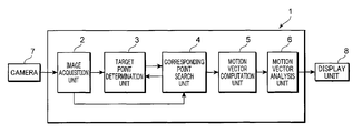
- FIG. 1 is a block diagram showing a configuration of a motion vector generation apparatus according to an embodiment.
- FIG. 2 is a view for use in describing a template, in which FIG. 2(A) is a view showing an image of interest and a reference image when a target point is at a pixel level position, and FIG. 2(B) is a view showing an image of interest and a reference image when a target point is a sub-pixel level.
- FIG. 3 is a view illustrating how to interpolate images.
- FIG. 4 is a view illustrating the window function including the amount of displacement.
- FIG. 5 is a view illustrating a method for shifting the target point to the nearest pixel to search the corresponding point and then correct it.
- FIG. 6 is a view illustrating how to perform the correspondence search.
- FIG. 7 is a view illustrating a method of calculating a three-dimensional motion vector for stereo images.
- FIG. 8 is a view illustrating that three-dimensional motion vectors are linked consecutively in stereo time-series images.
- FIG. 9 is a view illustrating another method of calculating a three-dimensional motion vector in stereo images.
- FIG. 10 is another view illustrating that three-dimensional motion vectors are linked consecutively in stereo time-series images.
- FIG. 11 is a view illustrating a method of assessing reliability of motion vectors.
- FIG. 12 is a view illustrating another method of assessing reliability of motion vectors.
- FIG. 1 is a block diagram showing a configuration of a motion vector generation apparatus according to this embodiment.
- a motion vector generation apparatus 1 comprises an image acquisition unit 2 , a target point determination unit 3 , a corresponding point search unit 4 , a motion vector calculation unit 5 , and a motion vector analysis unit 6 .
- the motion vector generation apparatus 1 is made up of, for example, electronic components and integrated circuit components, a CPU (Central Processing Unit), and a storage unit.
- the motion vector generation apparatus 1 is connected to a camera 7 and a display unit 8 .
- the camera 7 is for taking time-series images and is thus preferably a stereo camera. More specifically, the camera 7 is comprised of two cameras that are placed side by side, spaced apart at a predetermined distance.
- the display unit 8 presents a display of the results obtained by the motion vector generation apparatus 1 .
- the image acquisition unit 2 acquires time-series images from the camera 7 and holds them.
- the stereo cameras of the camera 7 make two simultaneous exposures of the same subject to produce a pair of images, and supply a collection of them as time-series stereo images to the motion vector generation apparatus 1 .
- Two cameras of the camera 7 are placed with parallel optical axes, and optical aberration in the cameras is almost perfectly corrected.
- Such parallel camera geometry in the stereo camera produces parallel images.
- the camera 7 may be a monocular camera rather than a stereo camera.
- the time-series images may be obtained by acquiring images at different timings with a monocular camera.
- the target point determination unit 3 determines a target point on an image (image of interest) among the images stored in the image acquisition unit 2 .
- the image of interest includes the point of origin of a motion vector
- an arbitrary point in that image of interest is used as the target point.
- the corresponding point in an image that has previously been captured is re-defined as the target point.
- the corresponding point search unit 4 searches a point in the reference image that corresponds to the image of interest (correspondence search).
- the reference image refers to an image that corresponds to the image of interest. More specifically, in a stereo image, either one of a pair of images that are taken at the same time is referred to as the image of interest, and the other is referred to as the reference image. In the time-series images, the preceding or previous image of the images taken with the same camera is referred to as the image of interest, and the following or subsequent one is referred to as the reference image.
- a specific procedure of the correspondence search is described.
- a template is defined for the target point that is determined by the target point determination unit 3 .
- a template in the reference image is searched that corresponds to the defined template.
- the corresponding point is found in the searched template. More specifically, the corresponding point search unit 4 takes the image of interest within which the target point is determined by the target point determination unit 3 to define a template containing the target point in the image of interest.
- the template refers to a range confined by a certain region in the image of interest, and has information (image pattern) such as a luminance value of each pixel within this range.
- the corresponding point search unit 4 computes correlation values between the template and each of the windows defined in the reference image that corresponds to the image of interest to determine whether these images correspond to each other according to the correlation value.
- the window herein refers to a region stretched to the same size as the template, and the reference image contains two or more windows defined therein.
- the window has information (image pattern) such as a luminance value of each pixel within this range.
- the correlation value can be computed from the image pattern of the template and the windows. For example, after a correlation value between the template and one of the windows is computed, and if it is determined that they do not correspond to each other because the correlation value is small, a correlation value is computed between the template and a window that is shifted from the latest window by one pixel in either direction. In this way, the window for which the correlation value has a peak value, that is, the window corresponding to the template can be determined.
- the preceding or previous image is used as the image of interest and the following or subsequent image is used as the reference image, for example.
- the following or subsequent image may be used as the image of interest and the preceding or previous image may be used as the reference image.
- the preceding or previous image is used as the image of interest and the following or subsequent image is used as the reference image.
- the preceding or previous image is not necessarily used as the image of interest.
- the following or subsequent image may be used as the image of interest and the preceding or previous image may be used as the reference image.
- the range within which the windows are defined can be limited further.
- Another method is based on a search technique by a multiresolution strategy.
- the resolution is reduced for both the image of interest and the reference image, that is, the number of pixels is decreased before the computation of the correlation value(s).
- coordinates at which the correlation value has the peak value relative to the target point are computed.
- the resolution is restored and the range within which the windows are defined is confined in the area around the coordinates obtained at a lower resolution to obtain the correlation value.
- the image of interest and the reference image each having a lower resolution, the information of the image pattern can be reduced.
- the correlation value under such a circumstance can be computed for a shorter period of time.
- the coordinates at which the correlation value has the peak value at a normal resolution must be present at or near the thus-obtained coordinates at which the correlation value has the peak value at the lower resolution.
- multiple low-resolution images may be generated stepwise to narrow down the area to be searched.
- a function to compute a correlation value is, for example, SAD (Sum of Absolute Difference) algorithm, SSD (Sum of Squared Difference) algorithm, and NCC (Normalize cross Correlation) algorithm.
- SAD Sum of Absolute Difference
- SSD Small of Squared Difference
- NCC Normalize cross Correlation
- the SAD algorithm adds up the absolute values in luminance in the template and window.
- the correlation value for each window can be obtained in accordance with the value given by that function.
- the similarity is computed by using a signal containing only the phase component with the amplitude component being limited from a frequency-resolved signal of an image pattern.
- This approach is insusceptible to, for example, the difference in image-pickup conditions between the right and left cameras for stereo images, and noises, and is therefore applicable to a robust computation of the correlation value(s).
- Known methods of computing the frequency-resolved signal of the image pattern include, for example, fast Fourier transform (FFT), discrete Fourier transform (DFT), discrete cosine transform (DCT), discrete sine transform (DST), wavelet transform, and Hadamard transform.
- FFT fast Fourier transform
- DFT discrete Fourier transform
- DCT discrete cosine transform
- DST discrete sine transform
- wavelet transform and Hadamard transform.
- POC algorithm Phase-Only Correlation
- the template is defined in the image of interest and the windows having the same size are defined in the reference image.
- the correlation value (the POC value) between the template and one of the windows is computed, with the windows being selected one after another in the reference image.
- the window corresponding to the template is computed according to the correlation value.
- the template in the image of interest and the window in the reference image are transformed using the two-dimensional discrete Fourier transform to be standardized.
- they are combined and transformed using the two-dimensional reverse discrete Fourier transform.
- a POC value that is the correlation value can be computed.
- the POC value is computed in a discrete manner for each pixel, so that the similarity can be obtained for each pixel within the window.
- the above-mentioned SAD algorithm relies on the computation to obtain the correlation value on a window by window basis, but the POC algorithm allows the computation of the correlation value for each pixel within the window.
- a correlation value computation method such as the aforementioned POC algorithm, it is unnecessary to shift the window by one pixel each to compute the correlation value as in the case of the SAD algorithm.
- the window is shifted by an amount of some pixels to compute the correlation value. How much it can be shifted depends on the range over which the corresponding point can be searched. However, it is generally said that the range stretches over about a half of the window size.
- the window is shifted so that the shifted window is overlapped with the window before the shift by an amount of about half the window size.
- the window size is equal to 31 ⁇ 31
- the range over which the search can be made by using the POC algorithm is ⁇ 8 pixels with respect to the position of the center of gravity
- the POC algorithm it is possible to use the search method using the above-mentioned multiresolution strategy. In the above-mentioned example, it is enough to define eight windows.
- the image is reduced by 1/16 by using the search method based on the multiresolution strategy, it is necessary to define only one window. This further facilitates the correspondence search.
- Such a technique is known, other than the POC algorithm, that the correlation value is computed by using a signal containing only the phase component with the amplitude component being limited from a frequency-resolved signal of an image pattern.
- An example includes a DCT sign-only correlation algorithm which may be used to perform the computation of the correlation value.
- the DCT sign-only correlation algorithm is a known algorithm and is disclosed in, for example, “Combining image signal processing and image pattern recognition-DCT sign-only correlation and its application”, Hitoshi KIYA, Faculty of System Design, Tokyo Metropolitan University, JPSE Workshop on Dynamic Image Processing for Real Application, 2007, Mar. 8 and 9, 2007.
- the search is performed at the sub-pixel level, so that the window(s) within the reference image is defined at the sub-pixel level rather than at the pixel level.
- a whole single pixel is not necessarily included in a window, and a part of the pixel may be included in that window. This means that the window does not necessarily confine a region with pixel accuracy.
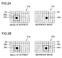
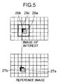
- FIG. 2 is a view for use in describing a template, in which FIG. 2(A) is a view showing an image of interest and a reference image when a target point is at a pixel level position, and FIG. 2(B) is a view showing an image of interest and a reference image when a target point is at a sub-pixel level.
- FIG. 2(A) when a target point in a image of interest 21 a having several pixels 22 is at a pixel level position, a template 25 a of, for example, 3 by 3 is defined on the image of interest 21 a , with a target point 24 a being given as a position of the center of gravity.
- a window of 3 by 3 is defined on a reference image 21 b having several pixels 22 .
- the similarity between a pattern of the image in the template 25 a in the image of interest 21 a and a pattern of the image in the window in the reference image 21 b , thereby a corresponding point 24 b is determined.
- the sub-pixel level position can be obtained as shown in FIG. 2(A) by using, for example, interpolation during the search of the corresponding point 24 b.
- a window made up of units of pixels cannot be defined. If it is necessary to define such a window, for example, the position of the target point 24 c should be corrected to the position of the center of gravity of the pixel. However, this only produces a value that is displaced from the expected value. Taking this into consideration, the target point 24 c is placed at the position of the center of gravity and the template 25 b of 3 by 3 is defined without using the units of pixels. Then, the correlation value with respect to the window 25 c in the reference image 21 b is computed.
- the resulting correlation value is used to define the window 25 c corresponding to the template 25 b .
- the position of the center of gravity of that window 25 c is computed as the corresponding point 24 d .
- the target point 24 a , the corresponding point 24 b , the target point 24 c , and the corresponding point 24 d are all dots in practice, but they are illustrated to have the same size as the pixels in FIGS. 2(A) and 2(B) , for the purpose of better visualization.
- the template is defined at the sub-pixel level position, and therefore, the image pattern should be computed according to the arrangement of the pixels.
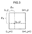
- FIG. 3 is a view illustrating how to interpolate images.
- (i, j), (i+1, j), (i, j+1), and (i+1, j+1) each represents the position of a pixel
- (x, y) represents the coordinates of the target point at the sub-pixel level position.
- a luminance value at (x, y) should be determined.
- the luminance values for the pixels located around (x, y) are used to provide the luminance value at (x, y) by means of interpolation.
- the luminance value at (x, y) is determined by the interpolation using the luminance values for the pixels at (i, j), (i+1, j), (i, j+1), and (i+1, j+1) that surround (x, y).
- the luminance value at the sub-pixel level position that is shifted from the pixel level position is determined to obtain the image pattern for the template.
- the template can thus be defined.
- the luminance value I(x, y) at (x, y) is given in which the bilinear interpolation is used.
- I(i, j), I(i+1, j), I(i, j+1), and I(i+1, j+1) represent the luminance values for the respective pixels.
- the Equation 1 represents the coordinates position of (x, y), while the Equation 2 represents the luminance value thereof.
- i and j are integers, respectively, ⁇ x and ⁇ y, are each a numeral that is larger than 0 but smaller than 1.
- I ⁇ ( x , y ) ( i + ⁇ ⁇ ⁇ x , j + ⁇ ⁇ ⁇ y ) ⁇ ... ( 1 )
- I ⁇ ( x , y ) ⁇ ( 1 - ⁇ ⁇ ⁇ x ) ⁇ ( 1 - ⁇ ⁇ ⁇ y ) ⁇ I ⁇ ( i , j ) ⁇ + ⁇ ( 1 - ⁇ ⁇ ⁇ x ) ⁇ ⁇ ⁇ ⁇ y ⁇ I ⁇ ( i + 1 , j ) ⁇ + ⁇ ⁇ ⁇ ⁇ x ⁇ ( 1 - ⁇ ⁇ ⁇ y ) ⁇ I ⁇ ( i , j + 1 ) ⁇ + ⁇ ⁇ ⁇ ⁇ x ⁇ ⁇ ⁇ ⁇ y ⁇ I ⁇ ( i , j + 1 ) ⁇ + ⁇ ⁇ ⁇ ⁇ x ⁇ ⁇
- the luminance value at the sub-pixel level position may be obtained to define the template using interpolation other than the bilinear interpolation.
- the interpolation may be performed by using, for example, the bicubic interpolation. This makes it possible to define the template.
- a second method of defining the template of which center of gravity is located at the sub-pixel level position is to apply a window function.
- the frequency is generally resolved after the application of the window function in order to avoid, for example, any effect of discontinuity for the frequency resolution.
- the window functions include Hanning window, Hamming window, and Kaiser window.
- the window function includes the amount of displacement from the position of the pixel at the target point at the sub-pixel level position.
- the template can be defined that has the image pattern at the sub-pixel level by applying the window function. Accordingly, how to add the amount of displacement to the window function is described.
- Hanning window is used for description.
- Equation 3 The equation of the Hanning window is given by Equation 3:
- Equation 3 represents a one-dimensional Hanning window. It is easy to transform it into a two-dimensional function.
- An equation representing a two-dimensional Hanning window is given by the Equation 4:
- Equation 5 The window function to be applied, which is obtained by taking the amount of displacement of the target point at the sub-pixel level position into the Equation 4, is given by the Equation 5:
- DH ⁇ ( i , j ) 1 + cos ⁇ ( ⁇ ⁇ ( i + ⁇ ⁇ ⁇ x ) M ) 2 ⁇ 1 + cos ⁇ ( ⁇ ⁇ ( j + ⁇ ⁇ ⁇ y ) N ) 2 ( 5 )
- FIG. 4 is a view illustrating the window function including the amount of displacement.
- FIG. 3 shows one-dimensional (x direction) functions, i.e., a window function with no amount of displacement ( ⁇ ) and a window function with any amount of displacement ⁇ x of 0.5 ( ⁇ ). As apparent from FIG. 4 , they are displaced from each other.
- the second method applies the window function including the amount of displacement that has been obtained, and then resolves the frequency, to perform matching using, for example, the POC algorithm.
- the template of which center of gravity is located at the sub-pixel level position can be defined.
- the amount of displacement may be included in a similar manner into a window function other than the Hanning window. This makes it possible to define the template of which center of gravity is located at the sub-pixel level position.
- a third method of defining the template of which center of gravity is located at the sub-pixel level position is to rotate a phase component in a frequency domain.
- the template can be defined by rotating the phase component in the frequency domain. This allows fast correspondence search.
- This method of rotating the phase component in the frequency domain is a known technique, and is disclosed in, for example, “A High-Accuracy Passive 3D Measurement System Using Phase-Based Image Matching”, IEICE Transactions. Fundamentals, March 2006, E89-A, no. 3, pp. 686-697, in particular, page 688, right column, lines 19 to 32 of this article.
- FIG. 5 is a view illustrating a method for shifting the target point to the nearest pixel to search the corresponding point and then correct it.
- a target point 26 a is displaced from the position of the center of gravity of the pixel.
- a template 26 c is defined of which center of gravity is located at a pixel 26 b that is nearest to the target point 26 a . Then, a corresponding point 27 b in the reference image which corresponds to the center of gravity of the pixel 26 b is searched. Subsequently, in the image of interest, a corresponding point 27 a corresponding to the target point 26 a is defined by shifting the corresponding point 27 b by an amount equal to the amount of displacement ⁇ from the center of gravity of the pixel 26 b shifted from the target point 26 a .
- a vector representing the amount of displacement ⁇ can be given by (x1 ⁇ x2, y1 ⁇ y2).
- coordinates of the corresponding point 27 b to the position of the center of gravity of the pixel 26 b be (x3, y3)
- the coordinates of the corresponding point 27 a to the target point 26 a can be obtained by adding a vector representing the amount of displacement ⁇ .
- the coordinates of the corresponding point 27 a is given by (x1+x1 ⁇ x2, y1+y1 ⁇ y2).
- the corresponding point search unit 4 is only required to search the corresponding point at the sub-pixel level with respect to the target point at the sub-pixel level.
- the target point in the image of interest may be given at the pixel level rather than with sub-pixel accuracy because resolution is coarse in the correspondence search using low resolution. This makes it possible to narrow down the range for the corresponding window, and the time required for the correspondence search using under a low resolution circumstance can further be reduced.
- the matching may be performed at the sub-pixel level with low resolution as well.
- FIG. 6 is a view illustrating how to perform the correspondence search between images captured with a monocular camera.
- illustrated are images captured with the monocular camera at time instants T 1 , T 2 , and T 3 .
- the target point is defined with the image at the time instant T 1 used as the image of interest. This image is the first one, and the target point therein serves as the starting point. Accordingly, the target point is defined at the pixel level, i.e., in a unit of a pixel.
- each small square represents one pixel. Therefore, the target point at the pixel level is located at the center of gravity of the small square. On the other hand, if it is at the sub-pixel level, the target point is not necessarily the position of the center of gravity of the small square.
- the points 31 , 32 , and 33 are all dots in practice, but they are illustrated to have the same size as the pixels in FIG. 6 , for the purpose of better visualization.
- the images captured with the camera 7 are stored on the image acquisition unit 2 , so that the target point determination unit 3 acquires the image at the time instant T 1 from the image acquisition unit 2 to determine the target point. For example, the point 31 is determined as the target point.
- the corresponding point search unit 4 acquires, from the image acquisition unit 2 , the image at the time instant T 2 corresponding to the image at the time instant T 1 to determine the point 32 that is the corresponding point to the point 31 .
- the image at the time instant T 1 serves as the image of interest and the image at the time instant T 2 serves as the reference image.
- the point 32 is found at the sub-pixel level.
- the corresponding point search unit 4 finds the corresponding point in the image at the time instant T 3 .
- the point 32 which is the corresponding point to the target point in the image at the time instant T 1 serves as the target point.
- the target point determination unit 2 determines the point 32 in the image at the time instant T 2 as the target point.
- the corresponding point search unit 4 obtains the image at the time instant T 3 corresponding to the image at the time instant T 2 from the image acquisition unit 2 to find a point 33 that is the corresponding point to the point 32 .
- the image at the time instant T 2 serves as the image of interest and the image at the time instant T 3 serves as the reference image.
- the point 33 is found at the sub-pixel level.
- the correspondence search method to be used may be any one of the above-mentioned methods.
- the correspondence search is performed at the sub-pixel level, thereby finding points corresponding to the points at the sub-pixel level.
- the motion vector is calculated from the value of the coordinates of the corresponding point in each of the time-series images obtained by the corresponding point search unit 4 as described above. More specifically, calculated are, for example, the distance information, the two-dimensional motion vector, and the three-dimensional motion vector, from, for example, the corresponding point and the target point found by the corresponding point search unit 4 .
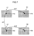
- FIG. 7 is a view illustrating a method of calculating a three-dimensional motion vector for stereo images. Now, with reference to FIG. 7 , how to calculate the three-dimensional motion vector is described.
- an image L 1 and an image R 1 are shown which are stereo images taken at the time instant T 1 .
- the cameras are arranged in parallel to each other in the stereo camera where a pair of two cameras that have taken these images are arranged side by side.
- an image L 2 and an image R 2 taken at the time instant T 2 which is the time instant after the time instant T 1 .
- a point 41 a in the image L 1 at the time instant T 1 is provided as the target point (starting point).
- a point 41 b in the image R 1 point corresponding to the point 41 a is found using the correspondence search.
- a point 42 a corresponding to the point 41 a in the image L 2 at the time instant T 2 is found using the correspondence search.
- the point 42 a is used as the target point to find a point 42 b corresponding to this in the image R 2 at the time instant T 2 using the correspondence search.
- the points 41 a , 41 b , 42 a , and 42 b are all dots in practice, but they are illustrated to have the same size as the pixels in FIG. 7 , for the purpose of better visualization.
- the coordinates of the point 41 a is (p1x, p1y), the coordinates of the point 41 b is (q1x, q1y), the coordinates of the point 42 a is (p2x, p1y), and the coordinates of the point 42 b is (q2x, q2y).
- the vertical direction of the figure is the Y direction of each image while the horizontal direction is the X direction of each image.
- the cameras are arranged in parallel to each other, so that the Y coordinate of the point 41 a is collinear with that of the point 41 b .
- the Y coordinate of the point 42 a is collinear with that of the point 42 b.
- a vector ⁇ d 1 indicating the disparity between the images L 1 and R 1 can be computed from the point 41 a and the coordinates of the point 41 b obtained using the point 41 a .
- ⁇ d 1 is (q1x ⁇ p1x, 0).
- a vector ⁇ f 1 indicating motion in the image L 1 and L 2 can be computed from the point 41 a and the coordinates of the point 42 a obtained using the point 41 a .
- ⁇ f 1 is (p2x ⁇ p1x, p2y ⁇ p1y).
- a vector ⁇ d 2 indicating the disparity between the images at the time instant T 2 can be computed from the point 42 a and the coordinates of the point 42 b obtained using the point 42 a .
- ⁇ d 2 is (q2x ⁇ p2x, 0).
- a depth distance D 1 of an image obtained using the image at the time instant T 1 is determined according to ⁇ d 1 .
- ⁇ d 1 the coordinate in the direction perpendicular to the plane of the drawing in FIG. 7 , and the coordinate is referred to as a Z coordinate.
- f the focal length of each camera of the stereo camera that has taken the images L 1 , R 1 , L 2 , and R 2 , and let a base length between the cameras be B
- D 1 can be given by the Equation 7.
- ⁇ d 1 represents the magnitude of a vector.
- D 1 fB/ ⁇ d 1 (7)
- a depth (Z coordinate direction) distance D 2 of an image obtained using the image at the time instant T 2 is given by the Equation 8 using ⁇ d 2 .
- ⁇ d 2 represents the magnitude of a vector.
- D 2 fB/ ⁇ d 2 (8)
- the three-dimensional coordinates (X1, Y1, Z1) of the points 41 a and 41 b at the time instant T 1 can be given by (p1x ⁇ D1/f, p1y ⁇ D1/f, D1), while the three-dimensional coordinates (X2, Y2, Z2) of the points 42 a and 42 b at the time instant T 2 can be given by (p2x ⁇ D2/f, p2y ⁇ D2/f, D2).
- the three-dimensional motion vector can be computed according to the three-dimensional coordinates (X1, Y1, Z1), and (X2, Y2, Z2). Specifically, the three-dimensional motion vector is a vector given by (X2 ⁇ X1, Y2 ⁇ Y1, Z2 ⁇ Z1).
- the two-dimensional motion vector is calculated from the time-series images captured with the monocular camera. In this case, only the images captured with one of the cameras should be taken into consideration from the images captured with the aforementioned stereo camera. For example, the images L 1 and L 2 are captured and the point 42 a corresponding to the point 41 a is searched. Then, the two-dimensional motion vector is computed from the points 41 a and 42 a . In other words, the two-dimensional motion vector can be given by the aforementioned ⁇ f 1 .
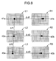
- FIG. 8 is a view illustrating that three-dimensional motion vectors are linked consecutively in stereo time-series images.
- the image L 1 and the image R 1 that are stereo images taken at the time instant T 1
- the image L 2 and the image R 2 taken at the time instant T 2
- an image L 3 and an image R 3 taken at the time instant T 3 taken at the time instant T 3 .
- the point 41 b that is the corresponding point in the image R 1 at the time instant T 1 is found using the correspondence search.
- Computation of the point 41 b provides ⁇ d 1 .
- the point 42 a in the image L 2 at the time instant T 2 that is the point corresponding to the point 41 a in the image L 1 is found using the correspondence search.
- Computation of the point 42 a provides ⁇ f 1 .
- the point 42 b in the image R 2 at the time instant T 2 that corresponds to the point 42 a in the image L 2 is found using the correspondence search.
- Computation of the point 42 b provides ⁇ d 2 .
- the vectors ⁇ d 1 , ⁇ d 2 , and ⁇ f 1 are used to compute the three-dimensional motion vector between the time instant T 1 and the time instant T 2 as described above.
- a point 43 a which is the corresponding point in the image L 3 at the time instant T 3 , corresponding to the point 42 a in the image L 2 at the time instant T 2 is found using the correspondence search. Computation of the point 43 a provides ⁇ f 2 . Then, a point 43 b in the image L 3 at the time instant T 3 which is the point corresponding to the point 43 a in the image L 3 is found using the correspondence search. Computation of the point 43 b provides ⁇ d 3 .
- the vectors ⁇ d 2 , ⁇ d 3 , and ⁇ f 2 are used to compute the three-dimensional motion vector between the time instant T 1 and the time instant T 2 as well as the three-dimensional motion vector between the time instant T 2 and the time instant T 3 .
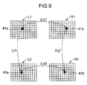
- FIG. 9 is a view illustrating another method of calculating a three-dimensional motion vector in stereo images.
- the images shown in FIG. 9 are similar to the images in FIG. 7 , but how to find the point 42 b is different from the method described in conjunction with FIG. 7 . More specifically, first, it is assumed that the point 41 a in the image L 1 at the time instant T 1 is provided as the target point (starting point). The point 41 b in the image R 1 that is the point corresponding to the point 41 a is provided. In addition, when the point 41 a is used as the target point, the point 42 a corresponding to the point 41 a is found in the image L 2 at the time instant T 2 . Then, the point 41 b is used as the target point to find the point 42 b in the image R 2 which corresponds to it is found using the correspondence search.
- the vector ⁇ d 1 indicating the disparity between the images L 1 and R 1 is computed from the point 41 a and the coordinates of the point 41 b obtained using the point 41 a .
- ⁇ d 1 is (q1x ⁇ p1x, 0).
- the vector ⁇ f 1 indicating motion in the image L 1 and L 2 is computed from the point 41 a and the coordinates of the point 42 a obtained using the point 41 a .
- ⁇ f 1 is (p2x ⁇ p1x, p2y ⁇ p1y).
- a vector ⁇ g 1 indicating the disparity between the images R 1 and R 2 is computed from the point 41 b and the coordinates of the point 42 b obtained using the point 41 b.
- the distances D 1 and D 2 are obtained using ⁇ d 1 , ⁇ d 2 , the focal length f, the base length B, the Equation 7, and the Equation 8, from which the three-dimensional motion vector can be computed as described above.
- the three-dimensional coordinates (X1, Y1, Z1) of the points 41 a and 41 b at the time instant T 1 can be given by (p1x ⁇ D1/f, p1y ⁇ D1/f, D1)
- the three-dimensional coordinates (X2, Y2, Z2) of the points 42 a and 42 b at the time instant T 2 can be given by (p2x ⁇ D2/f, p2y ⁇ D2/f, D2).
- the three-dimensional motion vector is a vector given by (X2 ⁇ X1, Y2 ⁇ Y1, Z2 ⁇ Z1).
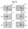
- FIG. 10 is another view illustrating that three-dimensional motion vectors are linked consecutively in stereo time-series images.
- the image L 1 and the image R 1 that are stereo images taken at the time instant T 1
- the image L 2 and the image R 2 taken at the time instant T 2
- an image L 3 and an image R 3 taken at the time instant T 3 taken at the time instant T 3 .
- the point 41 b that is the corresponding point in the image R 1 at the time instant T 1 is found using the correspondence search.
- Computation of the point 41 b provides ⁇ d 1 .
- the point 42 a in the image L 2 at the time instant T 2 that is the point corresponding to the point 41 a in the image L 1 is found using the correspondence search.
- Computation of the point 42 a provides ⁇ f 1 .
- the point 42 b in the image R 2 at the time instant T 2 that corresponds to the point 41 b in the image R 1 is found using the correspondence search.
- Computation of the point 42 b provides ⁇ g 1 .
- the vectors ⁇ d 1 , ⁇ f 1 , and ⁇ g 1 are used to compute the three-dimensional motion vector between the time instant T 1 and the time instant T 2 as described above.
- a point 43 a which is the corresponding point in the image L 3 at the time instant T 3 , corresponding to the point 42 a in the image L 2 at the time instant T 2 is found using the correspondence search. Computation of the point 43 a provides ⁇ f 2 . Then, a point 43 b in the image R 3 at the time instant T 3 which is the point corresponding to the point 42 b in the image R 2 is found using the correspondence search. Computation of the point 43 b provides ⁇ g 2 .
- the vectors ⁇ d 1 , ⁇ f 1 , ⁇ g 1 , ⁇ f 2 , and ⁇ g 2 are used to compute the three-dimensional motion vector between the time instant T 1 and the time instant T 2 as well as the three-dimensional motion vector between the time instant T 2 and the time instant T 3 .
- the correspondence search technique for calculating motion vectors in the time-series stereo images there are two methods as shown in FIGS. 7 and 8 as well as FIGS. 9 and 10 .
- the corresponding point search unit 4 performs the correspondence search using either method and, in response to this, the motion vector calculation unit 5 calculates the motion vector. It is preferable for the corresponding point search unit 4 to use the same correlation value operation (the SAD algorithm, the POC algorithm, or other method) even when there are different reference images when, for example, a corresponding point in two or more reference images is searched with respect to the same target point during the correspondence search. In other words, in such circumstances, a common template can be shared among the reference images for the target point, which provides an effect of simplifying the computation operation.
- the correlation value computation operation used by the corresponding point search unit 4 is one of the computation methods.
- a robust correlation value computation method such as the aforementioned POC algorithm
- the correlation value computation method when the corresponding point in two or more reference images is searched with respect to the same target point, it is preferable to use the same image pattern of the template of which frequency is resolved and amplitude component is restricted even when there are different reference images. With such a configuration, the image pattern of the template of which frequency is resolved and amplitude component is restricted can be shared, which provides an effect of reducing the operation process time.
- the correspondence search technique for calculating motion vectors in the time-series stereo images there are two methods. For example, as shown in FIG. 8 , the method in which the corresponding point is found in one of a pair of stereo images, and as shown in FIG. 10 , the method in which the corresponding point is found based on the image that has taken previously.
- the images L 2 and L 3 are used in order to find the corresponding point in the images R 2 and R 3 .
- the images R 1 and R 2 are used in order to find the corresponding point in the images R 2 and R 3 .
- the same corresponding point can be given from two or more target points.
- the corresponding point search unit 4 searches a single corresponding point to two or more target points among the aforementioned two or more target points, and determines that the calculated motion vector is highly reliable when the same corresponding point is found therefrom, and that the calculated motion vector is not reliable when different corresponding points are given therefrom.
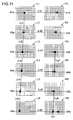
- FIG. 11 is a view illustrating a method of assessing reliability of motion vectors.
- the images L 1 to L 6 and the images R 1 to R 6 which are stereo time-series images at the time instants T 1 to T 6 .
- the images L 1 to L 6 and the images R 1 to R 6 are corresponding to each other.
- the corresponding point search unit 4 and the motion vector calculation unit 5 use the point 41 a in the image L 1 as the target point (starting point) to find the point 41 b in the image R 1 using the correspondence search to provide ⁇ d 1 .
- the point 42 a in the image L 2 corresponding to the point 41 a in the image L 1 is found using the correspondence search to provide ⁇ f 1 .
- the point 42 b in the image R 2 corresponding to the point 42 a in the image L 2 is found using the correspondence search to provide ⁇ d 2 .
- the point 43 a in the image L 3 corresponding to the point 42 a in the image L 2 is found using the correspondence search to provide ⁇ f 2 .
- the point 43 b in the image R 3 corresponding to the point 43 a in the image L 3 is found using the correspondence search to provide ⁇ d 3 .
- a point 44 a in the image L 4 corresponding to the point 43 a in the image L 3 is found using the correspondence search to provide ⁇ f 3 .
- a point 44 b in the image R 4 corresponding to the point 44 a in the image L 4 is found using the correspondence search to provide ⁇ d 4 .
- a point in the image R 4 corresponding to the point 43 b in the image R 3 is found using the correspondence search to provide ⁇ g 3 .
- the point 44 b is searched from two points 44 a and 43 b .
- the same point 44 b is searched from both points, so that the reliability of the correspondence search can be considered to be high.
- the corresponding point corresponding to two points is searched for the aforementioned two points to check whether the same point can be searched, thereby the reliability of the correspondence search can be assessed.
- the corresponding point search unit 4 and the motion vector calculation unit 5 continue the correspondence search and calculation of motion vectors.
- a point 45 a in the image L 5 corresponding to the point 44 a in the image L 4 is found using the correspondence search to provide ⁇ f 4 .
- a point 45 b in the image R 5 corresponding to the point 45 a in the image L 5 is found using the correspondence search to provide ⁇ d 5 .
- a point 46 a in the image L 6 corresponding to the point 45 a in the image L 5 is found using the correspondence search to provide ⁇ f 5 .
- a point 46 b in the image R 6 corresponding to the point 46 a in the image L 6 is found using the correspondence search to provide ⁇ d 6 .
- a point 46 c in an image R 6 corresponding to a point 45 b in an image R 5 is found using the correspondence search to provide ⁇ g 5 .
- the point 46 b and the point 46 c must have the same coordinates, but they have different coordinates. Accordingly, in this case, it is said that the reliability of the correspondence search is low.
- the motion vector generation apparatus 1 of the embodiment detects an error.
- the operation of the motion vector generation apparatus 1 may be stopped or, alternatively, a corresponding point may further be searched among the searched points for a possibly exact point to calculate a motion vector.
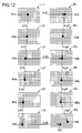
- FIG. 12 is a view illustrating another method of assessing reliability of motion vectors.
- FIG. 12 as in FIG. 11 , there are the images L 1 to L 6 and the images R 1 to R 6 which are stereo time-series images at the time instants T 1 to T 6 .
- the images L 1 to L 6 and the images R 1 to R 6 are corresponding to each other.
- the method of assessing reliability of motion vectors shown in FIG. 12 is different from the one shown in FIG. 11 in the correspondence search and how to calculate the motion vectors.
- the corresponding point search unit 4 and the motion vector calculation unit 5 use the point 41 a in the image L 1 as the target point (starting point) to find the point 41 b in the image R 1 using the correspondence search to provide ⁇ d 1 . Then, the point 42 a in the image L 2 corresponding to the point 41 a in the image L 1 is found using the correspondence search to provide ⁇ f 1 . Then, the point 42 b in the image R 2 corresponding to the point 41 b in the image R 1 is found using the correspondence search to provide ⁇ g 1 . Then, the point 43 a in the image L 3 corresponding to the point 42 a in the image L 2 is found using the correspondence search to provide ⁇ f 2 .
- the point 43 b in the image R 3 corresponding to the point 42 b in the image R 2 is found using the correspondence search to provide ⁇ g 2 .
- a point in the image R 3 corresponding to the point 43 a in the image L 3 is found using the correspondence search to provide ⁇ d 3 .
- the point 43 b is searched from two points 43 a and 42 b .
- the same point 43 b is searched from both points, so that the reliability of the correspondence search can be considered to be high.
- the corresponding point corresponding to two points is searched for the aforementioned two points to check whether the same point can be searched, thereby the reliability of the correspondence search can be assessed.
- the corresponding point search unit 4 and the motion vector calculation unit 5 continue the correspondence search and calculation of motion vectors.
- the point 44 a in the image L 4 corresponding to the point 43 a in the image L 3 is found using the correspondence search to provide ⁇ f 3 .
- the point 44 b in the image R 4 corresponding to the point 43 b in the image R 3 is found using the correspondence search to provide ⁇ g 3 .
- the point 45 a in the image L 5 corresponding to the point 44 a in the image L 4 is found using the correspondence search to provide ⁇ f 4 .
- the point 45 b in the image R 5 corresponding to the point 44 b in the image R 4 is found using the correspondence search to provide ⁇ g 4 .
- the point 46 a in the image L 6 corresponding to the point 45 a in the image L 5 is found using the correspondence search to provide ⁇ f 5 .
- a point 46 b in the image R 6 corresponding to the point 45 b in the image R 5 is found using the correspondence search to provide ⁇ g 5 .
- the point 46 c in the image R 6 corresponding to the point 46 a in the image L 6 is found using the correspondence search to provide ⁇ d 6 .
- the point 46 b and the point 46 c must have the same coordinates, but they have different coordinates.
- the motion vector generation apparatus 1 of the embodiment detects an error.
- the operation of the motion vector generation apparatus 1 may be stopped or, alternatively, a corresponding point may further be searched among the searched points for a possibly exact point to calculate a motion vector.
- the reliability of the correspondence search can be assessed by means of performing, in the case shown in FIG. 11 , the correspondence search among the images taken at different time instants, and in the case shown in FIG. 12 , performing the correspondence search using the stereo images.
- the reliability assessment for the correspondence search may be performed at predetermined time intervals during the passage of time for example. More specifically, it may be performed at predetermined frame intervals. It may be performed depending on the values of the similarity obtained as a result of the computation of the correlation value during the correspondence search. For example, when the POC algorithm is used, the correspondence search may be performed using the two techniques when the POC value is smaller than a predetermined threshold value.
- the correspondence search may be performed using the two techniques when the correlation value is lower than a predetermined threshold value. In these cases, it is likely not to be matched correctly. In addition, it may be performed when a significant change is found relative to preceding motion vector(s). For example, the correspondence search may be performed using the two techniques when the magnitude of the motion vector is increased by two or more times or the direction thereof is changed by 5 degrees or more. Although the motion vector to be compared may be all motion vectors that have previously been calculate, the immediately preceding motion vector may be used for this comparison. In addition, it may be performed depending on the contrast of the defined template. For example, the correspondence search may be performed using the two techniques when the contrast within the template is lower than a predetermined threshold value.
- the motion analysis unit 6 performs a predetermined analysis on the motion vector calculated by the motion vector calculation unit 5 . Specifically, for example, results such as the distance information and the motion vector(s) are converted into a format suitable for being presented on the display unit 8 .
- the camera 7 takes time-series stereo images.
- the images taken with the camera 7 are received by and stored in the image acquisition unit 2 .
- the target point determination unit 3 acquires the image that is used at the beginning of the operation, out of the images stored in the image acquisition unit 2 , and determines the target point to send it to the corresponding point search unit 4 .
- the corresponding point search unit 4 acquires the image corresponding to the image in which the target point has determined by the target point determination unit 3 , out of the images stored in the image acquisition unit 2 , and performs the correspondence search to find the corresponding point to the target point at the sub-pixel level.
- the correspondence search method used may be the above-mentioned method, any method other than the above may be used as long as it can search the corresponding point at the sub-pixel level based on the target point at the sub-pixel level.
- the corresponding point search unit 4 sends the target point and the found corresponding point to the motion vector calculation unit 5 .
- that corresponding point is determined as the target point by the target point determination unit 3 .
- it is sent to the corresponding point search unit 4 and the corresponding point is searched.
- the above-mentioned processing is repeated.
- the corresponding point search unit 4 assesses the reliability of the correspondence search as needed. When the reliability is low, a measure such as stopping the operation may be taken.
- the motion vector calculation unit 5 calculates, for example, the distance information and the motion vectors from the point found by the corresponding point search unit 4 , using the above-mentioned method. Then, the result is sent to the motion vector analysis unit 6 .
- the motion vector analysis unit 6 performs a predetermined analysis in order to, for example, present, for example, the distance information and the motion vector on the display unit 8 . Then, the result of the analysis for the generated motion vector is sent to the display unit 8 and presented thereon.
- the motion vector generation apparatus 1 can directly find the corresponding point to the sub-pixel level position even when the target point is located at that position during the correspondence search.
- the point corresponding to the corresponding point at the computed sub-pixel level position is directly found and it is repeated. This makes it possible to generate a consecutive and highly-accurate motion vector.
- the motion vector generation apparatus 1 has an effect in that a more accurate motion vector can be generated.
- a motion vector generation apparatus comprises an image acquisition unit for acquiring and holding a plurality of images; a target point determination unit for determining a target point at a sub-pixel level in one of the plurality of images held in the image acquisition unit; a corresponding point search unit for searching a corresponding point corresponding to the target point at a sub-pixel level in an image out of the plurality of images held in the image acquisition unit, the image being different from the image in which the target point is determined; and a motion vector calculation unit for calculating a motion vector according to the target point and the corresponding point, the target point determination unit determining, after the corresponding point search unit searches the corresponding point, the searched corresponding point as a target point in the searched image, and the motion vector calculation unit sequentially calculating motion vectors based on the sequentially determined target points and the searched corresponding points corresponding to the target points.
- the motion vector generation apparatus finds the corresponding point for the target point at the sub-pixel level, and finds, at the sub-pixel level, the corresponding point relative to the sub-pixel level position by using the resulting corresponding point as the target point, which is repeated for a plurality of images such as a plurality of time-series images.
- each corresponding point is directly found for each target point, so that the motion vectors computed, for example, in time series are linked consecutively.
- the corresponding points that are sequentially found can be obtained with high accuracy relative to the target point. This allows more precise tracking of the trajectory of the target point.
- the corresponding point search unit defines a template in the image in which the target point is determined, the center of gravity of the template being located at the position of the target point, to search a corresponding point corresponding to the target point at the sub-pixel level, by using the template.
- the motion vector generation apparatus using the template of which position of the center of gravity is defined at the sub-pixel level, the correspondence search is performed.
- the motion vector generation apparatus having such configuration can directly find the point corresponding to the target point at the sub-pixel level, which results in the achievement of highly accurate correspondence search.
- the corresponding point search unit defines a template in the image in which the target point is determined, the center of gravity of the template being located at the position of a pixel that is nearest to the target point, searches a point corresponding to the position of the center of gravity of the pixel using the template, and displaces the position of the searched point by an amount of displacement between the target point and the position of the center of gravity of the pixel that is nearest to the target pixel to search the corresponding point at the sub-pixel level.
- the operation at the pixel level can provide the corresponding point.
- This corresponding point is shifted later to perform the correspondence search at the sub-pixel level.
- the motion vector generation apparatus having such configuration requires a smaller amount of operation in a shorter operation time duration.
- the corresponding point search unit defines a template in the image in which the target point is determined, the center of gravity of the template being located at the position of a pixel that is nearest to the target point, searches, using the template, a point in an image different from the image in which the target point is determined, the point being corresponding to the position of the center of gravity of the pixel, and displaces the position of the searched point by an amount of displacement between the target point and the position of the center of gravity of the pixel that is nearest to the target pixel to search the corresponding point at the sub-pixel level.
- the operation at the pixel level can provide the corresponding point.
- This corresponding point is shifted later to perform the correspondence search at the sub-pixel level.
- the motion vector generation apparatus having such configuration requires a smaller amount of operation in a shorter operation time duration.
- the plurality of images have two or more pairs of stereo images
- the target point determination unit determining the target point at the sub-pixel level in one image of the pair of stereo images
- the corresponding point search unit further searching, at the sub-pixel level, a corresponding point corresponding to the target point in another image that pairs with the image in which the target point is determined.
- the motion vector generation apparatus having such configuration can obtain the distance information by using stereo images.
- the motion vector calculation unit further computes distance information at the time when the pair of stereo images are taken, according to points corresponding to each other between the pair of stereo images, the motion vector calculation unit being configured to use also the distance information in calculating the motion vector.
- the stereo images can be used to obtain the distance information such as the distance from the camera to the target point.
- the motion vector generation apparatus having such configuration can compute a three-dimensional motion vector.
- the plurality of images have two or more pairs of stereo images in time series
- the target point determination unit determining the target point at the sub-pixel level in one image of the pair of stereo images
- the corresponding point search unit searching a corresponding point at the sub-pixel level in an image corresponding to the image in which the target point is determined, the corresponding point being corresponding to the target point, the image being one of the stereo images taken at a time instant that is different from the one at which the image in which the target point is determined is taken
- the target point determination unit determining the corresponding point corresponding to the target point as a target point sequentially searching a corresponding point at the sub-pixel level in an image corresponding to the image in which the target point is determined, the corresponding point being corresponding to the target point, the image being one of the stereo images taken at a time instant that is different from the one at which the image in which the target point is determined is taken, and searching, at the sub-pixel level, a corresponding
- the motion vector generation apparatus by searching the points corresponding to each other between the images of consecutive time-series stereo images, the motion vector generation apparatus having such configuration can obtain the distance information such as the distance from the camera to the target point, and can compute a three-dimensional motion vector.
- the plurality of images have two or more pairs of stereo images in time series
- the target point determination unit determining the target point at the sub-pixel level in one image of the pair of stereo images
- the corresponding point search unit further searching, at the sub-pixel level, a corresponding point corresponding to the target point in another image that pairs with the image in which the target point is determined
- the target point determination unit determining the corresponding point corresponding to the target point in the one image as well as the target point in the other image, as target points, and sequentially searching corresponding points corresponding to the respective target points at the sub-pixel level in an image corresponding to the images having the respective target points, out of a pair of stereo images taken at a time instant that is different from the one at which the images having the respective target points are taken.
- the motion vector generation apparatus by searching the points corresponding to each other between the images of consecutive time-series stereo images, the motion vector generation apparatus having such configuration can obtain the distance information such as the distance from the camera to the target point, and can compute a three-dimensional motion vector.
- the corresponding point search unit generates the template by means of interpolating the image.
- the motion vector generation apparatus having such configuration can use well-known image processing method such as bilinear interpolation (bilinear) and bicubic interpolation (bicubic), and can easily generate an appropriate template for searching.
- image processing method such as bilinear interpolation (bilinear) and bicubic interpolation (bicubic)
- the corresponding point search unit generates the template using a window function.
- a window function is used to generate the template that is arranged at a pseudo sub-pixel level. Therefore, for example, the window function used when the correspondence search is performed using the frequency resolution causes sub-pixel displacement in a pseudo manner to generate the template. Accordingly, the motion vector generation apparatus having such configuration can easily generate an appropriate template.
- the correspondence search is performed using the frequency resolution, no additional processing should be added and fast processing can be made.
- the corresponding point search unit when searching two or more corresponding points that correspond to one target point, uses the same correspondence search method for the search of any corresponding point.
- the template in any correspondence search, can be shared, so that the motion vector generation apparatus having such configuration can reduce the time duration required for defining the template.
- the corresponding point search unit searches one corresponding point according to two or more target points.
- the motion vector generation apparatus having such configuration can assess the reliability of the correspondence search. That is, for example, the correspondence search is performed using two or more target points relative to which the same corresponding point should be found. If the same corresponding point cannot be found, it is possible to consider that the reliability of the correspondence search is low.
- the corresponding point search unit when searching a corresponding point in one image of a pair of stereo images taken at the same time instant based on a point in another image of the pair, searches, under a predetermined condition, the corresponding point based on a point in an image corresponding in time series to the other image, taken at a time instant that is different from the one at which the other image is taken.
- the motion vector generation apparatus having such configuration can assess the reliability of the correspondence search.
- the corresponding point search unit when searching a corresponding point based on a point in an image taken at a different time instant and corresponding in time series, searches, under a predetermined condition, the corresponding point based on a point in one image of a pair of stereo images taken at the same time instant as the image in which the corresponding point is searched.
- the motion vector generation apparatus having such configuration can assess the reliability of the correspondence search.
- the predetermined condition is a predetermined number of frames.
- the motion vector generation apparatus having such configuration assesses the reliability of the above-mentioned correspondence search for every certain number of frames of the time-series images. Thus, it is periodically monitored so that no mis-tracking is caused.
- the predetermined condition is determined according to the similarity in the correspondence search.
- the motion vector generation apparatus having such configuration can assess the reliability of the correspondence search when it is likely that the correspondence search is not correctly performed. That is, when the similarity is low in the correspondence search, it is likely that the correspondence search is not correctly performed. Accordingly, in this case, it can be determined that the correspondence search is possibly wrong.
- the predetermined condition is determined according to the motion vector.
- the motion vector generation apparatus having such configuration can assess the reliability of the correspondence search when it is likely that the correspondence search is not correctly performed. That is, the magnitude or direction of the motion vector is larger than, for example, the one for the immediately preceding motion vector, it is likely that the correspondence search is not correctly performed. Accordingly, in this case, it can be determined that the correspondence search is wrong.
- the predetermined condition is determined according to a contrast in the template.
- the motion vector generation apparatus having such configuration can assess the reliability of the correspondence search when it is likely that the correspondence search is not correctly performed. That is, when the contrast is low in the template, it is likely that the correspondence search is not correctly performed. Accordingly, in this case, it can be determined that the correspondence search is wrong.
- the corresponding point search unit searches a point which corresponds using an image pattern of the template of which frequency is resolved and amplitude component is restricted.
- the motion vector generation apparatus having such configuration restricts the amplitude component from the frequency component. Accordingly, it is insusceptible to the noise or the difference in luminance between images, allowing robust correspondence search.
- the corresponding point search unit when searching two or more corresponding points that correspond to one target point, uses the same image pattern of the template of which frequency is resolved and amplitude component is restricted, for the search of any corresponding point.
- the motion vector generation apparatus having such configuration can share the image pattern of the template of which frequency is resolved and amplitude component is restricted, so that it is possible to reduce the operation processing time.
- the corresponding point search unit generates the template by rotating a phase component of the image pattern in a frequency domain.
- the motion vector generation apparatus having such configuration can generate the template for searching by rotating the phase component in the frequency domain in the correspondence search involving the frequency resolution, which allows fast processing.
- the frequency resolution is either one of FFT, DFT, DCT, DST, wavelet transform, and Hadamard transform.
- the frequency is resolved by using a commonly used and already-established approach, so that the motion vector generation apparatus having such configuration can ensure positive frequency resolution.
- the corresponding point search unit searches a corresponding point using phase-only correlation.
- the motion vector generation apparatus having such configuration allows searching with higher accuracy using the phase-only correlation.
- a motion vector generation method comprises a target point determination step of determining a target point at a sub-pixel level in one image of a plurality of images; a corresponding point search step of searching a corresponding point corresponding to the target point at the sub-pixel level in an image that is different from the image in which the target point is determined, out of the plurality of images; a step of determining the corresponding point searched in the corresponding point search step as a target point in the image in which the corresponding point is searched, and repeating the corresponding point search step; and a motion vector calculation step of calculating a motion vector according to the target point and the corresponding point.
- the motion vector generation method having such procedures generates the motion vectors by means of repeating the steps of determining the corresponding point for the target point at the sub-pixel level, and determining the corresponding point at the sub-pixel level relative to the sub-pixel level position using the determined corresponding point as the target point.
- the generated motion vectors are consecutively linked.
- the corresponding points that are sequentially found are obtained with high accuracy relative to the target point, which results in more precise tracking of the trajectory of the target point.
- a motion vector generation apparatus and a motion vector generation method for generating motion vectors.
Applications Claiming Priority (3)
| Application Number | Priority Date | Filing Date | Title |
|---|---|---|---|
| JP2009-003655 | 2009-01-09 | ||
| JP2009003655 | 2009-01-09 | ||
| PCT/JP2009/071248 WO2010079685A1 (ja) | 2009-01-09 | 2009-12-21 | 動きベクトル生成装置および動きベクトル生成方法 |
Publications (2)
| Publication Number | Publication Date |
|---|---|
| US20110274175A1 US20110274175A1 (en) | 2011-11-10 |
| US9177389B2 true US9177389B2 (en) | 2015-11-03 |
Family
ID=42316454
Family Applications (1)
| Application Number | Title | Priority Date | Filing Date |
|---|---|---|---|
| US13/143,514 Expired - Fee Related US9177389B2 (en) | 2009-01-09 | 2009-12-21 | Motion vector generation apparatus and motion vector generation method |
Country Status (5)
| Country | Link |
|---|---|
| US (1) | US9177389B2 (ja) |
| EP (1) | EP2381418A4 (ja) |
| JP (1) | JP4883223B2 (ja) |
| CN (1) | CN102272796B (ja) |
| WO (1) | WO2010079685A1 (ja) |
Cited By (1)
| Publication number | Priority date | Publication date | Assignee | Title |
|---|---|---|---|---|
| US20190150871A1 (en) * | 2017-11-20 | 2019-05-23 | Konica Minolta, Inc. | Dynamic state imaging system |
Families Citing this family (60)
| Publication number | Priority date | Publication date | Assignee | Title |
|---|---|---|---|---|
| US8866920B2 (en) | 2008-05-20 | 2014-10-21 | Pelican Imaging Corporation | Capturing and processing of images using monolithic camera array with heterogeneous imagers |
| EP4336447A1 (en) | 2008-05-20 | 2024-03-13 | FotoNation Limited | Capturing and processing of images using monolithic camera array with heterogeneous imagers |
| US11792538B2 (en) | 2008-05-20 | 2023-10-17 | Adeia Imaging Llc | Capturing and processing of images including occlusions focused on an image sensor by a lens stack array |
| US8364442B2 (en) * | 2009-02-17 | 2013-01-29 | Schlumberger Technology Corporation | Automated structural interpretation |
| JP5490117B2 (ja) * | 2009-07-07 | 2014-05-14 | 株式会社東芝 | 画像処理装置 |
| EP2502115A4 (en) | 2009-11-20 | 2013-11-06 | Pelican Imaging Corp | RECORDING AND PROCESSING IMAGES THROUGH A MONOLITHIC CAMERA ARRAY WITH HETEROGENIC IMAGE CONVERTER |
| US20120012748A1 (en) | 2010-05-12 | 2012-01-19 | Pelican Imaging Corporation | Architectures for imager arrays and array cameras |
| US8908755B2 (en) * | 2010-07-16 | 2014-12-09 | Sony Corporation | Multi-parameter motion for efficient prediction in video compression |
| US8878950B2 (en) | 2010-12-14 | 2014-11-04 | Pelican Imaging Corporation | Systems and methods for synthesizing high resolution images using super-resolution processes |
| JP2012151796A (ja) * | 2011-01-21 | 2012-08-09 | Sony Corp | 画像処理装置と画像処理方法およびプログラム |
| CN107404609B (zh) | 2011-05-11 | 2020-02-11 | 快图有限公司 | 用于传送阵列照相机图像数据的方法 |
| WO2013001885A1 (ja) * | 2011-06-27 | 2013-01-03 | コニカミノルタホールディングス株式会社 | 画像処理装置、画像処理方法、およびプログラム |
| WO2013043751A1 (en) | 2011-09-19 | 2013-03-28 | Pelican Imaging Corporation | Systems and methods for controlling aliasing in images captured by an array camera for use in super resolution processing using pixel apertures |
| CN104081414B (zh) | 2011-09-28 | 2017-08-01 | Fotonation开曼有限公司 | 用于编码和解码光场图像文件的系统及方法 |
| US9495611B2 (en) * | 2012-01-17 | 2016-11-15 | Konica Minolta, Inc. | Image processing apparatus, image processing method, and image processing program |
| EP2817955B1 (en) | 2012-02-21 | 2018-04-11 | FotoNation Cayman Limited | Systems and methods for the manipulation of captured light field image data |
| WO2014005123A1 (en) | 2012-06-28 | 2014-01-03 | Pelican Imaging Corporation | Systems and methods for detecting defective camera arrays, optic arrays, and sensors |
| US20140002674A1 (en) | 2012-06-30 | 2014-01-02 | Pelican Imaging Corporation | Systems and Methods for Manufacturing Camera Modules Using Active Alignment of Lens Stack Arrays and Sensors |
| BR112015001555A2 (pt) | 2012-07-26 | 2017-07-04 | Olive Medical Corp | vídeo contínuo em ambiente com deficiência de luz |
| KR102127100B1 (ko) | 2012-07-26 | 2020-06-29 | 디퍼이 신테스 프로덕츠, 인코포레이티드 | 광 부족 환경에서 ycbcr 펄싱된 조명 수법 |
| EP3869797B1 (en) | 2012-08-21 | 2023-07-19 | Adeia Imaging LLC | Method for depth detection in images captured using array cameras |
| WO2014032020A2 (en) | 2012-08-23 | 2014-02-27 | Pelican Imaging Corporation | Feature based high resolution motion estimation from low resolution images captured using an array source |
| CN104685860A (zh) | 2012-09-28 | 2015-06-03 | 派力肯影像公司 | 利用虚拟视点从光场生成图像 |
| JP5942771B2 (ja) * | 2012-10-18 | 2016-06-29 | 富士通株式会社 | 画像処理装置及び画像処理方法 |
| US9462164B2 (en) | 2013-02-21 | 2016-10-04 | Pelican Imaging Corporation | Systems and methods for generating compressed light field representation data using captured light fields, array geometry, and parallax information |
| US9917998B2 (en) | 2013-03-08 | 2018-03-13 | Fotonation Cayman Limited | Systems and methods for measuring scene information while capturing images using array cameras |
| US8866912B2 (en) | 2013-03-10 | 2014-10-21 | Pelican Imaging Corporation | System and methods for calibration of an array camera using a single captured image |
| US9888194B2 (en) | 2013-03-13 | 2018-02-06 | Fotonation Cayman Limited | Array camera architecture implementing quantum film image sensors |
| WO2014164550A2 (en) | 2013-03-13 | 2014-10-09 | Pelican Imaging Corporation | System and methods for calibration of an array camera |
| WO2014159779A1 (en) | 2013-03-14 | 2014-10-02 | Pelican Imaging Corporation | Systems and methods for reducing motion blur in images or video in ultra low light with array cameras |
| US9100586B2 (en) | 2013-03-14 | 2015-08-04 | Pelican Imaging Corporation | Systems and methods for photometric normalization in array cameras |
| US9438888B2 (en) | 2013-03-15 | 2016-09-06 | Pelican Imaging Corporation | Systems and methods for stereo imaging with camera arrays |
| US9641815B2 (en) | 2013-03-15 | 2017-05-02 | DePuy Synthes Products, Inc. | Super resolution and color motion artifact correction in a pulsed color imaging system |
| EP2967301B1 (en) | 2013-03-15 | 2021-11-03 | DePuy Synthes Products, Inc. | Scope sensing in a light controlled environment |
| US10122993B2 (en) | 2013-03-15 | 2018-11-06 | Fotonation Limited | Autofocus system for a conventional camera that uses depth information from an array camera |
| US9777913B2 (en) | 2013-03-15 | 2017-10-03 | DePuy Synthes Products, Inc. | Controlling the integral light energy of a laser pulse |
| US9497429B2 (en) | 2013-03-15 | 2016-11-15 | Pelican Imaging Corporation | Extended color processing on pelican array cameras |
| US9445003B1 (en) | 2013-03-15 | 2016-09-13 | Pelican Imaging Corporation | Systems and methods for synthesizing high resolution images using image deconvolution based on motion and depth information |
| WO2015048694A2 (en) | 2013-09-27 | 2015-04-02 | Pelican Imaging Corporation | Systems and methods for depth-assisted perspective distortion correction |
| JP2015078852A (ja) * | 2013-10-15 | 2015-04-23 | 株式会社ディスコ | アライメント方法 |
| US10119808B2 (en) | 2013-11-18 | 2018-11-06 | Fotonation Limited | Systems and methods for estimating depth from projected texture using camera arrays |
| EP3075140B1 (en) | 2013-11-26 | 2018-06-13 | FotoNation Cayman Limited | Array camera configurations incorporating multiple constituent array cameras |
| US10089740B2 (en) | 2014-03-07 | 2018-10-02 | Fotonation Limited | System and methods for depth regularization and semiautomatic interactive matting using RGB-D images |
| CN106102559A (zh) | 2014-03-21 | 2016-11-09 | 德普伊新特斯产品公司 | 用于成像传感器的卡缘连接器 |
| CN113256730B (zh) | 2014-09-29 | 2023-09-05 | 快图有限公司 | 用于阵列相机的动态校准的系统和方法 |
| EP3023938A1 (en) | 2014-11-21 | 2016-05-25 | Thomson Licensing | Method and apparatus for tracking the motion of image content in a video frames sequence using sub-pixel resolution motion estimation |
| US10354365B2 (en) * | 2016-01-18 | 2019-07-16 | Adavanced Micro Devices, Inc. | Hybrid anti-aliasing |
| JP2019028311A (ja) * | 2017-07-31 | 2019-02-21 | キヤノン株式会社 | 視差情報生成装置および視差情報生成方法、撮像装置、移動装置、プログラム |
| US10482618B2 (en) | 2017-08-21 | 2019-11-19 | Fotonation Limited | Systems and methods for hybrid depth regularization |
| JP7273250B2 (ja) | 2019-09-17 | 2023-05-12 | ボストン ポーラリメトリックス,インコーポレイティド | 偏光キューを用いた面モデリングのためのシステム及び方法 |
| US11076151B2 (en) | 2019-09-30 | 2021-07-27 | Ati Technologies Ulc | Hierarchical histogram calculation with application to palette table derivation |
| DE112020004813B4 (de) | 2019-10-07 | 2023-02-09 | Boston Polarimetrics, Inc. | System zur Erweiterung von Sensorsystemen und Bildgebungssystemen mit Polarisation |
| KR20230116068A (ko) | 2019-11-30 | 2023-08-03 | 보스턴 폴라리메트릭스, 인크. | 편광 신호를 이용한 투명 물체 분할을 위한 시스템및 방법 |
| US11195303B2 (en) | 2020-01-29 | 2021-12-07 | Boston Polarimetrics, Inc. | Systems and methods for characterizing object pose detection and measurement systems |
| KR20220133973A (ko) | 2020-01-30 | 2022-10-05 | 인트린식 이노베이션 엘엘씨 | 편광된 이미지들을 포함하는 상이한 이미징 양식들에 대해 통계적 모델들을 훈련하기 위해 데이터를 합성하기 위한 시스템들 및 방법들 |
| US11915337B2 (en) | 2020-03-13 | 2024-02-27 | Advanced Micro Devices, Inc. | Single pass downsampler |
| WO2021243088A1 (en) | 2020-05-27 | 2021-12-02 | Boston Polarimetrics, Inc. | Multi-aperture polarization optical systems using beam splitters |
| US11954886B2 (en) | 2021-04-15 | 2024-04-09 | Intrinsic Innovation Llc | Systems and methods for six-degree of freedom pose estimation of deformable objects |
| US11290658B1 (en) | 2021-04-15 | 2022-03-29 | Boston Polarimetrics, Inc. | Systems and methods for camera exposure control |
| US11689813B2 (en) | 2021-07-01 | 2023-06-27 | Intrinsic Innovation Llc | Systems and methods for high dynamic range imaging using crossed polarizers |
Citations (11)
| Publication number | Priority date | Publication date | Assignee | Title |
|---|---|---|---|---|
| JPH05236452A (ja) | 1991-04-08 | 1993-09-10 | Olympus Optical Co Ltd | 動ベクトル検出方法及び検出装置 |
| JP2001084383A (ja) | 1999-09-09 | 2001-03-30 | Univ Tokyo | 移動検出方法 |
| US20020154820A1 (en) | 2001-03-06 | 2002-10-24 | Toshimitsu Kaneko | Template matching method and image processing device |
| US20020159526A1 (en) * | 2001-03-12 | 2002-10-31 | Hekstra Gerben Johan | Video encoder and video recording apparatus provided with such a video encoder |
| CN1396774A (zh) | 2002-07-12 | 2003-02-12 | 清华大学 | 基于预测方向校正/统计预判的快速亚象素运动估计方法 |
| CN1396744A (zh) | 2001-07-12 | 2003-02-12 | 华为技术有限公司 | 基于gprs业务类型的无线资源规划方法 |
| US20040146183A1 (en) | 2001-02-26 | 2004-07-29 | Yair Shimoni | Method and system for tracking an object |
| CN1741618A (zh) | 2004-09-03 | 2006-03-01 | 北京航空航天大学 | 一种快速亚像素运动估计方法 |
| JP2007257026A (ja) | 2006-03-20 | 2007-10-04 | Clarion Co Ltd | 移動体監視装置 |
| US20080267533A1 (en) * | 2007-04-26 | 2008-10-30 | Kabushiki Kaisha Toshiba | Resolution enhancement apparatus and method |
| CN101340578A (zh) | 2007-07-03 | 2009-01-07 | 株式会社日立制作所 | 运动矢量估计装置、编码器及摄像机 |
Family Cites Families (1)
| Publication number | Priority date | Publication date | Assignee | Title |
|---|---|---|---|---|
| JP2009003655A (ja) | 2007-06-20 | 2009-01-08 | Kyocera Corp | 携帯型電子機器及び電源供給回路 |
-
2009
- 2009-12-21 JP JP2010545699A patent/JP4883223B2/ja not_active Expired - Fee Related
- 2009-12-21 EP EP09837570.2A patent/EP2381418A4/en not_active Withdrawn
- 2009-12-21 WO PCT/JP2009/071248 patent/WO2010079685A1/ja active Application Filing
- 2009-12-21 US US13/143,514 patent/US9177389B2/en not_active Expired - Fee Related
- 2009-12-21 CN CN200980154233.4A patent/CN102272796B/zh not_active Expired - Fee Related
Patent Citations (11)
| Publication number | Priority date | Publication date | Assignee | Title |
|---|---|---|---|---|
| JPH05236452A (ja) | 1991-04-08 | 1993-09-10 | Olympus Optical Co Ltd | 動ベクトル検出方法及び検出装置 |
| JP2001084383A (ja) | 1999-09-09 | 2001-03-30 | Univ Tokyo | 移動検出方法 |
| US20040146183A1 (en) | 2001-02-26 | 2004-07-29 | Yair Shimoni | Method and system for tracking an object |
| US20020154820A1 (en) | 2001-03-06 | 2002-10-24 | Toshimitsu Kaneko | Template matching method and image processing device |
| US20020159526A1 (en) * | 2001-03-12 | 2002-10-31 | Hekstra Gerben Johan | Video encoder and video recording apparatus provided with such a video encoder |
| CN1396744A (zh) | 2001-07-12 | 2003-02-12 | 华为技术有限公司 | 基于gprs业务类型的无线资源规划方法 |
| CN1396774A (zh) | 2002-07-12 | 2003-02-12 | 清华大学 | 基于预测方向校正/统计预判的快速亚象素运动估计方法 |
| CN1741618A (zh) | 2004-09-03 | 2006-03-01 | 北京航空航天大学 | 一种快速亚像素运动估计方法 |
| JP2007257026A (ja) | 2006-03-20 | 2007-10-04 | Clarion Co Ltd | 移動体監視装置 |
| US20080267533A1 (en) * | 2007-04-26 | 2008-10-30 | Kabushiki Kaisha Toshiba | Resolution enhancement apparatus and method |
| CN101340578A (zh) | 2007-07-03 | 2009-01-07 | 株式会社日立制作所 | 运动矢量估计装置、编码器及摄像机 |
Non-Patent Citations (7)
| Title |
|---|
| Argyriou, V.; Vlachos, T. "On the Estimation of Subpixel Motion Using Phase Correlation," J. Elec. Imaging, 2007, 16, 33018. |
| Extended European Search Report from corresponding European Patent Application No. 09837570.2 dated Oct. 10, 2014. |
| International Search Report in International Application No. PCT/JP2009/071248, mailed Feb. 2, 2010, 1 page. |
| Kambhamettu, C.; Palaniappan, K.; Hasler, A.F. "Coupled Multi-Resolution Stereo and Motion Analysis," IEEE, 1995, 43-48. |
| Summary (in English) of the Office Action and Search Report Issued for Chinese Application No. CN 200980154233.4, mailed Mar. 26, 2013, 7 pages. |
| Takita, Kenji, Muquit, Mohammad Abdul, Aoki, Takafumi, and Higuchi, Tatsuo, "A Sub-Pixel Correspondence Search Technique for Computer Vision Applications," IEICE Trans. Fundamentals. , vol. E87-A, No. 8, Aug. 2004, pp. 1913-1923. |
| Tian, Q.; Huhns, M.N. "Algorithms for Subpixel Registration," Computer Vision, Graphics and Image Processing, 1986, 35, 220-233. |
Cited By (2)
| Publication number | Priority date | Publication date | Assignee | Title |
|---|---|---|---|---|
| US20190150871A1 (en) * | 2017-11-20 | 2019-05-23 | Konica Minolta, Inc. | Dynamic state imaging system |
| US10849590B2 (en) * | 2017-11-20 | 2020-12-01 | Konica Minolta, Inc. | Dynamic state imaging system configured to acquire a plurality of images indicating a dynamic state of a subject at predetermined time intervals |
Also Published As
| Publication number | Publication date |
|---|---|
| JPWO2010079685A1 (ja) | 2012-06-21 |
| CN102272796B (zh) | 2014-03-12 |
| WO2010079685A1 (ja) | 2010-07-15 |
| CN102272796A (zh) | 2011-12-07 |
| JP4883223B2 (ja) | 2012-02-22 |
| EP2381418A1 (en) | 2011-10-26 |
| US20110274175A1 (en) | 2011-11-10 |
| EP2381418A4 (en) | 2014-11-12 |
Similar Documents
| Publication | Publication Date | Title |
|---|---|---|
| US9177389B2 (en) | Motion vector generation apparatus and motion vector generation method | |
| US8587666B2 (en) | Object detection from image profiles within sequences of acquired digital images | |
| US8705894B2 (en) | Image rotation from local motion estimates | |
| US11010925B2 (en) | Methods and computer program products for calibrating stereo imaging systems by using a planar mirror | |
| US8587665B2 (en) | Fast rotation estimation of objects in sequences of acquired digital images | |
| US10032278B2 (en) | Vehicle position estimation device, method and computer readable recording medium | |
| US8649593B2 (en) | Image processing apparatus, image processing method, and program | |
| KR100938195B1 (ko) | 스테레오 매칭을 이용한 거리 추정 장치 및 추정 방법 | |
| JP4941565B2 (ja) | 対応点探索装置および対応点探索方法 | |
| US8395659B2 (en) | Moving obstacle detection using images | |
| CN107516322B (zh) | 一种基于对数极空间的图像物体大小和旋转估计计算方法 | |
| US10853960B2 (en) | Stereo matching method and apparatus | |
| US8538137B2 (en) | Image processing apparatus, information processing system, and image processing method | |
| JP2007256029A (ja) | ステレオ画像処理装置 | |
| CN107121132A (zh) | 求取车辆环境图像的方法和设备及识别环境中对象的方法 | |
| JP4862816B2 (ja) | 画像対応点探索装置ならびにそれを用いる測距装置および画像動き検出装置 | |
| EP2657901B1 (en) | Stereo image processing apparatus and stereo image processing method | |
| WO2014010293A1 (ja) | 位置検出装置、および位置検出プログラム | |
| JP6040782B2 (ja) | 画像処理装置及びプログラム | |
| JP2009086882A (ja) | 物体検出装置 | |
| EP2317763A1 (en) | Motion vector detection device and image processing device | |
| US20140003741A1 (en) | Scale changing detection and scaling ratio determination by using motion information | |
| US11176702B2 (en) | 3D image reconstruction processing apparatus, 3D image reconstruction processing method and computer-readable storage medium storing 3D image reconstruction processing program | |
| US20130142388A1 (en) | Arrival time estimation device, arrival time estimation method, arrival time estimation program, and information providing apparatus | |
| US8922648B2 (en) | Rotation cancellation for moving obstacle detection |
Legal Events
| Date | Code | Title | Description |
|---|---|---|---|
| AS | Assignment |
Owner name: KONICA MINOLTA HOLDINGS, INC., JAPAN Free format text: ASSIGNMENT OF ASSIGNORS INTEREST;ASSIGNOR:SUMITOMO, HIRONORI;REEL/FRAME:026778/0176 Effective date: 20110627 |
|
| ZAAA | Notice of allowance and fees due |
Free format text: ORIGINAL CODE: NOA |
|
| ZAAB | Notice of allowance mailed |
Free format text: ORIGINAL CODE: MN/=. |
|
| STCF | Information on status: patent grant |
Free format text: PATENTED CASE |
|
| MAFP | Maintenance fee payment |
Free format text: PAYMENT OF MAINTENANCE FEE, 4TH YEAR, LARGE ENTITY (ORIGINAL EVENT CODE: M1551); ENTITY STATUS OF PATENT OWNER: LARGE ENTITY Year of fee payment: 4 |
|
| FEPP | Fee payment procedure |
Free format text: MAINTENANCE FEE REMINDER MAILED (ORIGINAL EVENT CODE: REM.); ENTITY STATUS OF PATENT OWNER: LARGE ENTITY |
|
| LAPS | Lapse for failure to pay maintenance fees |
Free format text: PATENT EXPIRED FOR FAILURE TO PAY MAINTENANCE FEES (ORIGINAL EVENT CODE: EXP.); ENTITY STATUS OF PATENT OWNER: LARGE ENTITY |
|
| STCH | Information on status: patent discontinuation |
Free format text: PATENT EXPIRED DUE TO NONPAYMENT OF MAINTENANCE FEES UNDER 37 CFR 1.362 |
|
| FP | Lapsed due to failure to pay maintenance fee |
Effective date: 20231103 |