US9162229B2 - Multi-directional sorting with reduced contamination in a flow cytometer - Google Patents
Multi-directional sorting with reduced contamination in a flow cytometer Download PDFInfo
- Publication number
- US9162229B2 US9162229B2 US13/923,480 US201313923480A US9162229B2 US 9162229 B2 US9162229 B2 US 9162229B2 US 201313923480 A US201313923480 A US 201313923480A US 9162229 B2 US9162229 B2 US 9162229B2
- Authority
- US
- United States
- Prior art keywords
- collection
- waste
- sample collector
- droplet stream
- sled
- Prior art date
- Legal status (The legal status is an assumption and is not a legal conclusion. Google has not performed a legal analysis and makes no representation as to the accuracy of the status listed.)
- Active, expires
Links
- 238000011109 contamination Methods 0.000 title abstract description 6
- 239000002699 waste material Substances 0.000 claims abstract description 84
- 239000002245 particle Substances 0.000 claims abstract description 25
- 239000012530 fluid Substances 0.000 claims abstract description 17
- 238000000034 method Methods 0.000 claims description 14
- 230000008878 coupling Effects 0.000 claims 1
- 238000010168 coupling process Methods 0.000 claims 1
- 238000005859 coupling reaction Methods 0.000 claims 1
- 238000000684 flow cytometry Methods 0.000 description 4
- 238000004458 analytical method Methods 0.000 description 2
- 239000011324 bead Substances 0.000 description 2
- 238000012986 modification Methods 0.000 description 2
- 230000004048 modification Effects 0.000 description 2
- 238000000926 separation method Methods 0.000 description 2
- 238000000151 deposition Methods 0.000 description 1
- 230000005684 electric field Effects 0.000 description 1
- 230000010354 integration Effects 0.000 description 1
- 230000007935 neutral effect Effects 0.000 description 1
- 238000005406 washing Methods 0.000 description 1
Images


Classifications
-
- B—PERFORMING OPERATIONS; TRANSPORTING
- B01—PHYSICAL OR CHEMICAL PROCESSES OR APPARATUS IN GENERAL
- B01L—CHEMICAL OR PHYSICAL LABORATORY APPARATUS FOR GENERAL USE
- B01L9/00—Supporting devices; Holding devices
- B01L9/52—Supports specially adapted for flat sample carriers, e.g. for plates, slides, chips
-
- G—PHYSICS
- G01—MEASURING; TESTING
- G01N—INVESTIGATING OR ANALYSING MATERIALS BY DETERMINING THEIR CHEMICAL OR PHYSICAL PROPERTIES
- G01N15/00—Investigating characteristics of particles; Investigating permeability, pore-volume or surface-area of porous materials
- G01N15/10—Investigating individual particles
- G01N15/14—Optical investigation techniques, e.g. flow cytometry
-
- B—PERFORMING OPERATIONS; TRANSPORTING
- B01—PHYSICAL OR CHEMICAL PROCESSES OR APPARATUS IN GENERAL
- B01L—CHEMICAL OR PHYSICAL LABORATORY APPARATUS FOR GENERAL USE
- B01L9/00—Supporting devices; Holding devices
- B01L9/06—Test-tube stands; Test-tube holders
-
- G—PHYSICS
- G01—MEASURING; TESTING
- G01N—INVESTIGATING OR ANALYSING MATERIALS BY DETERMINING THEIR CHEMICAL OR PHYSICAL PROPERTIES
- G01N15/00—Investigating characteristics of particles; Investigating permeability, pore-volume or surface-area of porous materials
- G01N15/10—Investigating individual particles
- G01N15/14—Optical investigation techniques, e.g. flow cytometry
- G01N15/149—Optical investigation techniques, e.g. flow cytometry specially adapted for sorting particles, e.g. by their size or optical properties
-
- G01N2015/149—
-
- G—PHYSICS
- G01—MEASURING; TESTING
- G01N—INVESTIGATING OR ANALYSING MATERIALS BY DETERMINING THEIR CHEMICAL OR PHYSICAL PROPERTIES
- G01N35/00—Automatic analysis not limited to methods or materials provided for in any single one of groups G01N1/00 - G01N33/00; Handling materials therefor
- G01N35/10—Devices for transferring samples or any liquids to, in, or from, the analysis apparatus, e.g. suction devices, injection devices
- G01N35/1009—Characterised by arrangements for controlling the aspiration or dispense of liquids
- G01N35/1011—Control of the position or alignment of the transfer device
Definitions
- Flow cytometers are useful devices for analyzing and sorting various types of particles in fluid streams.
- These cells and particles may be biological or physical samples that are collected for analysis and/or separation.
- the sample is mixed with a sheath fluid for transporting the particles through the flow cytometer.
- the particles may comprise biological cells, calibration beads, physical sample particles, or other particles of interest. Sorting and analysis of these particles can provide valuable information to both researchers and clinicians. In addition, sorted particles can be used for various purposes to achieve a wide variety of desired results.
- An embodiment of the present invention may therefore comprise a collection sled for a flow cytometer comprising: a first sample collector located in a first position to collect samples from a first deflected droplet stream in the flow cytometer, the first sample collector having apertures that accept standard size sample collection tubes; a second sample collector located in a second position to collect samples from a second deflected droplet stream in the flow cytometer, the second sample collector having apertures that accept standard size sample collection tubes, the second sample collector spaced apart from the first sample collector to form a trough between the first sample collector and the second sample collector along a side portion of the first sample collector and a side portion of the second sample collector, the trough being aligned with the waste droplet stream so that the waste droplet stream passes through the trough into a cavity formed by the first sample collector and the second sample collector; a waste stream collector formed from the cavity between the first sample collector and the second sample collector that expands in a downward direction from the trough to prevent backsplash of waste fluid from waste droplets
- An embodiment of the present invention may further comprise a method of collecting a waste droplet stream in a flow cytometer comprising: placing a first sample collector in a first position on a collection sled to collect sample particles from a first deflected droplet stream at a first collection location; placing a second sample collector adjacent to the first sample collector in a second position on the collection sled to collect samples from a second deflected droplet stream at a second collection location, the first sample collector and the second sample collector forming a trough and a cavity for collecting waste fluids from a waste droplet stream; aligning the trough with the waste droplet stream so that the waste droplet stream is collected below the first collection location of the first droplet stream and the second collection location of the second droplet stream; guiding the collection sled in a direction along a single axis so that sample particles from the first deflected droplet stream are collected in a plurality of first collection containers at the first collection location as the collection sled is moved in the direction along the single
- FIG. 1 is a schematic illustration of an embodiment of the present invention.
- FIG. 2 is an isometric view of an embodiment of a collection sled and associated devices.
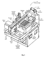
- FIG. 3 is an isometric view of the embodiment of FIG. 2 viewed from a rear location.
- FIG. 4 is an end view of the embodiment of FIGS. 2 and 3 .
- FIG. 5 is another isometric view of portions of the embodiment of FIGS. 2 , 3 and 4 .
- FIG. 6 is an isometric view of an embodiment of an adapter plate.
- FIG. 1 is schematic illustration of an embodiment of a flow cytometer utilizing a collection sled 138 in accordance with one embodiment of the present invention.
- the nozzle 102 generates a stream 126 that comprises sheath fluid from sheath reservoir 106 and sample fluid from sample reservoir 104 .
- the stream 126 is interrogated by interrogation laser 108 .
- Scattered light emitted by sample particles at integration point 124 may be detected by detector 110 .
- Fluorescent emissions from sample particles at interrogation point 124 may be detected by detector 112 .
- the stream 126 breaks off into droplets 130 that form a droplet stream.
- the droplets 130 are charged just prior to breaking off from the stream 126 .
- Controller/analyzer 140 is connected to the detectors 110 , 112 and determines which droplets include particles of interest. The controller/analyzer 140 then provides a signal to the charging unit 142 to generate a charge on the stream 126 just prior to the droplet 130 breaking off from the stream 126 . The remaining droplets are not charged and have a neutral polarity. The droplets containing particles of interest can receive either a negative or positive charge. Charged plates 114 , 116 generate an electric field, which causes charged droplets to deflect into deflected droplet stream 118 and deflected droplet stream 120 .
- the uncharged droplets are not deflected by the charged plates 114 , 116 and form a waste droplet stream 122 that is collected in the waste stream catcher in the collection sled 138 .
- the deflected droplet stream 118 is collected in the left side collector 132
- deflected droplet stream 120 is collected in right side sample collector 134 .
- Existing collectors have typically used a waste stream catcher that is located above the sample collectors, which allows the tray on which the sample collectors are located to move in two dimensions on x,y coordinates under the streams. In that manner, the sample collectors can be accurately positioned to effectively collect the sample.
- Existing systems have also provided movement of the sample collectors in an x,y plane to allow various types of collection containers to be used in the system. For example, it is desirable to use 5 mL test tubes, 8-well strips that can be formed into 96-well plates, and microscope slides.
- Existing systems have allowed movement of the collectors in an x,y plane to accommodate these three different types of collection container formats.
- waste stream catcher If the waste stream catcher is located below the sample collectors, unrestricted movement in an x,y plane is not possible, since such movement would block the waste droplet stream.
- the problem that has been encountered with collecting the waste stream above the sample collectors is that, on occasion, the waste droplet stream 122 may become deflected for some reason, such as an obstruction in the opening in nozzle 102 , incorrect nozzle alignment and other similar issues. When this occurs, the waste droplet stream may impact the edge of the waste stream catcher and cause splashing of waste particles that may land in the sample collectors. The sample is then contaminated, which produces an undesirable result.
- the embodiment illustrated in FIG. 1 has a waste stream catcher 136 that is located below the left side sample collector 132 and right side sample collector 134 . As explained below, the collection sled 138 moves in a single direction inwardly and outwardly from the flow cytometer 100 illustrated in FIG. 1 .
- FIG. 2 is an isometric view of one embodiment of a waste stream catcher 136 .
- the waste stream catcher includes a collection sled 138 that is mounted on top rail 144 and bottom rail 146 .
- Top rail 144 and bottom rail 146 are secured to plate 158 .
- Bearings 148 , 150 are mounted on top rail 144 .
- Similar bearing 172 ( FIG. 4 ) are mounted on the bottom rail 146 .
- Bearings 148 , 150 , as well as bearing 172 are mounted to the side of the collection sled 138 .
- Apertures 160 are formed in the left side sample collector 132 .
- Apertures 162 are formed in the right side sample collector 134 .
- a waste trough 152 is located below apertures 160 , 162 .
- Apertures 160 , 162 have a size and shape to accept a standard 5 mL sample collector, which is the most common form of sample collector.
- the surface of the collection sled 138 is a slanted surface 156 , so that any fluids that are not properly collected flow into the waste trough 152 .
- Camera 164 is a high resolution camera that records the location of the waste droplet stream 122 and the deflected droplet streams 118 , 120 .
- the apertures 160 , 162 are sequentially aligned with the deflected droplet streams 118 , 120 by motor 166 .
- Motor 166 may comprise a stepper motor that is programmed to accurately align the apertures 160 , 162 at the appropriate collection location for collecting the deflected droplet streams 118 , 120 . This process is done automatically using control signals generated by a processor that drives the motor 166 .
- FIG. 3 is an isometric view of the embodiment of FIG. 2 , showing an alternate point of view.
- motor 166 drives a belt 168 .
- a carrier 170 is connected to the belt 168 and to the collection sled 138 .
- motor 166 may comprise a stepper motor that very accurately positions the collection sled 138 with regard to the deflected droplet streams 118 , 120 .
- FIG. 4 is an end view of the embodiment of FIGS. 2 and 3 .
- top rail 144 is engaged by bearing 148 .
- bottom rail 146 is engaged by bearing 172 .
- Bearings 148 , 172 are attached to the plate 174 that forms a portion of the collection sled 138 .
- the left side sample collector 132 is disposed in the collection sled 138 at a first angle.
- right side sample collector 134 is disposed in the collection sled 138 at a similar opposite angle.
- the left side sample collector 132 and the right side sample collector 134 are spaced apart to form a waste trough 152 .
- Waste drain 176 is aligned with the opening in the waste trough 152 to collect the waste droplet stream 122 that falls directly through the waste trough 152 .
- Waste drain 176 is used in one example to collect calibration beads for calibrating the droplet separation location, as disclosed more fully in U.S. Provisional Application Ser. No. 61/656,934, filed Jun. 7, 2012, by Daniel N. Fox, Susan Hunter, Nathan Michael Gaskill-Fox, Kevin P. Raley, and Richard A. Miles, entitled “Automated and Accurate Drop Delay for Flow Cytometry,” which is specifically incorporated herein by reference for all that it discloses and teaches.
- Waste drain 178 collects any other waste that collects in the cavity 180 . Because the opening of the waste trough 152 is the smallest portion of the cavity 180 , the waste droplet stream 122 does not splash upwardly and accidentally contaminate samples that are being collected on the left side sample collector 134 . Further, sample collector tube 182 sits well above the opening of the waste trough 152 to prevent splashes from entering the opening of the sample collector tube 182 . Apertures 160 , 162 are specifically sized to accept standard 5 mL sample collector tubes, such as sample collector tube 182 .
- FIG. 5 is another isometric view of the embodiment of FIGS. 2 , 3 and 4 , illustrating adapter plates 184 , 186 that sit on the top portion of left side sample collector 132 and right side sample collector 134 , respectively.
- an 8-well strip is disposed in adapter plate 184 that is designed to mount an 8-well strip 188 in a collection location for collecting samples in the 8-well strip 188 .
- Sample particles are deposited directly into compartments of the 8-well strip 188 , as the collection sled 138 is moved inwardly and outwardly in housing 192 .
- the 8-well strip 188 can be joined with other 8-well strips to form a 96-well plate that is commonly used in laboratories.
- the adapter plate 186 is illustrated with a microscope slide 190 .
- sorted cells may preferably be deposited on a microscope slide, such as microscope side 190 . Different deposits can be made on the microscope slide 190 , as the collection sled 138 is moved inwardly and outwardly on housing 192 .
- the adapter plates 184 , 186 are adapted to receive either the 8-well strip 188 or the microscope slide 190 .
- the adapter plates 184 , 186 are slanted to provide a flat, horizontal surface for mounting of the 8-well strip 188 and the microscope slide 190 .
- FIG. 6 is an isometric view of an embodiment of an adapter plate 194 .
- the adapter plate 194 includes a slot 196 .
- the slot 196 is dimensioned to receive an 8-well strip, such as 8-well strip 188 .
- the 8-well strip fits snuggly within the slot 916 and can be easily inserted and removed.
- the location of the 8-well strip in the slot 196 is referenced to the body of the adapter plate 194 , so that the collection sled 138 can be accurately positioned, for sorting and depositing sample cells in the 8-well strip that is inserted in the slot 196 .
- the adapter plate 194 includes a recessed portion 198 .
- the recessed portion 198 is surrounded by stops 200 , 202 , 204 , 206 , 208 , 210 .
- the recessed portion 198 is sized so that a standard size microscope plate can be inserted in, and easily removed from, the recessed portion 198 .
- Stops 200 - 210 hold the microscope slide 190 in a predetermined position so that sorted particles can be accurately located on positions of the microscope slide 190 .
- Foot 212 as well as foot 214 , accurately locate the adapter plate 194 on the left side sample collector 132 and right side sample collector 134 , since the feet are adapted to be inserted in the apertures 160 , 162 that are illustrated in FIG. 2 .
- the adapter plate 194 is held in place on the surface of the sample collectors, as a result of foot 212 and foot 214 fitting precisely in the apertures 160 , 162 .
- the embodiments disclosed herein provide a collection sled 138 that has a waste stream catcher 136 that is located below the sample collectors, such as left side sample collector 132 and right side sample collector 134 .
- a waste stream catcher 136 that is located below the sample collectors, splashing and contamination of the waste droplet stream 122 is eliminated.
- the sample collectors are positioned to form a waste trough 152 that extends along the length of the sample collectors and a waste cavity, since the waste trough extends along the length of the sample collectors 132 , 134 , at all locations on the collection sled 138 , as the collection sled 138 is moved in a single direction in and out of the flow cytometer.
- the waste droplet stream 122 is collected in a cavity 180 .
- the sample collector tube 182 is positioned above the waste trough, so that splashing of waste fluid into the sample collector tube does not occur. Additionally, the cavity 180 expands and gets progressively larger after the waste droplet stream 122 enters the waste trough 152 , so that back splash of waste fluid does not occur.
- an adapter plate is provided, which allows for collection of sample particles in an 8-well strip or a microscope slide. Accurate placement of the collection sled 138 is controlled by a stepper motor that is programmed to locate the sample collector tube 182 , the 8-well strip 188 , or the microscope slide 190 in the proper location for collection of sample particles. In this manner, the embodiments disclosed herein allow for collection of fluid using three different formats with the use of a single adapter. Further, contamination of collected samples is reduced because the waste stream catcher 136 is located below the sample collectors.
Landscapes
- Chemical & Material Sciences (AREA)
- Health & Medical Sciences (AREA)
- General Physics & Mathematics (AREA)
- Immunology (AREA)
- Life Sciences & Earth Sciences (AREA)
- Analytical Chemistry (AREA)
- Biochemistry (AREA)
- General Health & Medical Sciences (AREA)
- Pathology (AREA)
- Physics & Mathematics (AREA)
- Dispersion Chemistry (AREA)
- Clinical Laboratory Science (AREA)
- Chemical Kinetics & Catalysis (AREA)
- Apparatus Associated With Microorganisms And Enzymes (AREA)
- Investigating Or Analysing Biological Materials (AREA)
- Sampling And Sample Adjustment (AREA)
Priority Applications (1)
| Application Number | Priority Date | Filing Date | Title |
|---|---|---|---|
| US13/923,480 US9162229B2 (en) | 2012-06-07 | 2013-06-21 | Multi-directional sorting with reduced contamination in a flow cytometer |
Applications Claiming Priority (7)
| Application Number | Priority Date | Filing Date | Title |
|---|---|---|---|
| US201261656934P | 2012-06-07 | 2012-06-07 | |
| US201261659528P | 2012-06-14 | 2012-06-14 | |
| US201261663030P | 2012-06-22 | 2012-06-22 | |
| US201261663026P | 2012-06-22 | 2012-06-22 | |
| US201261663021P | 2012-06-22 | 2012-06-22 | |
| US201261663033P | 2012-06-22 | 2012-06-22 | |
| US13/923,480 US9162229B2 (en) | 2012-06-07 | 2013-06-21 | Multi-directional sorting with reduced contamination in a flow cytometer |
Publications (2)
| Publication Number | Publication Date |
|---|---|
| US20130340539A1 US20130340539A1 (en) | 2013-12-26 |
| US9162229B2 true US9162229B2 (en) | 2015-10-20 |
Family
ID=49769406
Family Applications (1)
| Application Number | Title | Priority Date | Filing Date |
|---|---|---|---|
| US13/923,480 Active 2034-06-10 US9162229B2 (en) | 2012-06-07 | 2013-06-21 | Multi-directional sorting with reduced contamination in a flow cytometer |
Country Status (4)
| Country | Link |
|---|---|
| US (1) | US9162229B2 (zh) |
| EP (1) | EP2864763B1 (zh) |
| CN (1) | CN104508461B (zh) |
| WO (1) | WO2013192479A1 (zh) |
Cited By (7)
| Publication number | Priority date | Publication date | Assignee | Title |
|---|---|---|---|---|
| US20170010203A1 (en) * | 2014-02-14 | 2017-01-12 | Sony Corporation | Particle sorting apparatus, particle sorting method, and non-transitory computer-readable storage medium storing program |
| USD864415S1 (en) | 2018-01-30 | 2019-10-22 | Becton, Dickinson And Company | Particle sorting system |
| USD868991S1 (en) | 2017-03-28 | 2019-12-03 | Becton, Dickinson And Company | Register block |
| USD869676S1 (en) | 2017-03-28 | 2019-12-10 | Becton, Dickinson And Company | Particle sorting module |
| USD872296S1 (en) | 2018-01-30 | 2020-01-07 | Becton, Dickinson And Company | Particle sorting module |
| USD876668S1 (en) | 2018-01-30 | 2020-02-25 | Becton, Dickinson And Company | Particle sorting module mount |
| USD882817S1 (en) | 2018-01-30 | 2020-04-28 | Becton, Dickinson And Company | Sample container |
Families Citing this family (7)
| Publication number | Priority date | Publication date | Assignee | Title |
|---|---|---|---|---|
| JP5973471B2 (ja) | 2011-03-03 | 2016-08-23 | ライフ テクノロジーズ コーポレーション | サンプリングプローブ、システム、装置、および方法 |
| US9366616B2 (en) | 2013-04-12 | 2016-06-14 | Becton, Dickinson And Company | Automated set-up for cell sorting |
| USD787701S1 (en) * | 2014-03-21 | 2017-05-23 | Intellicyt Corporation | Flow cytometer system shelf unit |
| JP6805560B2 (ja) * | 2016-06-10 | 2020-12-23 | ソニー株式会社 | 接続部材及び微小粒子測定装置 |
| CN110935501B (zh) * | 2019-12-30 | 2021-10-19 | 青岛市妇女儿童医院(青岛市妇幼保健院、青岛市残疾儿童医疗康复中心、青岛市新生儿疾病筛查中心) | 一种医疗化验用防交叉感染用的试管架 |
| CN115916409A (zh) * | 2020-06-24 | 2023-04-04 | 贝克顿·迪金森公司 | 流式细胞术液滴分配系统及使用该系统的方法 |
| CN112191295B (zh) * | 2020-10-12 | 2021-09-14 | 厦门市妇幼保健院(厦门市计划生育服务中心、厦门大学附属妇女儿童医院) | 一种单细胞基因组扩增监测器 |
Citations (7)
| Publication number | Priority date | Publication date | Assignee | Title |
|---|---|---|---|---|
| US4009435A (en) | 1973-10-19 | 1977-02-22 | Coulter Electronics, Inc. | Apparatus for preservation and identification of particles analyzed by flow-through apparatus |
| US4667830A (en) | 1981-06-15 | 1987-05-26 | The Board Of Trustees Of The Leland Stanford Junior University | Method and means for sorting individual particles into containers for culturing, cloning, analysis, or the like |
| JPS62167478A (ja) | 1985-11-29 | 1987-07-23 | Shimadzu Corp | 粒子分取装置 |
| US6281018B1 (en) * | 1998-02-26 | 2001-08-28 | Coulter International Corp. | Selective purification and enrichment sorting of flow cytometer droplets based upon analysis of droplet precursor regions |
| US7282707B1 (en) | 2005-06-30 | 2007-10-16 | Thermo Finnigan Llc | Method and apparatus for handling a sample plate for use in mass analysis |
| US20090107893A1 (en) | 2007-10-26 | 2009-04-30 | Becton, Dickinson And Company | Deflection plate |
| US20110033339A1 (en) | 2009-08-06 | 2011-02-10 | Sony Corporation | Microparticle sorting apparatus, flow cytometer using the same and microparticle sorting method |
Family Cites Families (6)
| Publication number | Priority date | Publication date | Assignee | Title |
|---|---|---|---|---|
| US5483469A (en) * | 1993-08-02 | 1996-01-09 | The Regents Of The University Of California | Multiple sort flow cytometer |
| US6211477B1 (en) * | 1998-02-26 | 2001-04-03 | Becton Dickinson And Company | Electrostatic deceleration system for flow cytometer |
| NZ544103A (en) * | 2003-05-15 | 2010-10-29 | Xy Llc | Efficient haploid cell sorting for flow cytometer systems |
| US7691636B2 (en) * | 2007-05-23 | 2010-04-06 | Beckman Coulter, Inc. | Method and apparatus for compensating for variations in particle trajectories in electrostatic sorter for flowcell cytometer |
| US9470617B2 (en) * | 2010-04-07 | 2016-10-18 | Sony Corporation | Flow cytometry apparatus |
| JP5437148B2 (ja) * | 2010-04-23 | 2014-03-12 | ベイバイオサイエンス株式会社 | フローサイトメータおよびセルソータ |
-
2013
- 2013-06-21 CN CN201380032980.7A patent/CN104508461B/zh active Active
- 2013-06-21 US US13/923,480 patent/US9162229B2/en active Active
- 2013-06-21 WO PCT/US2013/046947 patent/WO2013192479A1/en active Application Filing
- 2013-06-21 EP EP13806947.1A patent/EP2864763B1/en active Active
Patent Citations (7)
| Publication number | Priority date | Publication date | Assignee | Title |
|---|---|---|---|---|
| US4009435A (en) | 1973-10-19 | 1977-02-22 | Coulter Electronics, Inc. | Apparatus for preservation and identification of particles analyzed by flow-through apparatus |
| US4667830A (en) | 1981-06-15 | 1987-05-26 | The Board Of Trustees Of The Leland Stanford Junior University | Method and means for sorting individual particles into containers for culturing, cloning, analysis, or the like |
| JPS62167478A (ja) | 1985-11-29 | 1987-07-23 | Shimadzu Corp | 粒子分取装置 |
| US6281018B1 (en) * | 1998-02-26 | 2001-08-28 | Coulter International Corp. | Selective purification and enrichment sorting of flow cytometer droplets based upon analysis of droplet precursor regions |
| US7282707B1 (en) | 2005-06-30 | 2007-10-16 | Thermo Finnigan Llc | Method and apparatus for handling a sample plate for use in mass analysis |
| US20090107893A1 (en) | 2007-10-26 | 2009-04-30 | Becton, Dickinson And Company | Deflection plate |
| US20110033339A1 (en) | 2009-08-06 | 2011-02-10 | Sony Corporation | Microparticle sorting apparatus, flow cytometer using the same and microparticle sorting method |
Non-Patent Citations (1)
| Title |
|---|
| Translation of JP 62167478. * |
Cited By (10)
| Publication number | Priority date | Publication date | Assignee | Title |
|---|---|---|---|---|
| US20170010203A1 (en) * | 2014-02-14 | 2017-01-12 | Sony Corporation | Particle sorting apparatus, particle sorting method, and non-transitory computer-readable storage medium storing program |
| US9804075B2 (en) * | 2014-02-14 | 2017-10-31 | Sony Corporation | Particle sorting apparatus, particle sorting method, and non-transitory computer-readable storage medium storing program |
| US20180045638A1 (en) * | 2014-02-14 | 2018-02-15 | Sony Corporation | Particle sorting apparatus, particle sorting method, and non-transitory computer-readable storage medium storing program |
| US10451534B2 (en) * | 2014-02-14 | 2019-10-22 | Sony Corporation | Particle sorting apparatus and particle sorting method |
| USD868991S1 (en) | 2017-03-28 | 2019-12-03 | Becton, Dickinson And Company | Register block |
| USD869676S1 (en) | 2017-03-28 | 2019-12-10 | Becton, Dickinson And Company | Particle sorting module |
| USD864415S1 (en) | 2018-01-30 | 2019-10-22 | Becton, Dickinson And Company | Particle sorting system |
| USD872296S1 (en) | 2018-01-30 | 2020-01-07 | Becton, Dickinson And Company | Particle sorting module |
| USD876668S1 (en) | 2018-01-30 | 2020-02-25 | Becton, Dickinson And Company | Particle sorting module mount |
| USD882817S1 (en) | 2018-01-30 | 2020-04-28 | Becton, Dickinson And Company | Sample container |
Also Published As
| Publication number | Publication date |
|---|---|
| CN104508461B (zh) | 2018-12-25 |
| EP2864763B1 (en) | 2020-11-11 |
| US20130340539A1 (en) | 2013-12-26 |
| EP2864763A4 (en) | 2016-03-16 |
| CN104508461A (zh) | 2015-04-08 |
| EP2864763A1 (en) | 2015-04-29 |
| WO2013192479A1 (en) | 2013-12-27 |
Similar Documents
| Publication | Publication Date | Title |
|---|---|---|
| US9162229B2 (en) | Multi-directional sorting with reduced contamination in a flow cytometer | |
| US20200309802A1 (en) | Systems and Methods for Automated Analysis | |
| EP2702132B1 (en) | Multi-way sorter system and method | |
| US20180202846A1 (en) | Automated set-up for cell sorting | |
| JP5330504B2 (ja) | データ品質評価および制御機能を備える高スループットフローサイトメータ | |
| CN103364325B (zh) | 微粒分选装置以及确定携带微粒的喷射流轨道的方法 | |
| US20060152708A1 (en) | Multiparametric detection in a fluidic microsystem | |
| US8885041B2 (en) | Method and apparatus for checking the fluid in a pipet tip | |
| CN102762289A (zh) | 生物流体分析卡盒 | |
| CN103926188A (zh) | 一次性芯片型流动室及使用该流动室的流式细胞仪 | |
| EP3951355A1 (en) | Cartridge and device for determining at least the chemical nature of at least solid microplastic particles suspended in a liquid sample | |
| US20230358665A1 (en) | Microfluidic system with combined electrical and optical detection for high accuracy particle sorting and methods thereof | |
| WO2002057775A1 (en) | Electrical conductive containment system | |
| CN109642913A (zh) | 用于检测流体容器中的细胞或颗粒的装置和方法 | |
| EP2299282A2 (en) | Sample processing apparatus, sample transporting device, and sample rack transporting method | |
| US6599480B1 (en) | Apparatus for obtaining increased particle concentration for optical examination | |
| EP2894459A1 (en) | Device for identifying and dispensing samples and method for identifying and dispensing samples | |
| WO2017222461A1 (en) | System and method for precision deposition of liquid droplets | |
| US6867049B1 (en) | Method for obtaining increased particle concentration for optical examination | |
| US20230296522A1 (en) | Measurement apparatus and analysis method | |
| UA12803U (en) | Dropjet method for separation of particles |
Legal Events
| Date | Code | Title | Description |
|---|---|---|---|
| AS | Assignment |
Owner name: PROPEL LABS, INC., COLORADO Free format text: ASSIGNMENT OF ASSIGNORS INTEREST;ASSIGNORS:GASKILL-FOX, NATHAN MICHAEL;FOX, DANIEL N;HARRIS, RODNEY C;REEL/FRAME:030730/0658 Effective date: 20130606 |
|
| AS | Assignment |
Owner name: BIO-RAD LABORATORIES, INC., CALIFORNIA Free format text: ASSIGNMENT OF ASSIGNORS INTEREST;ASSIGNOR:PROP LABS, INC.;REEL/FRAME:031268/0337 Effective date: 20130607 |
|
| STCF | Information on status: patent grant |
Free format text: PATENTED CASE |
|
| AS | Assignment |
Owner name: BIO-RAD LABORATORIES, INC., CALIFORNIA Free format text: ASSIGNMENT OF ASSIGNORS INTEREST;ASSIGNOR:PROPEL LABS, INC.;REEL/FRAME:039372/0995 Effective date: 20120830 |
|
| MAFP | Maintenance fee payment |
Free format text: PAYMENT OF MAINTENANCE FEE, 4TH YEAR, LARGE ENTITY (ORIGINAL EVENT CODE: M1551); ENTITY STATUS OF PATENT OWNER: LARGE ENTITY Year of fee payment: 4 |
|
| MAFP | Maintenance fee payment |
Free format text: PAYMENT OF MAINTENANCE FEE, 8TH YEAR, LARGE ENTITY (ORIGINAL EVENT CODE: M1552); ENTITY STATUS OF PATENT OWNER: LARGE ENTITY Year of fee payment: 8 |