US9095897B2 - Cast-steel pouring apparatus - Google Patents
Cast-steel pouring apparatus Download PDFInfo
- Publication number
- US9095897B2 US9095897B2 US13/985,696 US201213985696A US9095897B2 US 9095897 B2 US9095897 B2 US 9095897B2 US 201213985696 A US201213985696 A US 201213985696A US 9095897 B2 US9095897 B2 US 9095897B2
- Authority
- US
- United States
- Prior art keywords
- steel
- pivot
- outing
- furnace body
- pivot shaft
- Prior art date
- Legal status (The legal status is an assumption and is not a legal conclusion. Google has not performed a legal analysis and makes no representation as to the accuracy of the status listed.)
- Expired - Fee Related, expires
Links
Images


Classifications
-
- B—PERFORMING OPERATIONS; TRANSPORTING
- B22—CASTING; POWDER METALLURGY
- B22D—CASTING OF METALS; CASTING OF OTHER SUBSTANCES BY THE SAME PROCESSES OR DEVICES
- B22D41/00—Casting melt-holding vessels, e.g. ladles, tundishes, cups or the like
- B22D41/06—Equipment for tilting
-
- B—PERFORMING OPERATIONS; TRANSPORTING
- B22—CASTING; POWDER METALLURGY
- B22D—CASTING OF METALS; CASTING OF OTHER SUBSTANCES BY THE SAME PROCESSES OR DEVICES
- B22D41/00—Casting melt-holding vessels, e.g. ladles, tundishes, cups or the like
- B22D41/005—Casting melt-holding vessels, e.g. ladles, tundishes, cups or the like with heating or cooling means
- B22D41/01—Heating means
Definitions
- the present invention relates to a cast-steel pouring apparatus for casting molten steel of cast steel, whose solidification initiation temperature is higher than that of cast iron, into a casting mold.
- Japanese Unexamined Patent Publication (KOKAI) Gazette No. 8-25024 discloses a casting apparatus, although it is not one which is limited to cast steel.
- This casting apparatus comprises: a furnace body having a fire-retardant lining material that demarcates a retainer chamber for retaining molten steel of cast steel therein; a first pivot shaft orienting along a lateral direction; and a first pivot driving source for causing the furnace body to pivot along a longitudinal direction about the first pivot shaft that serves as the pivotal center.
- the furnace body When the first pivot driving source is driven, the furnace body is caused to pivot about the first pivot shaft that serves as the pivotal center, and then the molten steel, which is retained in the retainer chamber, is caused to discharge from an opening of the furnace body toward a sprue of casting mold.
- the above reference discloses that since the drop position of molten metal, which is caused to discharge from the furnace body changes, it is made so as to move the casting mold in the front/rear and right/left directions, in order to cope with the changed positions.
- the furnace body does not comprise any steel-outing trough unit for causing the molten metal to discharge, it is not easy to identify the drop position onto which the molten metal drops, and accordingly there are limitations to shortening the casting time.
- the present invention is one which has been conceived in view of the aforementioned circumstances, and accordingly it provides a cast-steel pouring apparatus that can contribute to shortening a casting time for casting molten steel of cast steel into a sprue of casting mold.
- One aspect of the present invention is a cast-steel pouring apparatus comprising: a furnace body, a first pivot shaft, and a first pivot driving source; the furnace body having a main-body that has a fire-retardant lining material demarcating a retainer chamber for retaining molten steel of cast steel therein, and a steel-outing trough unit that not only protrudes from said furnace-body main body toward the outside but also whose trough length is set up to 2 ⁇ 3 or less of an inside diameter of a top-face opening in said retainer chamber; the first pivot shaft having a first axial line that orients along a lateral direction in which said furnace body is caused to pivot along a longitudinal direction; the first pivot driving source for causing said furnace body to pivot about said first axial line of said first pivot shaft, which serves as the pivotal center, along the longitudinal direction, thereby causing the molten steel to discharge from said steel-outing trough unit of said furnace body, which has been caused to pivot, with respect to
- motor devices As for the first pivot driving source, motor devices, and fluidic-pressure cylinder devices can be exemplified.
- the first axial line of the first pivot shaft is positioned on a more diametrically inner side than is a first imaginary extension line of an outer-circumference wall face in the furnace-body main body, and is positioned on a more diametrically outer side than is a second imaginary extension line of an inner-circumference wall face in the fire-retardant lining material that the furnace-body main body has, in a standby state where the furnace body is put in place so as to make the center line of the furnace body orient along the vertical direction.
- the steel-outing trough unit protrudes from the furnace body upward or upward and outward obliquely.
- a steel-outing leading end of the steel-outing trough unit is positioned on a more diametrically inner side than is the first imaginary extension line of the outer-circumference wall face in the furnace-body main body, and is positioned on a more diametrically outer side than is the second imaginary extension line of the inner-circumference wall face in the fire-retardant lining material that the furnace-body main body has.
- the first pivot driving source is driven at the time of outing steel so that the furnace body is caused to pivot about the first axial line of the first pivot shaft, which serves as the pivotal center, in a steel-outing direction, thereby causing the molten steel in the retainer chamber to discharge from the steel-outing leading end of the steel-outing trough unit in the furnace body.
- the discharged molten steel is received by the sprue of casting mold (or molten-steel receiving unit).
- the cast-steel pouring apparatus is characterized in that, in the aforementioned aspect,
- a second pivot shaft is disposed in the furnace-body main body, the second pivot shaft not only having a second axial line that orients in the lateral direction in which the furnace body is caused to pivot along the longitudinal direction, but also causing the furnace body to pivot toward a steel-outing direction without causing the molten steel in the retainer chamber to discharge in a pivotal previous period;
- the furnace body is caused to pivot in the steel-outing direction about the second pivot shaft, which serves as the pivotal center, without subjecting the molten steel in the retainer chamber to steel outing from the steel-outing trough unit in the pivotal previous period;
- the molten steel in the retainer chamber is caused to discharge from the steel-outing trough unit toward the sprue of the casting mold, as the first pivot driving source causes the furnace body to pivot about the first pivot shaft, which serves as the pivot center, in a pivotal later period.
- the furnace body In a pivotal previous period, the furnace body is caused to pivot about the second pivot shaft, which serves as the center, in the steel-outing direction.
- a second pivot driving source such as motor devices; alternatively, it is even permissible to cause the furnace body to pivot in the steel-outing direction as the furnace body is sling held by a crane, and the like.
- the molten steel in the retainer chamber is not caused to discharge at all, in the pivotal previous period.
- the molten steel in the retainer chamber In a pivotal later period, the molten steel in the retainer chamber is caused to discharge toward the sprue of casting mold in order to carry out casting, as the first pivot driving source causes the furnace body to pivot about the first pivot shaft that serves as the pivotal center.
- the cast-steel pouring apparatus is characterized in that, in the aforementioned aspect,
- a second pivot driving source is further disposed therein, the second pivot driving source for causing the furnace body to pivot about the second axial line of the second pivot shaft, which serves as the pivotal center, in the steel-outing direction in the pivotal previous period.
- the second pivot driving source is driven in the pivotal previous period where the furnace body is caused to pivot, it is possible to cause the furnace body to pivot about the second pivot shaft, which serves as the pivotal center, in the steel-outing direction.
- the second pivot driving source motor devices, and fluidic-pressure cylinder devices can be exemplified.
- the cast-steel pouring apparatus is characterized in that, in the aforementioned aspect,
- the cast-steel pouring apparatus further comprises:
- the first pivot driving source is driven to cause the furnace body to pivot about the first axial line of the first pivot shaft, which serves as the pivotal center, in the steel-outing direction at the time of steel outing, thereby causing the molten steel in the retainer chamber to discharge from the steel-outing leading end of the steel-outing trough unit in the furnace body.
- the molten steel, which has been discharged, is received by the sprue of casting mold.
- FIG. 1 concerns Embodiment Mode No. 1, and is a conceptual diagram for schematically illustrating a furnace body that is present at a standby position;
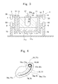
- FIG. 2 concerns Embodiment Mode No. 1, and is a diagram for schematically illustrating a state where pouring is done from the furnace body, which is present at the standby position, to a sprue of casting mold;
- FIG. 3 concerns Embodiment Mode No. 2, and is a conceptual diagram for schematically illustrating a furnace body, which is present at a standby position, from a different direction;
- FIG. 4 concerns Embodiment Mode No. 2, and is a conceptual diagram for schematically illustrating meshing between a pinion and racked teeth;
- FIG. 5 concerns Embodiment Mode No. 2, and is a diagram for schematically illustrating a cast-steel pouring apparatus that is present at a standby position;
- FIG. 6 concerns Embodiment Mode No. 2, and is a conceptual diagram for schematically illustrating a state where the cast-steel pouring apparatus is caused to pivot in a steel-outing direction in a pivotal previous period;
- FIG. 7 concerns Embodiment Mode No. 2, and is a conceptual diagram for schematically illustrating a state where steel outing is done from a furnace body of the cast-steel pouring apparatus to a sprue of casting mold in a pivotal later period;
- FIG. 8 concerns Embodiment Mode No. 3, and is a conceptual diagram for schematically illustrating a furnace body, which is present at a standby position, from a different direction;
- FIG. 9 concerns Embodiment Mode No. 3, and is a conceptual diagram for schematically illustrating the furnace body that is present at the standby position;
- FIG. 10 concerns Embodiment Mode No. 4, and is a conceptual diagram for schematically illustrating a furnace body that is present at a standby position;
- FIG. 11 concerns Embodiment Mode No. 4, and is a diagram for schematically illustrating a state where pouring is done from the furnace body, which is present at a casting position, to a sprue of casting mold;
- FIG. 12 concerns a comparative mode, and is a conceptual diagram for schematically illustrating a furnace body that is present at a standby position
- FIG. 13 concerns the comparative mode, and is a diagram for schematically illustrating a state where pouring is done from the furnace body, which is present at a casting position, to a sprue of casting mold.
- 1 specifies the cast-steel pouring apparatus
- 2 specifies the furnace body
- 20 specifies the retainer chamber
- 21 specifies the fire-retardant lining material
- 22 specifies the furnace-body main body
- 24 specifies the steel-outing trough unit
- 24 e specifies the steel-outing leading end
- 27 specifies the center line of the furnace body
- 28 specifies the outer-circumference wall face
- 29 specifies the inner-circumference wall face
- “P 2 ” specifies the second imaginary extension line
- 3 specifies the first pivot shaft
- 30 specifies the first axial line
- 4 specifies the first pivot driving source
- 5 specifies the second pivot shaft
- 50 specifies the second axial line
- 6 specifies the second pivot driving source
- 100 specifies the casting mold
- 101 specifies the sprue.
- a first axial line of a first pivot shaft is positioned on a more diametrically inner side than is a first imaginary extension line of an outer-circumference wall face in a furnace-body main body, and is positioned on a more diametrically outer side than is a second imaginary extension line of an inner-circumference wall face in a fire-retardant lining material that the furnace-body main body has.
- a steel-outing leading end of a steel-outing trough unit is positioned on a more diametrically inner side than is the first imaginary axial line of the outer-circumference wall face in the furnace-body main body, and is positioned on a more diametrically outer side than is the second imaginary extension line of the inner-circumference wall face in the fire-retardant lining material that the furnace-body main body has.
- the furnace body can comprise an induction heating coil, too, or cannot comprise it, either.
- a first pivot driving source and a second pivot driving source they can also be motor devices, or can even be fluidic-pressure cylinder devices as far as they are able to cause the furnace body to pivot.
- FIG. 1 and FIG. 2 illustrate concepts of Embodiment Mode No. 1 that concerns claims 1 and 2 according to the present invention.
- a cast-steel pouring apparatus 1 comprises a furnace body 2 being capable of functioning as a melting furnace that forms molten steel, a first pivot shaft 3 , a first pivot driving source 4 , a second pivot shaft 5 , and a second pivot driving source 6 .
- the furnace body 2 has a furnace-body main body 22 having a fire-retardant lining material 21 that demarcates a top-face-opened retainer chamber 20 for retaining molten steel of cast steel therein, and a steel-outing trough unit 24 protruding from the top end of the furnace-body main body 22 outward toward the upside obliquely.
- FIG. 1 illustrate concepts of Embodiment Mode No. 1 that concerns claims 1 and 2 according to the present invention.
- a cast-steel pouring apparatus 1 comprises a furnace body 2 being capable of functioning as a melting furnace that forms molten
- a shortest distance “LX” from the top end of the furnace-body main body 22 to a steel-outing leading end 24 e of the steel-outing trough unit 24 is set up to 2 ⁇ 3 or less of an inside diameter “DX” of the top-face opening in the retainer chamber 20 , or 1 ⁇ 2 or less thereof, or 1 ⁇ 3 or less thereof.
- a trough length of the steel-outing trough unit 24 is shortened, so that it is set up to 2 ⁇ 3 or less of the inside diameter “DX” of the top-face opening in the retainer chamber 20 , or 1 ⁇ 2 or less thereof, or 1 ⁇ 3 or less thereof.
- the fire-retardant lining material 21 and furnace-body main body 22 take on a bottomed cylindrical configuration, respectively.
- the furnace-body main body 22 has an induction heating coil 220 that is wound around the center line 27 .
- the steel-outing trough unit 24 comprises a steel-outing passage 25 for causing molten steel to discharge, and a concave-shaped portion 26 (see FIG. 1 ) that is disposed in a bottom wall face of the steel-outing passage 25 so as to be deeper than is the bottom wall face of the steel-outing passage 25 .
- the first pivot shaft 3 has a first axial line 30 that orients along the lateral direction (i.e., along the horizontal direction) in order to cause the furnace body 2 to pivot in the steel-outing direction (i.e., in one of the arrowheaded directions “A”) along the longitudinal direction.
- the first pivot shaft 3 is disposed on the upper side of the furnace body 2 , is disposed so as to be positioned above the height-wise position of the center of gravity “G” in the furnace body 2 , and is disposed adjacent to the steel-outing trough unit 24 in the height-wise direction (i.e., in the arrowheaded directions “H”).
- the first pivot driving source 4 causes the furnace body 2 to pivot in the steel-outing direction (i.e., in one of the arrowheaded directions “A”) about the first axial line 30 of the first pivot shaft 3 , which serves as the pivotal center, along the vertical direction, thereby causing some molten steel to discharge from the steel-outing trough unit 24 of the furnace body 2 , which has been caused to pivot, with respect to a sprue 101 of casting mold 100 .
- the first pivot driving source 4 is formed by a motor device.
- the casting mold 100 green-sand molds, shell-molding molds, and the like, can be exemplified.
- FIG. 1 illustrates a state where the furnace body 2 is put on standby so as to make the center line 27 of the furnace body 2 orient along the vertical direction.
- the steel-outing trough unit 24 protrudes from the top of the furnace body 2 upward and outward obliquely. Therefore, the extension line “SA” of the bottom face in the steel-outing passage 25 of the steel-outing trough unit 24 inclines by an angle “ ⁇ 1 ” with respect to the center line 27 of the furnace body 2 .
- the first axial line 30 of the first pivot shaft 3 is positioned on a more diametrically inner side than is a first imaginary extension line “P 1 ” of an outer-circumference wall face 28 in the furnace-body main body 22 , and is positioned on a more diametrically outer side than is a second imaginary extension line “P 2 ” of an inner-circumference wall face 29 in the fire-retardant material 21 of the furnace-body main body 22 , in the diametric direction (i.e., in the arrowheaded directions “D”) of the retainer chamber 20 , in accordance with the state where the furnace body 2 is put in place so that it is put on standby so as to make the center line 27 of the furnace body 2 orient along the vertical direction.
- a first imaginary extension line “P 1 ” of an outer-circumference wall face 28 in the furnace-body main body 22 is positioned on a more diametrically outer side than is a second imaginary extension line “P 2 ” of an inner-circumference wall face 29
- the steel-outing leading end 24 e of the steel-outing trough unit 24 is positioned on a more diametrically inner side than is the first imaginary extension line “P 1 ” of the outer-circumference wall face 28 in the furnace-body main body 22 , and is positioned on a more diametrically outer side than is the second imaginary extension line “P 2 ” of the inner-circumference wall face 29 in the fire-retardant material 21 of the furnace-body main body 22 , in the diametric direction (i.e., in the arrowheaded directions “D”), in the standby state where the furnace body 2 is put in place so as to make the center line 27 of the furnace body 2 orient along the vertical direction.
- the trough length of the steel-outing trough unit 24 is set up to be smaller, and accordingly is set up to be smaller than is the inside diameter “DX” of the top-face opening in the retainer chamber 20 .
- the second pivot shaft 5 has a second axial line 50 that orients along the lateral direction (i.e., along the horizontal direction) in order to cause the furnace body 2 to pivot along the longitudinal direction.
- the second pivot shaft 5 is disposed in the furnace-body main body 22 in order that the furnace body 22 is caused to pivot toward the steel-outing direction (i.e., in one of the arrowheaded directions “A”) without causing molten steel to discharge in a pivotal previous period.
- the second pivot driving source 6 causes the furnace body 2 to pivot about the second axial line 50 of the second pivot shaft 5 , which serves as the pivotal center, in the steel-outing direction (i.e., in one of the arrowheaded directions “A”).
- the second pivot driving source 6 can be formed by a motor device, or a motor device with deceleration mechanism.
- the furnace body 2 in which high-temperature molten steel of cast steel is retained in the retainer chamber 20 , is on standby (see FIG. 1 ).
- the molten steel forms cast-steel products, such as heat-resistance cast steels and stainless cast steels.
- the second pivot driving source 6 is driven at the time of casting in a state where high-temperature molten steel of cast steel is retained in the retainer chamber 20 of the furnace body 2 (see FIG. 1 ), and is driven at the pivotal previous period in another state where driving the first pivot driving source 4 is stopped.
- the furnace body 2 pivots about the second axial line 50 of the second pivot shaft 5 , which serves as the pivotal center, toward the steel-outing direction (i.e., in one of the arrowheaded directions “A”) along the longitudinal direction.
- the steel-outing direction i.e., in one of the arrowheaded directions “A”
- the furnace body 2 pivots about the second axial line 50 of the second pivot shaft 5 , which serves as the pivotal center, toward the steel-outing direction (i.e., in one of the arrowheaded directions “A”) along the longitudinal direction.
- the steel-outing trough unit 24 descends, about the second axial line 50 of the second pivot shaft 5 that serves as the pivotal center.
- the second pivot driving source 6 is driven to cause the furnace body 2 to pivot about the second axial line 50 of the second pivot shaft 5 , which serves as the pivotal center, in the steel-outing direction (i.e., in one of the arrowheaded directions “A”), while stopping driving the first pivot driving source 4 , at the time of steel outing in the pivotal previous period.
- driving the second pivot driving source 6 is caused to stop.
- the first pivot driving source 4 is driven to cause the furnace body 2 to pivot furthermore about the first axial line 30 of the first pivot shaft 3 , which serves as the pivotal center, in the steel-outing direction (i.e., in one of the arrowheaded directions “A”), in a state where driving the second pivot driving source 6 is caused to stop.
- molten steel which is retained in the retainer chamber 20 of the furnace body 2 , is caused to discharge from the leading end of the steel-outing trough unit 24 in the furnace body 2 .
- the discharged molten steel is received by the sprue 101 of the casting mold 100 .
- the casting mold 100 having the sprue 101 is disposed next to the furnace body 2 (see FIG. 2 ).
- the first pivot driving source 4 is driven to cause the furnace body 2 to pivot about the first axial line 30 of the first swing shaft 30 , which serves as the pivotal center, in the steel-outing direction (i.e., in one of the arrowheaded directions “A”) at the time of steel outing in the pivotal later period, thereby causing molten steel, which is retained in the retainer chamber 20 of the furnace body 2 , to discharge from the steel-outing leading end 24 e of the steel-outing trough unit 24 in the furnace body 2 in one of the arrowheaded directions “A 1 ” (i.e., in the discharging direction).
- a pivotal radius smaller within which the steel-outing leading end 24 e of the steel-outing trough unit 24 pivots because the furnace body 2 is caused to pivot, not about the second axial line 50 of the second pivot shaft 5 , but about the first axial line 30 , which serves as the pivotal center in the first pivot shaft 3 that is set up at a closer position to the steel-outing trough unit 24 than is the second pivot shaft 5 , in the steel-outing direction (i.e., in one of the arrowheaded directions “A”).
- the second pivot shaft 5 which orients along the lateral direction (i.e., along the horizontal direction) in which the furnace body 2 is caused to pivot along the longitudinal direction, is disposed in the furnace-body main body 22 .
- the second pivot shaft 5 has the second axial line 50 , but also it causes the furnace body 2 to pivot toward the steel-outing direction (i.e., in one of the arrowheaded directions “A”) without causing any molten steel in the retainer chamber 20 to discharge in the pivotal previous period.
- the first pivot driving source 4 can cause the molten steel in the retainer chamber 20 to discharge toward the sprue 101 of the casting mold 100 , as causing the furnace body 2 to pivot about the first axial line 30 of the first pivot shaft 3 , which serves as the pivotal center, in the pivotal later period.
- the second pivot driving source 6 is driven to cause the furnace body 2 to pivot, not about the first axial line 30 of the first pivot shaft 3 , but about the second axial line 50 of the second pivot shaft 5 (that is closer to the center of gravity “G” in the furnace body 2 than is the first axial line 30 of the first pivot shaft 3 ), second axial line 50 which serves as the center, in the steel-outing direction (i.e., in one of the arrowheaded directions “A”).
- the molten steel inside the retainer chamber 20 in the furnace body 2 is not caused to discharge toward the sprue 101 of the casting mold 100 .
- the first pivot driving source 4 causes the molten steel in the retainer chamber 20 to discharge toward the sprue 101 of the casting mold 100 in order to carry out casting, as causing the furnace body 2 to pivot about the first axial line 30 of the first pivot shaft 3 , which serves as the pivotal center, in the steel-outing direction (i.e., in one of the arrowheaded directions “A”).
- the second axial line 50 of the second pivot shaft 5 exists at a position that is closer with respect to the mass center of the furnace body 2 , which retains molten steel therein, than does the first pivot shaft 3 , as shown in FIG. 1 .
- the second pivot driving source 6 is first of all driven to cause the furnace body 2 to pivot about the second axial line 50 of the second pivot driving shaft 5 , which serves as the pivotal center, in the steel-outing direction (i.e., in one of the arrowheaded directions “A”) in the pivotal previous period.
- first pivot driving source 4 is driven to cause the furnace body 2 to pivot furthermore about the first axial line 30 of the first pivot driving shaft 3 , which serves as the pivotal center, toward the steel-outing direction (i.e., in one of the arrowheaded directions “A”).
- the increment of moment which is required for pivoting, as much as possible in the pivotal previous period, so that it is possible to keep down the weight loads, which apply to the first pivot driving source 4 and first pivot shaft 3 , as much as possible.
- FIG. 12 and FIG. 13 illustrate a cast-steel casting apparatus that concerns a comparative mode.
- This apparatus is equipped with: a furnace body 2 having a furnace-body main body 22 , which has a retainer chamber 20 for retaining molten steel of cast steel therein, and a steel-outing trough unit 24 protruding from the furnace-body main body 22 toward the upside outwardly; a first pivot shaft 3 orienting along a lateral direction in which the furnace body 2 is caused to pivot along a longitudinal direction; a first pivot driving source (not shown) for causing the furnace body 2 to pivot about the first pivot shaft 3 , which serves as a pivotal center, along the longitudinal direction, thereby causing the molten steel to discharge from the steel-outing trough unit 24 of the furnace body 2 , which has been caused to pivot, with respect to a sprue 101 of casting mold 100 ; a second pivot shaft 5 orienting along the lateral direction in which the furnace body 2 is caused to pivot along the longitudinal direction;
- the steel-outing trough unit 4 is disposed to extend on the upper side obliquely in a standby state (see FIG. 12 ) where the furnace body 2 is put in place so that the center line 27 of the furnace body 2 orients along the vertical direction.
- a steel-outing leading end 24 e of the steel-outing trough unit 24 is positioned on an outer side by a dimension “D 10 ” in the horizontal direction than is a first imaginary extension line “P 1 ” of the outer-circumference wall face 28 in the furnace-body main body 22 . Consequently, in the comparative mode, a length of the steel-outing trough unit 24 is longer. Specifically, a distance “r 5 ” (see FIG.
- FIG. 3 through FIG. 7 illustrate concepts of Embodiment Mode No. 2 schematically. Since the present embodiment mode comprises the same constructions, as well as the same operations and advantageous effects, as those of Embodiment Mode No. 1 fundamentally, it is possible to use FIG. 1 and FIG. 2 compliantly.
- the first axial line 30 of the first pivot shaft 3 is positioned on a more diametrically inner side than is the first imaginary extension line “P 1 ” of the outer-circumference wall face 28 in the furnace-body main body 22 in the diametric direction of the furnace-body main body 22 , and is positioned on a more diametrically outer side than is the second imaginary extension line “P 2 ” of the inner-circumference wall face 29 of the fire-retardant lining material 21 in the furnace-body main body 22 .
- the first pivot shaft 3 has the first axial line 30 that orients in the lateral direction (i.e., in the horizontal direction) in order to cause the furnace body 2 to pivot in the steel-outing direction (i.e., in one of the arrowheaded directions “A”) along the longitudinal direction.
- the second pivot shaft 5 has the second axial line 50 that orients in the lateral direction (i.e., in the horizontal direction) in order to cause the furnace body 2 to pivot in the steel-outing direction (i.e., in one of the arrowheaded directions “A”) along the longitudinal direction. As illustrated in FIG. 1 and FIG.
- the steel-outing leading end 24 e of the steel-outing trough unit 24 is positioned on a diametrically inner side than is the first imaginary extension line “P 1 ” of the outer-circumference wall face 28 in the furnace-body main body 22 , and is positioned on a diametrically outer side than is the second imaginary extension line “P 2 ” of the inner-circumference wall face 29 of the fire-retardant lining material 21 in the furnace-body main body 22 .
- the cast-steel pouring apparatus 1 comprises a fixation unit 70 being installed onto an installation face, an inner frame 71 retaining the furnace body 2 integrally, an outer frame 72 retaining the inner frame 71 integrally, the first pivot driving source 4 , and the second pivot driving source 6 , as shown in FIG. 3 .
- the fixation unit 70 is disposed on both sides of the furnace body 2 .
- the outer frame 72 comprises a bottom 72 v , and is supported pivotably onto the fixation unit 70 by way of the second pivot shaft 5 in the steel-outing direction (i.e., in the arrowheaded direction “A”).
- the outer frame 72 pivots about the second axial line 50 of the second pivot shaft 5 , which serves as the pivotal center, in the steel-outing direction (i.e., in the arrowheaded direction “A”), as shown in FIG. 6 .
- the inner frame 71 comprises a bottom 71 v , and is supported onto the outer frame 72 pivotably about the first axial line 30 of the first pivot shaft 3 , which serves as the pivotal center, in the steel-outing direction (i.e., in one of the arrowheaded directions “A”), as retaining the furnace body 2 .
- the first pivot driving source 4 is formed by a motor device, or a motor device with deceleration mechanism, and is fixed onto the outer frame 72 , thereby causing a first pinion gear 43 to rotate around a gear center line 43 c thereof.
- the second pivot driving source 6 is formed by a motor device, or a motor device with deceleration mechanism, and is fixed onto the fixation unit 70 , thereby causing a second pinion gear 63 to rotate around the gear center line 63 c . Note that, when the first pivot driving source 4 is driven, the first pinion gear 43 rotates about the gear center line 43 c thereof, which serves as the center, byway of a not-shown transmission mechanism. When the second pivot driving source 6 is driven, the second pinion gear 63 rotates about the gear center line 63 c thereof, which serves as the center, by way of a not-shown transmission mechanism.
- FIG. 5 illustrates a standby state where the furnace body 2 is put in place so as to make the center line 27 of the furnace body 2 orient along the vertical direction.
- the second pivot shaft 5 is put in place on a lower side than is the first pivot shaft 3 .
- a second pivot body 75 is fixed onto one of the lateral sides of the outer frame 72 .
- the second pivot body 75 has sides ( 75 a , 75 b , 75 c ).
- the second pivot body 75 further has a second guide groove 77 that is disposed to extend as an arc shape along a pivotal locus in which the second pivot shaft 5 serves as the center.
- a first pivot body 74 is fixed onto one of the lateral sides of the inner frame 71 , as shown in FIG. 5 .
- the first pivot body 74 is positioned on an upper side to the second pivot body 75 , and has sides ( 74 a , 74 b , 74 c ).
- the first pivot body 74 further has a first guide groove 76 that is disposed to extend as an arc shape along a pivotal locus in which the first pivot shaft 3 serves as the center.
- racked teeth 78 with which the first pinion gear 43 meshes as it rotates, are formed on an edge wall 76 w on an outer-circumference side in the first guide groove 76 , as shown in FIG. 4 .
- racked teeth 78 On an edge wall 77 w on an outer-circumference side among the second guide groove 77 , racked teeth 78 , with which the second pinion gear 63 meshes as it rotates, are formed.
- FIG. 4 On an edge wall 77 w on an outer-circumference side among the second guide groove 77 , racked teeth 78 , with which the second pinion gear 63 meshes as it rotates, are formed.
- the racked teeth 78 are formed on the edge walls ( 76 w , 77 w ) on the outer-circumference side among the guide grooves ( 76 , 77 ), it is possible to enhance the retaining property for the pinion gears ( 43 , 63 ), so that it is possible to contribute to securing the power-transmitting property.
- the furnace body 2 is on standby so that the center line 27 of the furnace body 2 orients along the vertical direction, as shown in FIG. 5 . It is also allowable that the induction heating coil 220 can be subjected to power feeding so that the molten steel in the retainer chamber 20 is heated, or it is even permissible that the molten steel cannot be heated.
- the second pinion gear 63 is positioned at the upper-side starting end 77 i in the second guide groove 77 , as shown in FIG. 5 , as meshing with the racked teeth 78 of the second guide groove 77 .
- the first pinion gear 43 is positioned at the upper-side starting end 76 i in the first guide groove 76 , as meshing with the racked teeth 78 of the first guide groove 76 .
- the cast-steel pouring apparatus 1 shifts from this standby state to a pivotal previous period.
- the lower-side second pivot driving source 6 is first of all driven rotationally in order to cause the second pinion gear 63 to rotate around the gear center line 63 c thereof, in a state where driving the upper-side first pivot driving source 4 is caused to stop.
- the second pinion gear 63 rotates about the gear center line 63 c , as meshing with the second racked teeth 78 of the second guide groove 77 , in a state where the second pinion gear 63 is retained at its height position.
- the lower-side second pivot body 75 pivots to the upper side about the second axial line 50 of the lower-side second pivot shaft 5 , which serves as the pivotal center, toward the steel-outing direction (i.e., in the arrowheaded direction “A”) (see FIG. 6 ).
- the second pinion gear 63 rotates around the gear center line 63 c , as it meshes with the racked teeth 78 , in a state where it is maintained at a predetermined position, the second guide groove 77 and second pivot body 75 rotates integrally to the upper side toward the steel-outing direction (i.e., in the arrowheaded direction “A”) (see FIG. 6 ). Since the second pivot body 75 is thus pushed up, the terminal end 77 e in the guide groove 77 of the second pivot body 75 reaches the second pinion gear 63 (see FIG. 6 ).
- the second pivot body 75 pivots about the second axial line 50 of the second pivot shaft 5 , which serves as the pivotal center, in the steel-outing direction (i.e., in the arrowheaded direction “A”), as being shown in FIG. 6 .
- the outer frame 72 which retains the second pivot body 75 integrally, pivots in the same direction, too.
- the first pinion gear 43 is put in a state where it is kept being positioned at the starting end 77 i in the first guide groove 76 , as shown in FIG. 6 , because the first pivot driving source 4 is not driven rotationally, although the second pivot driving source 6 is driven rotationally.
- the cast-steel pouring apparatus 1 shifts from the pivotal previous period to the pivotal later period. That is, in a state where driving the second pivot driving source 6 is caused to stop, the first pivot driving source 4 is caused to be driven rotationally. As a result, the first pinion gear 43 rotates about the gear center 43 c thereof, as meshing with the racked teeth 78 of the first guide groove 76 .
- the first pivot body 74 having the first guide groove 76 pivots furthermore toward the upper side about the first axial line 30 of the first pivot shaft 3 , which serves as the pivotal center, in the steel-outing direction (i.e., in the arrowheaded direction “A”), as shown in FIG. 7 . Consequently, the terminal end 76 e in the first guide groove 76 reaches the first pinion gear 43 (see FIG. 7 ).
- the inner frame 71 having the first pivot body 74 along with the furnace body 2 being retained in the inner frame 71 , pivots about the first axial line 30 of the first pivot shaft 3 , which serves as the pivotal center, in the steel-outing direction (i.e., in the arrowheaded direction “A”), as shown in FIG. 7 .
- the outer frame 72 retaining the second pivot body 75 therein is kept being stopped at the pivotal position at the terminal time point in the pivotal previous period (see FIG. 7 ), because rotationally driving the second pivot driving source 6 is caused to stop.
- the driving forces of the pivot driving sources ( 4 , 6 ) are input into the pinion gears ( 43 , 63 ), respectively.
- a distance “r 1 ” between the gear center line 43 c of the pinion gear 43 and the first axial line 30 of the first pivot shaft 3 is secured.
- another distance “r 2 ” between the gear center line 63 c of the pinion gear 63 and the second axial line 50 of the second pivot shaft 5 is secured. Since the distances (r 1 , r 2 ) are thus secured, it is possible to increase pivotal moments.
- a dented retraction portion 2 x is formed in a region among the furnace body 2 that faces to the casting mold 100 .
- the retraction portion 2 x inclines with respect to the center line 27 of the furnace body 2 .
- the furnace body 2 i.e., the retraction portion 2 x
- the furnace body 2 is suppressed from interfering with the casting mold 100 even when subjecting the furnace body 2 to steel outing by causing it to pivot as letting it approach the casting mold 100 . Therefore, it is advantageous for doing steel outing as causing the furnace body 2 to approach the casting mold 100 .
- FIG. 8 and FIG. 9 illustrate concepts of Embodiment Mode No. 3 schematically. Since the present embodiment mode comprises the same constructions, as well as the same operations and advantageous effects, as those of Embodiment Mode Nos. 1 and 2 fundamentally, FIG. 1 and FIG. 2 are used compliantly. As can be understood from FIG. 1 and FIG.
- the first axial line 30 of the first pivot shaft 3 is positioned on a more diametrically inner side than is the first imaginary extension line “P 1 ” of the outer-circumference wall face 28 in the furnace-body main body 22 in the diametric direction of the furnace-body main body 22 (i.e., in the arrowheaded directions “D”), and is positioned on a more diametrically outer side than is the second imaginary extension line “P 2 ” of the inner-circumference wall face 29 of the fire-retardant lining material 21 in the furnace-body main body 22 .
- the steel-outing leading end 24 e of the steel-outing trough unit 24 is positioned on a diametrically inner side than is the first imaginary extension line “P 1 ” of the outer-circumference wall face 28 in the furnace-body main body 22 , and is positioned on a diametrically outer side than is the second imaginary extension line “P 2 ” of the inner-circumference wall face 29 of the fire-retardant lining material 21 in the furnace-body main body 22 .
- the first pivot driving source 4 is disposed so as to be positioned on an outer side of the furnace body 2 and outer frame 72 , as can be understood from FIG. 8 and FIG. 9 .
- the second pivot driving source 6 is disposed so as to be positioned on an outer side of the furnace body 2 and outer frame 72 .
- the first pivot driving source 4 and second pivot driving source 6 are formed by a motor device with deceleration mechanism, respectively.
- the first pivot driving source 4 is disposed coaxially therewith.
- the second pivot driving source 6 is disposed coaxially therewith. Consequently, structures for transmitting the driving forces are simplified.
- FIG. 9 illustrates a state where the furnace body 2 is on standby so that the center line 27 of the furnace body 2 orients along the vertical direction.
- the cast-steel pouring apparatus 1 pivots from this standby state.
- the second pivot driving source 6 is first of all driven rotationally in order to put the cast-steel pouring apparatus 1 in the pivotal previous period, in a state where driving the first pivot driving source 4 is caused to stop.
- the cast-steel pouring apparatus 1 shifts from the pivotal previous period to a pivotal later period. That is, in a state where rotationally driving the second pivot driving source 6 is caused to stop, the first pivot driving source 4 is driven rotationally.
- FIG. 10 and FIG. 11 illustrate Embodiment Mode No. 4.
- the present embodiment mode comprises the same constructions, as well as the same operations and advantageous effects, as those of Embodiment Mode Nos. 1 and 2 fundamentally.
- the present embodiment mode is suitable for a case where the volume of the retainer chamber 20 is small.
- the steel-outing trough unit 24 protrudes from the top portion of the furnace body 2 to the upside and outside obliquely, in FIG. 10 that illustrates the standby position.
- the first axial line 30 of the first pivot shaft 3 is positioned on a more diametrically inner side than is the first imaginary extension line “P 1 ” of the outer-circumference wall face 28 in the furnace-body main body 22 , and is positioned on a more diametrically outer side than is the second imaginary extension line “P 2 ” of the inner-circumference wall face 29 of the fire-retardant lining material 21 in the furnace-body main body 22 .
- the steel-outing leading end 24 e of the steel-outing trough unit 24 is positioned on a diametrically inner side than is the first imaginary extension line “P 1 ” of the outer-circumference wall face 28 in the furnace-body main body 22 , and is positioned on a diametrically outer side than is the second imaginary extension line “P 2 ” of the inner-circumference wall face 29 of the fire-retardant lining material 21 in the furnace-body main body 22 , in the diametric direction, according to FIG. 10 that illustrates the standby position.
- the second pivotal shaft 5 and second pivot driving source 6 are not loaded thereonto at all. Therefore, the execution is done from the standby position to the casting position by means of rotationally driving the first pivot driving.
- the furnace body 2 is a ladle having the retainer chamber 20 that retains molten steel therein.
- the furnace body 2 does not comprise any function of actively heating the molten steel in the retainer chamber 20 , because it does not comprise any induction heating coil.
- the present invention is not one which is limited to the embodiment modes alone that are mentioned above and are illustrated in the drawings, but can be executed by properly making alterations thereto within a scope that does not deviates from the gist. It is also allowable that the fixation unit 70 can be fixed onto the installation face, or it is even allowable that the fixation unit 70 can be a movable-type fixation unit being conveyed along the installation face.
Abstract
Description
-
- a fixation unit;
- an outer frame being supported onto the fixation unit pivotably about the second pivot shaft, which serves as the pivotal center, in the steel-outing direction; and
- an inner frame retaining the furnace body therein, the inner frame being supported onto the outer frame pivotably about the first pivot shaft, which serves as the pivotal center, in the steel-outing direction.
In the pivotal previous period, the outer frame pivots about the second pivot shaft, which serves as the pivotal center, in the steel-outing direction. Next, in the pivotal later period, along with the furnace body, the inner frame pivots about the first pivot shaft, which serves as the pivotal center, in the steel-outing direction. In this way, the molten steel, which is retained in the retainer chamber of the furnace body, is poured into the sprue of casting mold.
Claims (8)
Applications Claiming Priority (3)
| Application Number | Priority Date | Filing Date | Title |
|---|---|---|---|
| JP2011072543A JP5492129B2 (en) | 2011-03-29 | 2011-03-29 | Cast steel pouring equipment |
| JP2011-072543 | 2011-03-29 | ||
| PCT/JP2012/001174 WO2012132209A1 (en) | 2011-03-29 | 2012-02-22 | Steel casting pouring apparatus |
Publications (2)
| Publication Number | Publication Date |
|---|---|
| US20140015174A1 US20140015174A1 (en) | 2014-01-16 |
| US9095897B2 true US9095897B2 (en) | 2015-08-04 |
Family
ID=46930005
Family Applications (1)
| Application Number | Title | Priority Date | Filing Date |
|---|---|---|---|
| US13/985,696 Expired - Fee Related US9095897B2 (en) | 2011-03-29 | 2012-02-22 | Cast-steel pouring apparatus |
Country Status (4)
| Country | Link |
|---|---|
| US (1) | US9095897B2 (en) |
| JP (1) | JP5492129B2 (en) |
| CN (1) | CN103338878B (en) |
| WO (1) | WO2012132209A1 (en) |
Families Citing this family (5)
| Publication number | Priority date | Publication date | Assignee | Title |
|---|---|---|---|---|
| JP5492129B2 (en) * | 2011-03-29 | 2014-05-14 | アイシン高丘株式会社 | Cast steel pouring equipment |
| JP6083521B2 (en) * | 2013-04-16 | 2017-02-22 | 国立大学法人富山大学 | Method for producing Al-Li alloy |
| JP2018501175A (en) * | 2014-10-31 | 2018-01-18 | コーニング インコーポレイテッド | Laser welded glass package and manufacturing method thereof |
| JP6995709B2 (en) | 2018-07-06 | 2022-01-17 | 新東工業株式会社 | Cast steel casting manufacturing system |
| CN109175340A (en) * | 2018-11-08 | 2019-01-11 | 山东杰创机械有限公司 | A kind of casting positioning casting ladle |
Citations (9)
| Publication number | Priority date | Publication date | Assignee | Title |
|---|---|---|---|---|
| US3531074A (en) * | 1968-03-18 | 1970-09-29 | Inductotherm Corp | Tilting and supporting apparatus for foundry vessels |
| US3751854A (en) * | 1971-02-05 | 1973-08-14 | Bbc Brown Boveri & Cie | Cover lifting-and swinging mechanism for a tiltable furnace |
| JPS5887099A (en) | 1981-11-17 | 1983-05-24 | 株式会社ト−カイ | Measure type rule for base line |
| JPH07112270A (en) | 1993-10-18 | 1995-05-02 | Towa Kiko Kk | Method and device for automatically pouring molten metal |
| JPH0825024A (en) | 1994-07-15 | 1996-01-30 | Asahi Tec Corp | Casting device |
| JPH09168858A (en) | 1995-12-18 | 1997-06-30 | Asahi Kiko Kk | Method for pouring molten metal into ladle and device therefor |
| WO2008099556A1 (en) | 2007-02-15 | 2008-08-21 | Sintokogio, Ltd. | Automatic pouring method and device |
| JP2012011443A (en) | 2010-07-05 | 2012-01-19 | Sintokogio Ltd | Tilting type molten metal pouring apparatus |
| US20140015174A1 (en) * | 2011-03-29 | 2014-01-16 | Aisin Takaoka Co., Ltd. | Cast-steel pouring apparatus |
Family Cites Families (3)
| Publication number | Priority date | Publication date | Assignee | Title |
|---|---|---|---|---|
| JPS5887099U (en) * | 1981-12-07 | 1983-06-13 | 北芝電機株式会社 | Crucible induction melting furnace |
| EP0996517B1 (en) * | 1997-06-27 | 2001-04-18 | Hubo Engineering GmbH | Method and device for controlling the movement of a teeming ladle having a low teeming height in a teeming installation |
| CN201030433Y (en) * | 2007-05-25 | 2008-03-05 | 昆明理工大学 | Sprue gate fixed-axis rotation type molten metal pouring device |
-
2011
- 2011-03-29 JP JP2011072543A patent/JP5492129B2/en not_active Expired - Fee Related
-
2012
- 2012-02-22 CN CN201280004279.XA patent/CN103338878B/en not_active Expired - Fee Related
- 2012-02-22 WO PCT/JP2012/001174 patent/WO2012132209A1/en active Application Filing
- 2012-02-22 US US13/985,696 patent/US9095897B2/en not_active Expired - Fee Related
Patent Citations (10)
| Publication number | Priority date | Publication date | Assignee | Title |
|---|---|---|---|---|
| US3531074A (en) * | 1968-03-18 | 1970-09-29 | Inductotherm Corp | Tilting and supporting apparatus for foundry vessels |
| US3751854A (en) * | 1971-02-05 | 1973-08-14 | Bbc Brown Boveri & Cie | Cover lifting-and swinging mechanism for a tiltable furnace |
| JPS5887099A (en) | 1981-11-17 | 1983-05-24 | 株式会社ト−カイ | Measure type rule for base line |
| JPH07112270A (en) | 1993-10-18 | 1995-05-02 | Towa Kiko Kk | Method and device for automatically pouring molten metal |
| JPH0825024A (en) | 1994-07-15 | 1996-01-30 | Asahi Tec Corp | Casting device |
| JPH09168858A (en) | 1995-12-18 | 1997-06-30 | Asahi Kiko Kk | Method for pouring molten metal into ladle and device therefor |
| WO2008099556A1 (en) | 2007-02-15 | 2008-08-21 | Sintokogio, Ltd. | Automatic pouring method and device |
| JP2010519041A (en) | 2007-02-15 | 2010-06-03 | 新東工業株式会社 | Automatic pouring method and automatic pouring device |
| JP2012011443A (en) | 2010-07-05 | 2012-01-19 | Sintokogio Ltd | Tilting type molten metal pouring apparatus |
| US20140015174A1 (en) * | 2011-03-29 | 2014-01-16 | Aisin Takaoka Co., Ltd. | Cast-steel pouring apparatus |
Non-Patent Citations (2)
| Title |
|---|
| English Language Machine translation of JP 2012-11443, Jan. 2012. * |
| Notification of Reasons for Refusal issued by the Japanese Patent Office on Nov. 19, 2013. |
Also Published As
| Publication number | Publication date |
|---|---|
| CN103338878B (en) | 2015-01-07 |
| WO2012132209A1 (en) | 2012-10-04 |
| CN103338878A (en) | 2013-10-02 |
| US20140015174A1 (en) | 2014-01-16 |
| JP2012206134A (en) | 2012-10-25 |
| JP5492129B2 (en) | 2014-05-14 |
Similar Documents
| Publication | Publication Date | Title |
|---|---|---|
| US9095897B2 (en) | Cast-steel pouring apparatus | |
| CN101607308B (en) | Ladle for molten metal | |
| US10086430B2 (en) | Method for producing iron metal castings | |
| US9182173B2 (en) | Arc furnace | |
| US7770628B2 (en) | Control of casting machine | |
| KR20120007432A (en) | Treatment ladle | |
| JPWO2013132790A1 (en) | Hot metal ladle transport device and hot ladle transport method | |
| US5817164A (en) | Method and apparatus for making feedstock for steel making | |
| JP2010172914A (en) | Partition cold material and continuous casting method | |
| KR101461573B1 (en) | Cover and covering device | |
| KR102605727B1 (en) | Hybrid ladle and automatic molten metal injection system using hybrid ladle and molten metal injection method of automatic molten metal injection system using hybrid ladle | |
| JP2000001711A (en) | Desulfurization of molten iron and desulfurizing device | |
| JP7180495B2 (en) | Water heater and hot water supply method | |
| JP2006122992A (en) | Semi-solid casting device | |
| CN212832720U (en) | Play to rise device of chute heat preservation lid | |
| EP1334324B1 (en) | Melting furnace for metal leagues fit to the direct and continuous poured of the melted metal | |
| KR20100008519U (en) | Material putting apparatus for centrifugal casting | |
| JP6156271B2 (en) | Thermal insulation lid for ladle | |
| JP2008221309A (en) | Method for manufacturing cylindrical body | |
| JPS5832141Y2 (en) | Refractory lining equipment for molten metal containers | |
| JP2012011443A (en) | Tilting type molten metal pouring apparatus | |
| KR101545980B1 (en) | Nozzle apparatus and continuous casting apparatus including the same | |
| CN114749647A (en) | Ladle capping device and ladle capping method | |
| JPH09276996A (en) | Method for preventing surface oxidation (deckel) at the time of starting reused tundish | |
| CN116921638A (en) | Molten iron granulating method |
Legal Events
| Date | Code | Title | Description |
|---|---|---|---|
| AS | Assignment |
Owner name: AISIN TAKAOKA CO., LTD., JAPAN Free format text: ASSIGNMENT OF ASSIGNORS INTEREST;ASSIGNORS:SATO, TAKAHIRO;CYOMATSUKEN, SHINICHI;ZHANG, ZHONG-ZHI;AND OTHERS;REEL/FRAME:031018/0406 Effective date: 20130612 Owner name: FUJIWA DENKI CO., LTD., JAPAN Free format text: ASSIGNMENT OF ASSIGNORS INTEREST;ASSIGNORS:SATO, TAKAHIRO;CYOMATSUKEN, SHINICHI;ZHANG, ZHONG-ZHI;AND OTHERS;REEL/FRAME:031018/0406 Effective date: 20130612 Owner name: SINTOKOGIO, LTD., JAPAN Free format text: ASSIGNMENT OF ASSIGNORS INTEREST;ASSIGNORS:SATO, TAKAHIRO;CYOMATSUKEN, SHINICHI;ZHANG, ZHONG-ZHI;AND OTHERS;REEL/FRAME:031018/0406 Effective date: 20130612 |
|
| STCF | Information on status: patent grant |
Free format text: PATENTED CASE |
|
| FEPP | Fee payment procedure |
Free format text: PAYOR NUMBER ASSIGNED (ORIGINAL EVENT CODE: ASPN); ENTITY STATUS OF PATENT OWNER: LARGE ENTITY |
|
| MAFP | Maintenance fee payment |
Free format text: PAYMENT OF MAINTENANCE FEE, 4TH YEAR, LARGE ENTITY (ORIGINAL EVENT CODE: M1551); ENTITY STATUS OF PATENT OWNER: LARGE ENTITY Year of fee payment: 4 |
|
| FEPP | Fee payment procedure |
Free format text: MAINTENANCE FEE REMINDER MAILED (ORIGINAL EVENT CODE: REM.); ENTITY STATUS OF PATENT OWNER: LARGE ENTITY |
|
| LAPS | Lapse for failure to pay maintenance fees |
Free format text: PATENT EXPIRED FOR FAILURE TO PAY MAINTENANCE FEES (ORIGINAL EVENT CODE: EXP.); ENTITY STATUS OF PATENT OWNER: LARGE ENTITY |
|
| STCH | Information on status: patent discontinuation |
Free format text: PATENT EXPIRED DUE TO NONPAYMENT OF MAINTENANCE FEES UNDER 37 CFR 1.362 |
|
| FP | Lapsed due to failure to pay maintenance fee |
Effective date: 20230804 |