US9091663B2 - Device for determining the wear of a carbon ceramic brake disk - Google Patents
Device for determining the wear of a carbon ceramic brake disk Download PDFInfo
- Publication number
- US9091663B2 US9091663B2 US13/546,640 US201213546640A US9091663B2 US 9091663 B2 US9091663 B2 US 9091663B2 US 201213546640 A US201213546640 A US 201213546640A US 9091663 B2 US9091663 B2 US 9091663B2
- Authority
- US
- United States
- Prior art keywords
- coils
- brake disk
- structured
- centers
- measuring
- Prior art date
- Legal status (The legal status is an assumption and is not a legal conclusion. Google has not performed a legal analysis and makes no representation as to the accuracy of the status listed.)
- Active, expires
Links
Images


Classifications
-
- G—PHYSICS
- G01—MEASURING; TESTING
- G01N—INVESTIGATING OR ANALYSING MATERIALS BY DETERMINING THEIR CHEMICAL OR PHYSICAL PROPERTIES
- G01N27/00—Investigating or analysing materials by the use of electric, electrochemical, or magnetic means
- G01N27/72—Investigating or analysing materials by the use of electric, electrochemical, or magnetic means by investigating magnetic variables
- G01N27/82—Investigating or analysing materials by the use of electric, electrochemical, or magnetic means by investigating magnetic variables for investigating the presence of flaws
- G01N27/90—Investigating or analysing materials by the use of electric, electrochemical, or magnetic means by investigating magnetic variables for investigating the presence of flaws using eddy currents
- G01N27/9006—Details, e.g. in the structure or functioning of sensors
-
- G01N27/9033—
-
- F—MECHANICAL ENGINEERING; LIGHTING; HEATING; WEAPONS; BLASTING
- F16—ENGINEERING ELEMENTS AND UNITS; GENERAL MEASURES FOR PRODUCING AND MAINTAINING EFFECTIVE FUNCTIONING OF MACHINES OR INSTALLATIONS; THERMAL INSULATION IN GENERAL
- F16D—COUPLINGS FOR TRANSMITTING ROTATION; CLUTCHES; BRAKES
- F16D66/00—Arrangements for monitoring working conditions, e.g. wear, temperature
- F16D66/02—Apparatus for indicating wear
- F16D66/021—Apparatus for indicating wear using electrical detection or indication means
-
- G—PHYSICS
- G01—MEASURING; TESTING
- G01N—INVESTIGATING OR ANALYSING MATERIALS BY DETERMINING THEIR CHEMICAL OR PHYSICAL PROPERTIES
- G01N27/00—Investigating or analysing materials by the use of electric, electrochemical, or magnetic means
- G01N27/72—Investigating or analysing materials by the use of electric, electrochemical, or magnetic means by investigating magnetic variables
- G01N27/80—Investigating or analysing materials by the use of electric, electrochemical, or magnetic means by investigating magnetic variables for investigating mechanical hardness, e.g. by investigating saturation or remanence of ferromagnetic material
Definitions
- Embodiments of the invention relates to a device for determining the wear of a carbon ceramic brake disk.
- the device includes at least one coil for generating a magnetic field in the brake disk and for detecting an eddy current in the brake disk.
- a “carbon ceramic brake disk” is a brake disk comprising a carbon ceramic, wherein the carbon ceramic comprises a ceramic matrix as well as carbon fibers embedded in the matrix.
- the by far largest problem of such procedures lies in the fact that, due to the unavoidable inhomogeneity of the material, the measured values can differ strongly as a function of location (variations up to 100% are observed). A further variation is caused by the venting ducts extending within the disk.
- a conventional device can, upon a dislocation of a few millimeters, display a value that deviates by more than 10%. Since the drop of the measured value between a new and a worn disk is at approximately 40 to 50%, such a location dependence is greatly disadvantageous for a measurement.
- a further disturbing factor is due to the metallic elements, such as the caliper, axle shaft and fender, present around a built-in brake disk.
- embodiments of the invention are directed to a device of the type mentioned above that allows a more reliable measurement of the wear.
- the device for determining wear in a carbon ceramic brake disk includes a coil arrangement having at least one coil adapted and structured to generate a magnetic field in the brake disk and for detecting an eddy current in the brake disk.
- the coil arrangement has an arcuate measuring area.
- the “measuring area” is the area in a measuring plane (i.e., in a plane parallel to the plane of the coils) that is reached by the field of the coil or coils during the measurement.
- the measuring area includes those locations in the measuring plane where the flux of the magnetic field generated by the coil(s) is at least 50% of a maximum value of the flux of the magnetic field in the measuring plane.
- a non-local measurement can be carried out over an extended region of the brake disk, which makes the measurement less sensitive to local inhomogeneities of the carbon ceramic.
- the coil arrangement comprises at least three coils, in particular more than three coils, as well as a drive for generating, by means of the coils, a magnetic field in the measuring area.
- Embodiments of the invention are directed to a device for determining wear in a carbon ceramic brake disk.
- the device includes a coil arrangement having at least one coil structured and arranged to generate a magnetic field in the brake disk and to detect an eddy current in the brake disk, and an arcuate measuring area.
- the arcuate measuring area may be positionable in a ring having a radial width smaller than 2 cm and an inner radius between 10 and 15 cm, and a length tangentially along the ring of at least 8 cm.
- the at least one coil can include at least three coils structured and arranged to generate a magnetic field in the measuring area.
- the at least one coil may include more than three coils structured and arranged to generate a magnetic field in the measuring area.
- the device can also include a common carrier plate on which the coils.
- the coils can be formed by conductive leads on the carrier plate.
- each coil can extend around a center and the centers of the coils may be arranged on an arcuate curve.
- the centers of the coils can be arranged on a segment of a circle.
- each coil may extend around a center and the centers of the coils may be arranged on at least two arcuate, parallel curves.
- the centers of the coils can be arranged on at least two segments of concentric circles.
- the device may also include a common carrier plate on which the coils are arranged, and the common carrier plate one of forming a measuring surface or abutting on an inner side of a wall section forming the measuring surface. Further, each two neighboring coils on different curves can be poled anti-parallel to each other.
- the device may further include a voltage supply and a driver.
- the driver can be structured and arranged to connect the coils, in parallel to each other, to the voltage supply.
- the driver can be structured and arranged to disconnect the coils from the voltage supply and to sum inductive voltages generated over the coils after disconnecting the coils from the voltage supply.
- mutually neighboring coils can be poled anti-parallel to each other.
- the device may also include a housing and stops arranged on the housing being structured and arranged to radially abut against the brake disk.
- the device can also include a measuring surface structured and arranged to abut against a front side of the brake disk.
- the stops can include projections extending transversally to the measuring surface.
- the projections may include rollers.
- the device can also include a light source for generating a light field as a positioning aid. The light source and the stops can be mutually arranged to generate a light strip on a front face of the brake disk upon abutting the device against the brake disk.
- the device can also include a light source structured and arranged to generate a light field as a positioning aid.
- a diameter of the at least one coil can be between 10 and 15 mm.
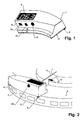
- FIG. 1 shows a first perspective view of the device
- FIG. 2 shows a view of the device abutting against a brake disk
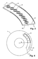
- FIG. 3 shows a representation of the arrangement of the measuring coils
- FIG. 4 is a schematic representation of the measuring area on the brake disk
- FIG. 5 shows a measured value as a function of the angle
- FIG. 6 is a partial block circuit diagram of the device.
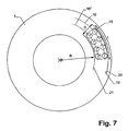
- FIG. 7 shows a device with two rows of measuring coils.
- the device illustrated in FIGS. 1 and 2 include a housing 1 with a measuring surface 2 intended to abut against a front face 3 of brake disk 4 during the measurement. Further, stops 5 , 6 are provided on housing 1 to extend transversally, in particular, perpendicularly, to measuring surface 2 . Stops 5 , 6 are arranged to radially abut housing 1 against an outer edge 7 of brake disk 4 , i.e., they are used to radially align housing 1 with respect to brake disk 4 . Stops 5 , 6 are designed as projections that extend over measuring surface 2 . Advantageously, exactly two such projections are employed in order to ensure a defined radial abutment on brake disk 4 .
- the device further includes a display 8 , advantageously arranged on a side of housing 1 that is opposite to measuring surface 2 so that it can be seen by the user.
- a side 9 of housing 1 is arranged to face the axle of brake disk 4 .
- side 9 includes a light source 11 , which can include, e.g., a semiconductor laser having a light beam is extended in a direction perpendicular to front face 3 to form a planar light field 12 .
- Planar light field 12 can serve as a positioning help because light source 11 and stops 5 , 6 should preferably be mutually aligned so that, when the device correctly abuts against brake disk 4 , a strip of light 13 is created on front face 3 .
- the user can use strip of light 13 for azimuthally aligning the device in a defined manner with respect to one or more marks 14 arranged on brake disk 4 .
- This solution requires no additional mechanical marker and is suited for all disk sizes.
- light source 11 may be modulated in brightness.
- projections 5 , 6 align the device radially and measuring surface 2 provides an axial alignment.
- the user moves it along the circumference of brake disk 4 .
- projections 5 , 6 can be formed by rollers, e.g., rotatable cylinders, which roll along outer edge 7 of brake disk 4 .
- FIG. 3 shows an advantageous coil arrangement with several coils 15 .
- coils 15 are arranged side by side in a row, such that their centers lie along an arcuate curve 16 , in particular a segment of a circle.
- the center of a circular coil is understood to be the axis that the coil is wound around.
- Coils 15 form an arcuate measuring area 18 , as it is shown in dashed lines in FIG. 4 .
- Measuring area 18 lies within a ring 19 between two concentric circle lines 20 , 21 .
- Radial width D of the ring i.e., the distance between circle lines 20 , 21 ) is smaller than 2 cm.
- Length L of measuring area 18 measured tangentially along the ring is at least 8 cm.
- Inner radius R of ring 19 lies between 10 and 15 cm.
- each two neighboring coils 15 arranged on different curves are poled anti-parallel, as it is shown by the signs + and ⁇ in FIG. 7 .
- the field of one coil is deflected into the respective neighboring coil, so that it extends through a substantial volume of brake disk 4 without extending very deeply into brake disk 4 . This allows preventing the field from exiting through the opposite side of brake disk 4 , where it might be affected by metal parts.
- each two neighboring coils can be poled anti-parallel.
- the use of anti-parallel poled coils in an arrangement with two rows of coils according to FIG. 7 is particularly advantageous.
- poled anti-parallel as used in the embodiments is to be understood to mean that the fields generated by the two coils are anti-parallel to each other. This can be achieved, e.g., by winding the two coils in opposite winding directions and by sending currents of equal phases through them, or by winding the two coils in the same winding direction and by sending oppositely phased currents through them.
- the coils 15 shown in FIG. 3 may be advantageously arranged on a common carrier plate 25 , which simplifies their mounting and mutual alignment.
- they are designed as concentric conducting leads on carrier 25 , implemented as a multi-layer printed circuit.
- carrier plate 25 lies against a wall section 26 of housing 1 that forms measuring surface 2 .
- carrier plate 25 is laminated to wall section 26 .
- carrier plate 25 can form the outer wall of housing 1 and therefore measuring surface 2 itself. Both these embodiments allow positioning of coils 15 close to and in very well defined spatial relation relative to the surface of brake disk 4 .
- the distance between coils 15 and the sample does not vary when the force pressing the one against the other changes. This is important because a variation of the distance by only a few tenths of a millimeter can lead to very large signal variations.
- Coils 15 have a diameter that corresponds approximately to the half thickness of the sample such that their field extends sufficiently deep into the brake disk 4 without a substantial part of the field exiting from the opposite side of brake disk 4 .
- an advantageous diameter of coils 15 is in a range between 10-15 mm. If the coils are non-rotationally symmetric, this is the diameter tangential to the brake disk if the measuring device is applied in its measuring position against brake disk 4 .
- FIG. 5 shows that the selected geometry satisfies the requirements.
- the wiggly line shows the position dependence of the signal when measuring with a single coil whose diameter corresponds approximately to the disk thickness.
- a part of the modulation is caused by the venting channels—overlaid and non-periodic are variations due to the natural inhomogeneity of the composite.
- the smoothed curve is created when sampling with the device described here.
- the vertical axis shows the measuring value, in linear units, the horizontal axis the angle or azimuthal position of the device along the outer edge of the brake disk 4 .
- FIG. 6 shows a possible embodiment of the coil circuit.
- a driver 30 which controls the operation of coils 15 and generates a magnetic field in measuring area 18 via coils 15 .
- An electronic switch 31 is attributed to or associated with each coil, i.e., coils 15 can, by closing switches 31 , be connected, parallel to each other and to the supply voltage from a voltage source 32 .
- This parallel configuration allows using a voltage source 32 with low voltage and without voltage converter, such as a simple battery.
- switches 31 are interrupted, coils 15 are disconnected from the voltage supply and an inductive voltage is generated over each coil due to the eddy currents in brake disk 4 .
- These inductive voltages are added computatively or electrically by driver 30 . In this manner, a comparatively strong signal is generated even if only a low supply voltage is used.
- the device has an interface 39 for exchanging data with external equipment, e.g., in order to generate a protocol of the measurements that have been carried out.
- one or more buttons 40 can be arranged on the device for storing and/or marking a current measuring value.
Landscapes
- Chemical & Material Sciences (AREA)
- Chemical Kinetics & Catalysis (AREA)
- Electrochemistry (AREA)
- Physics & Mathematics (AREA)
- Health & Medical Sciences (AREA)
- Life Sciences & Earth Sciences (AREA)
- Analytical Chemistry (AREA)
- Biochemistry (AREA)
- General Health & Medical Sciences (AREA)
- General Physics & Mathematics (AREA)
- Immunology (AREA)
- Pathology (AREA)
- Engineering & Computer Science (AREA)
- General Engineering & Computer Science (AREA)
- Mechanical Engineering (AREA)
- Braking Arrangements (AREA)
Applications Claiming Priority (3)
| Application Number | Priority Date | Filing Date | Title |
|---|---|---|---|
| DE202011103105.9 | 2011-07-12 | ||
| DE201120103105 DE202011103105U1 (de) | 2011-07-12 | 2011-07-12 | Vorrichtung zum Bestimmen des Verschleisszustands einer Karbonkeramik-Bremsscheibe |
| DE202011103105U | 2011-07-12 |
Publications (2)
| Publication Number | Publication Date |
|---|---|
| US20130015849A1 US20130015849A1 (en) | 2013-01-17 |
| US9091663B2 true US9091663B2 (en) | 2015-07-28 |
Family
ID=46508221
Family Applications (1)
| Application Number | Title | Priority Date | Filing Date |
|---|---|---|---|
| US13/546,640 Active 2033-06-07 US9091663B2 (en) | 2011-07-12 | 2012-07-11 | Device for determining the wear of a carbon ceramic brake disk |
Country Status (5)
| Country | Link |
|---|---|
| US (1) | US9091663B2 (ja) |
| EP (2) | EP2546639B1 (ja) |
| JP (2) | JP5969289B2 (ja) |
| DE (1) | DE202011103105U1 (ja) |
| SI (1) | SI2546639T1 (ja) |
Cited By (1)
| Publication number | Priority date | Publication date | Assignee | Title |
|---|---|---|---|---|
| US10760633B2 (en) | 2015-07-13 | 2020-09-01 | Proceq Sa | Method and device for determining wear of a carbon ceramic brake disc in a vehicle by impedance measurements |
Families Citing this family (3)
| Publication number | Priority date | Publication date | Assignee | Title |
|---|---|---|---|---|
| ITUA20163189A1 (it) | 2016-05-05 | 2017-11-05 | Freni Brembo Spa | Sistema di monitoraggio di un disco freno di un impianto frenante di un veicolo |
| DE102018003565A1 (de) | 2018-05-02 | 2018-10-25 | Daimler Ag | Vorrichtung zum Bestimmen eines Verschleißzustands einer Karbonkeramik-Bremsscheibe |
| CN115166028B (zh) * | 2022-09-07 | 2022-11-22 | 烟台美丰机械有限公司 | 刹车盘涡流检测机 |
Citations (18)
| Publication number | Priority date | Publication date | Assignee | Title |
|---|---|---|---|---|
| US501977A (en) * | 1893-07-25 | Type-writing machine | ||
| US2150922A (en) * | 1936-09-22 | 1939-03-21 | Donald L Hay | Apparatus and method for detecting defects in electrically conductive objects |
| US4922201A (en) | 1989-01-09 | 1990-05-01 | The United States Of America As Represented By The Secretary Of The Navy | Eddy current method for measuring electrical resistivity and device for providing accurate phase detection |
| US5028100A (en) | 1989-06-15 | 1991-07-02 | Trustees Of The Thomas A. D. Gross 1988 Revocable Trust | Methods for nondestructive eddy-current testing of structural members with automatic characterization of faults |
| US5296807A (en) * | 1991-02-02 | 1994-03-22 | Hilti Aktiengesellschaft | Apparatus for determining location of an element of magnetizable material in a construction structure |
| US5510709A (en) * | 1993-09-27 | 1996-04-23 | General Electric Company | Eddy current surface inspection probe for aircraft fastener inspection, and inspection method |
| US6037768A (en) | 1997-04-02 | 2000-03-14 | Iowa State University Research Foundation, Inc. | Pulsed eddy current inspections and the calibration and display of inspection results |
| US20020144866A1 (en) | 2001-04-04 | 2002-10-10 | Dr. Ing. H.C.F. Porsche Aktiengesellschaft | Device for indicating the total load in the case of brake disks made of carbon-fiber-reinforced ceramic material |
| EP1387166A2 (de) | 2002-07-30 | 2004-02-04 | Sgl Carbon Ag | Verfahren zur Detektierung der Oxidation kohlenstoffhaltiger Fasern oder Faserbündel in Verbundwerkstoffen |
| US20040126535A1 (en) | 2002-07-29 | 2004-07-01 | Arno Sommer | Process for producing hollow bodies comprising fiber-reinforced ceramic materials |
| US6966816B2 (en) * | 2001-05-02 | 2005-11-22 | Applied Materials, Inc. | Integrated endpoint detection system with optical and eddy current monitoring |
| US20060158181A1 (en) | 2003-09-18 | 2006-07-20 | Tdk Corporation | Eddy-current probe |
| US20060170420A1 (en) * | 2005-01-12 | 2006-08-03 | Akira Nishimizu | Eddy current testing probe and eddy current testing apparatus |
| US20070108971A1 (en) | 2003-09-22 | 2007-05-17 | Dardik Irving I | Eddy current inspection of materials |
| US7238308B2 (en) | 2002-03-19 | 2007-07-03 | Audi Ag | Process for the infiltration of porous carbon composites |
| US7560920B1 (en) * | 2005-10-28 | 2009-07-14 | Innovative Materials Testing Technologies, Inc. | Apparatus and method for eddy-current scanning of a surface to detect cracks and other defects |
| DE102008051802A1 (de) | 2008-10-17 | 2010-04-29 | Sgl Carbon Ag | Verfahren zur Messung des Verschleißes von Carbon-Keramik-Reibscheiben und Vorrichtung hierfür |
| US7993549B2 (en) | 2004-09-23 | 2011-08-09 | Audi Ag | Process for producing carbon-ceramic brake discs |
Family Cites Families (9)
| Publication number | Priority date | Publication date | Assignee | Title |
|---|---|---|---|---|
| US3244970A (en) * | 1961-12-15 | 1966-04-05 | Assembly Products Inc | Electrical circuits for sockets usable with pluggable modules for flaw detection |
| DE3317428A1 (de) * | 1983-05-13 | 1984-11-15 | Maschinenfabrik Reika-Werk Gmbh, 5800 Hagen | Einrichtung zur ermittlung, kennzeichnung und ueberpruefung von fehlstellen an rohren |
| JP2957108B2 (ja) * | 1995-05-10 | 1999-10-04 | 住友ゴム工業株式会社 | タイヤ表面ゴム厚さ測定装置 |
| GB2329712B (en) * | 1997-09-27 | 2001-10-24 | Ferodo Ltd | Measurement of surface wear |
| DE10118920C1 (de) * | 2001-04-18 | 2003-02-20 | Sgl Carbon Ag | Reibscheibe |
| US20050077122A1 (en) * | 2003-10-14 | 2005-04-14 | Harris Bruce V. | Clip on electronic lining wear sensor |
| JP4608322B2 (ja) * | 2005-01-07 | 2011-01-12 | オリンパス株式会社 | 渦流探傷マルチコイル式プローブの製造方法 |
| JP2008014699A (ja) * | 2006-07-04 | 2008-01-24 | Tokyo Institute Of Technology | 電解処理における膜厚測定方法及び膜厚測定装置 |
| DE102008038174A1 (de) * | 2008-08-18 | 2010-02-25 | Prüftechnik Dieter Busch AG | Vorrichtung und Verfahren zur zerstörungs- und berührungsfreien Erfassung von Fehlern in einem Prüfling |
-
2011
- 2011-07-12 DE DE201120103105 patent/DE202011103105U1/de not_active Expired - Lifetime
-
2012
- 2012-06-26 EP EP12004765.9A patent/EP2546639B1/de active Active
- 2012-06-26 EP EP16205248.4A patent/EP3171165B1/de active Active
- 2012-06-26 SI SI201230911A patent/SI2546639T1/sl unknown
- 2012-07-11 JP JP2012155597A patent/JP5969289B2/ja active Active
- 2012-07-11 US US13/546,640 patent/US9091663B2/en active Active
-
2016
- 2016-07-07 JP JP2016135121A patent/JP6352984B2/ja active Active
Patent Citations (21)
| Publication number | Priority date | Publication date | Assignee | Title |
|---|---|---|---|---|
| US501977A (en) * | 1893-07-25 | Type-writing machine | ||
| US2150922A (en) * | 1936-09-22 | 1939-03-21 | Donald L Hay | Apparatus and method for detecting defects in electrically conductive objects |
| US4922201A (en) | 1989-01-09 | 1990-05-01 | The United States Of America As Represented By The Secretary Of The Navy | Eddy current method for measuring electrical resistivity and device for providing accurate phase detection |
| US5028100A (en) | 1989-06-15 | 1991-07-02 | Trustees Of The Thomas A. D. Gross 1988 Revocable Trust | Methods for nondestructive eddy-current testing of structural members with automatic characterization of faults |
| US5296807A (en) * | 1991-02-02 | 1994-03-22 | Hilti Aktiengesellschaft | Apparatus for determining location of an element of magnetizable material in a construction structure |
| US5510709A (en) * | 1993-09-27 | 1996-04-23 | General Electric Company | Eddy current surface inspection probe for aircraft fastener inspection, and inspection method |
| US6037768A (en) | 1997-04-02 | 2000-03-14 | Iowa State University Research Foundation, Inc. | Pulsed eddy current inspections and the calibration and display of inspection results |
| US20020144866A1 (en) | 2001-04-04 | 2002-10-10 | Dr. Ing. H.C.F. Porsche Aktiengesellschaft | Device for indicating the total load in the case of brake disks made of carbon-fiber-reinforced ceramic material |
| US6966816B2 (en) * | 2001-05-02 | 2005-11-22 | Applied Materials, Inc. | Integrated endpoint detection system with optical and eddy current monitoring |
| US7238308B2 (en) | 2002-03-19 | 2007-07-03 | Audi Ag | Process for the infiltration of porous carbon composites |
| US20040126535A1 (en) | 2002-07-29 | 2004-07-01 | Arno Sommer | Process for producing hollow bodies comprising fiber-reinforced ceramic materials |
| US20040124087A1 (en) | 2002-07-30 | 2004-07-01 | Martin Christ | Detection of oxidation of carbon-containing fibers or fiber bundles in composites |
| EP1387166A2 (de) | 2002-07-30 | 2004-02-04 | Sgl Carbon Ag | Verfahren zur Detektierung der Oxidation kohlenstoffhaltiger Fasern oder Faserbündel in Verbundwerkstoffen |
| US7309609B2 (en) * | 2002-07-30 | 2007-12-18 | Sgl Carbon Ag | Detection of oxidation of carbon-containing fibers or fiber bundles in composites |
| US20060158181A1 (en) | 2003-09-18 | 2006-07-20 | Tdk Corporation | Eddy-current probe |
| US20070108971A1 (en) | 2003-09-22 | 2007-05-17 | Dardik Irving I | Eddy current inspection of materials |
| US7993549B2 (en) | 2004-09-23 | 2011-08-09 | Audi Ag | Process for producing carbon-ceramic brake discs |
| US20060170420A1 (en) * | 2005-01-12 | 2006-08-03 | Akira Nishimizu | Eddy current testing probe and eddy current testing apparatus |
| US7560920B1 (en) * | 2005-10-28 | 2009-07-14 | Innovative Materials Testing Technologies, Inc. | Apparatus and method for eddy-current scanning of a surface to detect cracks and other defects |
| DE102008051802A1 (de) | 2008-10-17 | 2010-04-29 | Sgl Carbon Ag | Verfahren zur Messung des Verschleißes von Carbon-Keramik-Reibscheiben und Vorrichtung hierfür |
| EP2182347A2 (de) | 2008-10-17 | 2010-05-05 | Brembo SGL Carbon Ceramic Brakes GmbH | Verfahren zur Messung des Verschleißes von Carbon-Keramik-Reibscheiben und Vorrichtung hierfür |
Non-Patent Citations (4)
| Title |
|---|
| "Eddy Current Testing for Safe Components", pp. 1-31, Apr. 30, 2011. |
| P. Plotard et al., "Non Destructive Inspection for Carbon-Carbon with Adapted Coating for Oxidation", Aerospatiale Aquitaine, pp. 1-9 (date unknown). |
| Search report from E.P.O. in related application No. 12004765 9, mail date is Oct. 4, 2012. |
| Thomas D. Nixon et al., "Non-Destructive Characterization of SiC Coated Carbon-Carbon Composites by Multiple Techniques", 24th International Sampe Technical Conference, vol. 24, Oct. 20-22, 1992, pp. T12-T27. |
Cited By (1)
| Publication number | Priority date | Publication date | Assignee | Title |
|---|---|---|---|---|
| US10760633B2 (en) | 2015-07-13 | 2020-09-01 | Proceq Sa | Method and device for determining wear of a carbon ceramic brake disc in a vehicle by impedance measurements |
Also Published As
| Publication number | Publication date |
|---|---|
| EP3171165A1 (de) | 2017-05-24 |
| EP3171165B1 (de) | 2020-10-21 |
| EP2546639B1 (de) | 2017-02-01 |
| JP6352984B2 (ja) | 2018-07-04 |
| JP2013019539A (ja) | 2013-01-31 |
| JP2016173185A (ja) | 2016-09-29 |
| US20130015849A1 (en) | 2013-01-17 |
| SI2546639T1 (sl) | 2017-05-31 |
| EP2546639A1 (de) | 2013-01-16 |
| JP5969289B2 (ja) | 2016-08-17 |
| DE202011103105U1 (de) | 2012-10-22 |
Similar Documents
| Publication | Publication Date | Title |
|---|---|---|
| US10677755B2 (en) | Apparatus and method for detecting inner defects of steel plate | |
| US9091663B2 (en) | Device for determining the wear of a carbon ceramic brake disk | |
| US8928308B2 (en) | Current sensor | |
| US8808190B2 (en) | Planar coil arrangement for a magnetic induction impedance measurement apparatus | |
| WO2014027584A1 (ja) | 磁気エンコーダの着磁装置 | |
| US10928222B2 (en) | Rotation angle sensor having a compensation element | |
| ES2898674T3 (es) | Dispositivo para la transmisión de energía inductiva sin contacto y método de funcionamiento para un dispositivo de este tipo | |
| US10529477B2 (en) | Magnetizing device for magnetic encoder | |
| CA2951066C (en) | Measuring arrangement for detecting a magnetic unidirectional flux in the core of a transformer | |
| US20100201353A1 (en) | Sensor arrangement for a shaft that is mounted in a magnetic bearing | |
| DK2475964T3 (en) | POSITION DETECTION DEVICE FOR HIGH TEMPERATURE OPERATION | |
| CN103814508A (zh) | 包括致动器以及结合于致动器的磁轭内的传感器的紧凑型定位组件 | |
| US10082407B2 (en) | Angle detecting apparatus and angle detecting system | |
| JPWO2016006410A1 (ja) | 電流センサ | |
| CN106461421B (zh) | 用于确定轴的位移的传感器装置 | |
| JP6395942B2 (ja) | 位置センサー | |
| JP2013019539A5 (ja) | ||
| KR20150068157A (ko) | 강판의 결함 탐상 장치 및 방법 | |
| US11636889B2 (en) | Automatic magnetic flow recording device | |
| CN107607892B (zh) | 磁图像传感器 | |
| JP2013228212A (ja) | 積層鉄心端面の検出装置および検出方法 | |
| JP2003156364A (ja) | スライド位置検出装置を備えた直動装置 | |
| JP2009300143A (ja) | 磁気式位置検出装置 | |
| JP2021081224A (ja) | ワイヤロープ探傷装置 | |
| US7023363B1 (en) | Position encoding using impedance comparison |
Legal Events
| Date | Code | Title | Description |
|---|---|---|---|
| AS | Assignment |
Owner name: PROCEQ SA, SWITZERLAND Free format text: ASSIGNMENT OF ASSIGNORS INTEREST;ASSIGNORS:BRANDESTINI, MARCO;STIERLI, PETER;SIGNING DATES FROM 20120712 TO 20120713;REEL/FRAME:029038/0452 |
|
| STCF | Information on status: patent grant |
Free format text: PATENTED CASE |
|
| FEPP | Fee payment procedure |
Free format text: PAYOR NUMBER ASSIGNED (ORIGINAL EVENT CODE: ASPN); ENTITY STATUS OF PATENT OWNER: SMALL ENTITY |
|
| MAFP | Maintenance fee payment |
Free format text: PAYMENT OF MAINTENANCE FEE, 4TH YR, SMALL ENTITY (ORIGINAL EVENT CODE: M2551); ENTITY STATUS OF PATENT OWNER: SMALL ENTITY Year of fee payment: 4 |
|
| MAFP | Maintenance fee payment |
Free format text: PAYMENT OF MAINTENANCE FEE, 8TH YR, SMALL ENTITY (ORIGINAL EVENT CODE: M2552); ENTITY STATUS OF PATENT OWNER: SMALL ENTITY Year of fee payment: 8 |