US9080695B2 - Strut and trapeze system - Google Patents
Strut and trapeze system Download PDFInfo
- Publication number
- US9080695B2 US9080695B2 US13/765,847 US201313765847A US9080695B2 US 9080695 B2 US9080695 B2 US 9080695B2 US 201313765847 A US201313765847 A US 201313765847A US 9080695 B2 US9080695 B2 US 9080695B2
- Authority
- US
- United States
- Prior art keywords
- section
- sloped
- strut
- rod
- assembly
- Prior art date
- Legal status (The legal status is an assumption and is not a legal conclusion. Google has not performed a legal analysis and makes no representation as to the accuracy of the status listed.)
- Active
Links
- 230000008878 coupling Effects 0.000 claims abstract description 8
- 238000010168 coupling process Methods 0.000 claims abstract description 8
- 238000005859 coupling reaction Methods 0.000 claims abstract description 8
- 239000000725 suspension Substances 0.000 claims abstract 4
- 238000010586 diagram Methods 0.000 description 40
- 239000011324 bead Substances 0.000 description 20
- 239000000463 material Substances 0.000 description 8
- 239000000356 contaminant Substances 0.000 description 3
- 238000013461 design Methods 0.000 description 3
- 238000012986 modification Methods 0.000 description 2
- 230000004048 modification Effects 0.000 description 2
- 241000238631 Hexapoda Species 0.000 description 1
- 229910052782 aluminium Inorganic materials 0.000 description 1
- XAGFODPZIPBFFR-UHFFFAOYSA-N aluminium Chemical compound [Al] XAGFODPZIPBFFR-UHFFFAOYSA-N 0.000 description 1
- 238000004140 cleaning Methods 0.000 description 1
- 239000002131 composite material Substances 0.000 description 1
- 230000000694 effects Effects 0.000 description 1
- -1 for example Substances 0.000 description 1
- 238000003780 insertion Methods 0.000 description 1
- 230000037431 insertion Effects 0.000 description 1
- 229910052751 metal Inorganic materials 0.000 description 1
- 239000002184 metal Substances 0.000 description 1
- 239000007769 metal material Substances 0.000 description 1
- 238000000034 method Methods 0.000 description 1
- 238000012545 processing Methods 0.000 description 1
- 230000000087 stabilizing effect Effects 0.000 description 1
- 229910001220 stainless steel Inorganic materials 0.000 description 1
- 239000010935 stainless steel Substances 0.000 description 1
- XLYOFNOQVPJJNP-UHFFFAOYSA-N water Substances O XLYOFNOQVPJJNP-UHFFFAOYSA-N 0.000 description 1
Images


Classifications
-
- F—MECHANICAL ENGINEERING; LIGHTING; HEATING; WEAPONS; BLASTING
- F16—ENGINEERING ELEMENTS AND UNITS; GENERAL MEASURES FOR PRODUCING AND MAINTAINING EFFECTIVE FUNCTIONING OF MACHINES OR INSTALLATIONS; THERMAL INSULATION IN GENERAL
- F16L—PIPES; JOINTS OR FITTINGS FOR PIPES; SUPPORTS FOR PIPES, CABLES OR PROTECTIVE TUBING; MEANS FOR THERMAL INSULATION IN GENERAL
- F16L3/00—Supports for pipes, cables or protective tubing, e.g. hangers, holders, clamps, cleats, clips, brackets
- F16L3/08—Supports for pipes, cables or protective tubing, e.g. hangers, holders, clamps, cleats, clips, brackets substantially surrounding the pipe, cable or protective tubing
- F16L3/12—Supports for pipes, cables or protective tubing, e.g. hangers, holders, clamps, cleats, clips, brackets substantially surrounding the pipe, cable or protective tubing comprising a member substantially surrounding the pipe, cable or protective tubing
- F16L3/133—Supports for pipes, cables or protective tubing, e.g. hangers, holders, clamps, cleats, clips, brackets substantially surrounding the pipe, cable or protective tubing comprising a member substantially surrounding the pipe, cable or protective tubing and hanging from a pendant
-
- F—MECHANICAL ENGINEERING; LIGHTING; HEATING; WEAPONS; BLASTING
- F16—ENGINEERING ELEMENTS AND UNITS; GENERAL MEASURES FOR PRODUCING AND MAINTAINING EFFECTIVE FUNCTIONING OF MACHINES OR INSTALLATIONS; THERMAL INSULATION IN GENERAL
- F16L—PIPES; JOINTS OR FITTINGS FOR PIPES; SUPPORTS FOR PIPES, CABLES OR PROTECTIVE TUBING; MEANS FOR THERMAL INSULATION IN GENERAL
- F16L3/00—Supports for pipes, cables or protective tubing, e.g. hangers, holders, clamps, cleats, clips, brackets
- F16L3/22—Supports for pipes, cables or protective tubing, e.g. hangers, holders, clamps, cleats, clips, brackets specially adapted for supporting a number of parallel pipes at intervals
- F16L3/223—Supports for pipes, cables or protective tubing, e.g. hangers, holders, clamps, cleats, clips, brackets specially adapted for supporting a number of parallel pipes at intervals each support having one transverse base for supporting the pipes
- F16L3/227—Supports for pipes, cables or protective tubing, e.g. hangers, holders, clamps, cleats, clips, brackets specially adapted for supporting a number of parallel pipes at intervals each support having one transverse base for supporting the pipes each pipe being supported by a separate element fastened to the base
-
- F—MECHANICAL ENGINEERING; LIGHTING; HEATING; WEAPONS; BLASTING
- F16—ENGINEERING ELEMENTS AND UNITS; GENERAL MEASURES FOR PRODUCING AND MAINTAINING EFFECTIVE FUNCTIONING OF MACHINES OR INSTALLATIONS; THERMAL INSULATION IN GENERAL
- F16L—PIPES; JOINTS OR FITTINGS FOR PIPES; SUPPORTS FOR PIPES, CABLES OR PROTECTIVE TUBING; MEANS FOR THERMAL INSULATION IN GENERAL
- F16L3/00—Supports for pipes, cables or protective tubing, e.g. hangers, holders, clamps, cleats, clips, brackets
Definitions
- Mounting systems can be used in a variety of industries, such as food processing and pharmaceutical venues.
- Wall-mounting systems and trapeze mounting systems are typically used to mount pipes, conduits, and tubes.
- These mounting systems are inherently difficult to clean, inspect, and by design are susceptible to accumulating various contaminants including dirt, insects, etc.
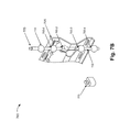
- FIGS. 1A and 1B are diagrams illustrating isometric views of an exemplary embodiment of a mounting assembly
- FIG. 2A is a diagram illustrating a flattened view of an exemplary embodiment of a strut
- FIG. 2B is a diagram illustrating an end view of the strut
- FIG. 2C is a diagram illustrating a top view of the strut
- FIG. 3A is a diagram illustrating a side view of the mounting assembly
- FIGS. 3B and 3C are diagrams illustrating isometric views of the strut
- FIG. 3D is a diagram illustrating a beaded-rod hole
- FIG. 3E is a diagram illustrating a use case of the mounting assembly
- FIG. 4A is a diagram illustrating a view of the mounting assembly
- FIGS. 4B-4F are diagrams illustrating views of an exemplary embodiment of a locking tab
- FIGS. 5A-5D are diagrams illustrating views of another exemplary embodiment of a locking tab
- FIG. 5E is a diagram illustrating an isometric view of another exemplary embodiment a mounting assembly
- FIG. 5F-5I are diagrams illustrating views of yet another exemplary embodiment of a locking tab
- FIGS. 5J and 5K are diagrams illustrating side views of the mounting assembly depicted in FIG. 5E ;
- FIGS. 6A-6C are diagrams illustrating views of a use case of the strut
- FIGS. 7A-7D are diagrams illustrating views of another exemplary embodiment of a mounting assembly.
- FIGS. 8A-8C are diagrams illustrating views of yet another exemplary embodiment of a mounting assembly.
- FIG. 1A is a diagram illustrating an isometric view of an exemplary embodiment of an assembly 100 .
- assembly 100 includes beaded rods 105 - 1 and 105 - 2 (also referred to collectively as beaded rods 105 and individually as beaded rod 105 ), a strut 120 , and locking tabs 140 - 1 and 140 - 2 (also referred to collectively as locking tabs 140 and individually as locking tab 140 ).
- each of beaded rods 105 includes beads 110 - 1 through 110 -X, in which X>1 (also referred to collectively as beads 110 or individually as bead 110 ) and a rod 112 .
- Beaded rod 105 - 1 includes a threaded portion 115 - 1
- beaded rod 105 - 2 includes a threaded portion 115 - 2 (also referred to as threaded portions 115 and threaded portion 115 ).
- bead 110 -X includes threading to allow the assembly of a series of beaded-rods 105 .
- threaded portion 115 - 2 may be threaded into a threading of bead 110 -X.
- Beaded-rod 105 may be made from various materials, such as, for example, metal (e.g., stainless steel, aluminum, etc.) or a non-metallic material (e.g., plastic, a composite, etc.), depending on the load and/or application (e.g., food-grade, pharmaceutical, etc.) of assembly 100 .
- metal e.g., stainless steel, aluminum, etc.
- non-metallic material e.g., plastic, a composite, etc.
- Strut 120 includes holes to receive beaded-rods 105 and holes to allow strut 120 to be secured to a surface (e.g., a wall, etc.), as described further below. Additionally, strut 120 includes holes to receive an attachment (e.g., a U-bolt, a bracket, a clamp, etc.) to secure a fixture (e.g., a pipe, a tube, a conduit, a channel, etc.) to strut 120 .
- an attachment e.g., a U-bolt, a bracket, a clamp, etc.
- strut 120 includes mounting holes 160 - 1 through 160 -Y, in which Y>1 (also referred to collectively as mounting holes 160 and individually as mounting hole 160 ), and mounting holes 170 - 1 through 170 -Z, in which Z>1 (also referred to collectively as mounting holes 170 and individually as mounting hole 170 ).
- Strut 120 also includes mounting holes 150 - 1 through 150 -X, in which X>1 (also referred to collectively as mounting holes 150 and individually as mounting hole 150 ).
- Strut 120 may be made from a material similar to a material of beaded-rod 105 .
- Locking tab 140 includes a flexible member to assist in securing beaded rods 105 with strut 120 .
- FIG. 1B is a diagram illustrating another isometric view showing a reverse side of assembly 100 .
- Assembly 100 is a trapeze-type assembly in which beaded rods 105 suspend strut 120 .
- a wall-mount type assembly is also disclosed in this description. The elements of assembly 100 are described further below.
- FIG. 2A is a flattened view of strut 120 .
- strut 120 includes mounting holes 160 and mounting holes 170 .
- Strut 120 also includes holes 205 - 1 and 205 - 2 (also referred to collectively as holes 205 and individually as hole 205 ).
- Mounting hole 160 and mounting hole 170 each includes a hole to receive an attachment or a portion of an attachment to secure a fixture to strut 120 .
- mounting hole 160 and mounting hole 170 each has an elongated shape. Mounting holes 160 and mounting holes 170 may be equally spaced. Additionally, according to an exemplary embodiment, as illustrated in reference to imaginary line 210 , mounting holes 160 are offset from mounting holes 170 . In this way, mounting holes 160 and mounting holes 170 provide a continuous mounting hole access along the length of strut 120 .
- the continuous mounting hole access may permit a user to mount attachments (e.g., U-bolts, brackets, clamps, etc.) and fixtures (e.g., pipes, tubes, conduits, etc.) with greater flexibility (e.g., closer together, etc.).
- mount attachments e.g., U-bolts, brackets, clamps, etc.
- fixtures e.g., pipes, tubes, conduits, etc.
- Hole 205 includes a hole to receive a fastener (e.g., a bolt, a screw, a nail, etc.). As described further below, according to a wall-mount embodiment, strut 120 may be secured using fasteners and holes 205 .
- a fastener e.g., a bolt, a screw, a nail, etc.
- FIG. 2B is a diagram illustrating an end view of strut 120 .
- strut 120 includes a top wall 270 , back walls 275 - 1 and 275 - 2 (also referred to collectively as back walls 275 and individually as back wall 275 ), sloped walls 280 - 1 and 280 - 2 (also referred to collectively as sloped walls 280 and individually as sloped wall 280 ), an intermediate wall 285 , and a bottom wall 290 .
- back walls 275 - 1 and 275 - 2 extend substantially perpendicular to top wall 270 .
- intermediate wall 285 extends substantially perpendicular to top wall 270 and parallel to back walls 275 .
- Sloped wall 280 - 1 extends between back wall 275 - 1 and intermediate wall 285
- sloped wall 280 - 2 extends between intermediate wall 285 and back wall 275 - 2 .
- sloped walls 280 are sloped approximately thirty-degrees relative to back walls 275 .
- the slopes of sloped walls 280 may be different (e.g., less than or greater than thirty degrees). For example, the slopes may be between twenty degrees and sixty degrees.
- bottom wall 290 is sloped approximately thirty-degrees relative to back walls 275 .
- the slope of bottom wall 290 may be different (e.g., less than or greater than thirty degrees).
- the slopes may be between twenty degrees and sixty degrees.
- bottom wall 290 does not include a lip portion. In this way, the shape of strut 120 facilitates the run-off of water, etc, during cleaning and minimizes the collection of contaminants.
- FIG. 2C is a diagram illustrating a top view of strut 120 .
- top wall 270 includes mounting holes 150 .
- mounting hole 150 has a shape substantially similar to mounting hole 160 and mounting hole 170 .
- FIG. 3A is a diagram illustrating a side view of strut 120 and beaded-rod 105 .
- Beaded-rod 105 suspends strut 120 based on areas of contact 305 - 1 through 305 - 4 (also referred to collectively as area of contacts 305 and individually as area of contact 305 ). As illustrated, each area of contact 305 includes portions of strut 120 in contact with bead 110 of beaded-rod 105 .
- the weight of strut 120 assists in stabilizing strut 120 on beaded rod 105 .
- the coupling of beaded rod 105 with strut 120 is accomplished without a threaded connection.
- FIGS. 3B and 3C are diagrams illustrating isometric view of strut 120 .
- strut 120 includes beaded-rod holes 320 - 1 and 320 - 2 (also referred to collectively as beaded-rod holes 320 and individually as beaded-rod hole 320 ) and beaded-rod holes 322 - 1 and 322 - 2 (also referred to collectively as beaded-rod holes 322 and individually as beaded-rod hole 322 ).
- Beaded-rod hole 320 and beaded-rod hole 322 each includes a hole that is shaped to receive beaded-rod 105 and couple beaded-rod 105 with strut 120 .
- 3D is a diagram illustrating a flattened view of beaded-rod hole 320 / 322 .
- beaded-rod hole 320 / 322 includes a bead hole portion 324 that is shaped to receive bead 110 of beaded-rod 105 and rod hole portions 326 - 1 and 326 - 2 that are shaped to receive rod 112 of beaded-rod 105 .
- beaded-rod hole 320 extends from top wall 270 to back wall 275 - 1 to sloped wall 280 - 1
- beaded-rod hole 322 extends from sloped wall 280 - 2 to back wall 275 - 2 to bottom wall 290 .
- FIG. 3E is a diagram illustrating strut 340 and beaded-rods 105 .
- an attachment 330 e.g., a U-bolt
- strut 120 is attached to strut 120 using mounting holes 150 to secure a fixture 335 (e.g., a pipe).
- Strut 340 is similar to strut 705 , as described further below, in terms of, for example, including rod recesses and the walls defining a beaded-rod hole.
- FIG. 4A is a diagram illustrating a planar view of strut 120 and locking tabs 140 .
- locking tabs 140 assist in securing beaded rods 105 with strut 120 .
- FIG. 4B is a diagram illustrating an end view of locking tab 140 .
- locking tab 140 includes a lip portion 405 , a portion 410 , portions 415 - 1 and 415 - 2 (also referred to collectively as portions 415 and individually as portion 415 ), portions 420 - 1 and 420 - 2 (also referred to collectively as portions 420 and individually as portion 420 ), an intermediate portion 425 , and an end portion 430 .
- portion 410 extends substantially perpendicular from lip portion 405 .
- portion 415 - 1 and portion 420 - 1 extend from intermediate portion 425 and portion 415 - 2 and portion 420 - 2 extend from intermediate portion 425 in a symmetric manner.
- portion 410 and end portion 430 extend within a same, imaginary plane.
- intermediate portion 425 is shaped to receive a portion of rod 112 of beaded-rod 105 .
- intermediate portion 425 may extend in a slightly curved manner.
- FIG. 4C is a diagram illustrating a planar view of locking tab 140 .
- FIGS. 4D through 4F are diagrams illustrating isometric views of locking tab 140 . As illustrated, locking tab 140 extends in an undulating manner from portion 410 to end portion 430 .
- lip portion 405 is placed at an end side of strut 120 and the remaining portions of locking tab 140 extend along another side of strut 120 .
- Locking tab 140 assists in maintaining the position of strut 120 in relation to beaded-rod 105 .
- an edge of locking tab may have contact with an underside of bead 110 and an opposite edge of locking tab 140 may have contact with sloped wall 280 - 2 .
- intermediate portion 425 may have contact with rod portion 112 of beaded-rod 105 .
- Locking tab 140 may provide a spring-like urging based on the material of locking tab 140 and contacts areas of strut 120 and beaded-rod 105 .
- FIGS. 5A-5D are diagrams illustrating another exemplary embodiment of a locking tab.
- a locking tab 505 includes a lip portion 510 a main body portion 515 that includes a rod portion 520 , and an end portion 525 .
- main body portion 515 extends substantially perpendicular from lip portion 510 .
- Rod portion 520 is contoured to receive rod 112 of beaded-rod 105 .
- End portion 525 is wedge-shaped. The shape of end portion 525 may assist a user in inserting locking tab 505 between strut 120 and beaded-rod 105 .
- Locking tab 505 may be used in a manner similar to that illustrated in FIGS. 1A and 1B , in which lip portion 510 is placed at an end side of strut 120 and main body 515 and end portion 525 extend along another side of strut 120 .
- FIG. 5E is a diagram illustrating an isometric view of another exemplary embodiment of a mounting assembly.
- a strut 530 includes a structure similar to strut 120 .
- strut 530 includes tab holes 540 - 1 and 540 - 2 (also referred to collectively as tab holes 540 and individually as tab hole 540 ) that are proximate to holes 205 , which receive a fastener (e.g., for wall-mounting).
- Tab holes 540 are shaped to receive a locking tab 550 .
- FIG. 5F-5I are diagrams illustrating views of yet another exemplary embodiment of a locking tab 550 .
- locking tab 550 includes a head portion 555 , stems 560 - 1 and 560 - 2 (also referred to collectively as stems 560 and individually as stem 560 ), tabs 565 - 1 and 565 - 2 (also referred to collectively as tabs 565 and individually as tab 565 ), a gap 570 , and rod portions 575 - 1 and 575 - 2 (also referred to collectively as rod portions 575 and rod portion 575 ).
- Locking tab 550 may be made from materials similar to those described for strut 120 .
- Head portion 555 includes a dome-shaped portion.
- Stems 560 extend from head portion 555 in a substantially perpendicular manner.
- Stem 560 has a semi-circular column or rod shape.
- Tabs 565 may be flexible and provide a frictional engagement when inserted into tab holes 540 .
- Tabs 565 flare outwardly in relation to stems 560 .
- Gap 570 provides a space between stems 560 .
- Rod portions 575 are curved shaped so as to make contact with rod portion 112 of beaded-rod 105 .
- FIGS. 5J and 5K are diagrams illustrating side views of the mounting assembly depicted in FIG. 5E .
- head portion 555 has a diameter that hides tab hole 540 when head portion 555 rests against an intermediate wall of strut 530 .
- stem 560 may move inward within gap 570 as locking tab 550 is inserted into tab hole 540 , and tabs 565 contact the perimeter wall defining tab hole 540 .
- Stems 560 may move back to their original position once locking tab 550 is completely inserted.
- Tabs 565 may provide a locking effect and rod portions 575 may come in contact with rod portion 112 of beaded-rod 105 or be situated substantially close to rod portion 112 of beaded-rod 105 .
- FIGS. 6A-6B are diagrams illustrating an isometric view of strut 120 .
- FIGS. 6A and 6B illustrate strut 120 according to a wall-mount use case.
- fasteners 605 - 1 and 605 - 2 are inserted in holes 205 .
- stand-offs 610 - 1 and 610 - 2 may be used to provide space between strut 120 and a wall-mountable surface.
- FIG. 6C is a diagram illustrating an end view of a wall-mount use case of strut 120 .
- FIG. 7A is a diagram illustrating an isometric view of another exemplary embodiment of a strut.
- a portion of a strut 705 includes a top wall 710 , back walls 715 - 1 and 715 - 2 (also referred to collectively as back walls 715 and individually as back wall 715 ), sloped walls 720 - 1 and 720 - 2 (also referred to collectively as sloped walls 720 and individually as sloped wall 720 ), an intermediate wall 725 , and a bottom wall 730 .
- Strut 705 may be made from a material previously described for strut 120 .
- back walls 715 extend substantially perpendicular to top wall 710 .
- intermediate wall 725 extends substantially perpendicular to top wall 710 and parallel to back walls 275 .
- sloped walls 720 are sloped approximately thirty-degrees relative to back walls 275 .
- the slopes of sloped walls 720 may be different (e.g., less than or greater than thirty degrees).
- bottom wall 730 is sloped approximately thirty-degrees relative to back walls 275 .
- the slope of bottom wall 730 may different (e.g., (e.g., less than or greater than thirty degrees).
- Strut 705 includes a rod recess 735 situated on top wall 710 and a rod recess 737 situated on bottom wall 730 . As illustrated, rod recess 735 and rod recess 737 is each shaped to receive rod 112 of beaded-rod 105 . Strut 705 includes ribs 740 proximate to mounting holes 745 and ribs 742 proximate to mounting holes 747 . Ribs 740 and ribs 742 provide added support to strut 705 . Similar to mounting holes 160 and 170 , mounting holes 745 and mounting holes 747 include holes to receive an attachment or a portion of an attachment that may be used to secure a fixture. Additionally, similar to mounting holes 160 and 170 , mounting holes 745 are offset from mounting holes 747 .
- Strut 705 also includes a beaded-rod hole 750 . Since FIG. 7A illustrates a portion of strut 705 , strut 705 includes two beaded-rod holes 750 , each proximate to an end of strut 705 . In contrast to strut 120 , strut 705 includes a single beaded-rod hole 750 proximate to the end of strut 705 . Additionally, as illustrated in FIG. 7A , beaded-rod hole 750 is formed by sloped walls 720 and intermediate wall 725 .
- FIG. 7B is a diagram illustrating an isometric view of an exemplary embodiment of an assembly 760 .
- Beaded-rod 105 couples to strut 705 when beaded-rod 105 is inserted into beaded-rod hole 750 .
- beaded-rod 105 suspends strut 705 based on area of contacts 765 - 1 through 765 - 4 (also referred to collectively as area of contacts 765 and individually as area of contact 765 ).
- Each area of contact 765 includes a portion of strut 705 in contact with bead 110 .
- Assembly 760 also includes a locking tab 775 .
- Locking tab 775 is shaped to receive rod 112 of beaded-rod 105 .
- Locking tab 775 assists in securing beaded-rod 105 with strut 705 .
- locking tab 775 may prevent strut 705 from moving (e.g., upwards).
- Locking tab 775 may snap around rod 112 located between area of contacts 765 - 3 and 765 - 4 .
- FIG. 7C is a diagram illustrating a flattened view of strut 705 and beaded-rod 105 .
- strut 705 includes a hole 780 similar to hole 205 of strut 120 .
- Hole 780 may be used to receive a fastener (e.g., a bolt, a screw, a nail, etc.) to secure strut 705 to a surface.
- FIG. 7D is a diagram illustrating a perspective view of strut 705 according to a wall-mount case.
- An attachment 785 e.g., a U-bolt
- secures a fixture 790 e.g., a pipe
- FIG. 8A is a diagram illustrating an isometric view of a portion of an exemplary embodiment of an assembly 800 .
- assembly 800 includes a flattened beaded-rod 805 and a strut 820 .
- Flattened beaded-rod 805 includes a rod 810 , a flattened bead 812 , and a threaded portion 815 .
- flattened beaded-rod 805 may have threading at the other end of flattened beaded-rod 805 to allow a series of flattened beaded-rods 805 to be connected.
- Flattened beaded-rod 805 may be made from a material previously described for beaded-rod 105 .
- Strut 820 includes a top wall 825 , back walls 830 - 1 and 830 - 2 (also referred to collectively as back walls 830 and individually as back wall 830 ), sloped walls 835 - 1 and 835 - 2 (also referred to collectively as sloped walls 835 and individually as sloped wall 835 ), an intermediate wall 840 , and a bottom wall 850 .
- Strut 820 may be made from a material previously described for strut 120 .
- the walls of strut 820 are also similar to strut 120 , such as back walls 830 are substantially perpendicular to top wall 825 , etc.
- top wall 825 of strut 820 extends in a somewhat opposite direction than bottom wall 850 .
- strut 820 includes embossments 860 - 1 and 860 - 2 (also referred to collectively as embossments 860 and individually as embossment 860 ).
- embossments are similarly situated on an opposite side of sloped wall 835 - 2 .
- strut 820 includes embossments 860 on sloped wall 835 - 1 and embossments 862 on an opposite side of sloped wall 835 - 2 .
- strut 820 includes an array of mounting holes 854 along sloped wall 830 - 2 , an array of mounting holes 856 along back wall 830 - 1 , and an array of mounting holes 858 along top wall 825 .
- Strut 820 includes ribs 870 and ribs 872 , a hole 875 for attaching strut 820 to a surface, a rod recess 880 , and a flattened beaded-rod hole 890 .
- a flattened view of strut 820 includes flattened beaded-rod hole 890 and embossments 860 and 862 .
- flattened beaded-rod hole 890 has a uniform shape based on the shape of flattened beads 812 and the method of inserting flattened beaded-rod 805 is inserted in flattened beaded-rod hole 890 .
- flattened beaded-rod 805 is twisted so flattened bead 812 fits into the elongated shape of flattened beaded-rod hole 890 . Thereafter, flattened beaded-rod 805 is twisted again (e.g., to a position illustrated in FIG. 8A ) so portions of flattened bead 812 rest proximate to embossments 860 and 862 .
- an assembly includes a strut that is shaped or contoured to minimize or prevent the collection of contaminants.
- a bottom wall of the strut does not include a lip.
- the strut includes mounting holes that are offset, as described herein.
- the assembly includes beaded rods.
- the beaded rods are configured to suspend a strut without the use of threaded connections to couple the beaded rods to the strut.
- the strut may be coupled to the beaded rods without nuts, washers, bolts, fasteners, and the like.
- beads of the beaded rod are equally spaced.
- the beads are shaped in an oval, an elliptical, or a spherical manner.
- the beads are shaped in an oval-flattened, an elliptical-flattened, or a spherical-flattened manner.
- the beaded rod includes a threaded portion.
- the threaded portion may be used to suspend the beaded rod from a surface (a ceiling, etc.) or other system for hanging objects.
- a strut may be modified to include fewer walls.
- a strut may include a top wall, a back wall, a sloped wall, another back wall, and another sloped wall.
- the strut may include a pair of beaded-rod holes.
- a strut may not include holes 205 within intermediate wall 285 . Rather, the strut may include holes 205 within both back walls 275 . According to yet another example, referring to FIGS. 6A-6C , a strut may be mounted in which the strut is reversed (e.g., horizontally flipped) and attachments and fixtures may be mounted to, for example, the intermediate wall of the strut.
Landscapes
- Engineering & Computer Science (AREA)
- General Engineering & Computer Science (AREA)
- Mechanical Engineering (AREA)
- Connection Of Plates (AREA)
- Mutual Connection Of Rods And Tubes (AREA)
- Body Structure For Vehicles (AREA)
- Tents Or Canopies (AREA)
- Catching Or Destruction (AREA)
Abstract
Description
Claims (18)
Priority Applications (3)
| Application Number | Priority Date | Filing Date | Title |
|---|---|---|---|
| US13/765,847 US9080695B2 (en) | 2012-03-26 | 2013-02-13 | Strut and trapeze system |
| CA2810260A CA2810260C (en) | 2012-03-26 | 2013-03-25 | Strut and trapeze system |
| MX2013003418A MX2013003418A (en) | 2012-03-26 | 2013-03-25 | Strut and trapeze system. |
Applications Claiming Priority (2)
| Application Number | Priority Date | Filing Date | Title |
|---|---|---|---|
| US201261615407P | 2012-03-26 | 2012-03-26 | |
| US13/765,847 US9080695B2 (en) | 2012-03-26 | 2013-02-13 | Strut and trapeze system |
Publications (2)
| Publication Number | Publication Date |
|---|---|
| US20130248660A1 US20130248660A1 (en) | 2013-09-26 |
| US9080695B2 true US9080695B2 (en) | 2015-07-14 |
Family
ID=49210862
Family Applications (1)
| Application Number | Title | Priority Date | Filing Date |
|---|---|---|---|
| US13/765,847 Active US9080695B2 (en) | 2012-03-26 | 2013-02-13 | Strut and trapeze system |
Country Status (3)
| Country | Link |
|---|---|
| US (1) | US9080695B2 (en) |
| CA (1) | CA2810260C (en) |
| MX (1) | MX2013003418A (en) |
Cited By (3)
| Publication number | Priority date | Publication date | Assignee | Title |
|---|---|---|---|---|
| US9907397B2 (en) * | 2015-08-11 | 2018-03-06 | Sung Mook Choi | Clip for fixing pipe |
| USD892599S1 (en) | 2018-11-14 | 2020-08-11 | Eaton Intelligent Power Limited | Support bracket |
| US11274441B2 (en) * | 2017-09-21 | 2022-03-15 | Awi Licensing Llc | Ceiling system |
Families Citing this family (5)
| Publication number | Priority date | Publication date | Assignee | Title |
|---|---|---|---|---|
| US9322169B2 (en) * | 2014-07-18 | 2016-04-26 | Facebook, Inc. | Strut hanger |
| CN108591787B (en) * | 2018-07-04 | 2020-07-03 | 福建工程学院 | Assembled anti-shaking hanging bracket |
| USD884460S1 (en) * | 2018-07-13 | 2020-05-19 | Daniel Bryce Culp | Conduit bracket |
| GB2607250B (en) * | 2019-09-09 | 2024-04-17 | Gripple Ltd | Suspension assembly |
| CN112576817B (en) * | 2020-12-26 | 2022-05-06 | 深圳瑞奇德科技开发有限公司 | Anti-seismic support and hanger and assembling method thereof |
Citations (23)
| Publication number | Priority date | Publication date | Assignee | Title |
|---|---|---|---|---|
| US618603A (en) | 1899-01-31 | Johk henneman | ||
| US1606289A (en) * | 1925-11-11 | 1926-11-09 | Claude E Bowers | Ceiling suspension device |
| US2735157A (en) * | 1956-02-21 | Adjustable casket bed | ||
| US2936988A (en) * | 1957-06-17 | 1960-05-17 | Sunbeam Lighting Company | Adjustable fixture hanger |
| US3226076A (en) * | 1963-04-19 | 1965-12-28 | Heer & Co | Suspension device for cable troughing of perforated sheet metal |
| US3233297A (en) | 1962-02-26 | 1966-02-08 | Erico Prod Inc | Channel clip |
| US3752902A (en) | 1972-10-30 | 1973-08-14 | Dare Prod Inc | Clip-type electrical fence insulator |
| US3854684A (en) | 1973-01-04 | 1974-12-17 | A Moore | Support bracket |
| US3918234A (en) * | 1974-08-12 | 1975-11-11 | Sydney Joseph Weissman | Clip primarily for T-bar ceilings |
| US3938767A (en) | 1974-10-30 | 1976-02-17 | Crouse-Hinds Company | Cable tray |
| US4232847A (en) | 1977-07-11 | 1980-11-11 | Cooper Carl W | Concrete screed or form support |
| US4426822A (en) * | 1982-11-01 | 1984-01-24 | Alcan Aluminum Corporation | Vertical ceiling assembly and stringer therefor |
| US4742979A (en) | 1987-02-19 | 1988-05-10 | Syversten William O | Cable hanger |
| US5102074A (en) | 1989-11-17 | 1992-04-07 | Kyokuto Kogyo Kabushiki Kaisha | Supporting apparatus for piping, supporting instrument for piping and retaining body |
| CA2121373A1 (en) | 1991-10-16 | 1993-04-29 | John Edwin Pink | Support device for services |
| CA2182172A1 (en) | 1994-01-27 | 1995-08-03 | John Edwin Pink | Apparatus for the passive support of overhead solids and support of services |
| US6012691A (en) | 1996-04-09 | 2000-01-11 | Erico International Corporation | Universal beam hanger |
| CA2385956A1 (en) | 1999-10-01 | 2001-04-19 | Hilary Z. Ilijas | Support stand |
| US6748705B2 (en) * | 2002-08-21 | 2004-06-15 | Leszek Orszulak | Slotted M-track support |
| US6807791B2 (en) * | 2001-05-17 | 2004-10-26 | Hilti Aktiengesellschaft | Double-rail profile |
| US20090090820A1 (en) | 2005-02-08 | 2009-04-09 | Potential Design, Inc., Dba Food Grade Strut | Support assemblies for pipes, conduits and tubes |
| US7661915B2 (en) | 2006-10-02 | 2010-02-16 | Whipple Charles E | Trapeze hanger |
| US7946540B2 (en) | 2008-04-25 | 2011-05-24 | Thomas & Betts International, Inc. | Coupling/splice/end bracket for channel |
-
2013
- 2013-02-13 US US13/765,847 patent/US9080695B2/en active Active
- 2013-03-25 MX MX2013003418A patent/MX2013003418A/en active IP Right Grant
- 2013-03-25 CA CA2810260A patent/CA2810260C/en active Active
Patent Citations (28)
| Publication number | Priority date | Publication date | Assignee | Title |
|---|---|---|---|---|
| US618603A (en) | 1899-01-31 | Johk henneman | ||
| US2735157A (en) * | 1956-02-21 | Adjustable casket bed | ||
| US1606289A (en) * | 1925-11-11 | 1926-11-09 | Claude E Bowers | Ceiling suspension device |
| US2936988A (en) * | 1957-06-17 | 1960-05-17 | Sunbeam Lighting Company | Adjustable fixture hanger |
| US3233297A (en) | 1962-02-26 | 1966-02-08 | Erico Prod Inc | Channel clip |
| US3226076A (en) * | 1963-04-19 | 1965-12-28 | Heer & Co | Suspension device for cable troughing of perforated sheet metal |
| US3752902A (en) | 1972-10-30 | 1973-08-14 | Dare Prod Inc | Clip-type electrical fence insulator |
| US3854684A (en) | 1973-01-04 | 1974-12-17 | A Moore | Support bracket |
| US3918234A (en) * | 1974-08-12 | 1975-11-11 | Sydney Joseph Weissman | Clip primarily for T-bar ceilings |
| US3938767A (en) | 1974-10-30 | 1976-02-17 | Crouse-Hinds Company | Cable tray |
| US4232847A (en) | 1977-07-11 | 1980-11-11 | Cooper Carl W | Concrete screed or form support |
| US4426822A (en) * | 1982-11-01 | 1984-01-24 | Alcan Aluminum Corporation | Vertical ceiling assembly and stringer therefor |
| US4742979A (en) | 1987-02-19 | 1988-05-10 | Syversten William O | Cable hanger |
| US5102074A (en) | 1989-11-17 | 1992-04-07 | Kyokuto Kogyo Kabushiki Kaisha | Supporting apparatus for piping, supporting instrument for piping and retaining body |
| CA2121373A1 (en) | 1991-10-16 | 1993-04-29 | John Edwin Pink | Support device for services |
| CA2182172A1 (en) | 1994-01-27 | 1995-08-03 | John Edwin Pink | Apparatus for the passive support of overhead solids and support of services |
| US6012691A (en) | 1996-04-09 | 2000-01-11 | Erico International Corporation | Universal beam hanger |
| CA2385956A1 (en) | 1999-10-01 | 2001-04-19 | Hilary Z. Ilijas | Support stand |
| US6807791B2 (en) * | 2001-05-17 | 2004-10-26 | Hilti Aktiengesellschaft | Double-rail profile |
| US6748705B2 (en) * | 2002-08-21 | 2004-06-15 | Leszek Orszulak | Slotted M-track support |
| US7651056B2 (en) | 2005-02-08 | 2010-01-26 | Potential Design, Inc. | Method of mounting support assemblies for pipes, conduits and tubes |
| US20090090820A1 (en) | 2005-02-08 | 2009-04-09 | Potential Design, Inc., Dba Food Grade Strut | Support assemblies for pipes, conduits and tubes |
| US20100084519A1 (en) | 2005-02-08 | 2010-04-08 | Potential Design, Inc., Dba Food Grade Strut | Support Assemblies for Pipes, Conduits and Tubes |
| US7926766B2 (en) | 2005-02-08 | 2011-04-19 | Potential Design, Inc. | Support assemblies for pipes, conduits and tubes |
| US7931242B2 (en) | 2005-02-08 | 2011-04-26 | Potential Design, Inc. | Support assemblies for pipes, conduits and tubes |
| US20110163208A1 (en) | 2005-02-08 | 2011-07-07 | Potential Design, Inc., Dba Food Grade Strut | Support Assemblies for Pipes, Conduits and Tubes |
| US7661915B2 (en) | 2006-10-02 | 2010-02-16 | Whipple Charles E | Trapeze hanger |
| US7946540B2 (en) | 2008-04-25 | 2011-05-24 | Thomas & Betts International, Inc. | Coupling/splice/end bracket for channel |
Cited By (4)
| Publication number | Priority date | Publication date | Assignee | Title |
|---|---|---|---|---|
| US9907397B2 (en) * | 2015-08-11 | 2018-03-06 | Sung Mook Choi | Clip for fixing pipe |
| US11274441B2 (en) * | 2017-09-21 | 2022-03-15 | Awi Licensing Llc | Ceiling system |
| US12006684B2 (en) | 2017-09-21 | 2024-06-11 | Awi Licensing Llc | Ceiling grid hanger assembly with indexing tabs |
| USD892599S1 (en) | 2018-11-14 | 2020-08-11 | Eaton Intelligent Power Limited | Support bracket |
Also Published As
| Publication number | Publication date |
|---|---|
| CA2810260C (en) | 2019-05-14 |
| US20130248660A1 (en) | 2013-09-26 |
| MX2013003418A (en) | 2014-01-09 |
| CA2810260A1 (en) | 2013-09-26 |
Similar Documents
| Publication | Publication Date | Title |
|---|---|---|
| US9080695B2 (en) | Strut and trapeze system | |
| US7367363B2 (en) | Sanitary conduit support systems | |
| US7931242B2 (en) | Support assemblies for pipes, conduits and tubes | |
| US6474917B2 (en) | Clip nuts | |
| US8840071B2 (en) | Cable support and method | |
| US5848770A (en) | Clevis hanger | |
| EP2589416B1 (en) | Fire protection sprinkler support system | |
| US9683590B2 (en) | Strut system and strut fitting therefor | |
| KR20170084123A (en) | Fitting for channel framing | |
| US20070241238A1 (en) | Hanger | |
| US9976728B2 (en) | Connector assembly for mounting lighting fixture | |
| US20100102175A1 (en) | Cable support | |
| US10443644B2 (en) | Anchor sealing hygienic bracket | |
| US5845882A (en) | Staple hook pipe hanger | |
| US11378113B2 (en) | Fastening unit | |
| CA3064208A1 (en) | Clip hanger and ceiling suspension system incorporating same | |
| JP6450984B1 (en) | Fixture | |
| US9133609B2 (en) | Mounting driver for undermounted sinks |
Legal Events
| Date | Code | Title | Description |
|---|---|---|---|
| FEPP | Fee payment procedure |
Free format text: PAYOR NUMBER ASSIGNED (ORIGINAL EVENT CODE: ASPN); ENTITY STATUS OF PATENT OWNER: LARGE ENTITY |
|
| AS | Assignment |
Owner name: THOMAS & BETTS INTERNATIONAL, INC., DELAWARE Free format text: ASSIGNMENT OF ASSIGNORS INTEREST;ASSIGNOR:MAGNO, JOEY D.;REEL/FRAME:035800/0725 Effective date: 20130208 |
|
| STCF | Information on status: patent grant |
Free format text: PATENTED CASE |
|
| AS | Assignment |
Owner name: THOMAS & BETTS INTERNATIONAL LLC, DELAWARE Free format text: CHANGE OF NAME;ASSIGNOR:THOMAS & BETTS INTERNATIONAL, INC.;REEL/FRAME:040229/0179 Effective date: 20130820 |
|
| FEPP | Fee payment procedure |
Free format text: MAINTENANCE FEE REMINDER MAILED (ORIGINAL EVENT CODE: REM.); ENTITY STATUS OF PATENT OWNER: LARGE ENTITY |
|
| FEPP | Fee payment procedure |
Free format text: SURCHARGE FOR LATE PAYMENT, LARGE ENTITY (ORIGINAL EVENT CODE: M1554); ENTITY STATUS OF PATENT OWNER: LARGE ENTITY |
|
| MAFP | Maintenance fee payment |
Free format text: PAYMENT OF MAINTENANCE FEE, 4TH YEAR, LARGE ENTITY (ORIGINAL EVENT CODE: M1551); ENTITY STATUS OF PATENT OWNER: LARGE ENTITY Year of fee payment: 4 |
|
| MAFP | Maintenance fee payment |
Free format text: PAYMENT OF MAINTENANCE FEE, 8TH YEAR, LARGE ENTITY (ORIGINAL EVENT CODE: M1552); ENTITY STATUS OF PATENT OWNER: LARGE ENTITY Year of fee payment: 8 |