US9077650B2 - Multi-homing in an extended bridge - Google Patents
Multi-homing in an extended bridge Download PDFInfo
- Publication number
- US9077650B2 US9077650B2 US13/839,185 US201313839185A US9077650B2 US 9077650 B2 US9077650 B2 US 9077650B2 US 201313839185 A US201313839185 A US 201313839185A US 9077650 B2 US9077650 B2 US 9077650B2
- Authority
- US
- United States
- Prior art keywords
- port
- packet
- destination
- extender
- link aggregation
- Prior art date
- Legal status (The legal status is an assumption and is not a legal conclusion. Google has not performed a legal analysis and makes no representation as to the accuracy of the status listed.)
- Active, expires
Links
Images


Classifications
-
- H—ELECTRICITY
- H04—ELECTRIC COMMUNICATION TECHNIQUE
- H04L—TRANSMISSION OF DIGITAL INFORMATION, e.g. TELEGRAPHIC COMMUNICATION
- H04L49/00—Packet switching elements
- H04L49/25—Routing or path finding in a switch fabric
- H04L49/253—Routing or path finding in a switch fabric using establishment or release of connections between ports
-
- H—ELECTRICITY
- H04—ELECTRIC COMMUNICATION TECHNIQUE
- H04L—TRANSMISSION OF DIGITAL INFORMATION, e.g. TELEGRAPHIC COMMUNICATION
- H04L12/00—Data switching networks
- H04L12/28—Data switching networks characterised by path configuration, e.g. LAN [Local Area Networks] or WAN [Wide Area Networks]
-
- H—ELECTRICITY
- H04—ELECTRIC COMMUNICATION TECHNIQUE
- H04L—TRANSMISSION OF DIGITAL INFORMATION, e.g. TELEGRAPHIC COMMUNICATION
- H04L12/00—Data switching networks
- H04L12/28—Data switching networks characterised by path configuration, e.g. LAN [Local Area Networks] or WAN [Wide Area Networks]
- H04L12/46—Interconnection of networks
- H04L12/4604—LAN interconnection over a backbone network, e.g. Internet, Frame Relay
- H04L12/462—LAN interconnection over a bridge based backbone
- H04L12/4625—Single bridge functionality, e.g. connection of two networks over a single bridge
-
- H—ELECTRICITY
- H04—ELECTRIC COMMUNICATION TECHNIQUE
- H04L—TRANSMISSION OF DIGITAL INFORMATION, e.g. TELEGRAPHIC COMMUNICATION
- H04L45/00—Routing or path finding of packets in data switching networks
- H04L45/24—Multipath
-
- H—ELECTRICITY
- H04—ELECTRIC COMMUNICATION TECHNIQUE
- H04L—TRANSMISSION OF DIGITAL INFORMATION, e.g. TELEGRAPHIC COMMUNICATION
- H04L45/00—Routing or path finding of packets in data switching networks
- H04L45/24—Multipath
- H04L45/245—Link aggregation, e.g. trunking
-
- H—ELECTRICITY
- H04—ELECTRIC COMMUNICATION TECHNIQUE
- H04L—TRANSMISSION OF DIGITAL INFORMATION, e.g. TELEGRAPHIC COMMUNICATION
- H04L45/00—Routing or path finding of packets in data switching networks
- H04L45/58—Association of routers
- H04L45/586—Association of routers of virtual routers
-
- H—ELECTRICITY
- H04—ELECTRIC COMMUNICATION TECHNIQUE
- H04L—TRANSMISSION OF DIGITAL INFORMATION, e.g. TELEGRAPHIC COMMUNICATION
- H04L45/00—Routing or path finding of packets in data switching networks
- H04L45/66—Layer 2 routing, e.g. in Ethernet based MAN's
-
- H—ELECTRICITY
- H04—ELECTRIC COMMUNICATION TECHNIQUE
- H04L—TRANSMISSION OF DIGITAL INFORMATION, e.g. TELEGRAPHIC COMMUNICATION
- H04L45/00—Routing or path finding of packets in data switching networks
- H04L45/74—Address processing for routing
-
- H—ELECTRICITY
- H04—ELECTRIC COMMUNICATION TECHNIQUE
- H04L—TRANSMISSION OF DIGITAL INFORMATION, e.g. TELEGRAPHIC COMMUNICATION
- H04L65/00—Network arrangements, protocols or services for supporting real-time applications in data packet communication
- H04L65/60—Network streaming of media packets
- H04L65/61—Network streaming of media packets for supporting one-way streaming services, e.g. Internet radio
- H04L65/611—Network streaming of media packets for supporting one-way streaming services, e.g. Internet radio for multicast or broadcast
-
- H—ELECTRICITY
- H04—ELECTRIC COMMUNICATION TECHNIQUE
- H04L—TRANSMISSION OF DIGITAL INFORMATION, e.g. TELEGRAPHIC COMMUNICATION
- H04L12/00—Data switching networks
- H04L12/54—Store-and-forward switching systems
- H04L12/56—Packet switching systems
- H04L12/5601—Transfer mode dependent, e.g. ATM
- H04L2012/5603—Access techniques
-
- Y02B60/33—
-
- Y—GENERAL TAGGING OF NEW TECHNOLOGICAL DEVELOPMENTS; GENERAL TAGGING OF CROSS-SECTIONAL TECHNOLOGIES SPANNING OVER SEVERAL SECTIONS OF THE IPC; TECHNICAL SUBJECTS COVERED BY FORMER USPC CROSS-REFERENCE ART COLLECTIONS [XRACs] AND DIGESTS
- Y02—TECHNOLOGIES OR APPLICATIONS FOR MITIGATION OR ADAPTATION AGAINST CLIMATE CHANGE
- Y02D—CLIMATE CHANGE MITIGATION TECHNOLOGIES IN INFORMATION AND COMMUNICATION TECHNOLOGIES [ICT], I.E. INFORMATION AND COMMUNICATION TECHNOLOGIES AIMING AT THE REDUCTION OF THEIR OWN ENERGY USE
- Y02D30/00—Reducing energy consumption in communication networks
- Y02D30/50—Reducing energy consumption in communication networks in wire-line communication networks, e.g. low power modes or reduced link rate
Definitions
- a network bridge is a Layer 2 device that connects two or more network segments together, thereby creating an aggregate network. It may be desirable to link network segments to the aggregated network that cannot be connected together directly.
- a port extender allows a network segment to be added to the aggregate network.
- a port extender attaches to a media access control (MAC) port of a bridge and provides additional MAC ports that are logically ports of the bridge to which it is attached, which may be referred to as a controlling bridge.
- MAC media access control
- FIG. 1 shows an exemplary extended bridge according to various embodiments of the present disclosure.
- FIG. 2 shows a logical view of the exemplary extended bridge of FIG. 1 according to various embodiments of the present disclosure.
- FIG. 2A is a diagram depicting an exemplary packet flow within the exemplary extended bridge of FIG. 1 according to various embodiments of the present disclosure.
- FIG. 3 shows the exemplary extended bridge of FIG. 1 with multi-homing of end stations according to various embodiments of the present disclosure.
- FIG. 4 shows a logical view of the exemplary extended bridge of FIG. 1 with multi-homing of end stations according to various embodiments of the present disclosure.
- FIG. 5A is a diagram depicting an exemplary packet flow within the exemplary extended bridge of FIG. 1 according to various embodiments of the present disclosure.
- FIG. 5B is a diagram depicting an exemplary packet flow within the exemplary extended bridge of FIG. 1 according to various embodiments of the present disclosure.
- FIG. 5C is a diagram depicting an exemplary multicast packet flow within the exemplary extended bridge of FIG. 1 according to various embodiments of the present disclosure.
- FIG. 6A is a flowchart that provides one example of the operation of a portion of an exemplary controlling bridge within the exemplary extended bridge of FIG. 1 according to various embodiments of the present disclosure.
- FIG. 6B is a flowchart that provides one example of the operation of a portion of exemplary port extenders within the exemplary extended bridge of FIG. 1 according to various embodiments of the present disclosure.
- FIG. 7 shows an exemplary schematic block diagram of an exemplary controlling bridge employed in the exemplary extended bridge of FIG. 1 according to various embodiments of the present disclosure.
- the present disclosure relates to providing multi-homing support in an extended bridge including a controlling bridge and port extenders.
- This multi-homing support may include multi-homing of port extenders into multiple other port extenders with multiple links active.
- This multi-homing support may also include multi-homing of end stations into multiple port extenders with multiple links active.
- FIG. 1 shows an exemplary extended bridge 100 according to various embodiments of the present disclosure.
- the extended bridge 100 includes a controlling bridge 103 having one or more actual ports 106 and a network of port extenders 109 feeding into actual ports 106 of the controlling bridge (CB) 103 .
- the port extenders 109 encapsulate Layer-2 traffic to and from the controlling bridge 103 so as to provide extended ports 112 for the extended bridge 100 .
- the port extenders 109 may be stacked so that one port extender 109 feeds into another port extender 109 .
- the extended bridge 100 employs a single name space across all of the extended ports 112 .
- Port extenders 109 are shown, which are labeled port extender 1 , port extender 2 , port extender 3 , port extender 10 , and port extender 20 .
- Port extenders 1 , 2 , and 3 each feed into respective actual ports 106 (labeled A, B, and C) of the controlling bridge 103 .
- Port extender 10 is multi-homed into port extender 1 and port extender 2
- port extender 20 is multi-homed into port extender 2 and port extender 3 .
- Port extender 10 provides one extended port 112 (labeled extended port M), and port extender 20 provides two extended ports 112 (labeled extended port N and extended port P).
- the extended bridge 100 employs a single extended channel identifier (ECID) namespace across all ports.
- Each extended port 112 of the extended bridge 100 may be assigned an ECID that is unique across the entire extended bridge 100 .
- An extended port 112 may have hierarchically organized ECIDs, and packets may be sent from the same extended port 112 that have different ECIDs.
- Multicast distribution trees that are rooted at the controlling bridge 103 may be constructed across the entire topology of the extended bridge 100 .
- One of more loop-free trees may be constructed and maintained by the controlling bridge 103 .
- FIG. 2 shows a logical view of the exemplary extended bridge 100 ( FIG. 1 ) according to various embodiments of the present disclosure.
- the network of port extenders 109 FIG. 1
- VPLAGs virtual port link aggregation groups
- each extended port 112 may be represented as a virtual port. Due to multi-homing of port extenders 109 ( FIG. 1 ), there may be multiple paths from the controlling bridge 103 to the extended port 112 .
- the multiple paths may be represented in the controlling bridge 103 as a VPLAG 203 .
- Each member of the VPLAG 203 may be an association between a virtual port and a path.
- extended port M As a non-limiting example, there are two paths to extended port M, which corresponds to virtual port (VP) 206 a ; one path is through the actual port A and the other path is through the actual port B of the controlling bridge 103 . Therefore, extended port M is represented in the controlling bridge 103 as a VPLAG 203 a having two members: (VP 206 a , actual port A) and (VP 206 a , actual port B).
- the VP 206 a may be associated with an exemplary ECID attribute of “450.”
- the extended port N corresponding to VP 206 b
- the controlling bridge 103 is represented as a VPLAG 203 b having two members: (VP 206 b , actual port B) and (VP 206 b , actual port C).
- the VP 206 b may be associated with an exemplary ECID attribute of “455.”
- the extended port P, corresponding to VP 206 c is represented in the controlling bridge 103 as a VPLAG 203 c having two members: (VP 206 c , actual port B) and (VP 206 c , actual port C).
- the VP 206 c may be associated with an exemplary ECID attribute of “510.”
- the ECID attributes discussed herein are provided merely as an example to show that ECID attributes may be associated with VPLAGs 203 and unique within the extended bridge 100 .
- FIG. 2A is a diagram depicting an exemplary packet flow 250 within the extended bridge 100 ( FIG. 1 ).
- the diagram depicts a packet flow 250 from extended port M ( FIG. 1 ) to extended port P ( FIG. 1 ) of the extended bridge 100 .
- a unicast flow will first be discussed.
- a packet is received at extended port M having a particular destination address (DA), a particular source address (SA), and a payload.
- the packet is processed by port extender 10 ( FIG. 1 ).
- An extended-tag (ETAG) field is added to the packet by the port extender 10 .
- the ETAG indicates a destination ECID of “450,” corresponding to the ECID of the virtual port 206 a ( FIG. 2 ), and a source ECID of “0.” It is noted that different ECIDs may be employed in the ETAG field for the upstream and downstream directions. Uplinks into port extender 1 ( FIG. 1 ) and port extender 2 ( FIG. 1 ) appear as a VPLAG to the port extender 10 .
- the port extender 10 selects one of the links (either to port extender 1 or port extender 2 ) according to LAG resolution. In this example, the packet is sent to port extender 1 . Port extender 2 may be selected in other examples.
- the port extender 1 sends the packet out on the single uplink port to the actual port A ( FIG. 1 ) of the controlling bridge 103 ( FIG. 1 ). No forwarding lookups or learning is performed at this point in this example.
- the controlling bridge 103 processes the packet.
- the combination of the ingress port A with the destination ECID of “450” is mapped into a source VPLAG of VPLAG 203 a ( FIG. 2 ).
- Forwarding lookups are performed for the packet.
- the destination will be VPLAG 203 c ( FIG. 2 ).
- Source removal checks are performed next. In this case, the packet is not dropped since the source VPLAG and the destination VPLAG are not equal.
- the association between the source media access control (MAC) address SA and the source VPLAG 203 a is learned.
- VPLAG 203 c is then resolved.
- VP 206 c /actual port C is selected, but VP 206 c /actual port B may be selected in other examples.
- the updated ETAG is shown as “ETAG′.” Since this is a unicast packet, the downstream ETAG has a source ECID attribute of “0” and a destination ECID attribute of “510.” “510” is the ECID attribute corresponding to the virtual port 206 c .
- the packet is then sent out of the controlling bridge 103 via the actual port C ( FIG. 1 ).
- the port extender 3 receives the packet.
- the port extender 3 performs a forwarding lookup on the ETAG destination ECID attribute of “510” and sends out the packet to the port extender 20 ( FIG. 1 ).
- the port extender 20 performs a forwarding lookup on the ETAG destination ECID attribute of “510” and forwards the packet out of the extended port P.
- the multicast flow has an upstream flow to the controlling bridge 103 that is the same as the unicast flow previously described. If the forwarding lookup result is a multicast group, the packet is sent out the appropriate set of actual ports 106 ( FIG. 1 ) of the controlling bridge 103 . Since the namespace of the incoming and outgoing ports is the same, the incoming ETAG destination ECID is retained as the ETAG source ECID in the downstream direction. With the situation of FIG. 2A , the ETAG source ECID would be set to “450” in the downstream direction instead of 0 for a multicast flow.
- source removal is performed by comparing the ECID value of the extended port 112 ( FIG. 1 ) with the ETAG source ECID. Since loop-free trees are constructed across the entire extended bridge 100 , only one copy of the packet may be forwarded out of each extended port 112 .
- FIG. 3 shows an exemplary extended bridge 100 ( FIG. 1 ) with multi-homing of end stations 303 according to various embodiments of the present disclosure.
- Two end stations 303 are connected to the extended bridge 100 in this example: end station A and end station B.
- End station A is multi-homed into the extended bridge 100 via extended port M of port extender 10 and extended port N of port extender 20 .
- This multi-homing is represented as a LAG of extended ports 112 .
- This LAG may be assigned a unique ECID.
- End station B is connected to the extended bridge 100 via extended port P of port extender 20 .
- FIG. 4 shows a logical view of the exemplary extended bridge 100 ( FIG. 1 ) with multi-homing of end stations 303 ( FIG. 3 ) according to various embodiments of the present disclosure.
- the LAG of extended ports is represented as a new VPLAG 203 d that includes all members of the individual VPLAGs for each of the extended ports 112 , namely VPLAGs 203 a and 203 b ( FIG. 2 ).
- the VPLAG 203 d includes the associations (VP 206 a , actual port A), (VP 206 a actual port B), (VP 206 b , actual port B), and (VP 206 b , actual port C).
- port extender 20 is configured so that extended port N has an ECID of “1100” for the LAG in this non-limiting example.
- the port extender 20 sends unicast packets with destination ECID of “455” out of extended port N.
- FIG. 5A is a diagram depicting an exemplary packet flow 500 within the extended bridge 100 ( FIG. 1 ).
- the diagram depicts a packet flow 500 from end station A ( FIG. 3 ) to end station B ( FIG. 3 ) of the extended bridge 100 by way of the controlling bridge 103 .
- the end station A At stage 503 , the end station A generates a packet having a source address, a destination address, and a payload.
- the end station A in this example chooses to forward the packet through port extender 10 ( FIG. 3 ), but port extender 20 ( FIG. 3 ) may be chosen as end station A is connected to both port extenders 10 and 20 .
- the port extender 10 receives the packet from end station A and adds an ETAG ECID of “1100” corresponding to the VPLAG 203 d ( FIG. 4 ). Uplinks into port extender 1 ( FIG. 3 ) and port extender 2 ( FIG. 3 ) may appear as a LAG to port extender 10 .
- Port extender 10 selects one of the links via LAG resolution. In this example, the packet is sent to port extender 1 .
- port extender 1 sends the packet out on the uplink port, which is connected to the controlling bridge 103 . No forwarding lookups or learning is performed.
- the destination is VPLAG 203 c ( FIG. 4 ).
- Source removal checks are performed next. In this case, the packet is not dropped since the source VPLAG and destination VPLAG are not the same. The association between the source MAC address and the source VPLAG 203 d is learned. VPLAG 203 c is then resolved. In this example flow, the association (VP 206 c ( FIG. 4 ), actual port C) is selected, and the packet is sent via actual port C ( FIG. 3 ).
- the port extender 3 receives the packet.
- the port extender 3 forwards the packet to port extender 20 .
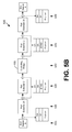
- FIG. 5B is a diagram depicting an exemplary packet flow 530 within the extended bridge 100 ( FIG. 1 ).
- the diagram depicts a packet flow 530 from end station B ( FIG. 3 ) to end station A ( FIG. 3 ) of the extended bridge 100 by way of the controlling bridge 103 .
- the end station B At stage 533 , the end station B generates a packet having a source address, a destination address, and a payload. The end station B forwards the packet via port extender 20 .
- the port extender 20 receives the packet from end station B and adds an ETAG ECID of “510” corresponding to the VP 206 c ( FIG. 4 ). Uplinks into port extender 2 ( FIG. 3 ) and port extender 3 ( FIG. 3 ) may appear as a LAG to port extender 20 .
- Port extender 20 selects one of the links via LAG resolution. In this example, the packet is sent to port extender 2 .
- port extender 2 sends the packet out on the uplink port, which is connected to the controlling bridge 103 .
- the destination is VPLAG 203 d ( FIG. 4 ).
- Source removal checks are performed next. In this case, the packet is not dropped since the source VPLAG and destination VPLAG are not the same. The association between the source MAC address and the source VPLAG 203 c is learned. VPLAG 203 d is then resolved.
- the association (VP 203 b , actual port B) is selected, and the packet is sent via actual port B ( FIG. 3 ).
- the port extender 2 receives the packet.
- the port extender 2 forwards the packet to port extender 20 .
- traffic up to the controlling bridge 103 from end station A uses a source ECID of 1100.
- traffic to end station A uses a destination ECID of 455.
- the traffic to end station A may use a destination ECID of 450.
- the source ECID differs from the destination ECID.
- FIG. 5C is a diagram depicting an exemplary multicast packet flow 560 within the extended bridge 100 ( FIG. 1 ).
- the diagram depicts a multicast packet flow 560 from end station A ( FIG. 3 ) to end station B ( FIG. 3 ) and another end station C of the extended bridge 100 by way of the controlling bridge 103 .
- the end station C is coupled to port extender 10 ( FIG. 3 ).
- the end station A At stage 563 , the end station A generates a packet having a source address, a multicast destination address, and a payload.
- the end station A in this example chooses to forward the packet through port extender 10 , but port extender 20 ( FIG. 3 ) may be chosen as end station A is connected to both port extenders 10 and 20 .
- the port extender 10 receives the packet from end station A and adds an exemplary ETAG ECID of “1100” corresponding to the VPLAG 203 d ( FIG. 4 ). Uplinks into port extender 1 ( FIG. 3 ) and port extender 2 ( FIG. 3 ) may appear as a LAG to port extender 10 .
- Port extender 10 selects one of the links via LAG resolution. In this example, the packet is sent to port extender 1 .
- port extender 1 sends the packet out on the uplink port, which is connected to the controlling bridge 103 . No forwarding lookups or learning is performed.
- the destination is a multicast group, with copies being forwarded out of actual port B ( FIG. 3 ) and actual port C ( FIG.
- ETAG destination ECID for both ETAG′ and ETAG′′ being set to an exemplary multicast ECID of “treeVID1.” Since this is a multicast packet going out on ports with the same namespace as the incoming port, the incoming ETAG ECID value of “1100” is retained as the outgoing ETAG source ECID for both ETAG′ and ETAG′′ as shown.
- the port extender 2 forwards the packet to port extender 10
- the port extender 3 forwards the packet to port extender 20 .
- the incoming ETAG source ECID of “1100” will match the configured ECID (“1100”) for the extended ports M and N. Therefore, no copies will go back to end station A.
- the port extender 10 forwards the packet to end station C
- the port extender 20 forwards the packet to end station B.
- FIG. 6A is a flowchart that provides one example of the operation of a portion of the controlling bridge 103 in an extended bridge 100 ( FIG. 1 ) according to various embodiments. It is understood that the flowchart of FIG. 6A provides merely an example of the many different types of functional arrangements that may be employed to implement the operation of the portion of the controlling bridge 103 as described herein. As an alternative, the flowchart of FIG. 6A may be viewed as depicting an example of steps of a method implemented in the controlling bridge 103 according to one or more embodiments.
- the controlling bridge 103 receives a packet via an ingress port.
- the received packet may include an identifier of a source VPLAG 203 ( FIG. 2 ).
- the received packet may include an identifier of a source virtual port 206 ( FIG. 2 ) of a source port extender 109 ( FIG. 1 ).
- the packet may be received from an intermediate port extender 109 , and the controlling bridge 103 may receive other packets from that intermediate port extender 109 that have an identifier of a different source virtual port 206 of a different source port extender 109 .
- the controlling bridge 103 records an association of the source MAC address and the source VPLAG 203 associated with the packet.
- the controlling bridge 103 determines a destination VPLAG 203 .
- the destination VPLAG 203 may be determined based at least in part on a destination MAC address of an end station 303 ( FIG. 3 ) in the packet.
- the controlling bridge 103 performs a source removal check. For example, the controlling bridge 103 may drop the packet when the source VPLAG 203 is the destination VPLAG 203 .
- the controlling bridge 103 selects one of multiple egress ports of the destination VPLAG 203 determined for the packet.
- the end station 303 may be reachable through any of the egress ports of the destination VPLAG 203 . Thus, for other packets, a different egress port of the destination VPLAG 203 may be selected.
- the controlling bridge 103 embeds the identifier of the source VPLAG 203 in the packet when the destination MAC address corresponds to a multicast group.
- the controlling bridge 103 forwards the packet through the selected egress port.
- the forwarded packet may include an identifier of a destination virtual port 206 to which the end station 303 is connected.
- the packet may be forwarded to a destination port extender 109 that has the destination virtual port 206 .
- the end station 303 may be connected to the destination port extender 109 and to other port extenders 109 of the extended bridge 100 .
- the packet may be forwarded to an intermediate port extender 109 that is configured to forward the packet to the destination port extender 109 based at least in part on the identifier of the destination virtual port 206 . Thereafter, the portion of the controlling bridge 103 ends.
- FIG. 6B is a flowchart that provides one example of the operation of a portion of various port extenders 109 ( FIG. 1 ) in an extended bridge 100 according to various embodiments. It is understood that the flowchart of FIG. 6B provides merely an example of the many different types of functional arrangements that may be employed to implement the operation of the portion of the extended bridge 100 as described herein. As an alternative, the flowchart of FIG. 6B may be viewed as depicting an example of steps of a method implemented in the extended bridge 100 according to one or more embodiments.
- a first port extender 109 receives a packet from an end station 303 ( FIG. 3 ).
- the first port extender 109 determines a destination VPLAG 203 ( FIG. 2 ) based at least in part on a destination MAC address in the packet.
- the first port extender 109 selects one of multiple second port extenders 109 according to the destination VPLAG 203 .
- the first port extender 109 forwards the packet to the selected second port extender 109 .
- the forwarded packet includes an identifier of a destination virtual port 206 ( FIG. 2 ).
- the selected second port extender 109 receives the forwarded packet from the first port extender 109 .
- the selected second port extender 109 forwards the packet to a controlling bridge 103 ( FIG. 1 ) of the extended bridge 100 .
- a third port extender 109 receives another packet from the end station 303 .
- the selected second port extender 109 receives the other packet from the third port extender 109 .
- the selected second port extender 109 forwards the other packet to the controlling bridge 103 . Thereafter, the portion of the extended bridge 100 ends.
- FIG. 7 shows an exemplary schematic block diagram of the controlling bridge 103 employed in the exemplary extended bridge 100 ( FIGS. 1 & 3 ) according to various embodiments of the present disclosure.
- the controlling bridge 103 includes at least one processor circuit, for example, having a processor 703 and a memory 706 , both of which are coupled to a local interface 709 .
- the controlling bridge 103 may comprise, for example, a network gateway device, a server device, a router, and/or other types of computing devices.
- the local interface 709 may comprise, for example, a data bus with an accompanying address/control bus or other bus structure as can be appreciated.
- One or more network interfaces 712 may be coupled to the local interface 709 .
- Stored in the memory 706 are both data and several components that are executable by the processor 703 .
- stored in the memory 706 and executable by the processor 703 is forwarding logic 715 and potentially other logic.
- Also stored in the memory 706 may be forwarding data 718 and other data.
- the forwarding data 718 may comprise VPLAG data 721 , loop-free tree data 724 , and other data.
- an operating system may be stored in the memory 706 and executable by the processor 703 .
- One or more software components may be stored in the memory 706 and may be executable by the processor 703 .
- the term “executable” means a program file that is in a form that can ultimately be run by the processor 703 .
- Examples of executable programs may be, for example, a compiled program that can be translated into machine code in a format that can be loaded into a random access portion of the memory 706 and run by the processor 703 , source code that may be expressed in proper format such as object code that is capable of being loaded into a random access portion of the memory 706 and executed by the processor 703 , or source code that may be interpreted by another executable program to generate instructions in a random access portion of the memory 706 to be executed by the processor 703 , etc.
- An executable program may be stored in any portion or component of the memory 706 including, for example, random access memory (RAM), read-only memory (ROM), hard drive, solid-state drive, USB flash drive, memory card, optical disc such as compact disc (CD) or digital versatile disc (DVD), floppy disk, magnetic tape, or other memory components.
- RAM random access memory
- ROM read-only memory
- hard drive solid-state drive
- USB flash drive USB flash drive
- memory card such as compact disc (CD) or digital versatile disc (DVD), floppy disk, magnetic tape, or other memory components.
- CD compact disc
- DVD digital versatile disc
- the memory 706 is defined herein as including both volatile and nonvolatile memory and data storage components. Volatile components are those that do not retain data values upon loss of power. Nonvolatile components are those that retain data upon a loss of power.
- the memory 706 may comprise, for example, random access memory (RAM), read-only memory (ROM), hard disk drives, solid-state drives, USB flash drives, memory cards accessed via a memory card reader, floppy disks accessed via an associated floppy disk drive, optical discs accessed via an optical disc drive, magnetic tapes accessed via an appropriate tape drive, and/or other memory components, or a combination of any two or more of these memory components.
- the RAM may comprise, for example, static random access memory (SRAM), dynamic random access memory (DRAM), or magnetic random access memory (MRAM) and other such devices.
- the ROM may comprise, for example, a programmable read-only memory (PROM), an erasable programmable read-only memory (EPROM), an electrically erasable programmable read-only memory (EEPROM), or other like memory device.
- the processor 703 may represent multiple processors 703 and the memory 706 may represent multiple memories 706 that operate in parallel processing circuits, respectively.
- the local interface 709 may be an appropriate network that facilitates communication between any two of the multiple processors 703 , between any processor 703 and any of the memories 706 , or between any two of the memories 706 , etc.
- the local interface 709 may comprise additional systems designed to coordinate this communication, including, for example, performing load balancing.
- the processor 703 may be of electrical or of some other available construction.
- each block may represent a module, segment, or portion of code that comprises program instructions to implement the specified logical function(s).
- the program instructions may be embodied in the form of source code that comprises human-readable statements written in a programming language or machine code that comprises numerical instructions recognizable by a suitable execution system such as a processor 703 in a computer system or other system.
- the machine code may be converted from the source code, etc.
- each block may represent a circuit or a number of interconnected circuits to implement the specified logical function(s).
- FIGS. 6A and 6B show a specific order of execution, it is understood that the order of execution may differ from that which is depicted. For example, the order of execution of two or more blocks may be scrambled relative to the order shown. Also, two or more blocks shown in succession in FIGS. 6A and 6B may be executed concurrently or with partial concurrence. Further, in some embodiments, one or more of the blocks shown in FIGS. 6A and 6B may be skipped or omitted. In addition, any number of counters, state variables, warning semaphores, or messages might be added to the logical flow described herein, for purposes of enhanced utility, accounting, performance measurement, or providing troubleshooting aids, etc. It is understood that all such variations are within the scope of the present disclosure.
- any logic or application described herein that comprises software or code can be embodied in any computer-readable medium for use by or in connection with an instruction execution system such as, for example, a processor 703 in a computer system or other system.
- the logic may comprise, for example, statements including instructions and declarations that can be fetched from the computer-readable medium and executed by the instruction execution system.
- a “computer-readable medium” can be any medium that can contain, store, or maintain the logic or application described herein for use by or in connection with the instruction execution system.
- the computer-readable medium can comprise any one of many physical media such as, for example, magnetic, optical, or semiconductor media.
- the computer-readable medium may comprise transitory propagation media. More specific examples of a suitable computer-readable medium would include, but are not limited to, magnetic tapes, magnetic floppy diskettes, magnetic hard drives, memory cards, solid-state drives, USB flash drives, or optical discs.
- the computer-readable medium may be a random access memory (RAM) including, for example, static random access memory (SRAM) and dynamic random access memory (DRAM), or magnetic random access memory (MRAM).
- RAM random access memory
- SRAM static random access memory
- DRAM dynamic random access memory
- MRAM magnetic random access memory
- the computer-readable medium may be a read-only memory (ROM), a programmable read-only memory (PROM), an erasable programmable read-only memory (EPROM), an electrically erasable programmable read-only memory (EEPROM), or other type of memory device.
- ROM read-only memory
- PROM programmable read-only memory
- EPROM erasable programmable read-only memory
- EEPROM electrically erasable programmable read-only memory
Landscapes
- Engineering & Computer Science (AREA)
- Computer Networks & Wireless Communication (AREA)
- Signal Processing (AREA)
- Multimedia (AREA)
- Data Exchanges In Wide-Area Networks (AREA)
Priority Applications (6)
| Application Number | Priority Date | Filing Date | Title |
|---|---|---|---|
| US13/839,185 US9077650B2 (en) | 2012-05-31 | 2013-03-15 | Multi-homing in an extended bridge |
| TW102115602A TWI521922B (zh) | 2012-05-31 | 2013-05-01 | 擴展網橋之系統及其方法 |
| EP13002542.2A EP2670090B1 (en) | 2012-05-31 | 2013-05-15 | Multi-homing in an extended bridge |
| CN201310215584.XA CN103457818B (zh) | 2012-05-31 | 2013-05-31 | 扩展网桥中的多宿主 |
| KR1020130062444A KR101460054B1 (ko) | 2012-05-31 | 2013-05-31 | 확장형 브리지 내의 멀티-호밍 |
| US14/731,827 US9819612B2 (en) | 2012-05-31 | 2015-06-05 | Multi-homing in an extended bridge |
Applications Claiming Priority (2)
| Application Number | Priority Date | Filing Date | Title |
|---|---|---|---|
| US201261653858P | 2012-05-31 | 2012-05-31 | |
| US13/839,185 US9077650B2 (en) | 2012-05-31 | 2013-03-15 | Multi-homing in an extended bridge |
Related Child Applications (1)
| Application Number | Title | Priority Date | Filing Date |
|---|---|---|---|
| US14/731,827 Continuation US9819612B2 (en) | 2012-05-31 | 2015-06-05 | Multi-homing in an extended bridge |
Publications (2)
| Publication Number | Publication Date |
|---|---|
| US20130322457A1 US20130322457A1 (en) | 2013-12-05 |
| US9077650B2 true US9077650B2 (en) | 2015-07-07 |
Family
ID=48576170
Family Applications (2)
| Application Number | Title | Priority Date | Filing Date |
|---|---|---|---|
| US13/839,185 Active 2033-08-06 US9077650B2 (en) | 2012-05-31 | 2013-03-15 | Multi-homing in an extended bridge |
| US14/731,827 Active 2033-09-06 US9819612B2 (en) | 2012-05-31 | 2015-06-05 | Multi-homing in an extended bridge |
Family Applications After (1)
| Application Number | Title | Priority Date | Filing Date |
|---|---|---|---|
| US14/731,827 Active 2033-09-06 US9819612B2 (en) | 2012-05-31 | 2015-06-05 | Multi-homing in an extended bridge |
Country Status (5)
| Country | Link |
|---|---|
| US (2) | US9077650B2 (zh) |
| EP (1) | EP2670090B1 (zh) |
| KR (1) | KR101460054B1 (zh) |
| CN (1) | CN103457818B (zh) |
| TW (1) | TWI521922B (zh) |
Cited By (4)
| Publication number | Priority date | Publication date | Assignee | Title |
|---|---|---|---|---|
| US20150271105A1 (en) * | 2012-05-31 | 2015-09-24 | Broadcom Corporation | Multi-homing in an extended bridge |
| US20160162429A1 (en) * | 2014-12-09 | 2016-06-09 | Dell Products L.P. | System and method for non-unicast/desintation lookup fail (dlf) load balancing |
| US20170063668A1 (en) * | 2015-08-27 | 2017-03-02 | Dell Products L.P. | Layer 3 routing loop prevention system |
| EP3439248A4 (en) * | 2016-03-31 | 2019-02-27 | New H3C Technologies Co., Ltd. | CONFIGURATION OF A CONNECTION GATE GROUP |
Families Citing this family (39)
| Publication number | Priority date | Publication date | Assignee | Title |
|---|---|---|---|---|
| US20140044129A1 (en) * | 2012-08-10 | 2014-02-13 | Duane Edward MENTZE | Multicast packet forwarding in a network |
| US9294396B2 (en) * | 2013-03-12 | 2016-03-22 | Dell Products L.P. | Port extender |
| US9176767B2 (en) * | 2013-04-11 | 2015-11-03 | Cisco Technology, Inc. | Network interface card device pass-through with multiple nested hypervisors |
| CN104348735B (zh) * | 2013-07-23 | 2017-09-15 | 新华三技术有限公司 | 堆叠系统中的报文转发方法及装置 |
| US20150163072A1 (en) * | 2013-12-05 | 2015-06-11 | Broadcom Corporation | Virtual Port Extender |
| US9473425B2 (en) * | 2013-12-06 | 2016-10-18 | Dell Products L.P. | Systems and methods for integrating wireless local area networks on extended bridges |
| US20150312151A1 (en) * | 2014-04-29 | 2015-10-29 | Dell Products L.P. | Enhanced load distribution of non-unicast traffic to multi-homed nodes in a port extender environment |
| US9984028B2 (en) * | 2014-10-31 | 2018-05-29 | Arris Enterprises Llc | Redundancy for port extender chains |
| WO2016072972A1 (en) * | 2014-11-04 | 2016-05-12 | Hewlett Packard Enterprise Development Lp | Bridge port extender |
| US10348519B2 (en) * | 2014-11-20 | 2019-07-09 | Hewlett Packard Enterprise Development Lp | Virtual target port aggregation |
| CN104539532B (zh) * | 2015-01-09 | 2018-03-20 | 烽火通信科技股份有限公司 | 基于lte基站回传业务的nni保护uni的系统及方法 |
| US10050906B2 (en) * | 2015-04-21 | 2018-08-14 | Verizon Patent And Licensing Inc. | Virtual node having separate control and data planes |
| CN106169982B (zh) * | 2015-05-27 | 2020-09-08 | 中兴通讯股份有限公司 | 扩展端口的处理方法、装置及系统 |
| US10148595B2 (en) * | 2015-10-16 | 2018-12-04 | Arris Enterprises Llc | Handling dynamic port/LAG changes without breaking communication in an extended bridge |
| US10719341B2 (en) | 2015-12-02 | 2020-07-21 | Nicira, Inc. | Learning of tunnel endpoint selections |
| US10069646B2 (en) | 2015-12-02 | 2018-09-04 | Nicira, Inc. | Distribution of tunnel endpoint mapping information |
| CN108432189B (zh) * | 2015-12-02 | 2021-04-20 | Nicira股份有限公司 | 多个隧道端点上的负载平衡 |
| US10164885B2 (en) | 2015-12-02 | 2018-12-25 | Nicira, Inc. | Load balancing over multiple tunnel endpoints |
| US9912616B2 (en) * | 2015-12-02 | 2018-03-06 | Nicira, Inc. | Grouping tunnel endpoints of a bridge cluster |
| US10313231B1 (en) | 2016-02-08 | 2019-06-04 | Barefoot Networks, Inc. | Resilient hashing for forwarding packets |
| CN105791170A (zh) * | 2016-03-08 | 2016-07-20 | 盛科网络(苏州)有限公司 | 基于逻辑端口实现端口扩展的方法及装置 |
| CN105847107B (zh) * | 2016-03-31 | 2019-07-05 | 新华三技术有限公司 | 一种系统以及设置链路聚合组方法和装置 |
| CN107294846B (zh) * | 2016-03-31 | 2020-12-04 | 新华三技术有限公司 | 报文转发方法和装置 |
| CN105991445B (zh) * | 2016-03-31 | 2020-07-07 | 新华三技术有限公司 | 链路聚合组的设置方法和装置 |
| CN107493181B (zh) * | 2016-06-13 | 2022-01-28 | 深圳市中兴通讯技术服务有限责任公司 | 虚拟扩展端口的指示方法和装置 |
| CN107493185B (zh) * | 2016-06-13 | 2022-03-25 | 中兴通讯股份有限公司 | 一种接口扩展设备的配置信息通告方法及其装置 |
| CN107528784B (zh) * | 2016-06-21 | 2021-02-26 | 新华三技术有限公司 | 报文转发方法和装置 |
| CN107547334B (zh) * | 2016-06-28 | 2021-01-26 | 新华三技术有限公司 | 一种报文转发方法及装置 |
| CN108124285B (zh) * | 2016-11-29 | 2020-11-06 | 新华三技术有限公司 | 一种报文传输方法和装置 |
| CN106789526B (zh) * | 2016-11-29 | 2019-12-13 | 北京元心科技有限公司 | 多系统网络连接的方法及装置 |
| CN108259345B (zh) * | 2016-12-30 | 2021-01-26 | 新华三技术有限公司 | 端口生成方法和装置 |
| CN106533889A (zh) * | 2016-12-30 | 2017-03-22 | 盛科网络(苏州)有限公司 | 芯片中bpe跨端口扩展设备实现链路聚合的方法 |
| US10404619B1 (en) * | 2017-03-05 | 2019-09-03 | Barefoot Networks, Inc. | Link aggregation group failover for multicast |
| US10382332B2 (en) * | 2017-05-12 | 2019-08-13 | Juniper Networks, Inc. | Route signaling and convergence in EVPN of port extenders |
| CN108418752B (zh) * | 2017-07-24 | 2019-11-08 | 新华三技术有限公司 | 一种聚合组的创建方法和装置 |
| CN107769980A (zh) * | 2017-11-01 | 2018-03-06 | 盛科网络(苏州)有限公司 | 一种用于扩展桥的转发多播报文的方法和装置 |
| CN109995647A (zh) * | 2018-01-03 | 2019-07-09 | 中兴通讯股份有限公司 | 一种物理层链路传输设备及装置 |
| GB2583521B (en) * | 2019-05-02 | 2022-01-12 | Samsung Electronics Co Ltd | Relay network routing |
| US11743191B1 (en) | 2022-07-25 | 2023-08-29 | Vmware, Inc. | Load balancing over tunnel endpoint groups |
Citations (6)
| Publication number | Priority date | Publication date | Assignee | Title |
|---|---|---|---|---|
| US20050198371A1 (en) * | 2004-02-19 | 2005-09-08 | Smith Michael R. | Interface bundles in virtual network devices |
| US20080112323A1 (en) | 2006-11-13 | 2008-05-15 | Corrigent Systems Ltd. | Hash-based multi-homing |
| US20080123528A1 (en) | 2002-01-31 | 2008-05-29 | Wyatt Richard M | Trunking in a matrix |
| KR20090101270A (ko) | 2006-12-21 | 2009-09-24 | 코리전트 시스템즈 리미티드 | 링크 애그리게이션 포트를 통한 멀티캐스트 트래픽 포워딩 |
| US20100157844A1 (en) * | 2008-12-19 | 2010-06-24 | Nortel Networks Limited | Resilient attachment to provider link state bridging (plsb) networks |
| US20120307828A1 (en) * | 2011-06-06 | 2012-12-06 | Broadcom Corporation | Method and System of Frame Forwarding with Link Aggregation in Distributed Ethernet Bridges |
Family Cites Families (3)
| Publication number | Priority date | Publication date | Assignee | Title |
|---|---|---|---|---|
| JP4862743B2 (ja) * | 2007-05-17 | 2012-01-25 | 日本電気株式会社 | ノード、通信方法およびノード用プログラム |
| CN101170512B (zh) * | 2007-11-21 | 2010-04-21 | 中兴通讯股份有限公司 | 报文业务处理方法 |
| US9077650B2 (en) * | 2012-05-31 | 2015-07-07 | Broadcom Corporation | Multi-homing in an extended bridge |
-
2013
- 2013-03-15 US US13/839,185 patent/US9077650B2/en active Active
- 2013-05-01 TW TW102115602A patent/TWI521922B/zh not_active IP Right Cessation
- 2013-05-15 EP EP13002542.2A patent/EP2670090B1/en active Active
- 2013-05-31 CN CN201310215584.XA patent/CN103457818B/zh active Active
- 2013-05-31 KR KR1020130062444A patent/KR101460054B1/ko not_active IP Right Cessation
-
2015
- 2015-06-05 US US14/731,827 patent/US9819612B2/en active Active
Patent Citations (8)
| Publication number | Priority date | Publication date | Assignee | Title |
|---|---|---|---|---|
| US20080123528A1 (en) | 2002-01-31 | 2008-05-29 | Wyatt Richard M | Trunking in a matrix |
| US20120243411A1 (en) * | 2002-01-31 | 2012-09-27 | Mosaid Technologies Incorporated | Trunking in a matrix |
| US20050198371A1 (en) * | 2004-02-19 | 2005-09-08 | Smith Michael R. | Interface bundles in virtual network devices |
| US20080112323A1 (en) | 2006-11-13 | 2008-05-15 | Corrigent Systems Ltd. | Hash-based multi-homing |
| KR20090101270A (ko) | 2006-12-21 | 2009-09-24 | 코리전트 시스템즈 리미티드 | 링크 애그리게이션 포트를 통한 멀티캐스트 트래픽 포워딩 |
| US7697525B2 (en) | 2006-12-21 | 2010-04-13 | Corrigent Systems Ltd. | Forwarding multicast traffic over link aggregation ports |
| US20100157844A1 (en) * | 2008-12-19 | 2010-06-24 | Nortel Networks Limited | Resilient attachment to provider link state bridging (plsb) networks |
| US20120307828A1 (en) * | 2011-06-06 | 2012-12-06 | Broadcom Corporation | Method and System of Frame Forwarding with Link Aggregation in Distributed Ethernet Bridges |
Non-Patent Citations (4)
| Title |
|---|
| European Search Report in co-pending, related EP Application No. 13002542.2, mailed Sep. 13, 2013. |
| Raeber, Rene: "Bridge Port Extension" (IEEE 1-15 P802.1Qbh), Sep. 9, 2010, pp. 1-21, XP055078034, URL: http://www.itc22.com/fileadmin/ITC22-files/VBPE-IBM-Version-rraeber-v-00.pdf. |
| Raeber, Rene: "Bridge Port Extension" (IEEE 1-15 P802.1Qbh), Sep. 9, 2010, pp. 1-21, XP055078034. * |
| Virtual Bridge Port Extension (IEEE P802.1Qbh), René Raeber, XP055078034 (Sep. 2010) (21 pages). |
Cited By (9)
| Publication number | Priority date | Publication date | Assignee | Title |
|---|---|---|---|---|
| US20150271105A1 (en) * | 2012-05-31 | 2015-09-24 | Broadcom Corporation | Multi-homing in an extended bridge |
| US9819612B2 (en) * | 2012-05-31 | 2017-11-14 | Avago Technologies General Ip (Singapore) Pte. Ltd. | Multi-homing in an extended bridge |
| US20160162429A1 (en) * | 2014-12-09 | 2016-06-09 | Dell Products L.P. | System and method for non-unicast/desintation lookup fail (dlf) load balancing |
| US9792242B2 (en) * | 2014-12-09 | 2017-10-17 | Dell Products Lp | Systems and methods for non-unicast/destination lookup fail (DLF) load balancing |
| US20170063668A1 (en) * | 2015-08-27 | 2017-03-02 | Dell Products L.P. | Layer 3 routing loop prevention system |
| US9929937B2 (en) * | 2015-08-27 | 2018-03-27 | Dell Products L.P. | Layer 3 routing loop prevention system |
| EP3439248A4 (en) * | 2016-03-31 | 2019-02-27 | New H3C Technologies Co., Ltd. | CONFIGURATION OF A CONNECTION GATE GROUP |
| US20190089625A1 (en) * | 2016-03-31 | 2019-03-21 | New H3C Technologies Co., Ltd. | Setting link aggregation group |
| US10797991B2 (en) * | 2016-03-31 | 2020-10-06 | New H3C Technologies Co., Ltd. | Setting link aggregation group |
Also Published As
| Publication number | Publication date |
|---|---|
| KR20130137538A (ko) | 2013-12-17 |
| TW201349800A (zh) | 2013-12-01 |
| CN103457818A (zh) | 2013-12-18 |
| KR101460054B1 (ko) | 2014-11-11 |
| EP2670090A1 (en) | 2013-12-04 |
| EP2670090B1 (en) | 2017-07-12 |
| US20150271105A1 (en) | 2015-09-24 |
| CN103457818B (zh) | 2018-11-20 |
| TWI521922B (zh) | 2016-02-11 |
| US9819612B2 (en) | 2017-11-14 |
| US20130322457A1 (en) | 2013-12-05 |
Similar Documents
| Publication | Publication Date | Title |
|---|---|---|
| US9819612B2 (en) | Multi-homing in an extended bridge | |
| US11743123B2 (en) | Managed switch architectures: software managed switches, hardware managed switches, and heterogeneous managed switches | |
| US10063470B2 (en) | Data center network system based on software-defined network and packet forwarding method, address resolution method, routing controller thereof | |
| US9007895B2 (en) | Method for routing data packets in a fat tree network | |
| US10122614B2 (en) | Failure protection for traffic-engineered bit indexed explicit replication | |
| CN103200069B (zh) | 一种报文处理的方法和设备 | |
| US10230576B2 (en) | Managing administrative statuses of hardware VTEPs | |
| US10601702B1 (en) | Flexible packet replication and filtering for multicast/broadcast | |
| US10164885B2 (en) | Load balancing over multiple tunnel endpoints | |
| US20170163598A1 (en) | Learning of tunnel endpoint selections | |
| US9112728B2 (en) | Implementing control planes for hybrid networks | |
| CN108322338B (zh) | 一种广播抑制方法和vtep设备 | |
| US20190305985A1 (en) | Packet forwarding | |
| US9497124B1 (en) | Systems and methods for load balancing multicast traffic | |
| CN107659484B (zh) | 从vlan网络接入vxlan网络的方法、装置及系统 | |
| US11784922B2 (en) | Scalable overlay multicast routing in multi-tier edge gateways | |
| US20200044894A1 (en) | Mac address synchronization | |
| US10027589B1 (en) | Apparatus, system, and method for achieving redundancy and load-balancing across communication layers within networks | |
| US20200007617A1 (en) | Technologies for scrambling in load balancers | |
| US20190297016A1 (en) | Transmitting packet | |
| CN108880892B (zh) | 一种报文处理方法和装置 | |
| US10050887B2 (en) | Load balancing method, device and storage medium | |
| US11658897B2 (en) | Loop prevention system | |
| CN106850434B (zh) | 一种vxlan的传输控制方法、系统及处理设备 | |
| JP2015158763A (ja) | データ配信制御システム、データ配信制御方法、及び、データ配信制御プログラム |
Legal Events
| Date | Code | Title | Description |
|---|---|---|---|
| AS | Assignment |
Owner name: BROADCOM CORPORATION, CALIFORNIA Free format text: ASSIGNMENT OF ASSIGNORS INTEREST;ASSIGNORS:BUDHIA, RUPA;BABU, BIJU RAVINDRANATHA;KALKUNTE, MOHAN VENKATACHAR;AND OTHERS;REEL/FRAME:030141/0536 Effective date: 20130315 |
|
| STCF | Information on status: patent grant |
Free format text: PATENTED CASE |
|
| AS | Assignment |
Owner name: BANK OF AMERICA, N.A., AS COLLATERAL AGENT, NORTH CAROLINA Free format text: PATENT SECURITY AGREEMENT;ASSIGNOR:BROADCOM CORPORATION;REEL/FRAME:037806/0001 Effective date: 20160201 Owner name: BANK OF AMERICA, N.A., AS COLLATERAL AGENT, NORTH Free format text: PATENT SECURITY AGREEMENT;ASSIGNOR:BROADCOM CORPORATION;REEL/FRAME:037806/0001 Effective date: 20160201 |
|
| AS | Assignment |
Owner name: AVAGO TECHNOLOGIES GENERAL IP (SINGAPORE) PTE. LTD., SINGAPORE Free format text: ASSIGNMENT OF ASSIGNORS INTEREST;ASSIGNOR:BROADCOM CORPORATION;REEL/FRAME:041706/0001 Effective date: 20170120 Owner name: AVAGO TECHNOLOGIES GENERAL IP (SINGAPORE) PTE. LTD Free format text: ASSIGNMENT OF ASSIGNORS INTEREST;ASSIGNOR:BROADCOM CORPORATION;REEL/FRAME:041706/0001 Effective date: 20170120 |
|
| AS | Assignment |
Owner name: BROADCOM CORPORATION, CALIFORNIA Free format text: TERMINATION AND RELEASE OF SECURITY INTEREST IN PATENTS;ASSIGNOR:BANK OF AMERICA, N.A., AS COLLATERAL AGENT;REEL/FRAME:041712/0001 Effective date: 20170119 |
|
| AS | Assignment |
Owner name: AVAGO TECHNOLOGIES INTERNATIONAL SALES PTE. LIMITE Free format text: MERGER;ASSIGNOR:AVAGO TECHNOLOGIES GENERAL IP (SINGAPORE) PTE. LTD.;REEL/FRAME:047229/0408 Effective date: 20180509 |
|
| AS | Assignment |
Owner name: AVAGO TECHNOLOGIES INTERNATIONAL SALES PTE. LIMITE Free format text: CORRECTIVE ASSIGNMENT TO CORRECT THE EFFECTIVE DATE PREVIOUSLY RECORDED ON REEL 047229 FRAME 0408. ASSIGNOR(S) HEREBY CONFIRMS THE THE EFFECTIVE DATE IS 09/05/2018;ASSIGNOR:AVAGO TECHNOLOGIES GENERAL IP (SINGAPORE) PTE. LTD.;REEL/FRAME:047349/0001 Effective date: 20180905 |
|
| MAFP | Maintenance fee payment |
Free format text: PAYMENT OF MAINTENANCE FEE, 4TH YEAR, LARGE ENTITY (ORIGINAL EVENT CODE: M1551); ENTITY STATUS OF PATENT OWNER: LARGE ENTITY Year of fee payment: 4 |
|
| AS | Assignment |
Owner name: AVAGO TECHNOLOGIES INTERNATIONAL SALES PTE. LIMITE Free format text: CORRECTIVE ASSIGNMENT TO CORRECT THE PATENT NUMBER 9,385,856 TO 9,385,756 PREVIOUSLY RECORDED AT REEL: 47349 FRAME: 001. ASSIGNOR(S) HEREBY CONFIRMS THE MERGER;ASSIGNOR:AVAGO TECHNOLOGIES GENERAL IP (SINGAPORE) PTE. LTD.;REEL/FRAME:051144/0648 Effective date: 20180905 |
|
| MAFP | Maintenance fee payment |
Free format text: PAYMENT OF MAINTENANCE FEE, 8TH YEAR, LARGE ENTITY (ORIGINAL EVENT CODE: M1552); ENTITY STATUS OF PATENT OWNER: LARGE ENTITY Year of fee payment: 8 |