EP2670090A1 - Multi-homing in an extended bridge - Google Patents
Multi-homing in an extended bridge Download PDFInfo
- Publication number
- EP2670090A1 EP2670090A1 EP13002542.2A EP13002542A EP2670090A1 EP 2670090 A1 EP2670090 A1 EP 2670090A1 EP 13002542 A EP13002542 A EP 13002542A EP 2670090 A1 EP2670090 A1 EP 2670090A1
- Authority
- EP
- European Patent Office
- Prior art keywords
- port
- packet
- destination
- extender
- extended
- Prior art date
- Legal status (The legal status is an assumption and is not a legal conclusion. Google has not performed a legal analysis and makes no representation as to the accuracy of the status listed.)
- Granted
Links
Images


Classifications
-
- H—ELECTRICITY
- H04—ELECTRIC COMMUNICATION TECHNIQUE
- H04L—TRANSMISSION OF DIGITAL INFORMATION, e.g. TELEGRAPHIC COMMUNICATION
- H04L49/00—Packet switching elements
- H04L49/25—Routing or path finding in a switch fabric
- H04L49/253—Routing or path finding in a switch fabric using establishment or release of connections between ports
-
- H—ELECTRICITY
- H04—ELECTRIC COMMUNICATION TECHNIQUE
- H04L—TRANSMISSION OF DIGITAL INFORMATION, e.g. TELEGRAPHIC COMMUNICATION
- H04L12/00—Data switching networks
- H04L12/28—Data switching networks characterised by path configuration, e.g. LAN [Local Area Networks] or WAN [Wide Area Networks]
- H04L12/46—Interconnection of networks
- H04L12/4604—LAN interconnection over a backbone network, e.g. Internet, Frame Relay
- H04L12/462—LAN interconnection over a bridge based backbone
- H04L12/4625—Single bridge functionality, e.g. connection of two networks over a single bridge
-
- H—ELECTRICITY
- H04—ELECTRIC COMMUNICATION TECHNIQUE
- H04L—TRANSMISSION OF DIGITAL INFORMATION, e.g. TELEGRAPHIC COMMUNICATION
- H04L12/00—Data switching networks
- H04L12/28—Data switching networks characterised by path configuration, e.g. LAN [Local Area Networks] or WAN [Wide Area Networks]
-
- H—ELECTRICITY
- H04—ELECTRIC COMMUNICATION TECHNIQUE
- H04L—TRANSMISSION OF DIGITAL INFORMATION, e.g. TELEGRAPHIC COMMUNICATION
- H04L12/00—Data switching networks
- H04L12/28—Data switching networks characterised by path configuration, e.g. LAN [Local Area Networks] or WAN [Wide Area Networks]
- H04L12/46—Interconnection of networks
- H04L12/4604—LAN interconnection over a backbone network, e.g. Internet, Frame Relay
- H04L12/462—LAN interconnection over a bridge based backbone
-
- H—ELECTRICITY
- H04—ELECTRIC COMMUNICATION TECHNIQUE
- H04L—TRANSMISSION OF DIGITAL INFORMATION, e.g. TELEGRAPHIC COMMUNICATION
- H04L45/00—Routing or path finding of packets in data switching networks
- H04L45/24—Multipath
-
- H—ELECTRICITY
- H04—ELECTRIC COMMUNICATION TECHNIQUE
- H04L—TRANSMISSION OF DIGITAL INFORMATION, e.g. TELEGRAPHIC COMMUNICATION
- H04L45/00—Routing or path finding of packets in data switching networks
- H04L45/24—Multipath
- H04L45/245—Link aggregation, e.g. trunking
-
- H—ELECTRICITY
- H04—ELECTRIC COMMUNICATION TECHNIQUE
- H04L—TRANSMISSION OF DIGITAL INFORMATION, e.g. TELEGRAPHIC COMMUNICATION
- H04L45/00—Routing or path finding of packets in data switching networks
- H04L45/58—Association of routers
- H04L45/586—Association of routers of virtual routers
-
- H—ELECTRICITY
- H04—ELECTRIC COMMUNICATION TECHNIQUE
- H04L—TRANSMISSION OF DIGITAL INFORMATION, e.g. TELEGRAPHIC COMMUNICATION
- H04L45/00—Routing or path finding of packets in data switching networks
- H04L45/66—Layer 2 routing, e.g. in Ethernet based MAN's
-
- H—ELECTRICITY
- H04—ELECTRIC COMMUNICATION TECHNIQUE
- H04L—TRANSMISSION OF DIGITAL INFORMATION, e.g. TELEGRAPHIC COMMUNICATION
- H04L45/00—Routing or path finding of packets in data switching networks
- H04L45/74—Address processing for routing
-
- H—ELECTRICITY
- H04—ELECTRIC COMMUNICATION TECHNIQUE
- H04L—TRANSMISSION OF DIGITAL INFORMATION, e.g. TELEGRAPHIC COMMUNICATION
- H04L65/00—Network arrangements, protocols or services for supporting real-time applications in data packet communication
- H04L65/60—Network streaming of media packets
- H04L65/61—Network streaming of media packets for supporting one-way streaming services, e.g. Internet radio
- H04L65/611—Network streaming of media packets for supporting one-way streaming services, e.g. Internet radio for multicast or broadcast
-
- H—ELECTRICITY
- H04—ELECTRIC COMMUNICATION TECHNIQUE
- H04L—TRANSMISSION OF DIGITAL INFORMATION, e.g. TELEGRAPHIC COMMUNICATION
- H04L12/00—Data switching networks
- H04L12/54—Store-and-forward switching systems
- H04L12/56—Packet switching systems
- H04L12/5601—Transfer mode dependent, e.g. ATM
- H04L2012/5603—Access techniques
-
- Y—GENERAL TAGGING OF NEW TECHNOLOGICAL DEVELOPMENTS; GENERAL TAGGING OF CROSS-SECTIONAL TECHNOLOGIES SPANNING OVER SEVERAL SECTIONS OF THE IPC; TECHNICAL SUBJECTS COVERED BY FORMER USPC CROSS-REFERENCE ART COLLECTIONS [XRACs] AND DIGESTS
- Y02—TECHNOLOGIES OR APPLICATIONS FOR MITIGATION OR ADAPTATION AGAINST CLIMATE CHANGE
- Y02D—CLIMATE CHANGE MITIGATION TECHNOLOGIES IN INFORMATION AND COMMUNICATION TECHNOLOGIES [ICT], I.E. INFORMATION AND COMMUNICATION TECHNOLOGIES AIMING AT THE REDUCTION OF THEIR OWN ENERGY USE
- Y02D30/00—Reducing energy consumption in communication networks
- Y02D30/50—Reducing energy consumption in communication networks in wire-line communication networks, e.g. low power modes or reduced link rate
Definitions
- a network bridge is a Layer 2 device that connects two or more network segments together, thereby creating an aggregate network. It may be desirable to link network segments to the aggregated network that cannot be connected together directly.
- a port extender allows a network segment to be added to the aggregate network.
- a port extender attaches to a media access control (MAC) port of a bridge and provides additional MAC ports that are logically ports of the bridge to which it is attached, which may be referred to as a controlling bridge.
- MAC media access control
- a system comprises:
- the received packet includes an identifier of a source virtual port link aggregation group of an extended port.
- the identifier of the source virtual port link aggregation group is different from the identifier of the destination virtual port link aggregation group.
- the packet is received from an intermediate port extender via the ingress port, and the controlling bridge device further comprises circuitry configured to:
- the packet is forwarded to an intermediate port extender, the intermediate port extender being configured to forward the packet to a destination port extender based at least in part on the identifier of the destination virtual port.
- the packet is forwarded to a destination port extender having the destination virtual port.
- the end station is connected to the destination port extender and another port extender of the extended bridge.
- controlling bridge device further comprises circuitry configured to:
- a method comprises:
- the forwarding comprises forwarding, in the controlling bridge device, the packet to the destination port extender.
- the forwarding comprises forwarding, in the controlling bridge device, the packet to an intermediate port extender different from the destination port extender.
- the method further comprises:
- the method further comprises embedding, in the controlling bridge device, the identifier of the source virtual port link aggregation group in the forwarded packet when the destination MAC address corresponds to a multicast group.
- the method further comprises maintaining, in the controlling bridge device, a plurality of loop-free multicast distribution trees in the extended bridge.
- a method comprises:
- the method further comprises:
- the method further comprises:
- the method further comprises receiving, in the third port extender, the other packet from the end station.
- the method further comprises:
- the method further comprises:
- FIG. 1 shows an exemplary extended bridge according to various embodiments of the present disclosure.
- FIG. 2 shows a logical view of the exemplary extended bridge of FIG. 1 according to various embodiments of the present disclosure.
- FIG. 2A is a diagram depicting an exemplary packet flow within the exemplary extended bridge of FIG. 1 according to various embodiments of the present disclosure.
- FIG. 3 shows the exemplary extended bridge of FIG. 1 with multi-homing of end stations according to various embodiments of the present disclosure.
- FIG. 4 shows a logical view of the exemplary extended bridge of FIG. 1 with multi-homing of end stations according to various embodiments of the present disclosure.
- FIG. 5A is a diagram depicting an exemplary packet flow within the exemplary extended bridge of FIG. 1 according to various embodiments of the present disclosure.
- FIG. 5B is a diagram depicting an exemplary packet flow within the exemplary extended bridge of FIG. 1 according to various embodiments of the present disclosure.
- FIG. 5C is a diagram depicting an exemplary multicast packet flow within the exemplary extended bridge of FIG. 1 according to various embodiments of the present disclosure.
- FIG. 6A is a flowchart that provides one example of the operation of a portion of an exemplary controlling bridge within the exemplary extended bridge of FIG. 1 according to various embodiments of the present disclosure.
- FIG. 6B is a flowchart that provides one example of the operation of a portion of exemplary port extenders within the exemplary extended bridge of FIG. 1 according to various embodiments of the present disclosure.
- FIG. 7 shows an exemplary schematic block diagram of an exemplary controlling bridge employed in the exemplary extended bridge of FIG. 1 according to various embodiments of the present disclosure.
- the present disclosure relates to providing multi-homing support in an extended bridge including a controlling bridge and port extenders.
- This multi-homing support may include multi-homing of port extenders into multiple other port extenders with multiple links active.
- This multi-homing support may also include multi-homing of end stations into multiple port extenders with multiple links active.
- FIG. 1 shows an exemplary extended bridge 100 according to various embodiments of the present disclosure.
- the extended bridge 100 includes a controlling bridge 103 having one or more actual ports 106 and a network of port extenders 109 feeding into actual ports 106 of the controlling bridge (CB) 103.
- the port extenders 109 encapsulate Layer-2 traffic to and from the controlling bridge 103 so as to provide extended ports 112 for the extended bridge 100.
- the port extenders 109 may be stacked so that one port extender 109 feeds into another port extender 109.
- the extended bridge 100 employs a single name space across all of the extended ports 112.
- port extender 1 five port extenders 109 are shown, which are labeled port extender 1, port extender 2, port extender 3, port extender 10, and port extender 20.
- Port extenders 1, 2, and 3 each feed into respective actual ports 106 (labeled A, B, and C) of the controlling bridge 103.
- Port extender 10 is multi-homed into port extender 1 and port extender 2
- port extender 20 is multi-homed into port extender 2 and port extender 3.
- Port extender 10 provides one extended port 112 (labeled extended port M), and port extender 20 provides two extended ports 112 (labeled extended port N and extended port P).
- the extended bridge 100 employs a single extended channel identifier (ECID) namespace across all ports.
- Each extended port 112 of the extended bridge 100 may be assigned an ECID that is unique across the entire extended bridge 100.
- An extended port 112 may have hierarchically organized ECIDs, and packets may be sent from the same extended port 112 that have different ECIDs.
- Multicast distribution trees that are rooted at the controlling bridge 103 may be constructed across the entire topology of the extended bridge 100. One of more such loop-free trees may be constructed and maintained by the controlling bridge 103.
- FIG. 2 shows a logical view of the exemplary extended bridge 100 ( FIG. 1 ) according to various embodiments of the present disclosure.
- the network of port extenders 109 FIG. 1
- VPLAGs virtual port link aggregation groups
- each extended port 112 may be represented as a virtual port.
- the multiple paths may be represented in the controlling bridge 103 as a VPLAG 203.
- Each member of the VPLAG 203 may be an association between a virtual port and a path.
- extended port M which corresponds to virtual port (VP) 206a; one path is through the actual port A and the other path is through the actual port B of the controlling bridge 103. Therefore, extended port M is represented in the controlling bridge 103 as a VPLAG 203a having two members: (VP 206a, actual port A) and (VP 206a, actual port B). The VP 206a may be associated with an exemplary ECID attribute of "450.”
- the extended port N corresponding to VP 206b, is represented in the controlling bridge 103 as a VPLAG 203b having two members: (VP 206b, actual port B) and (VP 206b, actual port C).
- the VP 206b may be associated with an exemplary ECID attribute of "455.”
- the extended port P corresponding to VP 206c, is represented in the controlling bridge 103 as a VPLAG 203c having two members: (VP 206c, actual port B) and (VP 206c, actual port C).
- the VP 206c may be associated with an exemplary ECID attribute of "510.”
- the ECID attributes discussed herein are provided merely as an example to show that ECID attributes may be associated with VPLAGs 203 and unique within the extended bridge 100.
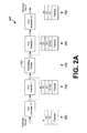
- FIG. 2A is a diagram depicting an exemplary packet flow 250 within the extended bridge 100 ( FIG. 1 ).
- the diagram depicts a packet flow 250 from extended port M ( FIG. 1 ) to extended port P ( FIG. 1 ) of the extended bridge 100.
- a unicast flow will first be discussed.
- a packet is received at extended port M having a particular destination address (DA), a particular source address (SA), and a payload.
- the packet is processed by port extender 10 ( FIG. 1 ).
- An extended-tag (ETAG) field is added to the packet by the port extender 10.
- the ETAG indicates a destination ECID of "450,” corresponding to the ECID of the virtual port 206a ( FIG. 2 ), and a source ECID of "0.” It is noted that different ECIDs may be employed in the ETAG field for the upstream and downstream directions. Uplinks into port extender 1 ( FIG. 1 ) and port extender 2 ( FIG. 1 ) appear as a VPLAG to the port extender 10.
- the port extender 10 selects one of the links (either to port extender 1 or port extender 2) according to LAG resolution. In this example, the packet is sent to port extender 1. Port extender 2 may be selected in other examples.
- the port extender 1 sends the packet out on the single uplink port to the actual port A ( FIG. 1 ) of the controlling bridge 103 ( FIG. 1 ). No forwarding lookups or learning is performed at this point in this example.
- the controlling bridge 103 processes the packet.
- the combination of the ingress port A with the destination ECID of "450" is mapped into a source VPLAG of VPLAG 203a ( FIG. 2 ).
- Forwarding lookups are performed for the packet.
- the destination will be VPLAG 203c ( FIG. 2 ).
- Source removal checks are performed next. In this case, the packet is not dropped since the source VPLAG and the destination VPLAG are not equal.
- the association between the source media access control (MAC) address SA and the source VPLAG 203a is learned.
- VPLAG 203c is then resolved. In this example flow, (VP 206c ( FIG.
- actual port C) is selected, but (VP 206c, actual port B) may be selected in other examples.
- the updated ETAG is shown as "ETAG'.” Since this is a unicast packet, the downstream ETAG has a source ECID attribute of "0" and a destination ECID attribute of "510.” "510" is the ECID attribute corresponding to the virtual port 206c.
- the packet is then sent out of the controlling bridge 103 via the actual port C ( FIG. 1 ).
- the port extender 3 receives the packet.
- the port extender 3 performs a forwarding lookup on the ETAG destination ECID attribute of "510" and sends out the packet to the port extender 20 ( FIG. 1 ).
- the port extender 20 performs a forwarding lookup on the ETAG destination ECID attribute of "510" and forwards the packet out of the extended port P.
- the multicast flow has an upstream flow to the controlling bridge 103 that is the same as the unicast flow previously described. If the forwarding lookup result is a multicast group, the packet is sent out the appropriate set of actual ports 106 ( FIG. 1 ) of the controlling bridge 103. Since the namespace of the incoming and outgoing ports is the same, the incoming ETAG destination ECID is retained as the ETAG source ECID in the downstream direction. With the situation of FIG. 2A , the ETAG source ECID would be set to "450" in the downstream direction instead of 0 for a multicast flow. At the port extenders 109 ( FIG. 1 ), source removal is performed by comparing the ECID value of the extended port 112 ( FIG. 1 ) with the ETAG source ECID. Since loop-free trees are constructed across the entire extended bridge 100, only one copy of the packet may be forwarded out of each extended port 112.
- FIG. 3 shows an exemplary extended bridge 100 ( FIG. 1 ) with multi-homing of end stations 303 according to various embodiments of the present disclosure.
- Two end stations 303 are connected to the extended bridge 100 in this example: end station A and end station B.
- End station A is multi-homed into the extended bridge 100 via extended port M of port extender 10 and extended port N of port extender 20.
- This multi-homing is represented as a LAG of extended ports 112. This LAG may be assigned a unique ECID.
- End station B is connected to the extended bridge 100 via extended port P of port extender 20.
- FIG. 4 shows a logical view of the exemplary extended bridge 100 ( FIG. 1 ) with multi-homing of end stations 303 ( FIG. 3 ) according to various embodiments of the present disclosure.
- the LAG of extended ports is represented as a new VPLAG 203d that includes all members of the individual VPLAGs for each of the extended ports 112, namely VPLAGs 203a and 203b ( FIG. 2 ).
- the VPLAG 203d includes the associations (VP 206a, actual port A), (VP 206a actual port B), (VP 206b, actual port B), and (VP 206b, actual port C).
- port extender 20 is configured so that extended port N has an ECID of "1100" for the LAG in this non-limiting example.
- the port extender 20 sends unicast packets with destination ECID of "455" out of extended port N.
- FIG. 5A is a diagram depicting an exemplary packet flow 500 within the extended bridge 100 ( FIG. 1 ).
- the diagram depicts a packet flow 500 from end station A ( FIG. 3 ) to end station B ( FIG. 3 ) of the extended bridge 100 by way of the controlling bridge 103.
- the end station A At stage 503, the end station A generates a packet having a source address, a destination address, and a payload.
- the end station A in this example chooses to forward the packet through port extender 10 ( FIG. 3 ), but port extender 20 ( FIG. 3 ) may be chosen as end station A is connected to both port extenders 10 and 20.
- the port extender 10 receives the packet from end station A and adds an ETAG ECID of "1100" corresponding to the VPLAG 203d ( FIG. 4 ). Uplinks into port extender 1 ( FIG. 3 ) and port extender 2 ( FIG. 3 ) may appear as a LAG to port extender 10.
- Port extender 10 selects one of the links via LAG resolution. In this example, the packet is sent to port extender 1.
- port extender 1 sends the packet out on the uplink port, which is connected to the controlling bridge 103. No forwarding lookups or learning is performed.
- the destination is VPLAG 203c ( FIG. 4 ).
- Source removal checks are performed next. In this case, the packet is not dropped since the source VPLAG and destination VPLAG are not the same. The association between the source MAC address and the source VPLAG 203d is learned. VPLAG 203c is then resolved. In this example flow, the association (VP 206c ( FIG. 4 ), actual port C) is selected, and the packet is sent via actual port C ( FIG. 3 ).
- the port extender 3 receives the packet.
- the port extender 3 forwards the packet to port extender 20.
- FIG. 5B is a diagram depicting an exemplary packet flow 530 within the extended bridge 100 ( FIG. 1 ).
- the diagram depicts a packet flow 530 from end station B ( FIG. 3 ) to end station A ( FIG. 3 ) of the extended bridge 100 by way of the controlling bridge 103.
- the end station B At stage 533, the end station B generates a packet having a source address, a destination address, and a payload. The end station B forwards the packet via port extender 20.
- the port extender 20 receives the packet from end station B and adds an ETAG ECID of "510" corresponding to the VP 206c ( FIG. 4 ). Uplinks into port extender 2 ( FIG. 3 ) and port extender 3 ( FIG. 3 ) may appear as a LAG to port extender 20.
- Port extender 20 selects one of the links via LAG resolution. In this example, the packet is sent to port extender 2.
- port extender 2 sends the packet out on the uplink port, which is connected to the controlling bridge 103. No forwarding lookups or learning is performed.
- the destination is VPLAG 203d ( FIG. 4 ).
- Source removal checks are performed next. In this case, the packet is not dropped since the source VPLAG and destination VPLAG are not the same. The association between the source MAC address and the source VPLAG 203c is learned. VPLAG 203d is then resolved.
- the association (VP 203b, actual port B) is selected, and the packet is sent via actual port B ( FIG. 3 ).
- ETAG ECID "455" is set in "ETAG',” and this ECID value is also associated with VP 203b.
- the port extender 2 receives the packet.
- the port extender 2 forwards the packet to port extender 20.
- traffic up to the controlling bridge 103 from end station A uses a source ECID of 1100.
- traffic to end station A uses a destination ECID of 455.
- the traffic to end station A may use a destination ECID of 450.
- the source ECID differs from the destination ECID.
- FIG. 5C is a diagram depicting an exemplary multicast packet flow 560 within the extended bridge 100 ( FIG. 1 ).
- the diagram depicts a multicast packet flow 560 from end station A ( FIG. 3 ) to end station B ( FIG. 3 ) and another end station C of the extended bridge 100 by way of the controlling bridge 103.
- the end station C is coupled to port extender 10 ( FIG. 3 ).
- the end station A At stage 563, the end station A generates a packet having a source address, a multicast destination address, and a payload.
- the end station A in this example chooses to forward the packet through port extender 10, but port extender 20 ( FIG. 3 ) may be chosen as end station A is connected to both port extenders 10 and 20.
- the port extender 10 receives the packet from end station A and adds an exemplary ETAG ECID of "1100" corresponding to the VPLAG 203d ( FIG. 4 ). Uplinks into port extender 1 ( FIG. 3 ) and port extender 2 ( FIG. 3 ) may appear as a LAG to port extender 10.
- Port extender 10 selects one of the links via LAG resolution. In this example, the packet is sent to port extender 1.
- port extender 1 sends the packet out on the uplink port, which is connected to the controlling bridge 103. No forwarding lookups or learning is performed.
- the destination is a multicast group, with copies being forwarded out of actual port B ( FIG. 3 ) and actual port C ( FIG.
- ETAG destination ECID for both ETAG' and ETAG being set to an exemplary multicast ECID of "treeVID1.” Since this is a multicast packet going out on ports with the same namespace as the incoming port, the incoming ETAG ECID value of "1100" is retained as the outgoing ETAG source ECID for both ETAG' and ETAG" as shown.
- the port extender 2 forwards the packet to port extender 10, and the port extender 3 forwards the packet to port extender 20.
- the incoming ETAG source ECID of "1100” will match the configured ECID ("1100") for the extended ports M and N. Therefore, no copies will go back to end station A.
- the port extender 10 forwards the packet to end station C, and the port extender 20 forwards the packet to end station B.
- FIG. 6A is a flowchart that provides one example of the operation of a portion of the controlling bridge 103 in an extended bridge 100 ( FIG. 1 ) according to various embodiments. It is understood that the flowchart of FIG. 6A provides merely an example of the many different types of functional arrangements that may be employed to implement the operation of the portion of the controlling bridge 103 as described herein. As an alternative, the flowchart of FIG. 6A may be viewed as depicting an example of steps of a method implemented in the controlling bridge 103 according to one or more embodiments.
- the controlling bridge 103 receives a packet via an ingress port.
- the received packet may include an identifier of a source VPLAG 203 ( FIG. 2 ).
- the received packet may include an identifier of a source virtual port 206 ( FIG. 2 ) of a source port extender 109 ( FIG. 1 ).
- the packet may be received from an intermediate port extender 109, and the controlling bridge 103 may receive other packets from that intermediate port extender 109 that have an identifier of a different source virtual port 206 of a different source port extender 109.
- the controlling bridge 103 records an association of the source MAC address and the source VPLAG 203 associated with the packet.
- the controlling bridge 103 determines a destination VPLAG 203.
- the destination VPLAG 203 may be determined based at least in part on a destination MAC address of an end station 303 ( FIG. 3 ) in the packet.
- the controlling bridge 103 performs a source removal check. For example, the controlling bridge 103 may drop the packet when the source VPLAG 203 is the destination VPLAG 203.
- the controlling bridge 103 selects one of multiple egress ports of the destination VPLAG 203 determined for the packet.
- the end station 303 may be reachable through any of the egress ports of the destination VPLAG 203. Thus, for other packets, a different egress port of the destination VPLAG 203 may be selected.
- the controlling bridge 103 embeds the identifier of the source VPLAG 203 in the packet when the destination MAC address corresponds to a multicast group.
- the controlling bridge 103 forwards the packet through the selected egress port.
- the forwarded packet may include an identifier of a destination virtual port 206 to which the end station 303 is connected.
- the packet may be forwarded to a destination port extender 109 that has the destination virtual port 206.
- the end station 303 may be connected to the destination port extender 109 and to other port extenders 109 of the extended bridge 100.
- the packet may be forwarded to an intermediate port extender 109 that is configured to forward the packet to the destination port extender 109 based at least in part on the identifier of the destination virtual port 206. Thereafter, the portion of the controlling bridge 103 ends.
- FIG. 6B is a flowchart that provides one example of the operation of a portion of various port extenders 109 ( FIG. 1 ) in an extended bridge 100 according to various embodiments. It is understood that the flowchart of FIG. 6B provides merely an example of the many different types of functional arrangements that may be employed to implement the operation of the portion of the extended bridge 100 as described herein. As an alternative, the flowchart of FIG. 6B may be viewed as depicting an example of steps of a method implemented in the extended bridge 100 according to one or more embodiments.
- a first port extender 109 receives a packet from an end station 303 ( FIG. 3 ).
- the first port extender 109 determines a destination VPLAG 203 ( FIG. 2 ) based at least in part on a destination MAC address in the packet.
- the first port extender 109 selects one of multiple second port extenders 109 according to the destination VPLAG 203.
- the first port extender 109 forwards the packet to the selected second port extender 109.
- the forwarded packet includes an identifier of a destination virtual port 206 ( FIG. 2 ).
- the selected second port extender 109 receives the forwarded packet from the first port extender 109.
- the selected second port extender 109 forwards the packet to a controlling bridge 103 ( FIG. 1 ) of the extended bridge 100.
- a third port extender 109 receives another packet from the end station 303.
- the selected second port extender 109 receives the other packet from the third port extender 109.
- the selected second port extender 109 forwards the other packet to the controlling bridge 103. Thereafter, the portion of the extended bridge 100 ends.
- FIG. 7 shows an exemplary schematic block diagram of the controlling bridge 103 employed in the exemplary extended bridge 100 ( FIGS. 1 & 3 ) according to various embodiments of the present disclosure.
- the controlling bridge 103 includes at least one processor circuit, for example, having a processor 703 and a memory 706, both of which are coupled to a local interface 709.
- the controlling bridge 103 may comprise, for example, a network gateway device, a server device, a router, and/or other types of computing devices.
- the local interface 709 may comprise, for example, a data bus with an accompanying address/control bus or other bus structure as can be appreciated.
- One or more network interfaces 712 may be coupled to the local interface 709.
- Stored in the memory 706 are both data and several components that are executable by the processor 703.
- stored in the memory 706 and executable by the processor 703 is forwarding logic 715 and potentially other logic.
- Also stored in the memory 706 may be forwarding data 718 and other data.
- the forwarding data 718 may comprise VPLAG data 721, loop-free tree data 724, and other data.
- an operating system may be stored in the memory 706 and executable by the processor 703.
- One or more software components may be stored in the memory 706 and may be executable by the processor 703.
- the term "executable” means a program file that is in a form that can ultimately be run by the processor 703.
- Examples of executable programs may be, for example, a compiled program that can be translated into machine code in a format that can be loaded into a random access portion of the memory 706 and run by the processor 703, source code that may be expressed in proper format such as object code that is capable of being loaded into a random access portion of the memory 706 and executed by the processor 703, or source code that may be interpreted by another executable program to generate instructions in a random access portion of the memory 706 to be executed by the processor 703, etc.
- An executable program may be stored in any portion or component of the memory 706 including, for example, random access memory (RAM), read-only memory (ROM), hard drive, solid-state drive, USB flash drive, memory card, optical disc such as compact disc (CD) or digital versatile disc (DVD), floppy disk, magnetic tape, or other memory components.
- RAM random access memory
- ROM read-only memory
- hard drive solid-state drive
- USB flash drive USB flash drive
- memory card such as compact disc (CD) or digital versatile disc (DVD), floppy disk, magnetic tape, or other memory components.
- CD compact disc
- DVD digital versatile disc
- the memory 706 is defined herein as including both volatile and nonvolatile memory and data storage components. Volatile components are those that do not retain data values upon loss of power. Nonvolatile components are those that retain data upon a loss of power.
- the memory 706 may comprise, for example, random access memory (RAM), read-only memory (ROM), hard disk drives, solid-state drives, USB flash drives, memory cards accessed via a memory card reader, floppy disks accessed via an associated floppy disk drive, optical discs accessed via an optical disc drive, magnetic tapes accessed via an appropriate tape drive, and/or other memory components, or a combination of any two or more of these memory components.
- the RAM may comprise, for example, static random access memory (SRAM), dynamic random access memory (DRAM), or magnetic random access memory (MRAM) and other such devices.
- the ROM may comprise, for example, a programmable read-only memory (PROM), an erasable programmable read-only memory (EPROM), an electrically erasable programmable read-only memory (EEPROM), or other like memory device.
- the processor 703 may represent multiple processors 703 and the memory 706 may represent multiple memories 706 that operate in parallel processing circuits, respectively.
- the local interface 709 may be an appropriate network that facilitates communication between any two of the multiple processors 703, between any processor 703 and any of the memories 706, or between any two of the memories 706, etc.
- the local interface 709 may comprise additional systems designed to coordinate this communication, including, for example, performing load balancing.
- the processor 703 may be of electrical or of some other available construction.
- each block may represent a module, segment, or portion of code that comprises program instructions to implement the specified logical function(s).
- the program instructions may be embodied in the form of source code that comprises human-readable statements written in a programming language or machine code that comprises numerical instructions recognizable by a suitable execution system such as a processor 703 in a computer system or other system.
- the machine code may be converted from the source code, etc.
- each block may represent a circuit or a number of interconnected circuits to implement the specified logical function(s).
- FIGS. 6A and 6B show a specific order of execution, it is understood that the order of execution may differ from that which is depicted. For example, the order of execution of two or more blocks may be scrambled relative to the order shown. Also, two or more blocks shown in succession in FIGS. 6A and 6B may be executed concurrently or with partial concurrence. Further, in some embodiments, one or more of the blocks shown in FIGS. 6A and 6B may be skipped or omitted. In addition, any number of counters, state variables, warning semaphores, or messages might be added to the logical flow described herein, for purposes of enhanced utility, accounting, performance measurement, or providing troubleshooting aids, etc. It is understood that all such variations are within the scope of the present disclosure.
- any logic or application described herein that comprises software or code can be embodied in any computer-readable medium for use by or in connection with an instruction execution system such as, for example, a processor 703 in a computer system or other system.
- the logic may comprise, for example, statements including instructions and declarations that can be fetched from the computer-readable medium and executed by the instruction execution system.
- a "computer-readable medium" can be any medium that can contain, store, or maintain the logic or application described herein for use by or in connection with the instruction execution system.
- the computer-readable medium can comprise any one of many physical media such as, for example, magnetic, optical, or semiconductor media.
- the computer-readable medium may comprise transitory propagation media. More specific examples of a suitable computer-readable medium would include, but are not limited to, magnetic tapes, magnetic floppy diskettes, magnetic hard drives, memory cards, solid-state drives, USB flash drives, or optical discs.
- the computer-readable medium may be a random access memory (RAM) including, for example, static random access memory (SRAM) and dynamic random access memory (DRAM), or magnetic random access memory (MRAM).
- RAM random access memory
- SRAM static random access memory
- DRAM dynamic random access memory
- MRAM magnetic random access memory
- the computer-readable medium may be a read-only memory (ROM), a programmable read-only memory (PROM), an erasable programmable read-only memory (EPROM), an electrically erasable programmable read-only memory (EEPROM), or other type of memory device.
- ROM read-only memory
- PROM programmable read-only memory
- EPROM erasable programmable read-only memory
- EEPROM electrically erasable programmable read-only memory
Abstract
Description
- This application claims priority to, and the benefit of, U.S. Provisional Patent Application entitled "MULTI-HOMING IN AN EXTENDED BRIDGE," having serial no.
61/653,858, filed on May 31, 2012 - A network bridge is a
Layer 2 device that connects two or more network segments together, thereby creating an aggregate network. It may be desirable to link network segments to the aggregated network that cannot be connected together directly. A port extender allows a network segment to be added to the aggregate network. A port extender attaches to a media access control (MAC) port of a bridge and provides additional MAC ports that are logically ports of the bridge to which it is attached, which may be referred to as a controlling bridge. - According to an aspect, a system comprises:
- a controlling bridge device of an extended bridge, the controlling bridge device comprising circuitry configured to:
- receive a packet via an ingress port;
- determine a destination virtual port link aggregation group based at least in part on a destination media access control (MAC) address of an end station in the packet;
- select one of a plurality of egress virtual ports of the destination virtual port link aggregation group, the end station of the extended bridge being reachable through any of the plurality of egress virtual ports of the destination virtual port link aggregation group; and
- forward the packet to the selected one of the plurality of egress virtual ports of the destination virtual port link aggregation group, the forwarded packet including an identifier of the selected one of the plurality of egress virtual ports.
- Advantageously, the received packet includes an identifier of a source virtual port link aggregation group of an extended port.
- Advantageously, the identifier of the source virtual port link aggregation group is different from the identifier of the destination virtual port link aggregation group.
- Advantageously, the packet is received from an intermediate port extender via the ingress port, and the controlling bridge device further comprises circuitry configured to:
- receive another packet from the intermediate port extender via the ingress port, the other received packet including an identifier of a different source virtual port of a different source port extender.
- Advantageously, the packet is forwarded to an intermediate port extender, the intermediate port extender being configured to forward the packet to a destination port extender based at least in part on the identifier of the destination virtual port.
- Advantageously, the packet is forwarded to a destination port extender having the destination virtual port.
- Advantageously, the end station is connected to the destination port extender and another port extender of the extended bridge.
- Advantageously, the controlling bridge device further comprises circuitry configured to:
- receive another packet via the ingress port;
- determine the destination virtual port link aggregation group based at least in part on the destination MAC address of the end station in the packet;
- select another one of the plurality of egress virtual ports of the destination virtual port link aggregation group; and
- forward the packet through the other one of the plurality of egress virtual ports, the forwarded packet including an identifier of the other one of the plurality of egress virtual ports.
- According to an aspect, a method comprises:
- receiving, in a controlling bridge device of an extended bridge, a packet via an ingress port;
- determining, in the controlling bridge device, a destination virtual port link aggregation group based at least in part on a destination media access control (MAC) address in the packet;
- selecting, in the controlling bridge device, one of a plurality of egress virtual ports of the destination virtual port link aggregation group, a destination virtual port of a destination port extender being reachable through any of the plurality of egress virtual ports; and
- forwarding, in the controlling bridge device, the packet through the one of the plurality of egress virtual ports, the forwarded packet including a identifier of the destination virtual port.
- Advantageously, the forwarding comprises forwarding, in the controlling bridge device, the packet to the destination port extender.
- Advantageously, the forwarding comprises forwarding, in the controlling bridge device, the packet to an intermediate port extender different from the destination port extender.
- Advantageously, the method further comprises:
- determining, in the controlling bridge device, an identifier of a source virtual port link aggregation group from the received packet;
- dropping, in the controlling bridge device, the packet when the source virtual port link aggregation group is the destination virtual port link aggregation group; and
- forwarding, in the controlling bridge device, the packet when the source virtual port link aggregation group is not the destination virtual port link aggregation group.
- Advantageously, the method further comprises embedding, in the controlling bridge device, the identifier of the source virtual port link aggregation group in the forwarded packet when the destination MAC address corresponds to a multicast group.
- Advantageously, the method further comprises maintaining, in the controlling bridge device, a plurality of loop-free multicast distribution trees in the extended bridge.
- According to an aspect, a method comprises:
- receiving, in a first port extender of an extended bridge, a packet from an end station;
- selecting, in the first port extender, one of a plurality of second port extenders; and
- forwarding, in the first port extender, the packet to the one of the plurality of second port extenders, the forwarded packet including a identifier of a source port link aggregation group.
- Advantageously, the method further comprises:
- receiving, in the one of the plurality of second port extenders, the forwarded packet from the first port extender; and
- forwarding, in the one of the plurality of second port extenders, the forwarded packet to a controlling bridge device of the extended bridge.
- Advantageously, the method further comprises:
- receiving, in the one of the plurality of second port extenders, another packet from a third port extender; and
- forwarding, in the one of the plurality of second port extenders, the other packet to a controlling bridge device of the extended bridge.
- Advantageously, the method further comprises receiving, in the third port extender, the other packet from the end station.
- Advantageously, the method further comprises:
- receiving, in the one of the plurality of second port extenders, another forwarded packet from a controlling bridge device; and
- forwarding, in the one of the plurality of second port extenders, the other forwarded packet to the first port extender based at least in part on a destination port identifier in the other forwarded packet.
- Advantageously, the method further comprises:
- determining, in the one of the plurality of second port extenders, an identifier of a source port link aggregation group from another forwarded packet;
- determining, in the one of the plurality of second port extenders, a destination extended port based at least in part on a destination port identifier from the other forwarded packet; and
- dropping, in the one of the plurality of second port extenders, the other forwarded packet when the identifier of the source port link aggregation group corresponds to a link aggregation group identifier of the destination extended port.
- Many aspects of the present disclosure can be better understood with reference to the following drawings. The components in the drawings are not necessarily to scale, emphasis instead being placed upon clearly illustrating the principles of the disclosure. Moreover, in the drawings, like reference numerals designate corresponding parts throughout the several views.
-
FIG. 1 shows an exemplary extended bridge according to various embodiments of the present disclosure. -
FIG. 2 shows a logical view of the exemplary extended bridge ofFIG. 1 according to various embodiments of the present disclosure. -
FIG. 2A is a diagram depicting an exemplary packet flow within the exemplary extended bridge ofFIG. 1 according to various embodiments of the present disclosure. -
FIG. 3 shows the exemplary extended bridge ofFIG. 1 with multi-homing of end stations according to various embodiments of the present disclosure. -
FIG. 4 shows a logical view of the exemplary extended bridge ofFIG. 1 with multi-homing of end stations according to various embodiments of the present disclosure. -
FIG. 5A is a diagram depicting an exemplary packet flow within the exemplary extended bridge ofFIG. 1 according to various embodiments of the present disclosure. -
FIG. 5B is a diagram depicting an exemplary packet flow within the exemplary extended bridge ofFIG. 1 according to various embodiments of the present disclosure. -
FIG. 5C is a diagram depicting an exemplary multicast packet flow within the exemplary extended bridge ofFIG. 1 according to various embodiments of the present disclosure. -
FIG. 6A is a flowchart that provides one example of the operation of a portion of an exemplary controlling bridge within the exemplary extended bridge ofFIG. 1 according to various embodiments of the present disclosure. -
FIG. 6B is a flowchart that provides one example of the operation of a portion of exemplary port extenders within the exemplary extended bridge ofFIG. 1 according to various embodiments of the present disclosure. -
FIG. 7 shows an exemplary schematic block diagram of an exemplary controlling bridge employed in the exemplary extended bridge ofFIG. 1 according to various embodiments of the present disclosure. - The present disclosure relates to providing multi-homing support in an extended bridge including a controlling bridge and port extenders. This multi-homing support may include multi-homing of port extenders into multiple other port extenders with multiple links active. This multi-homing support may also include multi-homing of end stations into multiple port extenders with multiple links active. When multi-homing is supported for port extenders and end systems, performance is enhanced through utilization of multiple links. Also, availability is increased through handling failover of port extenders and links using virtual port link aggregation group failover approaches.
-
FIG. 1 shows an exemplaryextended bridge 100 according to various embodiments of the present disclosure. Theextended bridge 100 includes a controllingbridge 103 having one or moreactual ports 106 and a network ofport extenders 109 feeding intoactual ports 106 of the controlling bridge (CB) 103. Theport extenders 109 encapsulate Layer-2 traffic to and from the controllingbridge 103 so as to provideextended ports 112 for theextended bridge 100. Theport extenders 109 may be stacked so that oneport extender 109 feeds into anotherport extender 109. Theextended bridge 100 employs a single name space across all of theextended ports 112. - In the non-limiting example of
FIG. 1 , fiveport extenders 109 are shown, which are labeledport extender 1,port extender 2,port extender 3,port extender 10, andport extender 20.Port extenders bridge 103.Port extender 10 is multi-homed intoport extender 1 andport extender 2, andport extender 20 is multi-homed intoport extender 2 andport extender 3.Port extender 10 provides one extended port 112 (labeled extended port M), andport extender 20 provides two extended ports 112 (labeled extended port N and extended port P). - In one embodiment, the
extended bridge 100 employs a single extended channel identifier (ECID) namespace across all ports. Eachextended port 112 of theextended bridge 100 may be assigned an ECID that is unique across the entireextended bridge 100. Anextended port 112 may have hierarchically organized ECIDs, and packets may be sent from the sameextended port 112 that have different ECIDs. Multicast distribution trees that are rooted at the controllingbridge 103 may be constructed across the entire topology of theextended bridge 100. One of more such loop-free trees may be constructed and maintained by the controllingbridge 103. -
FIG. 2 shows a logical view of the exemplary extended bridge 100 (FIG. 1 ) according to various embodiments of the present disclosure. In this logical view, the network of port extenders 109 (FIG. 1 ) are replaced with virtual port link aggregation groups (VPLAGs) 203a, 203b, and 203c. At the controllingbridge 103, eachextended port 112 may be represented as a virtual port. Due to multi-homing of port extenders 109 (FIG. 1 ), there may be multiple paths from the controllingbridge 103 to theextended port 112. The multiple paths may be represented in the controllingbridge 103 as a VPLAG 203. Each member of the VPLAG 203 may be an association between a virtual port and a path. - As a non-limiting example, there are two paths to extended port M, which corresponds to virtual port (VP) 206a; one path is through the actual port A and the other path is through the actual port B of the controlling
bridge 103. Therefore, extended port M is represented in the controllingbridge 103 as aVPLAG 203a having two members: (VP 206a, actual port A) and (VP 206a, actual port B). TheVP 206a may be associated with an exemplary ECID attribute of "450." Similarly, the extended port N, corresponding toVP 206b, is represented in the controllingbridge 103 as aVPLAG 203b having two members: (VP 206b, actual port B) and (VP 206b, actual port C). TheVP 206b may be associated with an exemplary ECID attribute of "455." Likewise, the extended port P, corresponding toVP 206c, is represented in the controllingbridge 103 as aVPLAG 203c having two members: (VP 206c, actual port B) and (VP 206c, actual port C). TheVP 206c may be associated with an exemplary ECID attribute of "510." The ECID attributes discussed herein are provided merely as an example to show that ECID attributes may be associated with VPLAGs 203 and unique within theextended bridge 100. -
FIG. 2A is a diagram depicting anexemplary packet flow 250 within the extended bridge 100 (FIG. 1 ). In particular, the diagram depicts apacket flow 250 from extended port M (FIG. 1 ) to extended port P (FIG. 1 ) of theextended bridge 100. A unicast flow will first be discussed. - At
stage 253, a packet is received at extended port M having a particular destination address (DA), a particular source address (SA), and a payload. The packet is processed by port extender 10 (FIG. 1 ). An extended-tag (ETAG) field is added to the packet by theport extender 10. In this example, the ETAG indicates a destination ECID of "450," corresponding to the ECID of thevirtual port 206a (FIG. 2 ), and a source ECID of "0." It is noted that different ECIDs may be employed in the ETAG field for the upstream and downstream directions. Uplinks into port extender 1 (FIG. 1 ) and port extender 2 (FIG. 1 ) appear as a VPLAG to theport extender 10. Theport extender 10 selects one of the links (either toport extender 1 or port extender 2) according to LAG resolution. In this example, the packet is sent toport extender 1.Port extender 2 may be selected in other examples. Atstage 256, theport extender 1 sends the packet out on the single uplink port to the actual port A (FIG. 1 ) of the controlling bridge 103 (FIG. 1 ). No forwarding lookups or learning is performed at this point in this example. - At
stage 259, the controllingbridge 103 processes the packet. In the controllingbridge 103, the combination of the ingress port A with the destination ECID of "450" is mapped into a source VPLAG ofVPLAG 203a (FIG. 2 ). Forwarding lookups are performed for the packet. In this example, the destination will beVPLAG 203c (FIG. 2 ). Source removal checks are performed next. In this case, the packet is not dropped since the source VPLAG and the destination VPLAG are not equal. The association between the source media access control (MAC) address SA and thesource VPLAG 203a is learned.VPLAG 203c is then resolved. In this example flow, (VP 206c (FIG. 2 ), actual port C) is selected, but (VP 206c, actual port B) may be selected in other examples. The updated ETAG is shown as "ETAG'." Since this is a unicast packet, the downstream ETAG has a source ECID attribute of "0" and a destination ECID attribute of "510." "510" is the ECID attribute corresponding to thevirtual port 206c. The packet is then sent out of the controllingbridge 103 via the actual port C (FIG. 1 ). - At
stage 262, the port extender 3 (FIG. 1 ) receives the packet. Theport extender 3 performs a forwarding lookup on the ETAG destination ECID attribute of "510" and sends out the packet to the port extender 20 (FIG. 1 ). Atstage 265, theport extender 20 performs a forwarding lookup on the ETAG destination ECID attribute of "510" and forwards the packet out of the extended port P. - A multicast flow example will now be discussed. The multicast flow has an upstream flow to the controlling
bridge 103 that is the same as the unicast flow previously described. If the forwarding lookup result is a multicast group, the packet is sent out the appropriate set of actual ports 106 (FIG. 1 ) of the controllingbridge 103. Since the namespace of the incoming and outgoing ports is the same, the incoming ETAG destination ECID is retained as the ETAG source ECID in the downstream direction. With the situation ofFIG. 2A , the ETAG source ECID would be set to "450" in the downstream direction instead of 0 for a multicast flow. At the port extenders 109 (FIG. 1 ), source removal is performed by comparing the ECID value of the extended port 112 (FIG. 1 ) with the ETAG source ECID. Since loop-free trees are constructed across the entireextended bridge 100, only one copy of the packet may be forwarded out of eachextended port 112. -
FIG. 3 shows an exemplary extended bridge 100 (FIG. 1 ) with multi-homing ofend stations 303 according to various embodiments of the present disclosure. Twoend stations 303 are connected to theextended bridge 100 in this example: end station A and end station B. End station A is multi-homed into theextended bridge 100 via extended port M ofport extender 10 and extended port N ofport extender 20. This multi-homing is represented as a LAG ofextended ports 112. This LAG may be assigned a unique ECID. End station B is connected to theextended bridge 100 via extended port P ofport extender 20. -
FIG. 4 shows a logical view of the exemplary extended bridge 100 (FIG. 1 ) with multi-homing of end stations 303 (FIG. 3 ) according to various embodiments of the present disclosure. In this logical view, the LAG of extended ports is represented as anew VPLAG 203d that includes all members of the individual VPLAGs for each of theextended ports 112, namelyVPLAGs FIG. 2 ). In particular, theVPLAG 203d includes the associations (VP 206a, actual port A), (VP 206a actual port B), (VP 206b, actual port B), and (VP 206b, actual port C). -
Port extender 10 is configured so that extended port M has an ECID of "1100" for the LAG in this non-limiting example. This is the ECID value that is used in the ETAG for upstream traffic. It is also used for source knockout for multicast downstream traffic as described with reference toFIG. 2A . In addition, the downstream forwarding table in theport extender 10 will have an entry for ECID = "450" in this non-limiting example. Theport extender 10 sends unicast packets with destination ECID of "450" out of extended port M. - Similarly,
port extender 20 is configured so that extended port N has an ECID of "1100" for the LAG in this non-limiting example. In addition, the downstream forwarding table in theport extender 20 will have an entry for ECID = "455" in this non-limiting example. Theport extender 20 sends unicast packets with destination ECID of "455" out of extended port N. -
FIG. 5A is a diagram depicting anexemplary packet flow 500 within the extended bridge 100 (FIG. 1 ). In particular, the diagram depicts apacket flow 500 from end station A (FIG. 3 ) to end station B (FIG. 3 ) of theextended bridge 100 by way of the controllingbridge 103. - At
stage 503, the end station A generates a packet having a source address, a destination address, and a payload. The end station A in this example chooses to forward the packet through port extender 10 (FIG. 3 ), but port extender 20 (FIG. 3 ) may be chosen as end station A is connected to bothport extenders stage 506, theport extender 10 receives the packet from end station A and adds an ETAG ECID of "1100" corresponding to theVPLAG 203d (FIG. 4 ). Uplinks into port extender 1 (FIG. 3 ) and port extender 2 (FIG. 3 ) may appear as a LAG toport extender 10.Port extender 10 selects one of the links via LAG resolution. In this example, the packet is sent toport extender 1. - At
stage 509,port extender 1 sends the packet out on the uplink port, which is connected to the controllingbridge 103. No forwarding lookups or learning is performed. Atstage 512, the controllingbridge 103 maps (ingress port A, ETAG ECID ="1100") to thesource VPLAG 203d. Forwarding lookups are performed for the packet. In this example, the destination isVPLAG 203c (FIG. 4 ). Source removal checks are performed next. In this case, the packet is not dropped since the source VPLAG and destination VPLAG are not the same. The association between the source MAC address and thesource VPLAG 203d is learned.VPLAG 203c is then resolved. In this example flow, the association (VP 206c (FIG. 4 ), actual port C) is selected, and the packet is sent via actual port C (FIG. 3 ). The ETAG destination ECID = "510" is set as indicated in "ETAG'." - At
stage 515, the port extender 3 (FIG. 3 ) receives the packet.Port extender 3 performs a forwarding lookup on ETAG ECID = "510." As a result of the lookup, theport extender 3 forwards the packet toport extender 20. Atstage 518, theport extender 20 performs a forwarding lookup on ETAG ECID = "510" to forward the packet to end station B. -
FIG. 5B is a diagram depicting anexemplary packet flow 530 within the extended bridge 100 (FIG. 1 ). In particular, the diagram depicts apacket flow 530 from end station B (FIG. 3 ) to end station A (FIG. 3 ) of theextended bridge 100 by way of the controllingbridge 103. - At
stage 533, the end station B generates a packet having a source address, a destination address, and a payload. The end station B forwards the packet viaport extender 20. Atstage 536, theport extender 20 receives the packet from end station B and adds an ETAG ECID of "510" corresponding to theVP 206c (FIG. 4 ). Uplinks into port extender 2 (FIG. 3 ) and port extender 3 (FIG. 3 ) may appear as a LAG toport extender 20.Port extender 20 selects one of the links via LAG resolution. In this example, the packet is sent toport extender 2. - At
stage 539,port extender 2 sends the packet out on the uplink port, which is connected to the controllingbridge 103. No forwarding lookups or learning is performed. Atstage 542, the controllingbridge 103 maps (ingress port B, ETAG ECID ="510") tosource VPLAG 203c (FIG. 4 ). Forwarding lookups are performed for the packet. In this example, the destination isVPLAG 203d (FIG. 4 ). Source removal checks are performed next. In this case, the packet is not dropped since the source VPLAG and destination VPLAG are not the same. The association between the source MAC address and thesource VPLAG 203c is learned.VPLAG 203d is then resolved. In this example flow, the association (VP 203b, actual port B) is selected, and the packet is sent via actual port B (FIG. 3 ). ETAG ECID = "455" is set in "ETAG'," and this ECID value is also associated withVP 203b. - At
stage 545, theport extender 2 receives the packet.Port extender 2 performs a forwarding lookup on ETAG ECID = "455." As a result of the lookup, theport extender 2 forwards the packet toport extender 20. Atstage 548, theport extender 20 performs a forwarding lookup on ETAG ECID = "455" to forward the packet to end station A. It is noted that traffic up to the controllingbridge 103 from end station A uses a source ECID of 1100. However, traffic to end station A uses a destination ECID of 455. In another example, the traffic to end station A may use a destination ECID of 450. It is noted that the source ECID differs from the destination ECID. -
FIG. 5C is a diagram depicting an exemplarymulticast packet flow 560 within the extended bridge 100 (FIG. 1 ). In particular, the diagram depicts amulticast packet flow 560 from end station A (FIG. 3 ) to end station B (FIG. 3 ) and another end station C of theextended bridge 100 by way of the controllingbridge 103. The end station C is coupled to port extender 10 (FIG. 3 ). - At
stage 563, the end station A generates a packet having a source address, a multicast destination address, and a payload. The end station A in this example chooses to forward the packet throughport extender 10, but port extender 20 (FIG. 3 ) may be chosen as end station A is connected to bothport extenders stage 566, theport extender 10 receives the packet from end station A and adds an exemplary ETAG ECID of "1100" corresponding to theVPLAG 203d (FIG. 4 ). Uplinks into port extender 1 (FIG. 3 ) and port extender 2 (FIG. 3 ) may appear as a LAG toport extender 10.Port extender 10 selects one of the links via LAG resolution. In this example, the packet is sent toport extender 1. - At
stage 569,port extender 1 sends the packet out on the uplink port, which is connected to the controllingbridge 103. No forwarding lookups or learning is performed. Atstage 572, the controllingbridge 103 in this example maps (ingress port A, ETAG destination ECID ="1100") tosource VPLAG 203d. Forwarding lookups are performed for the packet. In this example, the destination is a multicast group, with copies being forwarded out of actual port B (FIG. 3 ) and actual port C (FIG. 3 ) with the ETAG destination ECID for both ETAG' and ETAG" being set to an exemplary multicast ECID of "treeVID1." Since this is a multicast packet going out on ports with the same namespace as the incoming port, the incoming ETAG ECID value of "1100" is retained as the outgoing ETAG source ECID for both ETAG' and ETAG" as shown. - In the downstream direction, it is assumed that a loop-free tree is constructed across the namespace. Forwarding tables for the multicast ECID at
port extender 2,port extender 3,port extender 10, andport extender 20 are based on the loop-free tree. Source removal happens at the each of the extended ports 112 (FIG. 3 ) by comparing the ETAG source ECID with the configured ECID for eachextended port 112. The controllingbridge 103 forwards the packet to bothport extender 2 andport extender 3. - At
stage 575, theport extender 2 forwards the packet toport extender 10, and theport extender 3 forwards the packet toport extender 20. Atport extender 10 orport extender 20, if the packet attempts to go back to end station A, the incoming ETAG source ECID of "1100" will match the configured ECID ("1100") for the extended ports M and N. Therefore, no copies will go back to end station A. Atstage 578, theport extender 10 forwards the packet to end station C, and theport extender 20 forwards the packet to end station B. -
FIG. 6A is a flowchart that provides one example of the operation of a portion of the controllingbridge 103 in an extended bridge 100 (FIG. 1 ) according to various embodiments. It is understood that the flowchart ofFIG. 6A provides merely an example of the many different types of functional arrangements that may be employed to implement the operation of the portion of the controllingbridge 103 as described herein. As an alternative, the flowchart ofFIG. 6A may be viewed as depicting an example of steps of a method implemented in the controllingbridge 103 according to one or more embodiments. - Beginning with
reference numeral 603, the controllingbridge 103 receives a packet via an ingress port. The received packet may include an identifier of a source VPLAG 203 (FIG. 2 ). In some cases, the received packet may include an identifier of a source virtual port 206 (FIG. 2 ) of a source port extender 109 (FIG. 1 ). In some cases, the packet may be received from anintermediate port extender 109, and the controllingbridge 103 may receive other packets from thatintermediate port extender 109 that have an identifier of a different source virtual port 206 of a differentsource port extender 109. - At
reference numeral 606, the controllingbridge 103 records an association of the source MAC address and the source VPLAG 203 associated with the packet. Atreference numeral 609, the controllingbridge 103 determines a destination VPLAG 203. The destination VPLAG 203 may be determined based at least in part on a destination MAC address of an end station 303 (FIG. 3 ) in the packet. Atreference numeral 612, the controllingbridge 103 performs a source removal check. For example, the controllingbridge 103 may drop the packet when the source VPLAG 203 is the destination VPLAG 203. - At
reference numeral 615, the controllingbridge 103 selects one of multiple egress ports of the destination VPLAG 203 determined for the packet. Theend station 303 may be reachable through any of the egress ports of the destination VPLAG 203. Thus, for other packets, a different egress port of the destination VPLAG 203 may be selected. Atreference numeral 616, the controllingbridge 103 embeds the identifier of the source VPLAG 203 in the packet when the destination MAC address corresponds to a multicast group. Atreference numeral 618, the controllingbridge 103 forwards the packet through the selected egress port. The forwarded packet may include an identifier of a destination virtual port 206 to which theend station 303 is connected. - In some cases, the packet may be forwarded to a
destination port extender 109 that has the destination virtual port 206. Theend station 303 may be connected to thedestination port extender 109 and toother port extenders 109 of theextended bridge 100. In other cases, the packet may be forwarded to anintermediate port extender 109 that is configured to forward the packet to thedestination port extender 109 based at least in part on the identifier of the destination virtual port 206. Thereafter, the portion of the controllingbridge 103 ends. -
FIG. 6B is a flowchart that provides one example of the operation of a portion of various port extenders 109 (FIG. 1 ) in anextended bridge 100 according to various embodiments. It is understood that the flowchart ofFIG. 6B provides merely an example of the many different types of functional arrangements that may be employed to implement the operation of the portion of theextended bridge 100 as described herein. As an alternative, the flowchart ofFIG. 6B may be viewed as depicting an example of steps of a method implemented in theextended bridge 100 according to one or more embodiments. - Beginning with
reference numeral 630, afirst port extender 109 receives a packet from an end station 303 (FIG. 3 ). Atreference numeral 633, thefirst port extender 109 determines a destination VPLAG 203 (FIG. 2 ) based at least in part on a destination MAC address in the packet. Atreference numeral 636, thefirst port extender 109 selects one of multiplesecond port extenders 109 according to the destination VPLAG 203. Atreference numeral 639, thefirst port extender 109 forwards the packet to the selectedsecond port extender 109. The forwarded packet includes an identifier of a destination virtual port 206 (FIG. 2 ). - At
reference numeral 642, the selectedsecond port extender 109 receives the forwarded packet from thefirst port extender 109. Atreference numeral 645, the selectedsecond port extender 109 forwards the packet to a controlling bridge 103 (FIG. 1 ) of theextended bridge 100. - At
reference numeral 648, athird port extender 109 receives another packet from theend station 303. Atreference numeral 651, the selectedsecond port extender 109 receives the other packet from thethird port extender 109. Atreference numeral 654, the selectedsecond port extender 109 forwards the other packet to the controllingbridge 103. Thereafter, the portion of theextended bridge 100 ends. -
FIG. 7 shows an exemplary schematic block diagram of the controllingbridge 103 employed in the exemplary extended bridge 100 (FIGS. 1 &3 ) according to various embodiments of the present disclosure. The controllingbridge 103 includes at least one processor circuit, for example, having aprocessor 703 and amemory 706, both of which are coupled to alocal interface 709. To this end, the controllingbridge 103 may comprise, for example, a network gateway device, a server device, a router, and/or other types of computing devices. Thelocal interface 709 may comprise, for example, a data bus with an accompanying address/control bus or other bus structure as can be appreciated. One ormore network interfaces 712 may be coupled to thelocal interface 709. - Stored in the
memory 706 are both data and several components that are executable by theprocessor 703. In particular, stored in thememory 706 and executable by theprocessor 703 is forwardinglogic 715 and potentially other logic. Also stored in thememory 706 may be forwardingdata 718 and other data. The forwardingdata 718 may compriseVPLAG data 721, loop-free tree data 724, and other data. In addition, an operating system may be stored in thememory 706 and executable by theprocessor 703. - One or more software components may be stored in the
memory 706 and may be executable by theprocessor 703. In this respect, the term "executable" means a program file that is in a form that can ultimately be run by theprocessor 703. Examples of executable programs may be, for example, a compiled program that can be translated into machine code in a format that can be loaded into a random access portion of thememory 706 and run by theprocessor 703, source code that may be expressed in proper format such as object code that is capable of being loaded into a random access portion of thememory 706 and executed by theprocessor 703, or source code that may be interpreted by another executable program to generate instructions in a random access portion of thememory 706 to be executed by theprocessor 703, etc. An executable program may be stored in any portion or component of thememory 706 including, for example, random access memory (RAM), read-only memory (ROM), hard drive, solid-state drive, USB flash drive, memory card, optical disc such as compact disc (CD) or digital versatile disc (DVD), floppy disk, magnetic tape, or other memory components. - The
memory 706 is defined herein as including both volatile and nonvolatile memory and data storage components. Volatile components are those that do not retain data values upon loss of power. Nonvolatile components are those that retain data upon a loss of power. Thus, thememory 706 may comprise, for example, random access memory (RAM), read-only memory (ROM), hard disk drives, solid-state drives, USB flash drives, memory cards accessed via a memory card reader, floppy disks accessed via an associated floppy disk drive, optical discs accessed via an optical disc drive, magnetic tapes accessed via an appropriate tape drive, and/or other memory components, or a combination of any two or more of these memory components. In addition, the RAM may comprise, for example, static random access memory (SRAM), dynamic random access memory (DRAM), or magnetic random access memory (MRAM) and other such devices. The ROM may comprise, for example, a programmable read-only memory (PROM), an erasable programmable read-only memory (EPROM), an electrically erasable programmable read-only memory (EEPROM), or other like memory device. - Also, the
processor 703 may representmultiple processors 703 and thememory 706 may representmultiple memories 706 that operate in parallel processing circuits, respectively. In such a case, thelocal interface 709 may be an appropriate network that facilitates communication between any two of themultiple processors 703, between anyprocessor 703 and any of thememories 706, or between any two of thememories 706, etc. Thelocal interface 709 may comprise additional systems designed to coordinate this communication, including, for example, performing load balancing. Theprocessor 703 may be of electrical or of some other available construction. - Although the various systems described herein may be embodied in software or code executed by general purpose hardware as discussed above, as an alternative the same may also be embodied in dedicated hardware or a combination of software/general purpose hardware and dedicated hardware. If embodied in dedicated hardware, each can be implemented as a circuit or state machine that employs any one of or a combination of a number of technologies. These technologies may include, but are not limited to, discrete logic circuits having logic gates for implementing various logic functions upon an application of one or more data signals, application specific integrated circuits having appropriate logic gates, or other components, etc. Such technologies are generally well known by those skilled in the art and, consequently, are not described in detail herein.
- The flowcharts of
FIGS. 6A and6B shows the functionality and operation of an implementation of portions of the controllingbridge 103, the port extenders 109 (FIG. 1 ), and theextended bridge 100. If embodied in software, each block may represent a module, segment, or portion of code that comprises program instructions to implement the specified logical function(s). The program instructions may be embodied in the form of source code that comprises human-readable statements written in a programming language or machine code that comprises numerical instructions recognizable by a suitable execution system such as aprocessor 703 in a computer system or other system. The machine code may be converted from the source code, etc. If embodied in hardware, each block may represent a circuit or a number of interconnected circuits to implement the specified logical function(s). - Although the flowcharts of
FIGS. 6A and6B show a specific order of execution, it is understood that the order of execution may differ from that which is depicted. For example, the order of execution of two or more blocks may be scrambled relative to the order shown. Also, two or more blocks shown in succession inFIGS. 6A and6B may be executed concurrently or with partial concurrence. Further, in some embodiments, one or more of the blocks shown inFIGS. 6A and6B may be skipped or omitted. In addition, any number of counters, state variables, warning semaphores, or messages might be added to the logical flow described herein, for purposes of enhanced utility, accounting, performance measurement, or providing troubleshooting aids, etc. It is understood that all such variations are within the scope of the present disclosure. - Also, any logic or application described herein that comprises software or code can be embodied in any computer-readable medium for use by or in connection with an instruction execution system such as, for example, a
processor 703 in a computer system or other system. In this sense, the logic may comprise, for example, statements including instructions and declarations that can be fetched from the computer-readable medium and executed by the instruction execution system. In the context of the present disclosure, a "computer-readable medium" can be any medium that can contain, store, or maintain the logic or application described herein for use by or in connection with the instruction execution system. - The computer-readable medium can comprise any one of many physical media such as, for example, magnetic, optical, or semiconductor media. In some embodiments, the computer-readable medium may comprise transitory propagation media. More specific examples of a suitable computer-readable medium would include, but are not limited to, magnetic tapes, magnetic floppy diskettes, magnetic hard drives, memory cards, solid-state drives, USB flash drives, or optical discs. Also, the computer-readable medium may be a random access memory (RAM) including, for example, static random access memory (SRAM) and dynamic random access memory (DRAM), or magnetic random access memory (MRAM). In addition, the computer-readable medium may be a read-only memory (ROM), a programmable read-only memory (PROM), an erasable programmable read-only memory (EPROM), an electrically erasable programmable read-only memory (EEPROM), or other type of memory device.
- It should be emphasized that the above-described embodiments of the present disclosure are merely possible examples of implementations set forth for a clear understanding of the principles of the disclosure. Many variations and modifications may be made to the above-described embodiment(s) without departing substantially from the spirit and principles of the disclosure. All such modifications and variations are intended to be included herein within the scope of this disclosure and protected by the following claims.
Claims (15)
- A system, comprising:a controlling bridge device of an extended bridge, the controlling bridge device comprising circuitry configured to:receive a packet via an ingress port;determine a destination virtual port link aggregation group based at least in part on a destination media access control (MAC) address of an end station in the packet;select one of a plurality of egress virtual ports of the destination virtual port link aggregation group, the end station of the extended bridge being reachable through any of the plurality of egress virtual ports of the destination virtual port link aggregation group; andforward the packet to the selected one of the plurality of egress virtual ports of the destination virtual port link aggregation group, the forwarded packet including an identifier of the selected one of the plurality of egress virtual ports.
- The system of claim 1, wherein the received packet includes an identifier of a source virtual port link aggregation group of an extended port.
- The system of claim 1 or 2, wherein the identifier of the source virtual port link aggregation group is different from the identifier of the destination virtual port link aggregation group.
- The system of any preceding claim, wherein the packet is received from an intermediate port extender via the ingress port, and the controlling bridge device further comprises circuitry configured to:receive another packet from the intermediate port extender via the ingress port, the other received packet including an identifier of a different source virtual port of a different source port extender.
- The system of any preceding claim, wherein the packet is forwarded to an intermediate port extender, the intermediate port extender being configured to forward the packet to a destination port extender based at least in part on the identifier of the destination virtual port.
- The system of any preceding claim, wherein the packet is forwarded to a destination port extender having the destination virtual port.
- The system of claim 6, wherein the end station is connected to the destination port extender and another port extender of the extended bridge.
- The system of any preceding claim, wherein the controlling bridge device further comprises circuitry configured to:receive another packet via the ingress port;determine the destination virtual port link aggregation group based at least in part on the destination MAC address of the end station in the packet;select another one of the plurality of egress virtual ports of the destination virtual port link aggregation group; andforward the packet through the other one of the plurality of egress virtual ports, the forwarded packet including an identifier of the other one of the plurality of egress virtual ports.
- A method, comprising:receiving, in a first port extender of an extended bridge, a packet from an end station;selecting, in the first port extender, one of a plurality of second port extenders; andforwarding, in the first port extender, the packet to the one of the plurality of second port extenders, the forwarded packet including a identifier of a source port link aggregation group.
- The method of claim 9, further comprising:receiving, in the one of the plurality of second port extenders, the forwarded packet from the first port extender; andforwarding, in the one of the plurality of second port extenders, the forwarded packet to a controlling bridge device of the extended bridge.
- The method of claim 9 or 10, further comprising:receiving, in the one of the plurality of second port extenders, another packet from a third port extender; andforwarding, in the one of the plurality of second port extenders, the other packet to a controlling bridge device of the extended bridge.
- The method of claim 11, further comprising receiving, in the third port extender, the other packet from the end station.
- The method of any of claims 9 to 12, further comprising:receiving, in the one of the plurality of second port extenders, another forwarded packet from a controlling bridge device; andforwarding, in the one of the plurality of second port extenders, the other forwarded packet to the first port extender based at least in part on a destination port identifier in the other forwarded packet.
- The method of any of claims 9 to 13, further comprising:determining, in the one of the plurality of second port extenders, an identifier of a source port link aggregation group from another forwarded packet;determining, in the one of the plurality of second port extenders, a destination extended port based at least in part on a destination port identifier from the other forwarded packet; anddropping, in the one of the plurality of second port extenders, the other forwarded packet when the identifier of the source port link aggregation group corresponds to a link aggregation group identifier of the destination extended port.
- A method, comprising:receiving, in a controlling bridge device of an extended bridge, a packet via an ingress port;determining, in the controlling bridge device, a destination virtual port link aggregation group based at least in part on a destination media access control (MAC) address in the packet;selecting, in the controlling bridge device, one of a plurality of egress virtual ports of the destination virtual port link aggregation group, a destination virtual port of a destination port extender being reachable through any of the plurality of egress virtual ports; andforwarding, in the controlling bridge device, the packet through the one of the plurality of egress virtual ports, the forwarded packet including a identifier of the destination virtual port.
Applications Claiming Priority (2)
| Application Number | Priority Date | Filing Date | Title |
|---|---|---|---|
| US201261653858P | 2012-05-31 | 2012-05-31 | |
| US13/839,185 US9077650B2 (en) | 2012-05-31 | 2013-03-15 | Multi-homing in an extended bridge |
Publications (2)
| Publication Number | Publication Date |
|---|---|
| EP2670090A1 true EP2670090A1 (en) | 2013-12-04 |
| EP2670090B1 EP2670090B1 (en) | 2017-07-12 |
Family
ID=48576170
Family Applications (1)
| Application Number | Title | Priority Date | Filing Date |
|---|---|---|---|
| EP13002542.2A Active EP2670090B1 (en) | 2012-05-31 | 2013-05-15 | Multi-homing in an extended bridge |
Country Status (5)
| Country | Link |
|---|---|
| US (2) | US9077650B2 (en) |
| EP (1) | EP2670090B1 (en) |
| KR (1) | KR101460054B1 (en) |
| CN (1) | CN103457818B (en) |
| TW (1) | TWI521922B (en) |
Cited By (3)
| Publication number | Priority date | Publication date | Assignee | Title |
|---|---|---|---|---|
| WO2016070010A1 (en) * | 2014-10-31 | 2016-05-06 | Brocade Communications Systems, Inc. | Redundancy for port extender chains |
| EP3402134A1 (en) * | 2017-05-12 | 2018-11-14 | Juniper Networks, Inc. | Route signaling and convergence in evpn of port extenders |
| US20190158401A1 (en) * | 2016-06-21 | 2019-05-23 | New H3C Technologies Co., Ltd. | Packet forwarding |
Families Citing this family (40)
| Publication number | Priority date | Publication date | Assignee | Title |
|---|---|---|---|---|
| US9077650B2 (en) * | 2012-05-31 | 2015-07-07 | Broadcom Corporation | Multi-homing in an extended bridge |
| US20140044129A1 (en) * | 2012-08-10 | 2014-02-13 | Duane Edward MENTZE | Multicast packet forwarding in a network |
| US9294396B2 (en) * | 2013-03-12 | 2016-03-22 | Dell Products L.P. | Port extender |
| US9176767B2 (en) * | 2013-04-11 | 2015-11-03 | Cisco Technology, Inc. | Network interface card device pass-through with multiple nested hypervisors |
| CN104348735B (en) * | 2013-07-23 | 2017-09-15 | 新华三技术有限公司 | Message forwarding method and device in pile system |
| US20150163072A1 (en) * | 2013-12-05 | 2015-06-11 | Broadcom Corporation | Virtual Port Extender |
| US9473425B2 (en) * | 2013-12-06 | 2016-10-18 | Dell Products L.P. | Systems and methods for integrating wireless local area networks on extended bridges |
| US20150312151A1 (en) * | 2014-04-29 | 2015-10-29 | Dell Products L.P. | Enhanced load distribution of non-unicast traffic to multi-homed nodes in a port extender environment |
| US10367657B2 (en) | 2014-11-04 | 2019-07-30 | Hewlett Packard Enterprise Development Lp | Bridge port extender |
| US10348519B2 (en) * | 2014-11-20 | 2019-07-09 | Hewlett Packard Enterprise Development Lp | Virtual target port aggregation |
| US9792242B2 (en) * | 2014-12-09 | 2017-10-17 | Dell Products Lp | Systems and methods for non-unicast/destination lookup fail (DLF) load balancing |
| CN104539532B (en) * | 2015-01-09 | 2018-03-20 | 烽火通信科技股份有限公司 | The system and method for NNI protections UNI based on LTE base station passed-back traffic |
| US10050906B2 (en) * | 2015-04-21 | 2018-08-14 | Verizon Patent And Licensing Inc. | Virtual node having separate control and data planes |
| CN106169982B (en) * | 2015-05-27 | 2020-09-08 | 中兴通讯股份有限公司 | Method, device and system for processing expansion port |
| US9929937B2 (en) * | 2015-08-27 | 2018-03-27 | Dell Products L.P. | Layer 3 routing loop prevention system |
| US10148595B2 (en) * | 2015-10-16 | 2018-12-04 | Arris Enterprises Llc | Handling dynamic port/LAG changes without breaking communication in an extended bridge |
| US9912616B2 (en) * | 2015-12-02 | 2018-03-06 | Nicira, Inc. | Grouping tunnel endpoints of a bridge cluster |
| US10164885B2 (en) | 2015-12-02 | 2018-12-25 | Nicira, Inc. | Load balancing over multiple tunnel endpoints |
| US10719341B2 (en) | 2015-12-02 | 2020-07-21 | Nicira, Inc. | Learning of tunnel endpoint selections |
| US10069646B2 (en) | 2015-12-02 | 2018-09-04 | Nicira, Inc. | Distribution of tunnel endpoint mapping information |
| CN108432189B (en) * | 2015-12-02 | 2021-04-20 | Nicira股份有限公司 | Load balancing across multiple tunnel endpoints |
| US10313231B1 (en) | 2016-02-08 | 2019-06-04 | Barefoot Networks, Inc. | Resilient hashing for forwarding packets |
| CN105791170A (en) * | 2016-03-08 | 2016-07-20 | 盛科网络(苏州)有限公司 | Method and device for realizing port extension based on logical port |
| EP3439248B1 (en) * | 2016-03-31 | 2020-09-16 | New H3C Technologies Co., Ltd. | Configuration of link aggregation group |
| CN107294846B (en) * | 2016-03-31 | 2020-12-04 | 新华三技术有限公司 | Message forwarding method and device |
| CN105991445B (en) * | 2016-03-31 | 2020-07-07 | 新华三技术有限公司 | Setting method and device of link aggregation group |
| CN105847107B (en) * | 2016-03-31 | 2019-07-05 | 新华三技术有限公司 | A kind of system and setting link aggregation group method and apparatus |
| CN107493185B (en) * | 2016-06-13 | 2022-03-25 | 中兴通讯股份有限公司 | Configuration information notification method and device for interface extension equipment |
| CN107493181B (en) * | 2016-06-13 | 2022-01-28 | 深圳市中兴通讯技术服务有限责任公司 | Indication method and device of virtual expansion port |
| CN107547334B (en) * | 2016-06-28 | 2021-01-26 | 新华三技术有限公司 | Message forwarding method and device |
| CN106789526B (en) * | 2016-11-29 | 2019-12-13 | 北京元心科技有限公司 | method and device for connecting multiple system networks |
| CN108124285B (en) * | 2016-11-29 | 2020-11-06 | 新华三技术有限公司 | Message transmission method and device |
| CN106533889A (en) * | 2016-12-30 | 2017-03-22 | 盛科网络(苏州)有限公司 | Method of BPE cross-port extension device to realize link aggregation in chip |
| CN108259345B (en) * | 2016-12-30 | 2021-01-26 | 新华三技术有限公司 | Port generation method and device |
| US10404619B1 (en) * | 2017-03-05 | 2019-09-03 | Barefoot Networks, Inc. | Link aggregation group failover for multicast |
| CN108418752B (en) * | 2017-07-24 | 2019-11-08 | 新华三技术有限公司 | A kind of creation method and device of aggregation group |
| CN107769980A (en) * | 2017-11-01 | 2018-03-06 | 盛科网络(苏州)有限公司 | A kind of method and apparatus for being used to extend the retransmitting multi-casting message of bridge |
| CN109995647A (en) * | 2018-01-03 | 2019-07-09 | 中兴通讯股份有限公司 | A kind of physical layer link transmission device and device |
| GB2583521B (en) * | 2019-05-02 | 2022-01-12 | Samsung Electronics Co Ltd | Relay network routing |
| US11743191B1 (en) | 2022-07-25 | 2023-08-29 | Vmware, Inc. | Load balancing over tunnel endpoint groups |
Citations (2)
| Publication number | Priority date | Publication date | Assignee | Title |
|---|---|---|---|---|
| US20080112323A1 (en) * | 2006-11-13 | 2008-05-15 | Corrigent Systems Ltd. | Hash-based multi-homing |
| US20100157844A1 (en) * | 2008-12-19 | 2010-06-24 | Nortel Networks Limited | Resilient attachment to provider link state bridging (plsb) networks |
Family Cites Families (7)
| Publication number | Priority date | Publication date | Assignee | Title |
|---|---|---|---|---|
| US7313135B2 (en) * | 2002-01-31 | 2007-12-25 | Mosaid Technologies, Inc. | Trunking in a matrix |
| US8990430B2 (en) * | 2004-02-19 | 2015-03-24 | Cisco Technology, Inc. | Interface bundles in virtual network devices |
| US7697525B2 (en) | 2006-12-21 | 2010-04-13 | Corrigent Systems Ltd. | Forwarding multicast traffic over link aggregation ports |
| JP4862743B2 (en) * | 2007-05-17 | 2012-01-25 | 日本電気株式会社 | Node, communication method and node program |
| CN101170512B (en) * | 2007-11-21 | 2010-04-21 | 中兴通讯股份有限公司 | Message service processing method |
| US8798064B2 (en) * | 2011-06-06 | 2014-08-05 | Broadcom Corporation | Method and system of frame forwarding with link aggregation in distributed ethernet bridges |
| US9077650B2 (en) * | 2012-05-31 | 2015-07-07 | Broadcom Corporation | Multi-homing in an extended bridge |
-
2013
- 2013-03-15 US US13/839,185 patent/US9077650B2/en active Active
- 2013-05-01 TW TW102115602A patent/TWI521922B/en not_active IP Right Cessation
- 2013-05-15 EP EP13002542.2A patent/EP2670090B1/en active Active
- 2013-05-31 KR KR1020130062444A patent/KR101460054B1/en not_active IP Right Cessation
- 2013-05-31 CN CN201310215584.XA patent/CN103457818B/en active Active
-
2015
- 2015-06-05 US US14/731,827 patent/US9819612B2/en active Active
Patent Citations (2)
| Publication number | Priority date | Publication date | Assignee | Title |
|---|---|---|---|---|
| US20080112323A1 (en) * | 2006-11-13 | 2008-05-15 | Corrigent Systems Ltd. | Hash-based multi-homing |
| US20100157844A1 (en) * | 2008-12-19 | 2010-06-24 | Nortel Networks Limited | Resilient attachment to provider link state bridging (plsb) networks |
Non-Patent Citations (1)
| Title |
|---|
| RENÉ RAEBER: "Bridge Port Extension (IEEE P802.1Qbh)", 9 September 2010 (2010-09-09), pages 1 - 21, XP055078034, Retrieved from the Internet <URL:http://www.itc22.com/fileadmin/ITC22_files/VBPE-IBM-Version-rraeber-v-00.pdf> [retrieved on 20130906] * |
Cited By (10)
| Publication number | Priority date | Publication date | Assignee | Title |
|---|---|---|---|---|
| WO2016070010A1 (en) * | 2014-10-31 | 2016-05-06 | Brocade Communications Systems, Inc. | Redundancy for port extender chains |
| CN105765889A (en) * | 2014-10-31 | 2016-07-13 | 布洛凯通讯系统公司 | Redundancy for port extender chains |
| CN105765889B (en) * | 2014-10-31 | 2018-05-29 | 艾瑞斯国际Ip有限公司 | Extension bridge and the method being executed by it |
| US9984028B2 (en) | 2014-10-31 | 2018-05-29 | Arris Enterprises Llc | Redundancy for port extender chains |
| US20190158401A1 (en) * | 2016-06-21 | 2019-05-23 | New H3C Technologies Co., Ltd. | Packet forwarding |
| US10771385B2 (en) * | 2016-06-21 | 2020-09-08 | New H3C Technologies Co., Ltd. | Packet forwarding method and port extender |
| EP3402134A1 (en) * | 2017-05-12 | 2018-11-14 | Juniper Networks, Inc. | Route signaling and convergence in evpn of port extenders |
| CN108880970A (en) * | 2017-05-12 | 2018-11-23 | 瞻博网络公司 | The routing signaling and EVPN of port expander restrain |
| US10382332B2 (en) | 2017-05-12 | 2019-08-13 | Juniper Networks, Inc. | Route signaling and convergence in EVPN of port extenders |
| CN108880970B (en) * | 2017-05-12 | 2021-04-09 | 瞻博网络公司 | Port expander routing signaling and EVPN convergence |
Also Published As
| Publication number | Publication date |
|---|---|
| EP2670090B1 (en) | 2017-07-12 |
| US9819612B2 (en) | 2017-11-14 |
| US20130322457A1 (en) | 2013-12-05 |
| US9077650B2 (en) | 2015-07-07 |
| TWI521922B (en) | 2016-02-11 |
| KR101460054B1 (en) | 2014-11-11 |
| TW201349800A (en) | 2013-12-01 |
| CN103457818A (en) | 2013-12-18 |
| CN103457818B (en) | 2018-11-20 |
| US20150271105A1 (en) | 2015-09-24 |
| KR20130137538A (en) | 2013-12-17 |
Similar Documents
| Publication | Publication Date | Title |
|---|---|---|
| US9819612B2 (en) | Multi-homing in an extended bridge | |
| US10063470B2 (en) | Data center network system based on software-defined network and packet forwarding method, address resolution method, routing controller thereof | |
| US11436037B2 (en) | Learning of tunnel endpoint selections | |
| CN103200069B (en) | A kind of method and apparatus of Message processing | |
| US9912616B2 (en) | Grouping tunnel endpoints of a bridge cluster | |
| US9007895B2 (en) | Method for routing data packets in a fat tree network | |
| US9614759B2 (en) | Systems and methods for providing anycast MAC addressing in an information handling system | |
| US10601702B1 (en) | Flexible packet replication and filtering for multicast/broadcast | |
| EP3490197B1 (en) | Message forwarding | |
| US20170163536A1 (en) | Load balancing over multiple tunnel endpoints | |
| US9112728B2 (en) | Implementing control planes for hybrid networks | |
| CN108322338B (en) | Broadcast suppression method and VTEP device | |
| CN107659484B (en) | Method, device and system for accessing VXLAN network from VLAN network | |
| US9497124B1 (en) | Systems and methods for load balancing multicast traffic | |
| EP3378201A1 (en) | Load balancing over multiple tunnel endpoints | |
| US20200044894A1 (en) | Mac address synchronization | |
| US9985879B2 (en) | Apparatus, system, and method for preventing multicast traffic drops at egress routers in E-Tree topologies | |
| US20180176152A1 (en) | Programmable and low latency switch fabric for scale-out router | |
| CN106209634B (en) | Learning method and device of address mapping relation | |
| US20120170581A1 (en) | Policy homomorphic network extension | |
| CN108880892B (en) | Message processing method and device | |
| JP6307925B2 (en) | Client terminal device, data distribution control system, data distribution control method, and data distribution control program | |
| CN106850434A (en) | A kind of transfer control method of VXLAN, system and processing equipment |
Legal Events
| Date | Code | Title | Description |
|---|---|---|---|
| PUAI | Public reference made under article 153(3) epc to a published international application that has entered the european phase |
Free format text: ORIGINAL CODE: 0009012 |
|
| 17P | Request for examination filed |
Effective date: 20130515 |
|
| AK | Designated contracting states |
Kind code of ref document: A1 Designated state(s): AL AT BE BG CH CY CZ DE DK EE ES FI FR GB GR HR HU IE IS IT LI LT LU LV MC MK MT NL NO PL PT RO RS SE SI SK SM TR |
|
| AX | Request for extension of the european patent |
Extension state: BA ME |
|
| RBV | Designated contracting states (corrected) |
Designated state(s): AL AT BE BG CH CY CZ DE DK EE ES FI FR GB GR HR HU IE IS IT LI LT LU LV MC MK MT NL NO PL PT RO RS SE SI SK SM TR |
|
| REG | Reference to a national code |
Ref country code: DE Ref legal event code: R079 Ref document number: 602013023270 Country of ref document: DE Free format text: PREVIOUS MAIN CLASS: H04L0012460000 Ipc: H04L0012709000 |
|
| GRAP | Despatch of communication of intention to grant a patent |
Free format text: ORIGINAL CODE: EPIDOSNIGR1 |
|
| INTG | Intention to grant announced |
Effective date: 20170202 |
|
| RIC1 | Information provided on ipc code assigned before grant |
Ipc: H04L 12/707 20130101ALI20170124BHEP Ipc: H04L 12/46 20060101ALI20170124BHEP Ipc: H04L 12/709 20130101AFI20170124BHEP Ipc: H04L 12/741 20130101ALI20170124BHEP Ipc: H04L 12/713 20130101ALI20170124BHEP Ipc: H04L 12/937 20130101ALI20170124BHEP Ipc: H04L 12/721 20130101ALI20170124BHEP Ipc: H04L 29/06 20060101ALI20170124BHEP |
|
| GRAS | Grant fee paid |
Free format text: ORIGINAL CODE: EPIDOSNIGR3 |
|
| RAP1 | Party data changed (applicant data changed or rights of an application transferred) |
Owner name: AVAGO TECHNOLOGIES GENERAL IP (SINGAPORE) PTE. LTD |
|
| GRAA | (expected) grant |
Free format text: ORIGINAL CODE: 0009210 |
|
| AK | Designated contracting states |
Kind code of ref document: B1 Designated state(s): AL AT BE BG CH CY CZ DE DK EE ES FI FR GB GR HR HU IE IS IT LI LT LU LV MC MK MT NL NO PL PT RO RS SE SI SK SM TR |
|
| REG | Reference to a national code |
Ref country code: GB Ref legal event code: FG4D |
|
| REG | Reference to a national code |
Ref country code: CH Ref legal event code: EP |
|
| REG | Reference to a national code |
Ref country code: AT Ref legal event code: REF Ref document number: 909280 Country of ref document: AT Kind code of ref document: T Effective date: 20170715 |
|
| REG | Reference to a national code |
Ref country code: IE Ref legal event code: FG4D |
|
| REG | Reference to a national code |
Ref country code: DE Ref legal event code: R096 Ref document number: 602013023270 Country of ref document: DE |
|
| REG | Reference to a national code |
Ref country code: NL Ref legal event code: MP Effective date: 20170712 |
|
| REG | Reference to a national code |
Ref country code: LT Ref legal event code: MG4D |
|
| REG | Reference to a national code |
Ref country code: AT Ref legal event code: MK05 Ref document number: 909280 Country of ref document: AT Kind code of ref document: T Effective date: 20170712 |
|
| PG25 | Lapsed in a contracting state [announced via postgrant information from national office to epo] |
Ref country code: NO Free format text: LAPSE BECAUSE OF FAILURE TO SUBMIT A TRANSLATION OF THE DESCRIPTION OR TO PAY THE FEE WITHIN THE PRESCRIBED TIME-LIMIT Effective date: 20171012 Ref country code: HR Free format text: LAPSE BECAUSE OF FAILURE TO SUBMIT A TRANSLATION OF THE DESCRIPTION OR TO PAY THE FEE WITHIN THE PRESCRIBED TIME-LIMIT Effective date: 20170712 Ref country code: AT Free format text: LAPSE BECAUSE OF FAILURE TO SUBMIT A TRANSLATION OF THE DESCRIPTION OR TO PAY THE FEE WITHIN THE PRESCRIBED TIME-LIMIT Effective date: 20170712 Ref country code: FI Free format text: LAPSE BECAUSE OF FAILURE TO SUBMIT A TRANSLATION OF THE DESCRIPTION OR TO PAY THE FEE WITHIN THE PRESCRIBED TIME-LIMIT Effective date: 20170712 Ref country code: SE Free format text: LAPSE BECAUSE OF FAILURE TO SUBMIT A TRANSLATION OF THE DESCRIPTION OR TO PAY THE FEE WITHIN THE PRESCRIBED TIME-LIMIT Effective date: 20170712 Ref country code: NL Free format text: LAPSE BECAUSE OF FAILURE TO SUBMIT A TRANSLATION OF THE DESCRIPTION OR TO PAY THE FEE WITHIN THE PRESCRIBED TIME-LIMIT Effective date: 20170712 Ref country code: LT Free format text: LAPSE BECAUSE OF FAILURE TO SUBMIT A TRANSLATION OF THE DESCRIPTION OR TO PAY THE FEE WITHIN THE PRESCRIBED TIME-LIMIT Effective date: 20170712 |
|
| PG25 | Lapsed in a contracting state [announced via postgrant information from national office to epo] |
Ref country code: IS Free format text: LAPSE BECAUSE OF FAILURE TO SUBMIT A TRANSLATION OF THE DESCRIPTION OR TO PAY THE FEE WITHIN THE PRESCRIBED TIME-LIMIT Effective date: 20171112 Ref country code: RS Free format text: LAPSE BECAUSE OF FAILURE TO SUBMIT A TRANSLATION OF THE DESCRIPTION OR TO PAY THE FEE WITHIN THE PRESCRIBED TIME-LIMIT Effective date: 20170712 Ref country code: PL Free format text: LAPSE BECAUSE OF FAILURE TO SUBMIT A TRANSLATION OF THE DESCRIPTION OR TO PAY THE FEE WITHIN THE PRESCRIBED TIME-LIMIT Effective date: 20170712 Ref country code: ES Free format text: LAPSE BECAUSE OF FAILURE TO SUBMIT A TRANSLATION OF THE DESCRIPTION OR TO PAY THE FEE WITHIN THE PRESCRIBED TIME-LIMIT Effective date: 20170712 Ref country code: GR Free format text: LAPSE BECAUSE OF FAILURE TO SUBMIT A TRANSLATION OF THE DESCRIPTION OR TO PAY THE FEE WITHIN THE PRESCRIBED TIME-LIMIT Effective date: 20171013 Ref country code: LV Free format text: LAPSE BECAUSE OF FAILURE TO SUBMIT A TRANSLATION OF THE DESCRIPTION OR TO PAY THE FEE WITHIN THE PRESCRIBED TIME-LIMIT Effective date: 20170712 Ref country code: BG Free format text: LAPSE BECAUSE OF FAILURE TO SUBMIT A TRANSLATION OF THE DESCRIPTION OR TO PAY THE FEE WITHIN THE PRESCRIBED TIME-LIMIT Effective date: 20171012 |
|
| REG | Reference to a national code |
Ref country code: DE Ref legal event code: R097 Ref document number: 602013023270 Country of ref document: DE |
|
| PG25 | Lapsed in a contracting state [announced via postgrant information from national office to epo] |
Ref country code: CZ Free format text: LAPSE BECAUSE OF FAILURE TO SUBMIT A TRANSLATION OF THE DESCRIPTION OR TO PAY THE FEE WITHIN THE PRESCRIBED TIME-LIMIT Effective date: 20170712 Ref country code: RO Free format text: LAPSE BECAUSE OF FAILURE TO SUBMIT A TRANSLATION OF THE DESCRIPTION OR TO PAY THE FEE WITHIN THE PRESCRIBED TIME-LIMIT Effective date: 20170712 Ref country code: DK Free format text: LAPSE BECAUSE OF FAILURE TO SUBMIT A TRANSLATION OF THE DESCRIPTION OR TO PAY THE FEE WITHIN THE PRESCRIBED TIME-LIMIT Effective date: 20170712 |
|
| PLBE | No opposition filed within time limit |
Free format text: ORIGINAL CODE: 0009261 |
|
| STAA | Information on the status of an ep patent application or granted ep patent |
Free format text: STATUS: NO OPPOSITION FILED WITHIN TIME LIMIT |
|
| PG25 | Lapsed in a contracting state [announced via postgrant information from national office to epo] |
Ref country code: SM Free format text: LAPSE BECAUSE OF FAILURE TO SUBMIT A TRANSLATION OF THE DESCRIPTION OR TO PAY THE FEE WITHIN THE PRESCRIBED TIME-LIMIT Effective date: 20170712 Ref country code: IT Free format text: LAPSE BECAUSE OF FAILURE TO SUBMIT A TRANSLATION OF THE DESCRIPTION OR TO PAY THE FEE WITHIN THE PRESCRIBED TIME-LIMIT Effective date: 20170712 Ref country code: EE Free format text: LAPSE BECAUSE OF FAILURE TO SUBMIT A TRANSLATION OF THE DESCRIPTION OR TO PAY THE FEE WITHIN THE PRESCRIBED TIME-LIMIT Effective date: 20170712 Ref country code: SK Free format text: LAPSE BECAUSE OF FAILURE TO SUBMIT A TRANSLATION OF THE DESCRIPTION OR TO PAY THE FEE WITHIN THE PRESCRIBED TIME-LIMIT Effective date: 20170712 |
|
| 26N | No opposition filed |
Effective date: 20180413 |
|
| PG25 | Lapsed in a contracting state [announced via postgrant information from national office to epo] |
Ref country code: SI Free format text: LAPSE BECAUSE OF FAILURE TO SUBMIT A TRANSLATION OF THE DESCRIPTION OR TO PAY THE FEE WITHIN THE PRESCRIBED TIME-LIMIT Effective date: 20170712 |
|
| REG | Reference to a national code |
Ref country code: DE Ref legal event code: R082 Ref document number: 602013023270 Country of ref document: DE Representative=s name: BOSCH JEHLE PATENTANWALTSGESELLSCHAFT MBH, DE Ref country code: DE Ref legal event code: R081 Ref document number: 602013023270 Country of ref document: DE Owner name: AVAGO TECHNOLOGIES INTERNATIONAL SALES PTE. LT, SG Free format text: FORMER OWNER: AVAGO TECHNOLOGIES GENERAL IP (SINGAPORE) PTE. LTD., SINGAPORE, SG |
|
| REG | Reference to a national code |
Ref country code: CH Ref legal event code: PL |
|
| GBPC | Gb: european patent ceased through non-payment of renewal fee |
Effective date: 20180515 |
|
| REG | Reference to a national code |
Ref country code: BE Ref legal event code: MM Effective date: 20180531 |
|
| PG25 | Lapsed in a contracting state [announced via postgrant information from national office to epo] |
Ref country code: MC Free format text: LAPSE BECAUSE OF FAILURE TO SUBMIT A TRANSLATION OF THE DESCRIPTION OR TO PAY THE FEE WITHIN THE PRESCRIBED TIME-LIMIT Effective date: 20170712 |
|
| REG | Reference to a national code |
Ref country code: IE Ref legal event code: MM4A |
|
| PG25 | Lapsed in a contracting state [announced via postgrant information from national office to epo] |
Ref country code: LI Free format text: LAPSE BECAUSE OF NON-PAYMENT OF DUE FEES Effective date: 20180531 Ref country code: CH Free format text: LAPSE BECAUSE OF NON-PAYMENT OF DUE FEES Effective date: 20180531 |
|
| PG25 | Lapsed in a contracting state [announced via postgrant information from national office to epo] |
Ref country code: LU Free format text: LAPSE BECAUSE OF NON-PAYMENT OF DUE FEES Effective date: 20180515 |
|
| PG25 | Lapsed in a contracting state [announced via postgrant information from national office to epo] |
Ref country code: IE Free format text: LAPSE BECAUSE OF NON-PAYMENT OF DUE FEES Effective date: 20180515 Ref country code: FR Free format text: LAPSE BECAUSE OF NON-PAYMENT OF DUE FEES Effective date: 20180531 Ref country code: GB Free format text: LAPSE BECAUSE OF NON-PAYMENT OF DUE FEES Effective date: 20180515 |
|
| PG25 | Lapsed in a contracting state [announced via postgrant information from national office to epo] |
Ref country code: BE Free format text: LAPSE BECAUSE OF NON-PAYMENT OF DUE FEES Effective date: 20180531 |
|
| PG25 | Lapsed in a contracting state [announced via postgrant information from national office to epo] |
Ref country code: MT Free format text: LAPSE BECAUSE OF NON-PAYMENT OF DUE FEES Effective date: 20180515 |
|
| PG25 | Lapsed in a contracting state [announced via postgrant information from national office to epo] |
Ref country code: TR Free format text: LAPSE BECAUSE OF FAILURE TO SUBMIT A TRANSLATION OF THE DESCRIPTION OR TO PAY THE FEE WITHIN THE PRESCRIBED TIME-LIMIT Effective date: 20170712 |
|
| PG25 | Lapsed in a contracting state [announced via postgrant information from national office to epo] |
Ref country code: PT Free format text: LAPSE BECAUSE OF FAILURE TO SUBMIT A TRANSLATION OF THE DESCRIPTION OR TO PAY THE FEE WITHIN THE PRESCRIBED TIME-LIMIT Effective date: 20170712 Ref country code: HU Free format text: LAPSE BECAUSE OF FAILURE TO SUBMIT A TRANSLATION OF THE DESCRIPTION OR TO PAY THE FEE WITHIN THE PRESCRIBED TIME-LIMIT; INVALID AB INITIO Effective date: 20130515 |
|
| PG25 | Lapsed in a contracting state [announced via postgrant information from national office to epo] |
Ref country code: MK Free format text: LAPSE BECAUSE OF NON-PAYMENT OF DUE FEES Effective date: 20170712 Ref country code: CY Free format text: LAPSE BECAUSE OF FAILURE TO SUBMIT A TRANSLATION OF THE DESCRIPTION OR TO PAY THE FEE WITHIN THE PRESCRIBED TIME-LIMIT Effective date: 20170712 |
|
| PG25 | Lapsed in a contracting state [announced via postgrant information from national office to epo] |
Ref country code: AL Free format text: LAPSE BECAUSE OF FAILURE TO SUBMIT A TRANSLATION OF THE DESCRIPTION OR TO PAY THE FEE WITHIN THE PRESCRIBED TIME-LIMIT Effective date: 20170712 |
|
| REG | Reference to a national code |
Ref country code: DE Ref legal event code: R079 Ref document number: 602013023270 Country of ref document: DE Free format text: PREVIOUS MAIN CLASS: H04L0012709000 Ipc: H04L0045243000 |
|
| PGFP | Annual fee paid to national office [announced via postgrant information from national office to epo] |
Ref country code: DE Payment date: 20230510 Year of fee payment: 11 |