US9045331B2 - Micromechanical component and method for producing a micromechanical component - Google Patents
Micromechanical component and method for producing a micromechanical component Download PDFInfo
- Publication number
- US9045331B2 US9045331B2 US13/864,623 US201313864623A US9045331B2 US 9045331 B2 US9045331 B2 US 9045331B2 US 201313864623 A US201313864623 A US 201313864623A US 9045331 B2 US9045331 B2 US 9045331B2
- Authority
- US
- United States
- Prior art keywords
- component
- spring
- supply line
- control element
- vibratory
- Prior art date
- Legal status (The legal status is an assumption and is not a legal conclusion. Google has not performed a legal analysis and makes no representation as to the accuracy of the status listed.)
- Active, expires
Links
Images


Classifications
-
- B—PERFORMING OPERATIONS; TRANSPORTING
- B81—MICROSTRUCTURAL TECHNOLOGY
- B81B—MICROSTRUCTURAL DEVICES OR SYSTEMS, e.g. MICROMECHANICAL DEVICES
- B81B7/00—Microstructural systems; Auxiliary parts of microstructural devices or systems
- B81B7/02—Microstructural systems; Auxiliary parts of microstructural devices or systems containing distinct electrical or optical devices of particular relevance for their function, e.g. microelectro-mechanical systems [MEMS]
-
- B—PERFORMING OPERATIONS; TRANSPORTING
- B81—MICROSTRUCTURAL TECHNOLOGY
- B81B—MICROSTRUCTURAL DEVICES OR SYSTEMS, e.g. MICROMECHANICAL DEVICES
- B81B7/00—Microstructural systems; Auxiliary parts of microstructural devices or systems
- B81B7/0006—Interconnects
-
- B—PERFORMING OPERATIONS; TRANSPORTING
- B81—MICROSTRUCTURAL TECHNOLOGY
- B81C—PROCESSES OR APPARATUS SPECIALLY ADAPTED FOR THE MANUFACTURE OR TREATMENT OF MICROSTRUCTURAL DEVICES OR SYSTEMS
- B81C3/00—Assembling of devices or systems from individually processed components
- B81C3/008—Aspects related to assembling from individually processed components, not covered by groups B81C3/001 - B81C3/002
-
- G—PHYSICS
- G02—OPTICS
- G02B—OPTICAL ELEMENTS, SYSTEMS OR APPARATUS
- G02B26/00—Optical devices or arrangements for the control of light using movable or deformable optical elements
- G02B26/08—Optical devices or arrangements for the control of light using movable or deformable optical elements for controlling the direction of light
- G02B26/0816—Optical devices or arrangements for the control of light using movable or deformable optical elements for controlling the direction of light by means of one or more reflecting elements
- G02B26/0833—Optical devices or arrangements for the control of light using movable or deformable optical elements for controlling the direction of light by means of one or more reflecting elements the reflecting element being a micromechanical device, e.g. a MEMS mirror, DMD
- G02B26/085—Optical devices or arrangements for the control of light using movable or deformable optical elements for controlling the direction of light by means of one or more reflecting elements the reflecting element being a micromechanical device, e.g. a MEMS mirror, DMD the reflecting means being moved or deformed by electromagnetic means
-
- B—PERFORMING OPERATIONS; TRANSPORTING
- B81—MICROSTRUCTURAL TECHNOLOGY
- B81B—MICROSTRUCTURAL DEVICES OR SYSTEMS, e.g. MICROMECHANICAL DEVICES
- B81B2203/00—Basic microelectromechanical structures
- B81B2203/01—Suspended structures, i.e. structures allowing a movement
- B81B2203/0145—Flexible holders
- B81B2203/0163—Spring holders
-
- Y—GENERAL TAGGING OF NEW TECHNOLOGICAL DEVELOPMENTS; GENERAL TAGGING OF CROSS-SECTIONAL TECHNOLOGIES SPANNING OVER SEVERAL SECTIONS OF THE IPC; TECHNICAL SUBJECTS COVERED BY FORMER USPC CROSS-REFERENCE ART COLLECTIONS [XRACs] AND DIGESTS
- Y10—TECHNICAL SUBJECTS COVERED BY FORMER USPC
- Y10T—TECHNICAL SUBJECTS COVERED BY FORMER US CLASSIFICATION
- Y10T29/00—Metal working
- Y10T29/49—Method of mechanical manufacture
- Y10T29/49826—Assembling or joining
Definitions
- the present invention relates to a micromechanical component.
- the present invention relates to a method for producing a micromechanical component.
- FIGS. 1 a and 1 b show a top view of, and a cross section through a customary micromechanical component.
- the customary micromechanical component that is reproduced schematically in FIGS. 1 a and 1 b has a control element 10 , which is connected via a spring 12 to a mounting support 14 .
- FIG. 1 b shows a cross section along line A-A′ through spring 12 ).
- a current flow through a coil 18 (schematically reproduced) that is situated on control element 10 is able to be conducted via a line 16 carried on spring 12 .
- control element 10 is able to be adjusted based on a Lorenz force in relation to mounting support 14 .
- the present invention relates to a micromechanical component, and a method for producing a micromechanical component.
- the at least one vibratory spring that has no line, to the mounting support, the at least one vibratory spring, not having a line, and the at least one supplying spring having the at least one line component guided over it are able to be optimized with regard to their use.
- the control element via the at least one lineless vibratory spring, to the mounting support, it may be ensured that in response to the adjustment of the control element with regard to the mounting support, an advantageously high spring stiffness is assured.
- advantageously large characteristic frequencies may be established. For instance, by a suitable selection of the vibratory constant, characteristic frequencies of more than 20 kHz may be reached.
- the comparatively large mechanical stress occurring with regard to the mounting support in the at least one vibratory spring, based on its high vibratory spring constant does, however, not have an effect on the at least one line component guided over the at least one supply line spring. Consequently, a mechanical stress of even 100 MPa or more is able to occur in the at least one vibratory spring, without this being connected to an impairment of the at least one line component.
- the mechanical stresses in the at least one supply line spring may be kept small by the selection of a low supply line spring constant. Because of the establishment of a supply line spring constant that is less than the vibratory spring constant, the at least one supply line spring is able to be developed in such a way that no high mechanical stresses are able to occur in response to setting the control element into motion with respect to the mounting support in the at least one supply line spring.
- the stresses may, for example, be less than 100 MPa, in particular less than 50 MPa.
- the at least one line component may be formed, for instance, of a metal like copper, silver and/or gold. That being the case, the at least one line component guided over it may have, in the area of the at least one supply line spring, a comparatively low electrical resistance. In this way it is ensured that the providing of the electrical potential or of the current signal via the at least one line component, which is guided over the at least one supply line spring, is connected with a low power consumption.
- the at least one line component thus developed still has a good functional capacity even after a large number of cycles.
- the present invention makes possible a micromechanical component which, during a frequent and lasting operation, and particularly also in the case of a resonant excitation of the control element, is able to outlast a large number of cycles without the mechanical and/or electrical properties of the micromechanical component changing.
- an advantageously lower overall resistance is ensured.
- the supply line spring constant may, for instance, be less than one-half of the vibratory spring constant.
- the supply line spring constant may particularly be less than one-fifth of the vibratory spring constant. This ensures an advantageously low mechanical stress of the at least one supply line spring, during the motion of the control element with respect to the mounting support.
- the at least one supply line spring is formed exclusively of at least one conductive material, which spans at least one gap lying between the control element and the mounting support in a self-supporting manner
- a supply line spring having the advantageously low supply line spring constant is produced in a simple manner in that after applying the at least one conductive material of the at least one supply line spring, the carrier layer material lying below it, such as the substrate material lying below it, is removed.
- the at least one supply line spring is patterned out of a first layer having a first layer thickness, the at least one vibratory spring being patterned out of a second layer having a second layer thickness that is greater than the first layer thickness.
- the at least one supply line spring may be developed to be meander-shaped and/or spiral-shaped. This, too, has the effect of weakening the mechanical stiffness of the at least one supply line spring by extending its spring length so as to reduce the mechanical stresses occurring in it in response to the motion of the control element with respect to the mounting support.
- the drive device may advantageously include a magnetic drive having a coil component situated on the control element as an actuator component. Because of the advantageous additional connection of the control element to the mounting support, using the at least one vibratory spring, the coil component is able to be supplied with an operating current in a simple manner using the at least one line component, which is guided via the at least one supply line spring, an advantageously low current consumption being ensured at the same time.
- control element includes a mirror component or a filter component, the coil component being at least partially situated on or in a coil plate, on which a spacer is anchored whose end, facing away from the coil plate, contacts an inner side of the mirror component or the filter component that faces away from an incident light surface of the mirror component or the filter component, the at least one vibratory spring being anchored with its first spring end on the mounting support and with its second spring end on the mirror component or the filter component.
- This implements an electromagnetic drive, situated below the mirror plate or filter plate, having a magnetic lever for optimizing the disposable force and/or deflection.
- FIGS. 1 a and 1 b show a top view of, and a cross section through a customary micromechanical component.
- FIGS. 2 a - 2 c show a top view and two cross sections of a first specific embodiment of the micromechanical component.
- FIGS. 3 a - 3 c show a top view and two cross sections of a second specific embodiment of the micromechanical component.
- FIGS. 4 a - 4 c show a top view and two cross sections of a third specific embodiment of the micromechanical component.
- FIGS. 5 a - 5 c show a top view and two cross sections of a fourth specific embodiment of the micromechanical component.
- FIGS. 6 a and 6 b show a top view and a cross section of a fifth specific embodiment of the micromechanical component.
- FIGS. 7 a and 7 b show a top view and a cross section of a sixth specific embodiment of the micromechanical component.
- FIG. 8 show a partial illustration of a seventh specific embodiment of the micromechanical component.
- FIGS. 2 a to 2 c show a top view and a cross section of a first specific embodiment of the micromechanical component.
- the micromechanical component that is reproduced schematically in FIGS. 2 a to 2 c has a control element 20 , which is connected via at least one supply line spring 22 , having a supply line spring constant, adjustably to a mounting support 24 .
- FIG. 2 b shows a cross section along line A-A′ through supply line spring 22 ).
- the micromechanical component includes a drive device (that is only partially reproduced) having at least one actuator component 26 situated on control element 20 , via at least one line component 28 guided via the at least one supply line spring 22 , an electrical potential or a current signal being able to be provided to the actuator component 26 in such a way that control element 20 , using the drive device, is able to be set into a motion with respect to mounting support 24 .
- the drive device may, for instance, include a magnetic drive having a coil component situated on the control element 20 as an actuator component 28 .
- a Lorenz force is able to be exerted on control element 20 , in such a way that control element 20 is set by the Lorenz force into the desired motion with respect to mounting support 24 .
- the geometry of the coil component (only reproduced schematically) and the alignment of the magnetic field interacting with it are able to be selected/fixed using great freedom of design.
- the micromechanical component is not limited to being outfitted with a drive device including a magnetic drive.
- the drive device instead of, or in supplementation to the magnetic drive, may, for example, also have an electric drive having an actuator electrode situated on control element 20 as actuator component 26 and a stator electrode fixed on mounting support 24 .
- the control element is additionally connected via at least one lineless vibratory spring 30 to mounting support 24 .
- the cross section of FIG. 2 c runs along line B-B′ through vibratory spring 30 .
- the at least one lineless vibratory spring 30 is anchored in each case at a first end 30 a on mounting support 24 and at a second end 30 b on control element 20 .
- lineless vibratory spring 30 has no line components that are guided over vibratory spring 30 .
- the at least one vibratory spring 30 is not developed as a line component.
- the at least one lineless vibratory spring 30 is developed from a material having a comparatively low conductivity.
- the at least one vibratory spring 30 preferably has no metal in it.
- the at least one vibratory spring 30 may be made, for instance, (completely) of silicon, especially non-doped silicon and/or an insulating material.
- the supply line spring constant of the at least one supply line spring 22 is less than the vibratory spring constant of the at least one vibratory spring 30 .
- the supply line spring constant is, for instance, less than one-half of the vibratory spring constant.
- the supply line spring constant may particularly be less than one-fifth of the vibratory spring constant.
- supply line spring constant of the at least one supply line spring 22 and/or the vibratory spring constant of the at least one vibratory spring 30 one should preferably understand the spring constant which acts counter to a (preferred) vibratory motion/deviation motion of control element 20 .
- the supply line spring constant of the at least one supply line spring 22 and/or the vibratory spring constant of the at least one vibratory spring 30 may also be circumscribed to say that control element 20 is able to be set into vibratory motion/excursion motion using the drive device against a counterforce/spring force effected by the supply line spring constant and the vibratory spring constant.
- At least one subunit of control element 20 is able to be set into a natural vibration/resonance vibration using the drive device, the natural frequency/resonant frequency being yielded by the supply line spring constant of the at least one supply line spring 22 deformed/bent in the process and/or of the vibratory spring constant of the at least one vibratory spring 30 deformed/bent during this time.
- the supply line spring constant may be selected to be so low that the mechanical stress occurring in the at least one supply line spring 22 during the motion of control element 20 with respect to mounting support 24 is minimal.
- the stiffness of the at least one supply line spring 22 may be so low that the frequency of the at least one natural mode of the vibratory system used for adjusting control element 20 with respect to mounting support 24 is not/hardly influenced by the supply line spring constant. Consequently, in the at least one supply line spring 22 , only very slight mechanical stresses occur during the motion of control element 20 with respect to mounting support 24 . The mechanical stresses occurring in the at least one supply line spring 22 are therefore able to have no effect on the at least one line component 28 guided over it.
- the at least one line component 28 still has its desired shape/functionability, even in case of frequent and long-lasting operation of the micromechanical component described here.
- the advantageously high vibratory spring constant may be selected. Consequently, using a suitable establishment of the vibratory spring constant, an advantageously high natural frequency/resonant frequency of the vibratory motion/excursion motion of control element 20 with respect to mounting support 24 may be fixed, particularly a natural frequency greater than 20 kHz.
- At least one line component 28 (exclusively) at least one metal, such as copper, silver and/or gold may be used.
- metal such as copper, silver and/or gold
- micromechanical component shown in FIGS. 2 a to 2 c and the specific embodiments described further on are able to be produced, for example, by connecting control element 20 to mounting support 24 via at least one supply line spring 22 (having the supply line spring constant).
- control element 20 is connected to mounting support 24 via the at least one lineless vibratory spring 30 (having the vibratory spring constant), where the supply line spring constant is/or is established to be less than the vibratory spring constant.
- a drive device is developed, at least one actuator component 26 of the drive device being situated on control element 20 and at least one line component 28 , via which, during operation of the drive device, an electrical potential or a current signal is provided for actuator component 26 , and is guided via the at least one supply line spring 22 in such a way that control element 20 is set into motion with respect to mounting support 24 , using the operated drive device.
- the drive device is able to be developed, for example, as actuator component 26 , using a magnetic drive having a coil component situated on control element 20 .
- the drive device may also be developed having an electric drive having at least one actuator electrode on control element 20 and at least one stator electrode on mounting support 24 .
- the at least one supply line spring 22 is formed exclusively of at least one conductive material, preferably at least one metal, which spans at least one gap lying between the control element 22 and the mounting support 24 in a self-supporting manner
- the at least one material of the respective supply line spring 22 almost hangs in the air.
- At least one conductive material may be deposited on a carrier layer, such as the initial substrate of the micromechanical component. Subsequently, the carrier layer material, covered by the at least one conductive material (of the at least one supply line spring 22 ), of the carrier layer is removed. This may take place especially by backside etching. Thus, the advantageously low establishment of the supply line spring constant is able to be implemented by a small number of method steps.
- FIGS. 3 a to 3 c show a top view and two cross sections of a second specific embodiment of the micromechanical component.
- the at least one supply line spring 22 (through which the cross section along line A-A′ of FIG. 3 b runs) is patterned out of a first layer 32 having a first layer thickness d 1 .
- the at least one vibratory spring 30 (through which the cross section along line B-B′ of FIG. 3 c runs) is patterned out of a second layer 34 , a second layer thickness d 2 of second layer 34 being greater than a first layer thickness d 1 of first layer 32 .
- the second layer thickness d 2 may be greater than the first layer thickness d 1 by a factor of at least 2, preferably 4, especially preferably 8. This ensures the advantageously high vibratory spring constant as opposed to the comparably low supply line spring constant.
- FIGS. 4 a to 4 c show a top view and two cross sections of a third specific embodiment of the micromechanical component.
- the at least one supply line spring 22 is developed in meander shape.
- a micromechanical component may also have a supply line spring 22 that is developed as a spiral shape.
- the effect is a weakening of the mechanical stiffness of the supply line spring 22 , which contributes to a reduction in the mechanical stresses occurring in it upon the motion of control element 20 with respect to mounting support 24 .
- the advantageous ratio of supply line spring constant to vibratory spring constant is thus also able to be ensured if the at least one supply line spring 22 and the at least one vibratory spring 30 are patterned out of a common initial layer 36 . One may therefore do without the deposition and patterning of two layers having different layer thicknesses to form springs 22 and 30 .
- the advantageous spiral-shaped or meander-shaped form of the at least one supply line spring 22 is able to be established using a front side trench and a backside trench in a simple manner
- initial layer 36 is a subunit of the initial substrate of which the micromechanical component is formed.
- a further example of a usable initial layer 36 is mentioned below.
- a form may be selected in which a plurality of (comparatively long) spring sections-running-alongside-the gap 40 , that are aligned in parallel to the gap longitudinal direction 38 of a spanned gap, are connected to one another in each case by using short transverse-to-the-gap spring sections 42 .
- gap longitudinal direction 38 one may particularly understand an axis running concentrically between the anchorings of supply line spring 22 on control element 20 and on mounting support 24 respectively. (The cross section along line A-A′ of FIG. 4 b thus runs perpendicular to gap longitudinal direction 38 , while the cross section along line B-B′ of FIG.
- FIGS. 5 a to 5 c show a top view and two cross sections of a fourth specific embodiment of the micromechanical component.
- initial layer 44 is a semiconductor layer applied onto a substrate 46 , an insulating layer 48 being developed between initial layer 44 and substrate 46 .
- initial layer 44 is an applied semiconductor layer of an SOI wafer.
- FIGS. 6 a and 6 b show a top view and a cross section of a fifth specific embodiment of the micromechanical component. (The cross section of FIG. 6 b runs along line B-B′ concentrically through vibratory spring 30 .)
- Tension spring 22 of the micromechanical component reproduced schematically in FIGS. 6 a and 6 b has a meandering in which a plurality of (comparatively long) transverse-to-the-gap spring sections 52 aligned in parallel to the transverse-to-the-gap direction 50 are connected to one another in each case using short spring-sections-running-alongside-the-gap 54 .
- the distances between two (specifiable) contact surfaces of two transverse-to-the-gap spring sections 52 which contact a spring-section-running-alongside-the-gap 54 , are greater in the specific embodiment shown in FIGS.
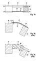
- FIGS. 7 a and 7 b show a top view and a cross section of a sixth specific embodiment of the micromechanical component.
- control element 20 includes a mirror component or a filter component 56 .
- a coil component is situated as actuator component 26 at least partially on or in a coil plate 58 .
- a spacer 60 is anchored, whose end facing away from coil plate 58 contacts an inner side 64 facing away from an incident light surface 62 of the mirror component or filter component 56 .
- control element 20 of the specific embodiment described here has a design made up of three planes 66 to 70 .
- a plane that may be designated as a drive plane 66 which is at the greatest distance from incident light surface 62 , has the coil component as actuator component 26 , the individual line strands being embedded in an insulating material 72 .
- the drive plane may have a semiconductor carrier structure 74 , on whose maximal plane, facing away from incident light surface 72 , actuator component 26 and insulating material 72 have been applied. (Semiconductor carrier structure 74 may, however, also be at least partially removed, after the application of actuator component 28 and insulating material 72 .
- Spacer 60 An intermediate plane 68 of control element 20 is formed by spacer 60 .
- Spacer 60 may have any optional size. Spacer 60 may be formed, for example, by isotropic underetching of the mirror component or the filter component.
- An optical plane 70 whose boundary surfaces are the incident light surface 62 and the inner side 64 , has the mirror component or filter component 64 .
- Inner side 64 may optionally be covered by an insulating layer 76 .
- Drive plane 68 and optical plane 70 are thus designed to be separate in this specific embodiment. The drive of the drive device thus exerts no direct force on mirror component or filter component 58 . For this reason, the drive also does not cause any deformation of mirror component or filter component 56 .
- separate springs 22 and 30 may simply be developed in both planes 66 and 70 .
- control element 20 from the three planes 68 to 70 ensures a comparatively small expansion of the control element along incident light surface 62 , since the comparatively extensive coil component is able to be applied at least partially outside/below incident light surface 62 .
- the area reduction of control element 20 that is able to be effected in this way along incident light surface 62 , is connected with cost reduction and simplifies its arrangement in a preferred application position.
- the construction of control element 20 from the three planes 66 to 70 ensures a compound lever arrangement for increasing the drive efficiency.
- the at least one vibratory spring 30 being able to be used for a desired rotation of mirror component or filter component 56 and the at least one supply line spring 22 for the electric supply line.
- the at least one supply line spring 22 may be designed to be so flexible that it exerts no, or hardly any readjusting effect on mirror component or filter component 56 , and that hardly any, or no mechanical stresses build up during an adjusting motion of mirror component or filter component 56 in the at least one supply line spring 22 .
- the material of the at least one supply line spring 22 and/or of the at least one line component 28 is thus hardly, or very little stressed by the adjusting motion of mirror component or filter component 56 .
- the at least one supply line spring 22 is preferably anchored on mounting support 24 using a first spring end 22 a and using a second spring end 22 b on coil plate 58 . All the exemplary embodiments described above may be used for the development of the at least one supply line spring 22 .
- the at least one supply line spring 22 is meander-shaped or spiral-shaped, for example.
- the at least one supply line spring 22 may also be developed as a free-standing line component 28 made of metal.
- the latter may also be embedded in an oxide and/or be provided with a support made of silicon.
- the at least one vibratory spring 30 is preferably anchored on mounting support 24 using a first spring end 30 a and using a second spring end 30 b on mirror component or filter component 56 .
- mirror component or filter component 58 is (mainly) carried by the at least one vibratory spring 30 (in a recess, or a free space of mounting support 24 ).
- the at least one vibratory spring 30 preferably specifies an axis of rotation of mirror component or filter component 56 .
- a preferred resonant frequency and/or a desired excursion direction of a rotational motion of mirror component or filter component 56 are reliably able to be established.
- An adjusting motion of incident light surface 62 of the micromechanical component is able to be triggered by supplying current to the coil component and a magnetic field B is applied/provided on the coil component.
- the field lines of magnetic field B preferably run perpendicular to a rotational axis established by the at least one vibratory spring 30 and/or parallel to incident light surface 62 .
- all the sections of the coil component have the effect of a force F, which (as a function of the direction of the current) is aligned perpendicular to incident light surface 62 .
- the coil portions that are aligned perpendicular to the axis of rotation only generate force components that are mutually compensating. Consequently, a unidirectional magnetic field B may be used to adjust the control element.
- the ability to develop the coil components and the alignment of magnetic field B are not limited to the exemplary embodiment reproduced in this instance.
- the micromechanical component described here is able to be equipped with a comparatively large coil component/coil, without this having the effect of an additional enlargement of the extension of control element 20 aligned parallel to incident light surface 62 . Consequently, the micromechanical component may be used particularly for implementing a micromirror device equipped with two mirrors, such as a projector or a scanner.
- a light beam may, for example, be deflected via a first mirror about a first axis, before it impinges upon incident light surface 62 of the micromechanical component shown in FIGS. 7 a and 7 b .
- a comparatively large incident light surface 62 of the micromechanical component is advantageous for deflecting the light beam about a second axis.
- one is able to implement a micromechanical component, whose control element 20 , in spite of its comparatively large incident light surface 62 , has a comparatively small extension parallel to incident light surface 62 , based on the development of the coil component in drive plane 66 , outside optical plane 70 .
- the advantageous specific embodiment is producible by positioning the coil component at least partially on or in a coil plate, and the coil plate, having a spacer anchored to it, is connected to a mirror component or filter component of the control element, one end of the spacer facing away from the coil plate being connected to an inner side of the mirror component or filter component facing away from an incident light surface of the mirror component or filter component; and the at least one vibratory spring being anchored by its first spring end to the mounting support and by its second spring end to the mirror component or filter component.
- FIG. 8 A partial illustration of a seventh specific embodiment of the micromechanical component is shown in FIG. 8 .
- micromechanical component shown schematically in FIG. 8 has the components already described above. As may be recognized in FIG. 8 , an advantageous contacting of actuator component 26 developed as coil component is able to be implemented via a meander-shaped metallization as line component.
- the anchoring point of the at least one supply line spring 22 on mounting support 24 developed, for example, as a drive frame is selected in such a way that bending, that is as little as possible, of the at least one supply line spring 22 during the adjusting motion of control element 20 with respect to mounting support 24 takes place.
- an anchoring point of the at least one supply line spring 22 is able to lie at a piercing point of the axis of rotation of control element 20 . Consequently, only a purely rotational stress of the at least one supply line spring 22 takes place. This avoids stressing line component 28 , that is guided via the at least one supply line spring 22 .
Landscapes
- Engineering & Computer Science (AREA)
- Microelectronics & Electronic Packaging (AREA)
- Physics & Mathematics (AREA)
- Computer Hardware Design (AREA)
- Electromagnetism (AREA)
- General Physics & Mathematics (AREA)
- Optics & Photonics (AREA)
- Micromachines (AREA)
Applications Claiming Priority (3)
| Application Number | Priority Date | Filing Date | Title |
|---|---|---|---|
| DE102012206280 | 2012-04-17 | ||
| DE102012206280.7A DE102012206280B4 (de) | 2012-04-17 | 2012-04-17 | Mikromechanisches Bauteil und Herstellungsverfahren für ein mikromechanisches Bauteil |
| DE102012206280.7 | 2012-04-17 |
Publications (2)
| Publication Number | Publication Date |
|---|---|
| US20130271807A1 US20130271807A1 (en) | 2013-10-17 |
| US9045331B2 true US9045331B2 (en) | 2015-06-02 |
Family
ID=49232262
Family Applications (1)
| Application Number | Title | Priority Date | Filing Date |
|---|---|---|---|
| US13/864,623 Active 2033-12-11 US9045331B2 (en) | 2012-04-17 | 2013-04-17 | Micromechanical component and method for producing a micromechanical component |
Country Status (2)
| Country | Link |
|---|---|
| US (1) | US9045331B2 (de) |
| DE (1) | DE102012206280B4 (de) |
Families Citing this family (2)
| Publication number | Priority date | Publication date | Assignee | Title |
|---|---|---|---|---|
| TWI580632B (zh) * | 2014-03-14 | 2017-05-01 | 財團法人工業技術研究院 | 具用於旋轉元件之摺疊彈簧的微機電裝置 |
| US10908650B1 (en) * | 2020-02-05 | 2021-02-02 | Dell Products, L.P. | Universal elastic joint for portable computer |
Citations (3)
| Publication number | Priority date | Publication date | Assignee | Title |
|---|---|---|---|---|
| EP0836265A1 (de) | 1996-04-26 | 1998-04-15 | The Nippon Signal Co. Ltd. | Elektromagnetischer betätiger und verfahren zu seiner herstellung |
| WO2005078509A2 (en) | 2004-02-09 | 2005-08-25 | Microvision, Inc. | Mems scanning system with improved performance |
| US20110007376A1 (en) * | 2008-02-04 | 2011-01-13 | Stefan Pinter | Micromechanical component and method for producing same |
Family Cites Families (2)
| Publication number | Priority date | Publication date | Assignee | Title |
|---|---|---|---|---|
| JP4247254B2 (ja) | 2006-08-08 | 2009-04-02 | マイクロプレシジョン株式会社 | 電磁駆動型光偏向素子 |
| JP5383065B2 (ja) | 2008-03-05 | 2014-01-08 | 日本信号株式会社 | プレーナ型電磁アクチュエータ及びその製造方法 |
-
2012
- 2012-04-17 DE DE102012206280.7A patent/DE102012206280B4/de active Active
-
2013
- 2013-04-17 US US13/864,623 patent/US9045331B2/en active Active
Patent Citations (3)
| Publication number | Priority date | Publication date | Assignee | Title |
|---|---|---|---|---|
| EP0836265A1 (de) | 1996-04-26 | 1998-04-15 | The Nippon Signal Co. Ltd. | Elektromagnetischer betätiger und verfahren zu seiner herstellung |
| WO2005078509A2 (en) | 2004-02-09 | 2005-08-25 | Microvision, Inc. | Mems scanning system with improved performance |
| US20110007376A1 (en) * | 2008-02-04 | 2011-01-13 | Stefan Pinter | Micromechanical component and method for producing same |
Also Published As
| Publication number | Publication date |
|---|---|
| US20130271807A1 (en) | 2013-10-17 |
| DE102012206280B4 (de) | 2023-12-21 |
| DE102012206280A1 (de) | 2013-10-17 |
Similar Documents
| Publication | Publication Date | Title |
|---|---|---|
| KR101740115B1 (ko) | 지지 구조체 및 지지 구조체를 형성하는 방법 | |
| US7061063B2 (en) | Microstructure and its fabrication method | |
| JP2005092174A (ja) | マイクロ揺動素子 | |
| CN107783280B (zh) | 扫描微机电反射器系统 | |
| US6975442B2 (en) | Resonance scanner | |
| US20070120438A1 (en) | Electrostatic control device | |
| US20050018322A1 (en) | Magnetically actuated fast MEMS mirrors and microscanners | |
| US8429809B2 (en) | Method of manufacturing a micro-electromechanical system (MEMS) device | |
| JP3942619B2 (ja) | 光偏向素子 | |
| JP5414583B2 (ja) | マイクロ構造体及びその製造方法 | |
| US7623283B2 (en) | Actuator | |
| US6677695B2 (en) | MEMS electrostatic actuators with reduced actuation voltage | |
| US20050184351A1 (en) | Mems scanning mirror with trenched surface and tapered comb teeth for reducing inertia and deformation | |
| US7218439B2 (en) | Apparatus and method for adjusting the resonant frequency of an oscillating device | |
| US20190219814A1 (en) | Micromechanical component and method for producing a micromechanical component | |
| US9045331B2 (en) | Micromechanical component and method for producing a micromechanical component | |
| KR101988699B1 (ko) | 미소기계 부품 및 미소기계 부품의 제조 방법 | |
| US7402255B2 (en) | MEMS scanning mirror with trenched surface and I-beam like cross-section for reducing inertia and deformation | |
| US9268130B2 (en) | Micromechanical component and method for producing a micromechanical component | |
| JP2006201520A (ja) | Memsミラースキャナ | |
| JP5322844B2 (ja) | プレーナ型アクチュエータ | |
| US20230194790A1 (en) | Silicon beam-steering apparatus and method for manufacturing | |
| CN113366368B (zh) | Mems反光镜装置以及其制造方法 | |
| JP2002072127A (ja) | 板バネ構造体 | |
| JP2003344786A (ja) | 静電アクチュエータ |
Legal Events
| Date | Code | Title | Description |
|---|---|---|---|
| AS | Assignment |
Owner name: ROBERT BOSCH GMBH, GERMANY Free format text: ASSIGNMENT OF ASSIGNORS INTEREST;ASSIGNORS:NITSCHE, HEIKO;PINTER, STEFAN;SCHOCK, WOLFRAM;AND OTHERS;SIGNING DATES FROM 20130614 TO 20130708;REEL/FRAME:031147/0418 |
|
| STCF | Information on status: patent grant |
Free format text: PATENTED CASE |
|
| MAFP | Maintenance fee payment |
Free format text: PAYMENT OF MAINTENANCE FEE, 4TH YEAR, LARGE ENTITY (ORIGINAL EVENT CODE: M1551); ENTITY STATUS OF PATENT OWNER: LARGE ENTITY Year of fee payment: 4 |
|
| MAFP | Maintenance fee payment |
Free format text: PAYMENT OF MAINTENANCE FEE, 8TH YEAR, LARGE ENTITY (ORIGINAL EVENT CODE: M1552); ENTITY STATUS OF PATENT OWNER: LARGE ENTITY Year of fee payment: 8 |