US9019193B2 - Method of compensating image data and display apparatus for performing the same - Google Patents
Method of compensating image data and display apparatus for performing the same Download PDFInfo
- Publication number
- US9019193B2 US9019193B2 US12/969,791 US96979110A US9019193B2 US 9019193 B2 US9019193 B2 US 9019193B2 US 96979110 A US96979110 A US 96979110A US 9019193 B2 US9019193 B2 US 9019193B2
- Authority
- US
- United States
- Prior art keywords
- temperature value
- set temperature
- compensation data
- data
- compensation
- Prior art date
- Legal status (The legal status is an assumption and is not a legal conclusion. Google has not performed a legal analysis and makes no representation as to the accuracy of the status listed.)
- Active, expires
Links
Images


Classifications
-
- G—PHYSICS
- G09—EDUCATION; CRYPTOGRAPHY; DISPLAY; ADVERTISING; SEALS
- G09G—ARRANGEMENTS OR CIRCUITS FOR CONTROL OF INDICATING DEVICES USING STATIC MEANS TO PRESENT VARIABLE INFORMATION
- G09G3/00—Control arrangements or circuits, of interest only in connection with visual indicators other than cathode-ray tubes
- G09G3/20—Control arrangements or circuits, of interest only in connection with visual indicators other than cathode-ray tubes for presentation of an assembly of a number of characters, e.g. a page, by composing the assembly by combination of individual elements arranged in a matrix no fixed position being assigned to or needed to be assigned to the individual characters or partial characters
- G09G3/34—Control arrangements or circuits, of interest only in connection with visual indicators other than cathode-ray tubes for presentation of an assembly of a number of characters, e.g. a page, by composing the assembly by combination of individual elements arranged in a matrix no fixed position being assigned to or needed to be assigned to the individual characters or partial characters by control of light from an independent source
- G09G3/36—Control arrangements or circuits, of interest only in connection with visual indicators other than cathode-ray tubes for presentation of an assembly of a number of characters, e.g. a page, by composing the assembly by combination of individual elements arranged in a matrix no fixed position being assigned to or needed to be assigned to the individual characters or partial characters by control of light from an independent source using liquid crystals
-
- G—PHYSICS
- G09—EDUCATION; CRYPTOGRAPHY; DISPLAY; ADVERTISING; SEALS
- G09G—ARRANGEMENTS OR CIRCUITS FOR CONTROL OF INDICATING DEVICES USING STATIC MEANS TO PRESENT VARIABLE INFORMATION
- G09G3/00—Control arrangements or circuits, of interest only in connection with visual indicators other than cathode-ray tubes
- G09G3/20—Control arrangements or circuits, of interest only in connection with visual indicators other than cathode-ray tubes for presentation of an assembly of a number of characters, e.g. a page, by composing the assembly by combination of individual elements arranged in a matrix no fixed position being assigned to or needed to be assigned to the individual characters or partial characters
- G09G3/34—Control arrangements or circuits, of interest only in connection with visual indicators other than cathode-ray tubes for presentation of an assembly of a number of characters, e.g. a page, by composing the assembly by combination of individual elements arranged in a matrix no fixed position being assigned to or needed to be assigned to the individual characters or partial characters by control of light from an independent source
- G09G3/36—Control arrangements or circuits, of interest only in connection with visual indicators other than cathode-ray tubes for presentation of an assembly of a number of characters, e.g. a page, by composing the assembly by combination of individual elements arranged in a matrix no fixed position being assigned to or needed to be assigned to the individual characters or partial characters by control of light from an independent source using liquid crystals
- G09G3/3611—Control of matrices with row and column drivers
- G09G3/3648—Control of matrices with row and column drivers using an active matrix
-
- G—PHYSICS
- G09—EDUCATION; CRYPTOGRAPHY; DISPLAY; ADVERTISING; SEALS
- G09G—ARRANGEMENTS OR CIRCUITS FOR CONTROL OF INDICATING DEVICES USING STATIC MEANS TO PRESENT VARIABLE INFORMATION
- G09G2320/00—Control of display operating conditions
- G09G2320/02—Improving the quality of display appearance
- G09G2320/0252—Improving the response speed
-
- G—PHYSICS
- G09—EDUCATION; CRYPTOGRAPHY; DISPLAY; ADVERTISING; SEALS
- G09G—ARRANGEMENTS OR CIRCUITS FOR CONTROL OF INDICATING DEVICES USING STATIC MEANS TO PRESENT VARIABLE INFORMATION
- G09G2320/00—Control of display operating conditions
- G09G2320/02—Improving the quality of display appearance
- G09G2320/0261—Improving the quality of display appearance in the context of movement of objects on the screen or movement of the observer relative to the screen
-
- G—PHYSICS
- G09—EDUCATION; CRYPTOGRAPHY; DISPLAY; ADVERTISING; SEALS
- G09G—ARRANGEMENTS OR CIRCUITS FOR CONTROL OF INDICATING DEVICES USING STATIC MEANS TO PRESENT VARIABLE INFORMATION
- G09G2320/00—Control of display operating conditions
- G09G2320/02—Improving the quality of display appearance
- G09G2320/0285—Improving the quality of display appearance using tables for spatial correction of display data
-
- G—PHYSICS
- G09—EDUCATION; CRYPTOGRAPHY; DISPLAY; ADVERTISING; SEALS
- G09G—ARRANGEMENTS OR CIRCUITS FOR CONTROL OF INDICATING DEVICES USING STATIC MEANS TO PRESENT VARIABLE INFORMATION
- G09G2320/00—Control of display operating conditions
- G09G2320/04—Maintaining the quality of display appearance
- G09G2320/041—Temperature compensation
-
- G—PHYSICS
- G09—EDUCATION; CRYPTOGRAPHY; DISPLAY; ADVERTISING; SEALS
- G09G—ARRANGEMENTS OR CIRCUITS FOR CONTROL OF INDICATING DEVICES USING STATIC MEANS TO PRESENT VARIABLE INFORMATION
- G09G2320/00—Control of display operating conditions
- G09G2320/06—Adjustment of display parameters
- G09G2320/0626—Adjustment of display parameters for control of overall brightness
- G09G2320/064—Adjustment of display parameters for control of overall brightness by time modulation of the brightness of the illumination source
-
- G—PHYSICS
- G09—EDUCATION; CRYPTOGRAPHY; DISPLAY; ADVERTISING; SEALS
- G09G—ARRANGEMENTS OR CIRCUITS FOR CONTROL OF INDICATING DEVICES USING STATIC MEANS TO PRESENT VARIABLE INFORMATION
- G09G2340/00—Aspects of display data processing
- G09G2340/16—Determination of a pixel data signal depending on the signal applied in the previous frame
Definitions
- Exemplary embodiments of the present invention generally relate to a method of compensating image data and a display apparatus for performing the same. More particularly, exemplary embodiments of the present invention relate to a method of compensating image data used in a liquid crystal display apparatus and a display apparatus for performing the method.
- a liquid crystal display (“LCD”) apparatus includes an LCD panel and a light source apparatus which provides the LCD panel with light.
- the LCD panel typically includes an array substrate, an opposite substrate and a liquid crystal layer interposed between the array substrate and the opposite substrate.
- the liquid crystal layer includes liquid crystal molecules which have a physical characteristic such that they may alter the polarization of light passing therethrough.
- an electric field is applied to the liquid crystal molecules, an arrangement of the liquid crystal molecules is altered, thereby also altering the orientation of their polarization directions.
- a transmittance of light is altered in accordance with the arrangement of liquid crystal molecule so that image is displayed.
- DCC dynamic capacitance compensation
- a gradation data of a current frame is greater than that of a previous frame
- the gradation data of the current frame is over driven to a higher gradation rather than the gradation data of the current frame to substantially enhance a rising response speed of the liquid crystal molecules.
- a gradation data of a current frame is smaller than that of a previous frame
- the gradation data of the current frame under driven to a lower gradation rather than the gradation data of the current frame to substantially enhance a falling response speed of the liquid crystal molecules.
- Exemplary embodiments of the present invention provide a method of compensating image data for enhancing quality of a display image.
- Exemplary embodiments of the present invention also provide a display apparatus for performing the above-mentioned method.
- a compensation data of an image data is generated in accordance with a temperature value using a compensation data generated through a look-up table (“LUT”) that is mapped corresponding to a compensation data of a previous frame and a set temperature value which is smaller than and closest to the temperature value or which is greater than and closest to the temperature value.
- LUT look-up table
- a compensation data is generated in accordance with positions of an image data using a plurality of LUTs mapped corresponding to a plurality of space areas of a display panel.
- an exemplary embodiment of a method of compensating image data In the exemplary embodiment of the method, a compensation data according to a position of an image data is generated using a plurality of LUTs mapped corresponding to a plurality of space areas of a display panel in accordance with a temperature.
- an exemplary embodiment of a display apparatus includes a display panel, a data compensating part and a data driving part.
- the display panel includes a plurality of pixels.
- the data compensating part generates a compensation data of an image data in accordance with a temperature value using a compensation data generated through an LUT that is mapped corresponding to a compensation data of a previous frame and a set temperature value which is smaller than and closest to the temperature value or which is greater than and closest to the temperature value.
- the data driving part drives the display panel using the compensation data.
- an exemplary embodiment of a display apparatus includes a display panel, a data compensating part and a data driving part.
- the display panel includes a plurality of pixels.
- the data compensating part generates a compensation data in accordance with positions of an image data using a plurality of LUTs mapped corresponding to a plurality of space areas of the display panel.
- the data driving part drives the display panel using the compensation data.
- an exemplary embodiment of a display apparatus includes a display panel, a data compensating part and a data driving part.
- the display panel includes a plurality of pixels.
- the data compensating part generates a compensation data according to a position of an image data using a plurality of LUTs mapped corresponding to a plurality of space areas of the display panel in accordance with a temperature.
- the data driving part drives the display panel using the compensation data.
- compensation data different from each other are generated in accordance with positions of a display panel, so that display quality may be substantially enhanced. Moreover, compensation data different from each other are generated in accordance with a temperature of the display panel which minutely increases or decreases, so that display quality may be substantially enhanced.
- FIG. 1 is a block diagram showing an exemplary embodiment of a display apparatus according the present invention
- FIG. 2 is a concept diagram showing an exemplary embodiment of a look-up table (“LUT”) storing part of FIG. 1 ;
- LUT look-up table
- FIG. 3 is a flowchart showing an exemplary embodiment of a driving method of a data compensating part of FIG. 1 ;
- FIG. 4 is a concept diagram showing an exemplary embodiment of a driving method of the data compensating part of FIG. 1 ;
- FIG. 5 is a perspective view illustrating another exemplary embodiment of a display apparatus according to the present invention.
- FIG. 6 is a block diagram showing an exemplary embodiment of the display apparatus of FIG. 5 ;
- FIG. 7 is a concept diagram showing an exemplary embodiment of an LUT mapped corresponding to a space area of a display panel of FIG. 6 ;
- FIGS. 8A and 8B are flowcharts showing an exemplary embodiment of an interpolation method in which a compensation data is generated by a data compensating part of FIG. 6 ;
- FIGS. 9A , 9 B, 9 C and 9 D are concept diagrams showing an exemplary embodiment of an interpolation method generating a compensation data of an image data positioned at first, fourth, tenth and twelfth boundary areas of FIG. 7 ;
- FIGS. 10A , 10 B, 10 C and 10 D are concept diagrams showing an exemplary embodiment of an interpolation method generating a compensation data of an image data positioned at an eighteenth boundary area of FIG. 7 ;
- FIG. 11 is a block diagram showing another exemplary embodiment of the data compensating part of FIG. 6 according to the present invention.
- FIG. 12 is a flowchart showing an exemplary embodiment of a method of generating a compensation data by the data compensating part of FIG. 11 .
- first, second, third etc. may be used herein to describe various elements, components, regions, layers and/or sections, these elements, components, regions, layers and/or sections should not be limited by these terms. These terms are only used to distinguish one element, component, region, layer or section from another region, layer or section. Thus, a first element, component, region, layer or section discussed below could be termed a second element, component, region, layer or section without departing from the teachings of the present invention.
- spatially relative terms such as “beneath,” “below,” “lower,” “above,” “upper” and the like, may be used herein for ease of description to describe one element or feature's relationship to another element(s) or feature(s) as illustrated in the figures. It will be understood that the spatially relative terms are intended to encompass different orientations of the device in use or operation in addition to the orientation depicted in the figures. For example, if the device in the figures is turned over, elements described as “below” or “beneath” other elements or features would then be oriented “above” the other elements or features. Thus, the exemplary term “below” can encompass both an orientation of above and below. The device may be otherwise oriented (rotated 90 degrees or at other orientations) and the spatially relative descriptors used herein interpreted accordingly.
- Example embodiments of the invention are described herein with reference to cross-sectional illustrations that are schematic illustrations of idealized example embodiments (and intermediate structures) of the present invention. As such, variations from the shapes of the illustrations as a result, for example, of manufacturing techniques and/or tolerances, are to be expected. Thus, example embodiments of the present invention should not be construed as limited to the particular shapes of regions illustrated herein but are to include deviations in shapes that result, for example, from manufacturing. For example, an implanted region illustrated as a rectangle will, typically, have rounded or curved features and/or a gradient of implant concentration at its edges rather than a binary change from implanted to non-implanted region.
- a buried region formed by implantation may result in some implantation in the region between the buried region and the surface through which the implantation takes place.
- the regions illustrated in the figures are schematic in nature and their shapes are not intended to illustrate the actual shape of a region of a device and are not intended to limit the scope of the present invention.
- FIG. 1 is a block diagram showing an exemplary embodiment of a display apparatus according to the present invention.
- FIG. 2 is a concept diagram showing an exemplary embodiment of a look-up table (“LUT”) storing part shown in FIG. 1 .
- LUT look-up table
- the display apparatus includes a display panel 110 , a timing control part 310 , a gate driving part 130 , a data compensating part 320 , a data driving part 140 and a temperature sensor 410 .
- An exemplary embodiment of the display panel 110 includes a display area DA in which a plurality of pixels P is formed and a peripheral area PA surrounding the display area DA.
- Each of the pixels P includes a pixel transistor TR connected to a data line DL and a gate line GL, a liquid crystal capacitor CLC connected to the pixel transistor TR, and a storage capacitor CST connected to the pixel transistor TR.
- the gate driving part 130 generates a gate signal which will be provided to the gate line GL and is formed at the peripheral area PA of the display panel 110 .
- the gate driving part 130 may include a plurality of circuit transistors, and the plurality of circuit transistors may be formed at substantially the same time as the pixel transistor.
- the gate driving part 130 may be connected to the display panel 110 through a tape carrier package (“TCP”) method in which the gate driving chip is mounted thereon.
- the gate driving part 130 may be mounted on the peripheral area PA of the display panel 110 through a chip on glass (“COG”) method in which a gate driving chip is directly mounted on the peripheral area PA.
- Alternative exemplary embodiments include additional alternative configurations of the gate driving part 130 .
- the timing control part 310 receives an image data d(n) of an n-th frame to provide the data compensating part 320 with a position data p(x 0 ,y 0 ) of the image data d(n).
- ‘n’ is a natural number.
- the timing control part 310 controls a driving timing of the gate driving part 130 and the data driving part 140 .
- the image data d(n) is a gray-scaled value of the n-th frame
- the position data p(x 0 ,y 0 ) is a position coordinate of a pixel corresponding to the image data d(n) positioned on the display panel 110 .
- the data compensating part 320 includes a first compensation control part 321 , an LUT storing part 328 and a data storing part 329 .
- the first control part 321 compensates the image data d(n) based on a temperature value t(n) measured by the temperature sensor 410 .
- the LUT storing part 328 stores a plurality of look-up tables LUT 1 , . . . , LUTm, LUTm+1, . . . , LUTk mapped corresponding to set temperature values T 1 , . . . , Tm, Tm+1, . . . , Tk.
- ‘m’ and ‘k’ are natural numbers.
- the LUT storing part 328 set first to eighth set temperature values T 1 to T 8 corresponding to a temperature value t measured by the temperature sensor 410 , and stores first to eighth look-up tables LUT 1 to LUT 8 mapped corresponding to the temperature values T 1 to T 8 .
- the data storing part 329 stores a compensation data compensated by the first compensation control part 321 .
- the data compensating part 329 may store a compensation data D(n ⁇ 1) of an (n ⁇ 1)-th frame previous to the n-th frame.
- the first compensation control part 321 determines a set temperature value T corresponding to the temperature value t, and the first compensation control part 321 generates a compensation data D(n) of the image data d(n) using a look-up table LUT mapped corresponding to the set temperature value T stored in the LUT storing part 328 . Specifically, the first compensation control part 321 receives the temperature value t(n) measured from a temperature sensor 410 , or alternatively measures the temperature value t(n) internally, and then selects one of the set temperature values, e.g., T 1 to T 8 , which is smaller than and closest to the measured temperature value t(n) or which is greater and closest to the measured temperature value t(n).
- the first compensation control part 321 When the set temperature value T corresponding to the temperature value t does not exist and the temperature value t is between an m-th set temperature value Tm and an (m+1)-th set temperature value Tm+1, the first compensation control part 321 generates a compensation data D(n) of the image data d(n) using a compensation data D(n ⁇ 1) of an (n ⁇ 1)-th frame stored in the data storing part 329 , a compensation data generated through an m-th look-up table LUTm mapped corresponding to an m-th set temperature value Tm, and a compensation data generated through an (m+1)-th look-up table LUTm+1 mapped corresponding to an (m+1)-th set temperature value Tm+1.
- ‘m’ is a natural number.
- the data driving part 140 converts the compensation data D(n) compensated at the data compensating part 320 into an analog data voltage, and provides the display panel 110 with the analog data voltage.
- the temperature sensor 410 may be mounted on an additional circuit board.
- the temperature sensor 410 may be mounted on the display panel 110 .
- the temperature sensor 410 may be formed on a peripheral area PA of the display panel 110 in a manufacturing process substantially identical to a manufacturing process of the pixel transistor TR formed on the display area DA.
- FIG. 3 is a flowchart showing an exemplary embodiment of a driving method of a data compensating part 320 shown in FIG. 1 .
- FIG. 4 is a concept diagram showing an exemplary embodiment of a driving method of the data compensating part 320 of FIG. 1 .
- the first compensation control part 321 receives a temperature value t(n).
- the first compensation control part 321 checks whether a set temperature value T(n) corresponding to the temperature value t(n) exists or not (step S 100 ).
- the first compensation control part 321 compensates an image data d(n) of an n-th frame received using a look-up table mapped corresponding to the set temperature value T(n) (step S 101 ).
- the first compensation control part 321 generates a compensation data D(n) of the n-th frame using a compensation data D(n ⁇ 1) stored in the data storing part 329 corresponding to the position data p(x 0 ,y 0 ) of the image data d(n).
- the first compensation control part 321 compensates the image data d(n) using a compensation data D(n ⁇ 1) of an (n ⁇ 1)-th frame corresponding to the image data d(n) (step S 310 ). That is, if the measured temperature value t(n) is not within the range of the set temperature values T(n), the first compensation control part 321 compensates the image data d(n) using a compensation data D(n ⁇ 1) of an (n ⁇ 1)-th frame corresponding to the image data d(n) (step S 310 ).
- the first compensation control part 321 may determine that the temperature value t(n) is bound by an m-th set temperature value Tm and an (m+1)-th set temperature value Tm+1 (step S 110 ).
- a compensation data D(n ⁇ 1) of an (n ⁇ 1)-th frame is a compensation data Fm generated through an m-th look-up table LUTm mapped corresponding to the m-th set temperature value Tm and the temperature value t(n) exists between the m-th set temperature value Tm and a first permissive temperature value (Tm+ ⁇ t) (step S 120 )
- the first compensation control part 321 determines a compensation data D(n) of the image data d(n) to be the compensation data Fm that is a compensation data D(n ⁇ 1) of an (n ⁇ 1)-th frame (step S 121 ).
- the first compensation control part 321 determines a compensation data D(n) of the image data d(n) to be the compensation data Fm+1 that is a compensation data D(n ⁇ 1) of an (n ⁇ 1)-th frame (step S 131 ).
- the first compensation control part 321 calculates a compensation data Da(n) of the image data d(n) using a compensation data Fm of the (n ⁇ 1)-th frame and the compensation data Fm+1 corresponding to the (m+1)-th set temperature value Tm+1 greater than and closest to the temperature value t(n) using a linear interpolation method (step S 141 ).
- the compensation data Da(n) may be calculated using a linear interpolation method as following Equation 1.
- the first compensation control part 321 calculates a compensation data Db(n) of the image data d(n) using a compensation data Fm+1 of the (n ⁇ 1)-th frame and the compensation data Fm corresponding to the m-th set temperature value Tm smaller than and closest to the temperature value t(n) using a linear interpolation method (step S 151 ).
- the compensation data Db(n) may be calculated using a linear interpolation method as following Equation 2.
- the compensation data D(n) of the image data d(n) may be employed to generate the compensation data Da(n) when a temperature value t(n) of a current frame is greater than a temperature value t(n ⁇ 1) of a previous frame, and may be employed to generate the compensation data Db(n) when the temperature value t(n) of a current frame is smaller than the temperature value t(n ⁇ 1) of the previous frame.
- the compensation data D(n) of the current frame may be generated using the compensation data Da(n) or the compensation data Db(n), respectively.
- a variation of the compensation data may be compensated with respect to a compensation data of a previous frame.
- FIG. 5 is a perspective view illustrating another exemplary embodiment of the present invention.
- an exemplary embodiment of the display apparatus includes a panel assembly 100 , a light source assembly 200 and circuit boards 301 , 302 and 303 .
- the panel assembly 100 includes a display panel 110 and a data driving part 140 .
- the display panel 110 includes a display area DA in which a plurality of pixels is formed and a peripheral area PA surrounding the display area DA.
- a gate driving part 130 which generates a gate signal to be provided to the gate line GL is formed at the peripheral area PA of the display panel 110 .
- the gate driving part 130 may include a plurality of circuit transistors, and the plurality of circuit transistors may be formed through a substantially same process with a forming process of the pixel transistor.
- the gate driving part 130 may be connected to the display panel 110 through the TCP method in which the gate driving chip is mounted thereon.
- the gate driving part 130 may be mounted on the peripheral area PA of the display panel 110 through the COG method in which the gate driving chip is directly mounted on the peripheral area PA.
- the data driving part 140 includes a TCP 141 in which a data driving chip generating a data signal provided to the data line DL is mounted, and a printed circuit board (“PCB”) 143 for connecting the TCP 141 and the circuit boards 301 , 302 and 303 .
- the data driving part 140 may be mounted on the peripheral area PA of the display panel 110 through the COG method in which the data driving chip is directly mounted on the peripheral area PA.
- the light source assembly 200 is disposed below the display panel 110 to provide the display panel 110 with light.
- the light source assembly 200 includes a light source unit 210 generating light and a light guide plate 230 guiding the light from the light source assembly 210 toward the display panel 110 .
- the light source unit 210 includes a light source generating light.
- the light source may be a lamp, a light-emitting diode, or other materials providing light, for example.
- the light source units 210 are disposed at two end portions of the display panel 110 , which are opposite to each other.
- the light source unit 210 may be disposed at a surface corresponding to a display area DA of the display panel 110 in a direct type structure of a backlight assembly. In the direct type structure, the light guide plate 230 may be omitted.
- the circuit boards 301 , 302 and 303 are disposed at a rear surface of the light source assembly 200 .
- the circuit boards 301 , 302 and 303 may be attached at a rear surface of a receiving container receiving the light source assembly 200 .
- the circuit boards 301 , 302 and 303 may include a driving circuit board 301 generating driving signals provided to the gate driving part 130 and the data driving part 140 , a light source driving circuit board 302 generating a driving signal for driving the light source unit 210 , and an image circuit board 303 processing an image signal received from an external device (not shown) into a two-dimensional (“2D”) image or a three-dimensional (“3D”) image, for example.
- the image circuit board 303 may include a temperature sensor 410 .
- the temperature sensor 410 when the display apparatus is used in a television set, the temperature sensor 410 may be mounted on the image circuit board 303 , for example. Moreover, when the display apparatus is used in an LCD module, the temperature sensor 410 may be mounted on the display panel 110 or the driving circuit board 301 . When the temperature sensor 410 is mounted on the image circuit board 303 or the driving circuit board 310 , the temperature sensor 410 may be a form of a chip. Alternatively, when the temperature sensor 410 is mounted on the display panel 110 , the temperature sensor 410 may be formed on a peripheral area PA of the display panel 110 in a manufacturing process substantially identical to a manufacturing process of the pixel transistor TR formed on the display area DA.
- the circuit boards 301 , 302 and 303 which are disposed at a rear surface of the light source assembly 200 , are resultantly disposed at a rear surface of the display panel 110 .
- a driving temperature of the circuit boards 301 , 302 and 303 a temperature of a first area of the display panel 110 on which the circuit boards 301 , 302 and 303 are disposed is greater than a temperature of a second area of the display panel 110 on which the circuit boards 301 , 302 and 303 are not disposed.
- a response speed of liquid crystal molecules of the display panel 110 is varied in accordance with temperature. That is, a liquid crystal response speed of the first area where the circuit boards 301 , 302 and 303 are disposed is different from a liquid crystal response speed of the second area where the circuit boards 301 , 302 and 303 are not disposed.
- the driving circuit board 301 may include a data compensating part generating a compensation data for compensating an image in accordance with the spatial temperature distribution of the display panel 110 .
- FIG. 6 is a block diagram showing an exemplary embodiment of the display apparatus as shown in FIG. 5 .
- the display apparatus includes a timing control part 310 , a data compensating part 320 A, the data driving part 140 and the display panel 110 .
- the timing control part 310 receives an image data d(n) to provide the data compensating part 320 A with an position data p(x 0 ,y 0 ) of the image data d(n).
- the data compensating part 320 A includes a second compensation control part 323 , an LUT storing part 328 and a data storing part 329 to generate a compensation data D(n) of the image data d(n) in accordance with positions of the display panel 110 using the image data d(n) and the position data p(x 0 ,y 0 ).
- the display panel 110 may be divided into a plurality of space areas and a plurality of boundary areas of between the space areas by a plurality of parameters.
- the display panel 110 may be divided into twelve space areas A 1 , A 2 , A 3 , . . . , A 12 and twenty-three boundary areas B 1 , B 2 , B 3 , . . . , B 23 positioned between the space areas A 1 , A 2 , A 3 , . . . , A 12 , for example.
- the x parameters and y parameters may be user setting values stored as a register value, for example, and may be set in various ways in accordance with the number of the space areas.
- the second compensation control part 323 receives a temperature value t(n), an image data d(n) and the position data p(x 0 ,y 0 ) of the image data d(n).
- the second compensation control part 323 determines a set temperature value T corresponding to the temperature value t(n).
- the second compensation control part 323 reads a plurality of LUTs from the LUT storing part 328 , which are mapped corresponding to the space areas A 1 , A 2 , A 3 , . . . , A 12 using the image data d(n), the position data p(x 0 ,y 0 ) and the set temperature value T.
- the second compensation control part 323 generates the compensation data D(n) of the image data d(n) positioned at the space areas A 1 , A 2 , A 3 , . . . , A 12 using the LUTs corresponding to the set temperature value T(n).
- the second compensation control part 323 generates an image data d(n) positioned at the boundary areas B 1 , B 2 , B 3 , . . . , B 23 using a compensation data D(n) positioned at space areas A 1 , A 2 , A 3 , . . . , A 12 adjacent to the boundary areas B 1 , B 2 , B 3 , . . . , B 23 using a linear interpolation method.
- the compensation data D(n) of the image data d(n) positioned at the boundary areas B 1 , B 2 , B 3 , . . . , B 23 may be generated to be data which are gradually varied with respect to the compensation data D(n) positioned at the adjacent space areas A 1 , A 2 , A 3 , . . . , A 12 .
- the LUT storing part 328 stores a plurality of look-up tables LUT 1 , . . . , LUTm, LUTm+1, . . . , LUTk mapped corresponding to a plurality of set temperature values T 1 , . . . , Tm, Tm+1, . . . , Tk, as shown in a manner of FIG. 2 .
- ‘m’ and ‘k’ are natural numbers.
- Equation 3 is an example showing LUT information (also referred to as “Local DCC”) mapped corresponding to a space area.
- LUT information also referred to as “Local DCC”
- Local DCC( T ) (LUT A1 ),(LUT A2 ),(LUT A3 ), . . . , (LUT A12 )
- a first look-up table LUTA 1 is mapped corresponding to a first space area A 1
- a second look-up table LUTA 2 is mapped corresponding to a second space area A 2
- a third look-up table LUTA 3 is mapped corresponding to a third space area A 3 in accordance with the set temperature value T.
- a twelfth look-up table LUTA 12 is mapped corresponding to a twelfth space area A 12 in accordance with the set temperature value T.
- the Local DCC may be stored in a register, and the second compensation control part 323 may use LUTs mapped corresponding to set temperature values which are stored in the LUT storing part 328 using the Local DCC.
- the LUT storing part 328 may store LUTs mapped corresponding to the space areas in accordance with a set temperature value T as shown in Equation 3.
- the data storing part 329 stores a compensation data D(n) generated for the second compensation control part 323 .
- the second compensation control part 323 may use a compensation data of the n-th frame.
- FIG. 7 is a concept diagram showing the exemplary embodiment of the look-up table mapped corresponding to a space area of a display panel as shown in FIG. 6 .
- the compensation control part 323 reads a set temperature value T stored in the LUT storing part 329 and twelve look-up tables LUT 2 , LUT 4 , LUT 2 , LUT 1 , LUT 3 , LUT 5 , LUT 3 , LUT 2 , LUT 1 , LUT 2 , LUT 2 and LUT 1 for twelve space areas A 1 , A 2 , A 3 , . . . , A 12 mapped at a temperature of about 10° C.
- the second compensation control part 323 generates the compensation data D(n) of the image data d(n) using twelve look-up tables LUT 2 , LUT 4 , LUT 2 , LUT 1 , LUT 3 , LUT 5 , LUT 3 , LUT 2 , LUT 1 , LUT 2 , LUT 2 and LUT 1 mapped corresponding to the space areas A 1 , A 2 , A 3 , . . . , A 12 .
- the second compensation control part 323 generates a compensation data D(n) of an image data d(n) positioned at the boundary areas B 1 , B 2 , B 3 , . . . , B 23 using a linear interpolation method with the compensation data D(n) of the image data d(n) positioned at adjacent space areas A 1 , A 2 , A 3 , . . . , A 12 .
- FIGS. 8A and 8B are flowcharts showing an exemplary embodiment of an interpolation method in which a compensation data is generated by a data compensating part as shown in FIG. 6 .
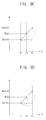
- FIGS. 9A , 9 B, 9 C and 9 D are concept diagrams showing the exemplary embodiment of an interpolation method generating a compensation data of an image data positioned at first, fourth, tenth and twelfth boundary areas, respectively, as shown in FIG. 7 .
- FIGS. 10A , 10 B, 10 C and 10 D are concept diagrams showing an interpolation method generating a compensation data of an image data positioned at an eighteenth boundary area as shown in FIG. 7 .
- the second compensation control part 323 receives a temperature value t(n), an image data d(n) and the position data p(x 0 ,y 0 ) of the image data d(n).
- the second compensation control part 323 reads look-up tables LUT 2 , LUT 4 , LUT 2 , LUT 1 , LUT 3 , LUT 5 , LUT 3 , LUT 2 , LUT 1 , LUT 2 , LUT 2 and LUT 1 mapped corresponding to the space areas A 1 to A 12 with respect to the set temperature value T(n) corresponding to the temperature value t(n) (step S 201 ).
- the second compensation control part 323 When the position data p(x 0 ,y 0 ) is positioned at the second space area A 1 (x 0 ⁇ x 1 and y 0 ⁇ y 1 ) (step S 211 ), the second compensation control part 323 generates the compensation data D(n) using a second look-up table LUT 2 mapped corresponding to the first space area A 1 (step S 212 ).
- the second compensation control part 323 When the position data p(x 0 ,y 0 ) is positioned at the second space area A 2 (x 0 ⁇ x 2 and y 0 ⁇ y 1 ) (step S 221 ), the second compensation control part 323 generates the compensation data D(n) using a fourth look-up table LUT 4 mapped corresponding to the second space area A 2 (step S 222 ).
- the second compensation control part 323 When the position data p(x 0 ,y 0 ) is positioned at the fifth space area A 5 (x 0 ⁇ x 1 and y 0 ⁇ y 2 ) (step S 231 ), the second compensation control part 323 generates the compensation data D(n) using a third look-up table LUT 3 mapped corresponding to the fifth space area A 5 (step S 232 ).
- the second compensation control part 323 When the position data p(x 0 ,y 0 ) is positioned at the sixth space area A 6 (x 0 ⁇ x 2 and y 0 ⁇ y 2 ) (step S 241 ), the second compensation control part 323 generates the compensation data D(n) using a fifth look-up table LUT 5 mapped corresponding to the sixth space area A 6 (step S 242 ).
- the second compensation control part 323 uses a similar method to generate compensation data D(n) of image data d(n) positioned at other remaining space areas.
- the second compensation control part 323 when it is determined that the image data d(n) is positioned at a first boundary area B 1 between the first and second space areas A 1 and A 2 (step S 251 ), the second compensation control part 323 generates a compensation data D(n) of the image data d(n) positioned at the first boundary area B 1 using a compensation data DA 1 ( n ) of an image data positioned at a first space area A 1 and a compensation data DA 2 ( n ) of an image data positioned at a second space area A 2 using a linear interpolation method (step S 252 ).
- the second compensation control part 323 may calculate the compensation data D(n) of the image data d(n) using a linear interpolation method such as the following Equation 4.
- the compensation data DA 1 ( n ) is generated by a second look-up table LUT 2
- the compensation data DA 2 ( n ) is generated by a fourth look-up table LUT 4 .
- the second compensation control part 323 may calculate a compensation data D(n) of the image data d(n) using the compensation data DA 5 ( n ) of the image data positioned at the fifth space area A 5 and the compensation data DA 6 ( n ) of the image data positioned at the sixth space area A 6 using a linear interpolation method such as the following Equation 5 (step S 262 ).
- D ⁇ ( n ) D A5 ⁇ ( n ) + ( x ⁇ ⁇ 0 - x ⁇ ⁇ 1 ) ( x ⁇ ⁇ 2 - x ⁇ ⁇ 1 ) ⁇ ( D A ⁇ ⁇ 6 ⁇ ( n ) - D A ⁇ ⁇ 5 ⁇ ( n ) ) ⁇ Equation ⁇ ⁇ 5 ⁇
- the compensation data DA 5 ( n ) is generated by a third look-up table LUT 3
- the compensation data DA 6 ( n ) is generated by a fifth look-up table LUT 5 .
- the second compensation control part 323 may calculate a compensation data D(n) of the image data d(n) using the compensation data DA 1 ( n ) of the image data positioned at the first space area A 1 and the compensation data DA 5 ( n ) of the image data positioned at the fifth space area A 5 using a linear interpolation method such as the following Equation 6 (step S 272 ).
- D ⁇ ( n ) D A ⁇ ⁇ 1 ⁇ ( n ) + ( y ⁇ ⁇ 0 - y ⁇ ⁇ 1 ) ( y ⁇ ⁇ 2 - y ⁇ ⁇ 1 ) ⁇ ( D A ⁇ ⁇ 5 ⁇ ( n ) - D A ⁇ ⁇ 1 ⁇ ( n ) ) ⁇ Equation ⁇ ⁇ 6 ⁇
- the compensation data DA 1 ( n ) is generated by a second look-up table LUT 2
- the compensation data DA 5 ( n ) is generated by a third look-up table LUT 3 .
- the second compensation control part 323 may calculate a compensation data D(n) of the image data d(n) using the compensation data DA 2 ( n ) of the image data positioned at the second space area A 2 and the compensation data DA 6 ( n ) of the image data positioned at the sixth space area A 6 using a linear interpolation method such as the following Equation 7 (step S 282 ).
- D ⁇ ( n ) D A ⁇ ⁇ 2 ⁇ ( n ) + ( y ⁇ ⁇ 0 - y ⁇ ⁇ 1 ) ( y ⁇ ⁇ 2 - y ⁇ ⁇ 1 ) ⁇ ( D A ⁇ ⁇ 6 ⁇ ( n ) - D A ⁇ ⁇ 2 ⁇ ( n ) ) ⁇ Equation ⁇ ⁇ 7 ⁇
- the compensation data DA 2 ( n ) is generated by a fourth look-up table LUT 4 and the compensation data DA 6 ( n ) is generated by a fifth look-up table LUT 5 .
- the second compensation control part 323 may calculate a compensation data of an image data positioned at the boundary area using a linear interpolation method with two compensation data corresponding to the two space areas.
- the second compensation control part 323 may calculate a compensation data D(n) of the image data d(n) using a compensation data DA 1 ( n ) of the image data positioned at the first space area A 1 , a compensation data DA 2 ( n ) of the image data positioned at the second space area A 2 , a compensation data DA 5 ( n ) of the image data positioned at the fifth space area A 5 , and the compensation data DA 6 ( n ) of the image data positioned at the sixth space area A 6 using a linear interpolation method (step S 292 ).
- the second compensation control part 323 may calculate a compensation data DI(n) when the position data is y 0 ⁇ y 1 using the compensation data DA 1 ( n ) of the image data positioned at the first space area A 1 and the compensation data DA 2 ( n ) of the image data positioned at the second space area A 2 using a linear interpolation method such as the following Equation 8.
- D I ⁇ ( n ) D A ⁇ ⁇ 1 ⁇ ( n ) + ( x ⁇ ⁇ 0 - x ⁇ ⁇ 1 ) ( x ⁇ ⁇ 2 - x ⁇ ⁇ 1 ) ⁇ ( D A ⁇ ⁇ 2 ⁇ ( n ) - D A ⁇ ⁇ 1 ⁇ ( n ) ) ⁇ Equation ⁇ ⁇ 8 ⁇
- the second compensation control part 323 may calculate a compensation data DJ(n) when the position data is y 2 ⁇ y 0 ⁇ y 3 using the compensation data DA 5 ( n ) of the image data positioned at the fifth space area A 5 and the compensation data DA 6 ( n ) of the image data positioned at the sixth space area A 6 using a linear interpolation method such as the following Equation 9.
- D J ⁇ ( n ) D A ⁇ ⁇ 5 ⁇ ( n ) + ( x ⁇ ⁇ 0 - x ⁇ ⁇ 1 ) ( x ⁇ ⁇ 2 - x ⁇ ⁇ 1 ) ⁇ ( D A ⁇ ⁇ 6 ⁇ ( n ) - D A ⁇ ⁇ 5 ⁇ ( n ) ) ⁇ Equation ⁇ ⁇ 9 ⁇
- the second compensation control part 323 may calculate a compensation data D(n) of the image data d(n) using the compensation data DI(n) and the compensation data DJ(n) using a linear interpolation method such as the following Equation 10.
- the second compensation control part 323 may calculate a compensation data D(n) of the image data d(n) using a linear interpolation method with four compensation data corresponding to the four space areas.
- the second compensation control part 323 may generate compensation data of the image data, when the image data are positioned at twelve space areas and twenty-three boundary areas.
- compensation data of an image data are generated in accordance with a temperature distribution corresponding to a position of the display panel 110 , so that display defects due to a temperature deviation of the display panel 110 may be substantially prevented.
- FIG. 11 is a block diagram showing another exemplary embodiment of a data compensating part according to the present invention.
- FIG. 12 is a flowchart showing an exemplary embodiment of a method of generating a compensation data by the data compensating part of FIG. 11 .
- an exemplary embodiment of the display apparatus includes a data compensating part 320 B.
- the data compensating part 320 B includes a third compensation control part 325 , an LUT storing part 328 and a data storing part 329 .
- the third compensation control part 325 receives an image data d(n) of a current frame, a position data p(x 0 ,y 0 ) of the image data d(n) and a temperature value t(n).
- the third compensation control part 325 adaptively generates a compensation data D(n) of the image data d(n) to a fine temperature variation according to a time and a temperature variation according to a position of the display panel 110 , using the image data d(n), the position data p(x 0 ,y 0 ) and the temperature value t(n).
- the third compensation control part 325 checks whether or not the temperature value t(n) exists in plural set temperature values T 1 , . . . , Tm, Tm+1, . . . , Tk (step S 301 ).
- the third compensation control part 325 When it is determined that the temperature values t(n) exists in the set temperature values T 1 , . . . , Tm, Tm+1, . . . , Tk, the third compensation control part 325 generates the compensation data D(n) using plural look-up tables mapped corresponding to a plurality of space areas A 1 , A 2 , A 3 , . . . , A 12 which are set to a set temperature values T corresponding to the temperature value t(n) in a method explained FIGS. 8A and 8B (step S 320 ).
- the third compensation control part 325 When it is determined that the temperature values t(n) does not exist in the set temperature values T 1 , . . . , Tm, Tm+1, . . . , Tk, the third compensation control part 325 generates a compensation data D(n) using an (n ⁇ 1)-th frame data D(n ⁇ 1) stored in the data storing part 329 , a compensation data Fm generated based on an m-th set temperature value Tm smaller and closest to the temperature value t(n), and a compensation data Fm+1 generated based on an (m+1)-th set temperature value Tm+1 greater than and closest to the temperature value t(n) (step S 310 ).
- a first look-up table LUT 1 is mapped at an m-th set temperature value Tm and a second look-up table LUT 2 is mapped at an (m+1)-th set temperature value Tm+1, with respect to a first space area A 1 of FIG. 6 .
- the third compensation control part 325 When a temperature value t(n) exists between an m-th set temperature value Tm and a first permissive temperature value (Tm+ ⁇ t) and an (n ⁇ 1)-th frame data D(n ⁇ 1) stored in the data storing part 329 is generated through the first look-up table LUT 1 of the m-th set temperature value Tm, the third compensation control part 325 generates an (n ⁇ 1)-th frame data D(n ⁇ 1) stored on the data storing part 329 to be a compensation data D(n) of the image data d(n) (step S 120 and step S 121 of FIG. 3 ).
- the third compensation control part 325 generates the compensation data D(n) using a linear interpolation method with a compensation data generated through an (n ⁇ 1)-th frame data D(n ⁇ 1) and a second look-up table LUT 2 of the (m+1)-th set temperature value Tm+1 (step S 140 and step S 141 of FIG. 3 ).
- the third compensation control part 325 generates the (n ⁇ 1)-th frame data D(n ⁇ 1) stored in the data storing part 329 to be a compensation data D(n) of the image data d(n) (step S 130 and step S 131 of FIG. 3 ).
- the third compensation control part 325 generates the compensation data D(n) using a linear interpolation method with a compensation data generated through an (n ⁇ 1)-th frame data D(n ⁇ 1) and a compensation data generated through a first look-up table LUT 1 of the m-th set temperature value Tm (step S 150 and step S 151 of FIG. 3 ).
- compensation data D(n) of image data d(n) positioned at one of the space areas or the boundary areas of the display panel 110 of FIG. 6 is generated.
- a compensation data is generated in accordance with a temperature by a position of the display panel 110 , so that display defects according to a temperature deviation of the display panel 110 may be substantially prevented.
- a linear interpolation method is adapted at a boundary area of the space areas in which two look-up tables are employed, so that display defects which are viewed due to crosstalk that is suddenly generated may be substantially prevented.
- a variation of the compensation data may be gradually compensated with respect to a compensation data of a previous frame.
Landscapes
- Engineering & Computer Science (AREA)
- Physics & Mathematics (AREA)
- Computer Hardware Design (AREA)
- General Physics & Mathematics (AREA)
- Theoretical Computer Science (AREA)
- Chemical & Material Sciences (AREA)
- Crystallography & Structural Chemistry (AREA)
- Control Of Indicators Other Than Cathode Ray Tubes (AREA)
- Liquid Crystal Display Device Control (AREA)
- Liquid Crystal (AREA)
Priority Applications (1)
| Application Number | Priority Date | Filing Date | Title |
|---|---|---|---|
| US14/107,551 US9318036B2 (en) | 2010-05-11 | 2013-12-16 | Method of compensating image data and display apparatus for performing the same |
Applications Claiming Priority (3)
| Application Number | Priority Date | Filing Date | Title |
|---|---|---|---|
| KR1020100043724A KR101710577B1 (ko) | 2010-05-11 | 2010-05-11 | 데이터 보상 방법 및 이를 수행하기 위한 표시 장치 |
| KR10-2010-0043724 | 2010-05-11 | ||
| KR2010-0043724 | 2010-05-11 |
Related Child Applications (1)
| Application Number | Title | Priority Date | Filing Date |
|---|---|---|---|
| US14/107,551 Continuation US9318036B2 (en) | 2010-05-11 | 2013-12-16 | Method of compensating image data and display apparatus for performing the same |
Publications (2)
| Publication Number | Publication Date |
|---|---|
| US20110279466A1 US20110279466A1 (en) | 2011-11-17 |
| US9019193B2 true US9019193B2 (en) | 2015-04-28 |
Family
ID=43984033
Family Applications (2)
| Application Number | Title | Priority Date | Filing Date |
|---|---|---|---|
| US12/969,791 Active 2032-07-23 US9019193B2 (en) | 2010-05-11 | 2010-12-16 | Method of compensating image data and display apparatus for performing the same |
| US14/107,551 Active 2031-06-21 US9318036B2 (en) | 2010-05-11 | 2013-12-16 | Method of compensating image data and display apparatus for performing the same |
Family Applications After (1)
| Application Number | Title | Priority Date | Filing Date |
|---|---|---|---|
| US14/107,551 Active 2031-06-21 US9318036B2 (en) | 2010-05-11 | 2013-12-16 | Method of compensating image data and display apparatus for performing the same |
Country Status (5)
| Country | Link |
|---|---|
| US (2) | US9019193B2 (enExample) |
| EP (2) | EP2387027A1 (enExample) |
| JP (2) | JP5766460B2 (enExample) |
| KR (1) | KR101710577B1 (enExample) |
| CN (1) | CN102243848B (enExample) |
Cited By (1)
| Publication number | Priority date | Publication date | Assignee | Title |
|---|---|---|---|---|
| US20220208065A1 (en) * | 2019-05-09 | 2022-06-30 | Mitsubishi Electric Corporation | Image processing device, method, image display device, and recording medium |
Families Citing this family (24)
| Publication number | Priority date | Publication date | Assignee | Title |
|---|---|---|---|---|
| KR101773419B1 (ko) * | 2010-11-22 | 2017-09-01 | 삼성디스플레이 주식회사 | 데이터 보상 방법 및 이를 수행하는 표시 장치 |
| KR101860083B1 (ko) | 2011-06-29 | 2018-05-23 | 삼성디스플레이 주식회사 | 입체 영상 표시 장치 및 그 구동 방법 |
| KR102006251B1 (ko) | 2011-11-15 | 2019-10-02 | 삼성디스플레이 주식회사 | 액정 표시 장치 |
| EP2642475B1 (en) * | 2012-03-21 | 2018-07-11 | Sony Mobile Communications Inc. | Method of temperature compensation for a display panel of a portable electronic device |
| KR20130120599A (ko) * | 2012-04-26 | 2013-11-05 | 엘지전자 주식회사 | 이동 단말기 및 그 제어방법 |
| KR102104333B1 (ko) | 2013-05-28 | 2020-04-27 | 삼성디스플레이 주식회사 | 입체 영상 표시 장치 |
| KR102063313B1 (ko) | 2013-07-08 | 2020-03-03 | 삼성디스플레이 주식회사 | 표시 장치 및 그 구동 방법 |
| KR102169870B1 (ko) | 2013-12-23 | 2020-10-27 | 삼성디스플레이 주식회사 | 영상 처리 컨트롤러, 표시 장치 및 그것의 구동 방법 |
| KR102214032B1 (ko) * | 2014-07-02 | 2021-02-10 | 삼성디스플레이 주식회사 | 표시장치 |
| KR102264815B1 (ko) * | 2014-08-28 | 2021-06-15 | 삼성디스플레이 주식회사 | 표시 패널의 구동 방법, 이를 수행하기 위한 타이밍 컨트롤러 및 이 타이밍 컨트롤러를 포함하는 표시 장치 |
| CN104835467B (zh) * | 2015-05-21 | 2017-04-05 | 京东方科技集团股份有限公司 | 一种驱动方法及其装置、显示设备 |
| KR102261962B1 (ko) * | 2015-07-21 | 2021-06-07 | 삼성전자주식회사 | 디스플레이 구동 장치, 이를 포함하는 디스플레이 장치 및 시스템 |
| CN107293262B (zh) * | 2016-03-31 | 2019-10-18 | 上海和辉光电有限公司 | 用于驱动显示屏的控制方法、控制装置及显示装置 |
| KR102654711B1 (ko) * | 2016-12-05 | 2024-04-05 | 삼성디스플레이 주식회사 | 표시 장치 및 이의 구동 방법 |
| KR102421443B1 (ko) * | 2017-11-13 | 2022-07-18 | 삼성디스플레이 주식회사 | 표시 장치 및 이의 구동 방법 |
| CN108831380A (zh) * | 2018-06-11 | 2018-11-16 | 深圳市华星光电半导体显示技术有限公司 | Oled面板温度补偿系统及oled面板温度补偿方法 |
| KR20200000857A (ko) * | 2018-06-25 | 2020-01-06 | 삼성디스플레이 주식회사 | 액정 표시 장치 및 이의 구동 방법 |
| JP7379194B2 (ja) * | 2020-02-05 | 2023-11-14 | ラピスセミコンダクタ株式会社 | 表示装置及びソースドライバ |
| CN114120484A (zh) * | 2020-08-31 | 2022-03-01 | 比亚迪股份有限公司 | 一种面部识别系统及车辆 |
| CN114495849A (zh) * | 2020-10-23 | 2022-05-13 | 华硕电脑股份有限公司 | 电子装置及其显示影像补偿方法 |
| CN112767893B (zh) * | 2021-02-22 | 2023-03-07 | 重庆京东方光电科技有限公司 | 显示驱动电路及其控制方法、显示装置 |
| KR102833609B1 (ko) * | 2021-12-13 | 2025-07-15 | 삼성디스플레이 주식회사 | 표시 장치, 온도 예측부, 및 표시 장치의 구동 방법 |
| KR20240015197A (ko) * | 2022-07-26 | 2024-02-05 | 삼성디스플레이 주식회사 | 구동 제어부 및 이를 포함하는 표시 장치 |
| KR20250168910A (ko) * | 2024-05-24 | 2025-12-02 | 삼성전자주식회사 | 디스플레이 장치 및 디스플레이 장치의 다중화 구동 방법 |
Citations (16)
| Publication number | Priority date | Publication date | Assignee | Title |
|---|---|---|---|---|
| JP2001331154A (ja) | 2000-05-23 | 2001-11-30 | Matsushita Electric Ind Co Ltd | 液晶表示装置および液晶表示方法 |
| US20030098839A1 (en) | 2001-11-26 | 2003-05-29 | Lee Baek-Woon | Liquid crystal display and a driving method thereof |
| WO2003098588A1 (en) | 2002-05-17 | 2003-11-27 | Sharp Kabushiki Kaisha | Liquid crystal display device |
| EP1521237A2 (en) | 2003-09-30 | 2005-04-06 | Sharp Kabushiki Kaisha | System for displaying images on a display |
| KR20050047626A (ko) | 2003-11-18 | 2005-05-23 | 주식회사 대우일렉트로닉스 | 플라즈마 디스플레이 패널 글래스 균열 방지 방법 |
| JP2006065294A (ja) | 2004-07-28 | 2006-03-09 | Sharp Corp | 液晶表示装置およびその駆動方法 |
| US20060181503A1 (en) | 2005-02-17 | 2006-08-17 | Sharp Laboratories Of America, Inc. | Black point insertion |
| KR100672654B1 (ko) | 2004-06-30 | 2007-01-24 | 엘지.필립스 엘시디 주식회사 | 액정표시장치의 감마 전압 발생 장치 |
| CN1906656A (zh) | 2004-01-16 | 2007-01-31 | 夏普株式会社 | 液晶显示装置和液晶显示装置的信号处理装置及其程序和记录媒体以及液晶显示控制方法 |
| US20070075951A1 (en) | 2005-09-22 | 2007-04-05 | Hung-Yu Lin | Flat panel display |
| KR20080001135A (ko) | 2006-06-29 | 2008-01-03 | 엘지.필립스 엘시디 주식회사 | 액정표시장치 및 그의 구동방법 |
| EP1879173A1 (en) | 2006-07-11 | 2008-01-16 | Hannstar Display Corporation | Liquid crystal display and over driving method thereof |
| US7382383B2 (en) * | 2003-04-02 | 2008-06-03 | Sharp Kabushiki Kaisha | Driving device of image display device, program and storage medium thereof, image display device, and television receiver |
| KR20080072435A (ko) | 2007-02-02 | 2008-08-06 | 엘지디스플레이 주식회사 | 액정표시장치의 구동회로 |
| US20080284775A1 (en) | 2007-05-17 | 2008-11-20 | Yuhren Shen | Liquid crystal display driving system and method for driving the same |
| US7688304B2 (en) * | 2004-10-29 | 2010-03-30 | Samsung Electronics Co., Ltd. | Liquid crystal display device and method of modifying image signals for the same |
Family Cites Families (6)
| Publication number | Priority date | Publication date | Assignee | Title |
|---|---|---|---|---|
| JP2004151672A (ja) * | 2002-09-04 | 2004-05-27 | Sharp Corp | 液晶表示装置 |
| JP2006018130A (ja) * | 2004-07-05 | 2006-01-19 | Sony Corp | 焼き付き補正装置、表示装置、画像処理装置及びプログラム |
| JP4805701B2 (ja) * | 2006-03-17 | 2011-11-02 | シチズンホールディングス株式会社 | 液晶装置 |
| JP2008039868A (ja) * | 2006-08-02 | 2008-02-21 | Victor Co Of Japan Ltd | 液晶表示装置 |
| JP5078809B2 (ja) * | 2008-09-05 | 2012-11-21 | シャープ株式会社 | 液晶表示装置 |
| JP2010072103A (ja) * | 2008-09-16 | 2010-04-02 | Sharp Corp | 画像表示装置、画像表示方法、画像表示処理プログラム及び画像表示処理プログラムを記録したコンピュータ読み取り可能な記録媒体 |
-
2010
- 2010-05-11 KR KR1020100043724A patent/KR101710577B1/ko active Active
- 2010-12-16 US US12/969,791 patent/US9019193B2/en active Active
-
2011
- 2011-02-04 EP EP20110000919 patent/EP2387027A1/en not_active Ceased
- 2011-02-04 EP EP15188453.3A patent/EP2985757A1/en not_active Ceased
- 2011-02-17 JP JP2011032066A patent/JP5766460B2/ja active Active
- 2011-05-11 CN CN201110128003.XA patent/CN102243848B/zh active Active
-
2013
- 2013-12-16 US US14/107,551 patent/US9318036B2/en active Active
-
2015
- 2015-06-17 JP JP2015121719A patent/JP6104987B2/ja active Active
Patent Citations (16)
| Publication number | Priority date | Publication date | Assignee | Title |
|---|---|---|---|---|
| JP2001331154A (ja) | 2000-05-23 | 2001-11-30 | Matsushita Electric Ind Co Ltd | 液晶表示装置および液晶表示方法 |
| US20030098839A1 (en) | 2001-11-26 | 2003-05-29 | Lee Baek-Woon | Liquid crystal display and a driving method thereof |
| WO2003098588A1 (en) | 2002-05-17 | 2003-11-27 | Sharp Kabushiki Kaisha | Liquid crystal display device |
| US7382383B2 (en) * | 2003-04-02 | 2008-06-03 | Sharp Kabushiki Kaisha | Driving device of image display device, program and storage medium thereof, image display device, and television receiver |
| EP1521237A2 (en) | 2003-09-30 | 2005-04-06 | Sharp Kabushiki Kaisha | System for displaying images on a display |
| KR20050047626A (ko) | 2003-11-18 | 2005-05-23 | 주식회사 대우일렉트로닉스 | 플라즈마 디스플레이 패널 글래스 균열 방지 방법 |
| CN1906656A (zh) | 2004-01-16 | 2007-01-31 | 夏普株式会社 | 液晶显示装置和液晶显示装置的信号处理装置及其程序和记录媒体以及液晶显示控制方法 |
| KR100672654B1 (ko) | 2004-06-30 | 2007-01-24 | 엘지.필립스 엘시디 주식회사 | 액정표시장치의 감마 전압 발생 장치 |
| JP2006065294A (ja) | 2004-07-28 | 2006-03-09 | Sharp Corp | 液晶表示装置およびその駆動方法 |
| US7688304B2 (en) * | 2004-10-29 | 2010-03-30 | Samsung Electronics Co., Ltd. | Liquid crystal display device and method of modifying image signals for the same |
| US20060181503A1 (en) | 2005-02-17 | 2006-08-17 | Sharp Laboratories Of America, Inc. | Black point insertion |
| US20070075951A1 (en) | 2005-09-22 | 2007-04-05 | Hung-Yu Lin | Flat panel display |
| KR20080001135A (ko) | 2006-06-29 | 2008-01-03 | 엘지.필립스 엘시디 주식회사 | 액정표시장치 및 그의 구동방법 |
| EP1879173A1 (en) | 2006-07-11 | 2008-01-16 | Hannstar Display Corporation | Liquid crystal display and over driving method thereof |
| KR20080072435A (ko) | 2007-02-02 | 2008-08-06 | 엘지디스플레이 주식회사 | 액정표시장치의 구동회로 |
| US20080284775A1 (en) | 2007-05-17 | 2008-11-20 | Yuhren Shen | Liquid crystal display driving system and method for driving the same |
Non-Patent Citations (3)
| Title |
|---|
| European Office Action for Application No. 11 000 919.8-2205 dated Aug. 13, 2012. |
| Extended European Search Report for Application No. 11000919.8-2205 dated Sep. 1, 2011. |
| Partial European Search Report for Application No. 11000919.8-2205 dated Jun. 20, 2011. |
Cited By (1)
| Publication number | Priority date | Publication date | Assignee | Title |
|---|---|---|---|---|
| US20220208065A1 (en) * | 2019-05-09 | 2022-06-30 | Mitsubishi Electric Corporation | Image processing device, method, image display device, and recording medium |
Also Published As
| Publication number | Publication date |
|---|---|
| CN102243848A (zh) | 2011-11-16 |
| KR101710577B1 (ko) | 2017-02-28 |
| US9318036B2 (en) | 2016-04-19 |
| JP2011237765A (ja) | 2011-11-24 |
| CN102243848B (zh) | 2016-04-13 |
| US20140104265A1 (en) | 2014-04-17 |
| JP2015194764A (ja) | 2015-11-05 |
| KR20110124390A (ko) | 2011-11-17 |
| JP5766460B2 (ja) | 2015-08-19 |
| US20110279466A1 (en) | 2011-11-17 |
| EP2985757A1 (en) | 2016-02-17 |
| JP6104987B2 (ja) | 2017-03-29 |
| EP2387027A1 (en) | 2011-11-16 |
Similar Documents
| Publication | Publication Date | Title |
|---|---|---|
| US9019193B2 (en) | Method of compensating image data and display apparatus for performing the same | |
| US8797366B2 (en) | Method of driving a light source, light source apparatus for performing the method and display apparatus having the light source apparatus | |
| US8068086B2 (en) | Gamma-reference-voltage generating circuit and apparatus for generating gamma-voltages and display device having the circuit | |
| US9805671B2 (en) | Curved display and a driving method thereof | |
| US20080273000A1 (en) | Method of preventing flicker, circuit for performing the method, and display apparatus having the circuit | |
| US8411005B2 (en) | Liquid crystal display apparatus and driving method therefor | |
| US8031147B2 (en) | Display apparatus, and method and apparatus for driving the same | |
| US9927871B2 (en) | Image processing method, image processing circuit, and display device using the same | |
| US20080284700A1 (en) | Liquid crystal display device | |
| CN102301273A (zh) | 显示装置和显示方法 | |
| US20100156948A1 (en) | Timing controller and display device including the same | |
| US20150248865A1 (en) | Display apparatus | |
| US20080079675A1 (en) | Driving device for display device and image signal compensating method therefor | |
| US20120169780A1 (en) | Method of compensating data, data compensating apparatus for performing the method and display apparatus having the compensating apparatus | |
| KR101644189B1 (ko) | 액정표시장치 및 그의 디밍 제어방법 | |
| US8395610B2 (en) | Driving chip, driving chip package having the same, display apparatus having the driving chip, and method thereof | |
| EP2725414A1 (en) | Display device | |
| KR20170038338A (ko) | 표시장치 | |
| US20130307886A1 (en) | Apparatus for driving a display panel with compensation for heat caused by proximity to light source, and method thereof | |
| US11830447B2 (en) | Liquid crystal display drive device and method of driving the same, and image processor | |
| CN103236239B (zh) | 显示方法及应用于该显示方法的显示系统 | |
| KR101615757B1 (ko) | 액정표시장치와 그 과구동 보상방법 | |
| US20070290984A1 (en) | Liquid crystal display and control method of the same | |
| CN109326262B (zh) | 一种显示面板的驱动方法和驱动电路 | |
| KR20110072116A (ko) | 액정 표시장치 및 그의 구동방법 |
Legal Events
| Date | Code | Title | Description |
|---|---|---|---|
| AS | Assignment |
Owner name: SAMSUNG ELECTRONICS CO., LTD., KOREA, REPUBLIC OF Free format text: ASSIGNMENT OF ASSIGNORS INTEREST;ASSIGNORS:PARK, BONG-IM;LEE, JUN-PYO;AHN, IK-HUYN;AND OTHERS;REEL/FRAME:025509/0873 Effective date: 20100803 |
|
| AS | Assignment |
Owner name: SAMSUNG ELECTRONICS CO., LTD., KOREA, REPUBLIC OF Free format text: CORRECTIVE ASSIGNMENT TO CORRECT THE INCORRECT SPELLING OF INVENTOR IK-HYUN AHN'S NAME PREVIOUSLY RECORDED ON REEL 025509 FRAME 0873. ASSIGNOR(S) HEREBY CONFIRMS THE CORRECT SPELLING IS IK-HYUN AHN.;ASSIGNORS:PARK, BONG-IM;LEE, JUN-PYO;AHN, IK-HYUN;AND OTHERS;REEL/FRAME:025946/0898 Effective date: 20110221 |
|
| AS | Assignment |
Owner name: SAMSUNG DISPLAY CO., LTD., KOREA, REPUBLIC OF Free format text: ASSIGNMENT OF ASSIGNORS INTEREST;ASSIGNOR:SAMSUNG ELECTRONICS CO., LTD.;REEL/FRAME:029151/0055 Effective date: 20120904 |
|
| FEPP | Fee payment procedure |
Free format text: PAYOR NUMBER ASSIGNED (ORIGINAL EVENT CODE: ASPN); ENTITY STATUS OF PATENT OWNER: LARGE ENTITY |
|
| STCF | Information on status: patent grant |
Free format text: PATENTED CASE |
|
| MAFP | Maintenance fee payment |
Free format text: PAYMENT OF MAINTENANCE FEE, 4TH YEAR, LARGE ENTITY (ORIGINAL EVENT CODE: M1551); ENTITY STATUS OF PATENT OWNER: LARGE ENTITY Year of fee payment: 4 |
|
| MAFP | Maintenance fee payment |
Free format text: PAYMENT OF MAINTENANCE FEE, 8TH YEAR, LARGE ENTITY (ORIGINAL EVENT CODE: M1552); ENTITY STATUS OF PATENT OWNER: LARGE ENTITY Year of fee payment: 8 |