US9004494B2 - Rotary seal for dynamically sealing against a surface of a shaft - Google Patents
Rotary seal for dynamically sealing against a surface of a shaft Download PDFInfo
- Publication number
- US9004494B2 US9004494B2 US11/697,001 US69700107A US9004494B2 US 9004494 B2 US9004494 B2 US 9004494B2 US 69700107 A US69700107 A US 69700107A US 9004494 B2 US9004494 B2 US 9004494B2
- Authority
- US
- United States
- Prior art keywords
- seal
- shaft
- sealing
- sealing surface
- discrete fluid
- Prior art date
- Legal status (The legal status is an assumption and is not a legal conclusion. Google has not performed a legal analysis and makes no representation as to the accuracy of the status listed.)
- Expired - Fee Related, expires
Links
Images



Classifications
-
- F—MECHANICAL ENGINEERING; LIGHTING; HEATING; WEAPONS; BLASTING
- F16—ENGINEERING ELEMENTS AND UNITS; GENERAL MEASURES FOR PRODUCING AND MAINTAINING EFFECTIVE FUNCTIONING OF MACHINES OR INSTALLATIONS; THERMAL INSULATION IN GENERAL
- F16J—PISTONS; CYLINDERS; SEALINGS
- F16J15/00—Sealings
- F16J15/16—Sealings between relatively-moving surfaces
- F16J15/32—Sealings between relatively-moving surfaces with elastic sealings, e.g. O-rings
- F16J15/324—Arrangements for lubrication or cooling of the sealing itself
-
- F—MECHANICAL ENGINEERING; LIGHTING; HEATING; WEAPONS; BLASTING
- F16—ENGINEERING ELEMENTS AND UNITS; GENERAL MEASURES FOR PRODUCING AND MAINTAINING EFFECTIVE FUNCTIONING OF MACHINES OR INSTALLATIONS; THERMAL INSULATION IN GENERAL
- F16J—PISTONS; CYLINDERS; SEALINGS
- F16J15/00—Sealings
- F16J15/16—Sealings between relatively-moving surfaces
- F16J15/32—Sealings between relatively-moving surfaces with elastic sealings, e.g. O-rings
- F16J15/3244—Sealings between relatively-moving surfaces with elastic sealings, e.g. O-rings with hydrodynamic pumping action
Definitions
- the present application relates to a rotary seal for dynamically sealing against a surface of a shaft.
- a rotary seal for dynamically sealing against a surface of a shaft, which includes a seal body having a sealing surface and an outer surface.
- the sealing surface has a first side edge and a second side edge.
- the sealing surface has discrete fluid pockets positioned between the first side edge and the second side edge. The discrete fluid pockets trap and use clean lubricating fluid to provide a hydrodynamic film between the seal surface and rotating shaft.
- FIG. 1 is a front plan view of a rotary seal.
- FIG. 2 is a cross-sectional view of the rotary seal.
- FIG. 3 is a detailed rear plan view of the rotary seal engaging a shaft.
- FIG. 4 is a detailed view of the contact surface of the rotary seal as it engages the shaft surface.
- FIG. 5 is a cross-sectional view of an alternative rotary seal.
- FIG. 6 is a detailed view of the contact surface of the alternative rotary seal as it engages the shaft surface.
- FIG. 7 is a cross-sectional view of a further alternative rotary seal.
- FIG. 8 is a detailed view of the contact surface of the further alternative rotary seal as it engages the shaft surface.
- FIGS. 9 and 10 are cross-sectional views of further alternative rotary seals.
- FIG. 11 is a side view in section of a rotary seal installed in a seal housing.
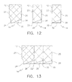
- FIG. 12 is a side view in section of a rotary seal built in segmented fashion.
- FIG. 13 is a side view in section of a rotary seal built in segmented fashion and installed in a seal housing.
- FIG. 14 is side view in section of an alternative fluid pocket design in the sealing surface.
- FIG. 15 is a detailed view of the contact surface of the alternative fluid pocket design of the rotary seal as it engages the shaft surface.
- a rotary seal for dynamically sealing against a surface of a shaft generally identified by reference numeral 10 will now be described with reference to FIG. 1 through 14 .
- rotary seal 10 includes a seal body 12 having a sealing surface 14 and an outer surface 16 .
- the seal body 12 is described as being formed of an elastomer. However, any suitable material or combination of materials known by those skilled in the art may also be used.
- sealing surface 14 is adapted to engage the surface 18 of a shaft 20 , such that shaft 20 is permitted to rotate relative to seal body 12 .
- Outer surface 16 is adapted to engage a housing 22 . While the description below describes the shaft as the body that rotates, it will be understood that the shaft rotation is relative to the seal and housing. Thus, the shaft could be stationary with the seal and housing in rotation. It will also be understood that the seal could be mounted in the shaft, rather than the housing as described herein.
- the term “shaft” is intended to describe any substantially cylindrical body that may be sealed by seal 10 in the manner described herein.
- sealing surface 14 has a sealing lip 24 positioned toward a first side edge 23 of sealing surface 14 .
- Support ribs 26 extend from sealing lip 24 toward a second side edge 25 of sealing surface 14 .
- Support ribs 26 are designed to engage surface 18 of shaft 20 .
- support ribs 26 form discrete fluid openings 30 for receiving a second fluid, such as a lubricant.
- sealing lip 24 is designed to be equal to or extend below support ribs 26 such that it forms a seal when rotary seal 10 is installed on the surface of the shaft (as shown in FIG. 11 ). Sealing lip 24 seals against a first fluid, such as an abrasive hydrocarbon flow in an oilfield application.
- sealing lip 24 there may be secondary, or additional sealing lips 32 spaced between sealing lip 24 and second side edge 25 of sealing surface 14 .
- sealing lip 24 , secondary sealing lips 32 and support ribs 26 form discrete fluid pockets 28 . While three sealing lips 24 and 32 are shown in FIG. 7 , it will be understood that even more secondary sealing lips 32 may be included to form additional rows of pockets 28 . The number of rows may be increased in order to accommodate increased magnitudes of pressure (described below), with the limitation being the practical length of the seal.
- sealing lips 32 of these shapes may have increased or decreased contact pressure with surface 18 of shaft 20 to form fluid pockets 28 as application and design requires.
- sealing surface 14 is designed to cause lubricant to migrate from second side edge 25 toward first side edge 23 .
- Lubricant gains access to first side edge 23 by second side edge 25 by entering openings 30 between support ribs 26 .
- Shaft 20 rotating relative to sealing surface 14 causes support ribs 26 to apply a migration force on the second fluid. By doing so, lubricant lubricates surface 18 of shaft 20 and support ribs 26 and sealing lip 24 .
- FIGS. 6 and 8 which have discrete fluid pockets 28 , vibrations due to imperfections in the dynamic motion of shaft 20 cause fluctuations in pressure in fluid pockets 28 . These imperfections may be caused by off-axis rotation, the shaft not having a slightly elliptical cross-section, or from vibrations due to the drive that rotates shaft 20 . Similar considerations also cause these fluctuations if housing 22 rotates and shaft 20 is stationary.
- These pockets 28 when filled with clean lubricant, are essentially incompressible fluid reservoirs that “feed” the hydrodynamic fluid film formed between the sealing tips 24 , 32 and support ribs 26 (as well as additional sealing lips 32 when there are two or more sealing lips as shown in FIG. 8 ), and shaft 20 .
- each fluid pocket 28 may be considered a “small pump” that ensures a hydrodynamic fluid film of clean lubricant fluid from second side edge 25 is maintained between primary seal lip 24 and shaft 20 .
- FIGS. 9 and 10 show alternate shapes of both primary seal lip 24 and second seal lip 32 for the embodiment depicted in FIG. 5 , which may allow seal 10 to achieve better results for particular applications.
- FIG. 9 shows a variation of the embodiment in FIG. 5 with second lip 32 formed in the shape of an “O”-Ring. This example demonstrates the variation that is possible with the seal configuration.
- “O”-Ring seals do not perform well in rotary applications due to the distortion of its shape under pressure and the contact pressure resulting against the rotating surface 18 of rotating shaft 20 .
- FIG. 10 is another variation of FIG. 5 with second lip 32 formed in the shape of a “B”-Style seal lip. It is known that this shape of seal lip results in much higher contact pressures between the seal lip 32 and the rotating surface 18 of shaft 20 and may be desirable in some applications. It will be understood that other shapes or combinations of shapes may also be used for a wide range of applications.
- FIGS. 4 , 6 and 8 may be described in terms of circumferential components (or seal lips) and axial components (or support ribs), where the axial components need not be perpendicular to the circumferential components, and may not have parallel faces.
- One example may be a footprint where fluid pockets 28 and/or openings 27 (depending on the embodiment) are formed as round depressions in sealing surface 14 .
- Another example is where secondary sealing lips 32 are not straight, such that pockets 28 are offset from other adjacent pockets 28 .
- FIG. 14 is another means to achieve fluid pockets adjacent to sealing lip 24 through the use of a “dimple” design, similar to the surface of a golf ball. As can be seen in this embodiment, it is also not necessary to include lip 24 , however, lip 24 is desirable in most circumstances. Other designs using these principles will be apparent to those skilled in the art.
- pockets 28 may be formed between primary seal lip 24 of one seal body 12 , and openings 30 of another seal body 12 that meet appropriately when subjected to pressure.
- Some considerations that are incorporated in this design include: a compressive mounting of the seal onto the shaft, a tapered lip style to create the barrier between the abrasive fluid and the clean lubricating fluid, a displaced seal lip to prevent “nibbling” from the gland, and ensuring a hydrodynamic fluid film between the elastomer seal and rotating shaft for varied pressure conditions.
- seal 10 In providing a hydrodynamic film, the friction between the seal and the surface of the shaft may be reduced.
- seal 10 consists of tapered seal lip 24 that is set back from first side edge 23 of sealing surface 14 , (seal lip 24 is set back is to prevent “nibbling” from the gland to shaft clearance).
- Support ribs 26 remain open to the lubricating fluid supplied opposite the fluid to be sealed. Each rib 26 is in contact with shaft 20 , (shown in FIG. 11 ), and provides a constant “wiping” of fluid off shaft 20 as shaft 20 rotates.
- Advantages to this design are control of the hydrodynamic film through differences in shaft interference of tapered seal lip 24 and ribs 26 , as well as the number of ribs 26 provided in each seal 10 .
- the performance of this design may be limited by the magnitude of the contained pressure due to the tendency of an elastomer to deform under pressure.
- the rib design offers resistance to this deformation.
- fluid pockets 28 such as shown in FIGS. 6 and 8 , also provide structural support to resist deformation when filled with incompressible lubricant.
- seal 10 One of the key design features of seal 10 is the provision of a means to trap clean lubricating oil in small pockets 28 behind primary seal lip 24 .
- the oil trapped in pockets 28 is subjected to same pressure as the elastomer. Because the oil is substantially incompressible, it maintains its presence and provides an amount of lubricant directly to primary seal lip 24 . This helps prevent starving the elastomer of a hydrodynamic film as pressures increase.
- Ribs 26 also tend to support the structure of pockets 28 and provide inlet means 27 for the clean lubricants. Given the benefits of this feature, the performance of seal 10 in different pressure situations will now be discussed with reference to the embodiment shown in FIGS. 5 and 6 . Similar considerations may be applied to the other embodiments discussed.
- the pressure of the second fluid is greater than the pressure of the abrasive contaminated fluid.
- second seal lip 32 and ribs 26 that form pockets 28 on the high-pressure side of primary seal lip 24 serve many purposes:
- the clean hydraulic lubricant fluid pressure is equal to the pressure of the abrasive contaminated fluid.
- This may be the ideal condition for seal 10 .
- ribs 26 provide lubricant openings 27 for the hydrodynamic film.
- This in combination with the dynamic imperfections of the shaft rotation, acting on fluid pockets 28 , may provide the appropriate amount of lubricant to primary seal lip 24 for higher speeds. This is beneficial because reducing the applied pressure on an elastomer seal allows the seal to be used more successfully at higher speeds.
- FIG. 1 shows a seal body 12 with an opening and 20 ribs 26 .
- the number of ribs may be changed in order to vary the size of sealed pockets 28 , and the number of contact points on shaft 20 .
- seal 10 In the reverse pressure condition, the clean hydraulic lubricant fluid pressure is less than the pressure of the abrasive contaminated fluid. This condition is the most difficult to accommodate successfully. It should be recognized, however that seal 10 does not have the same inherent problems associated with other designs. With primary seal lip and support ribs, FIG. 2 , reverse pressure conditions do not deform seal body 12 to produce pressure pivots or high and low-pressure contact areas in seal surface 14 due to the supporting rib structure. In the sealed pocket design, FIGS. 5 and 7 , the fluid filled pressure pockets 28 further resist reverse pressure conditions. Compression of seal body 12 in the reverse pressure condition results in compression of the clean lubricating oil sealed in pockets 28 behind primary seal lip 24 . As in the high-pressure lubricant condition, sealed pockets 28 reduce the area of high-pressure contact between the elastomer and rotating shaft 20 by sealed pockets 28 of incompressible lubricant.
Landscapes
- Engineering & Computer Science (AREA)
- General Engineering & Computer Science (AREA)
- Mechanical Engineering (AREA)
- Physics & Mathematics (AREA)
- Fluid Mechanics (AREA)
- Sealing With Elastic Sealing Lips (AREA)
Priority Applications (1)
| Application Number | Priority Date | Filing Date | Title |
|---|---|---|---|
| US11/697,001 US9004494B2 (en) | 2006-04-05 | 2007-04-05 | Rotary seal for dynamically sealing against a surface of a shaft |
Applications Claiming Priority (2)
| Application Number | Priority Date | Filing Date | Title |
|---|---|---|---|
| US78931806P | 2006-04-05 | 2006-04-05 | |
| US11/697,001 US9004494B2 (en) | 2006-04-05 | 2007-04-05 | Rotary seal for dynamically sealing against a surface of a shaft |
Publications (2)
| Publication Number | Publication Date |
|---|---|
| US20070246894A1 US20070246894A1 (en) | 2007-10-25 |
| US9004494B2 true US9004494B2 (en) | 2015-04-14 |
Family
ID=38621131
Family Applications (1)
| Application Number | Title | Priority Date | Filing Date |
|---|---|---|---|
| US11/697,001 Expired - Fee Related US9004494B2 (en) | 2006-04-05 | 2007-04-05 | Rotary seal for dynamically sealing against a surface of a shaft |
Country Status (2)
| Country | Link |
|---|---|
| US (1) | US9004494B2 (fr) |
| CA (1) | CA2584357C (fr) |
Cited By (1)
| Publication number | Priority date | Publication date | Assignee | Title |
|---|---|---|---|---|
| US20150210314A1 (en) * | 2012-08-09 | 2015-07-30 | Tatsuro Hosen | Dust cover for ball joint |
Families Citing this family (3)
| Publication number | Priority date | Publication date | Assignee | Title |
|---|---|---|---|---|
| US9109703B2 (en) * | 2010-02-11 | 2015-08-18 | Kalsi Engineering, Inc. | Hydrodynamic backup ring |
| US20140264126A1 (en) * | 2013-03-13 | 2014-09-18 | Gssc, Inc. | Reduced Wear Valve |
| EP3339654B1 (fr) * | 2016-12-20 | 2021-03-03 | Grundfos Holding A/S | Pompe centrifuge |
Citations (11)
| Publication number | Priority date | Publication date | Assignee | Title |
|---|---|---|---|---|
| US3729204A (en) * | 1969-08-16 | 1973-04-24 | Kupfer Asbest Co | Sealing sleeve, especially for radial shaft sealing rings |
| US4118856A (en) * | 1974-12-02 | 1978-10-10 | Garlock Inc | Bi-directional hydrodynamic shaft seal method |
| US4399998A (en) * | 1981-12-28 | 1983-08-23 | The Timken Company | Self-venting seal lip |
| US4568092A (en) * | 1983-05-03 | 1986-02-04 | Firma Carl Freudenberg | Lip seal |
| US5667225A (en) * | 1995-02-17 | 1997-09-16 | Renk Aktiengesellschaft | Self-draining shaft seal with wedge-shaped trough |
| US5873576A (en) * | 1995-06-27 | 1999-02-23 | Kalsi Engineering, Inc. | Skew and twist resistant hydrodynamic rotary shaft seal |
| WO2000065257A1 (fr) | 1999-04-26 | 2000-11-02 | Kalsi Engineering, Inc. | Dispositif d'etancheite hydrodynamique a resistance amelioree a l'extrusion, a l'abrasion et a la torsion |
| US6203024B1 (en) * | 1997-03-05 | 2001-03-20 | Contitech Formteile Gmbh | Bellows |
| US20040004326A1 (en) * | 2002-07-02 | 2004-01-08 | Liming Lou | Sealing device and sliding member |
| US6863661B2 (en) * | 2000-05-17 | 2005-03-08 | Scimed Life Systems, Inc. | Fluid seal for endoscope |
| US7052020B2 (en) | 1999-05-19 | 2006-05-30 | Kalsi Engineering, Inc. | Hydrodynamic rotary seal |
-
2007
- 2007-04-05 CA CA2584357A patent/CA2584357C/fr active Active
- 2007-04-05 US US11/697,001 patent/US9004494B2/en not_active Expired - Fee Related
Patent Citations (11)
| Publication number | Priority date | Publication date | Assignee | Title |
|---|---|---|---|---|
| US3729204A (en) * | 1969-08-16 | 1973-04-24 | Kupfer Asbest Co | Sealing sleeve, especially for radial shaft sealing rings |
| US4118856A (en) * | 1974-12-02 | 1978-10-10 | Garlock Inc | Bi-directional hydrodynamic shaft seal method |
| US4399998A (en) * | 1981-12-28 | 1983-08-23 | The Timken Company | Self-venting seal lip |
| US4568092A (en) * | 1983-05-03 | 1986-02-04 | Firma Carl Freudenberg | Lip seal |
| US5667225A (en) * | 1995-02-17 | 1997-09-16 | Renk Aktiengesellschaft | Self-draining shaft seal with wedge-shaped trough |
| US5873576A (en) * | 1995-06-27 | 1999-02-23 | Kalsi Engineering, Inc. | Skew and twist resistant hydrodynamic rotary shaft seal |
| US6203024B1 (en) * | 1997-03-05 | 2001-03-20 | Contitech Formteile Gmbh | Bellows |
| WO2000065257A1 (fr) | 1999-04-26 | 2000-11-02 | Kalsi Engineering, Inc. | Dispositif d'etancheite hydrodynamique a resistance amelioree a l'extrusion, a l'abrasion et a la torsion |
| US7052020B2 (en) | 1999-05-19 | 2006-05-30 | Kalsi Engineering, Inc. | Hydrodynamic rotary seal |
| US6863661B2 (en) * | 2000-05-17 | 2005-03-08 | Scimed Life Systems, Inc. | Fluid seal for endoscope |
| US20040004326A1 (en) * | 2002-07-02 | 2004-01-08 | Liming Lou | Sealing device and sliding member |
Cited By (2)
| Publication number | Priority date | Publication date | Assignee | Title |
|---|---|---|---|---|
| US20150210314A1 (en) * | 2012-08-09 | 2015-07-30 | Tatsuro Hosen | Dust cover for ball joint |
| US9254867B2 (en) * | 2012-08-09 | 2016-02-09 | Nok Corporation | Dust cover for ball joint |
Also Published As
| Publication number | Publication date |
|---|---|
| CA2584357A1 (fr) | 2007-10-05 |
| US20070246894A1 (en) | 2007-10-25 |
| CA2584357C (fr) | 2015-12-29 |
Similar Documents
| Publication | Publication Date | Title |
|---|---|---|
| US6036192A (en) | Skew and twist resistant hydrodynamic rotary shaft seal | |
| US3973781A (en) | Self-lubricating seal | |
| US6109618A (en) | Rotary seal with enhanced lubrication and contaminant flushing | |
| JP5604530B2 (ja) | 回転シール装置 | |
| US4610319A (en) | Hydrodynamic lubricant seal for drill bits | |
| EP2754928B1 (fr) | Dispositif d'étanchéité d'arbre | |
| KR102180853B1 (ko) | 레이디얼 샤프트 시일 | |
| US9784372B2 (en) | Sealing device | |
| US8919782B2 (en) | Dynamic lay down lip seal with bidirectional pumping feature | |
| EP2816262B1 (fr) | Dispositif d'étanchéité d'arbre | |
| US3534969A (en) | Seal | |
| EP2816261B1 (fr) | Dispositif d'étanchéité d'arbre | |
| CN112771279B (zh) | 具有密封装置的滑动轴承和具有滑动轴承的水泵 | |
| US20120038113A1 (en) | Hydrodynamic backup ring | |
| US20130154192A1 (en) | Sealing assembly | |
| CA2584357C (fr) | Joint pour mouvement rotatif permettant d'etancheifier dynamiquement la surface d'un arbre | |
| US10907689B2 (en) | Heavy duty wheel seal with dry running resistance | |
| US8651496B2 (en) | Seal | |
| US7661883B2 (en) | Sealing element for a rotatable part with a tractrix form | |
| US20210396241A1 (en) | Rolling bearing having a sealing assembly and water pump having same | |
| KR102346413B1 (ko) | 슬라이딩 부품 | |
| CN110425284B (zh) | 一种密封件 | |
| JP3922729B2 (ja) | ラジアルニードル軸受 | |
| KR20090040956A (ko) | 가스터빈용 베어링 시일 | |
| KR20230145489A (ko) | 밀봉 구조 및 밀봉 방법 |
Legal Events
| Date | Code | Title | Description |
|---|---|---|---|
| FEPP | Fee payment procedure |
Free format text: PAYOR NUMBER ASSIGNED (ORIGINAL EVENT CODE: ASPN); ENTITY STATUS OF PATENT OWNER: SMALL ENTITY |
|
| STCF | Information on status: patent grant |
Free format text: PATENTED CASE |
|
| MAFP | Maintenance fee payment |
Free format text: PAYMENT OF MAINTENANCE FEE, 4TH YR, SMALL ENTITY (ORIGINAL EVENT CODE: M2551); ENTITY STATUS OF PATENT OWNER: SMALL ENTITY Year of fee payment: 4 |
|
| FEPP | Fee payment procedure |
Free format text: MAINTENANCE FEE REMINDER MAILED (ORIGINAL EVENT CODE: REM.); ENTITY STATUS OF PATENT OWNER: SMALL ENTITY |
|
| LAPS | Lapse for failure to pay maintenance fees |
Free format text: PATENT EXPIRED FOR FAILURE TO PAY MAINTENANCE FEES (ORIGINAL EVENT CODE: EXP.); ENTITY STATUS OF PATENT OWNER: SMALL ENTITY |
|
| STCH | Information on status: patent discontinuation |
Free format text: PATENT EXPIRED DUE TO NONPAYMENT OF MAINTENANCE FEES UNDER 37 CFR 1.362 |
|
| FP | Lapsed due to failure to pay maintenance fee |
Effective date: 20230414 |