US8994420B2 - Higher-order phase noise modulator to reduce spurs and quantization noise - Google Patents
Higher-order phase noise modulator to reduce spurs and quantization noise Download PDFInfo
- Publication number
- US8994420B2 US8994420B2 US13/469,936 US201213469936A US8994420B2 US 8994420 B2 US8994420 B2 US 8994420B2 US 201213469936 A US201213469936 A US 201213469936A US 8994420 B2 US8994420 B2 US 8994420B2
- Authority
- US
- United States
- Prior art keywords
- phase
- control signal
- signal
- sigma
- modulator
- Prior art date
- Legal status (The legal status is an assumption and is not a legal conclusion. Google has not performed a legal analysis and makes no representation as to the accuracy of the status listed.)
- Active
Links
Images


Classifications
-
- H—ELECTRICITY
- H03—ELECTRONIC CIRCUITRY
- H03L—AUTOMATIC CONTROL, STARTING, SYNCHRONISATION OR STABILISATION OF GENERATORS OF ELECTRONIC OSCILLATIONS OR PULSES
- H03L7/00—Automatic control of frequency or phase; Synchronisation
- H03L7/06—Automatic control of frequency or phase; Synchronisation using a reference signal applied to a frequency- or phase-locked loop
- H03L7/08—Details of the phase-locked loop
- H03L7/081—Details of the phase-locked loop provided with an additional controlled phase shifter
-
- H—ELECTRICITY
- H03—ELECTRONIC CIRCUITRY
- H03L—AUTOMATIC CONTROL, STARTING, SYNCHRONISATION OR STABILISATION OF GENERATORS OF ELECTRONIC OSCILLATIONS OR PULSES
- H03L7/00—Automatic control of frequency or phase; Synchronisation
- H03L7/06—Automatic control of frequency or phase; Synchronisation using a reference signal applied to a frequency- or phase-locked loop
- H03L7/08—Details of the phase-locked loop
-
- H—ELECTRICITY
- H03—ELECTRONIC CIRCUITRY
- H03L—AUTOMATIC CONTROL, STARTING, SYNCHRONISATION OR STABILISATION OF GENERATORS OF ELECTRONIC OSCILLATIONS OR PULSES
- H03L7/00—Automatic control of frequency or phase; Synchronisation
- H03L7/06—Automatic control of frequency or phase; Synchronisation using a reference signal applied to a frequency- or phase-locked loop
- H03L7/16—Indirect frequency synthesis, i.e. generating a desired one of a number of predetermined frequencies using a frequency- or phase-locked loop
- H03L7/18—Indirect frequency synthesis, i.e. generating a desired one of a number of predetermined frequencies using a frequency- or phase-locked loop using a frequency divider or counter in the loop
- H03L7/197—Indirect frequency synthesis, i.e. generating a desired one of a number of predetermined frequencies using a frequency- or phase-locked loop using a frequency divider or counter in the loop a time difference being used for locking the loop, the counter counting between numbers which are variable in time or the frequency divider dividing by a factor variable in time, e.g. for obtaining fractional frequency division
- H03L7/1974—Indirect frequency synthesis, i.e. generating a desired one of a number of predetermined frequencies using a frequency- or phase-locked loop using a frequency divider or counter in the loop a time difference being used for locking the loop, the counter counting between numbers which are variable in time or the frequency divider dividing by a factor variable in time, e.g. for obtaining fractional frequency division for fractional frequency division
- H03L7/1976—Indirect frequency synthesis, i.e. generating a desired one of a number of predetermined frequencies using a frequency- or phase-locked loop using a frequency divider or counter in the loop a time difference being used for locking the loop, the counter counting between numbers which are variable in time or the frequency divider dividing by a factor variable in time, e.g. for obtaining fractional frequency division for fractional frequency division using a phase accumulator for controlling the counter or frequency divider
-
- H—ELECTRICITY
- H03—ELECTRONIC CIRCUITRY
- H03M—CODING; DECODING; CODE CONVERSION IN GENERAL
- H03M7/00—Conversion of a code where information is represented by a given sequence or number of digits to a code where the same, similar or subset of information is represented by a different sequence or number of digits
- H03M7/30—Compression; Expansion; Suppression of unnecessary data, e.g. redundancy reduction
- H03M7/3002—Conversion to or from differential modulation
- H03M7/3004—Digital delta-sigma modulation
- H03M7/3015—Structural details of digital delta-sigma modulators
- H03M7/302—Structural details of digital delta-sigma modulators characterised by the number of quantisers and their type and resolution
- H03M7/3022—Structural details of digital delta-sigma modulators characterised by the number of quantisers and their type and resolution having multiple quantisers arranged in cascaded loops, each of the second and further loops processing the quantisation error of the loop preceding it, i.e. multiple stage noise shaping [MASH] type
-
- H—ELECTRICITY
- H03—ELECTRONIC CIRCUITRY
- H03M—CODING; DECODING; CODE CONVERSION IN GENERAL
- H03M7/00—Conversion of a code where information is represented by a given sequence or number of digits to a code where the same, similar or subset of information is represented by a different sequence or number of digits
- H03M7/30—Compression; Expansion; Suppression of unnecessary data, e.g. redundancy reduction
- H03M7/3002—Conversion to or from differential modulation
- H03M7/3004—Digital delta-sigma modulation
- H03M7/3015—Structural details of digital delta-sigma modulators
- H03M7/302—Structural details of digital delta-sigma modulators characterised by the number of quantisers and their type and resolution
- H03M7/3024—Structural details of digital delta-sigma modulators characterised by the number of quantisers and their type and resolution having one quantiser only
- H03M7/3026—Structural details of digital delta-sigma modulators characterised by the number of quantisers and their type and resolution having one quantiser only the quantiser being a multiple bit one
-
- H—ELECTRICITY
- H03—ELECTRONIC CIRCUITRY
- H03M—CODING; DECODING; CODE CONVERSION IN GENERAL
- H03M7/00—Conversion of a code where information is represented by a given sequence or number of digits to a code where the same, similar or subset of information is represented by a different sequence or number of digits
- H03M7/30—Compression; Expansion; Suppression of unnecessary data, e.g. redundancy reduction
- H03M7/3002—Conversion to or from differential modulation
- H03M7/3004—Digital delta-sigma modulation
- H03M7/3015—Structural details of digital delta-sigma modulators
- H03M7/3031—Structural details of digital delta-sigma modulators characterised by the order of the loop filter, e.g. having a first order loop filter in the feedforward path
- H03M7/3033—Structural details of digital delta-sigma modulators characterised by the order of the loop filter, e.g. having a first order loop filter in the feedforward path the modulator having a higher order loop filter in the feedforward path, e.g. with distributed feedforward inputs
- H03M7/3037—Structural details of digital delta-sigma modulators characterised by the order of the loop filter, e.g. having a first order loop filter in the feedforward path the modulator having a higher order loop filter in the feedforward path, e.g. with distributed feedforward inputs with weighted feedforward summation, i.e. with feedforward paths from more than one filter stage to the quantiser input
-
- H—ELECTRICITY
- H03—ELECTRONIC CIRCUITRY
- H03M—CODING; DECODING; CODE CONVERSION IN GENERAL
- H03M7/00—Conversion of a code where information is represented by a given sequence or number of digits to a code where the same, similar or subset of information is represented by a different sequence or number of digits
- H03M7/30—Compression; Expansion; Suppression of unnecessary data, e.g. redundancy reduction
- H03M7/3002—Conversion to or from differential modulation
- H03M7/3004—Digital delta-sigma modulation
- H03M7/3015—Structural details of digital delta-sigma modulators
- H03M7/3031—Structural details of digital delta-sigma modulators characterised by the order of the loop filter, e.g. having a first order loop filter in the feedforward path
- H03M7/3033—Structural details of digital delta-sigma modulators characterised by the order of the loop filter, e.g. having a first order loop filter in the feedforward path the modulator having a higher order loop filter in the feedforward path, e.g. with distributed feedforward inputs
- H03M7/304—Structural details of digital delta-sigma modulators characterised by the order of the loop filter, e.g. having a first order loop filter in the feedforward path the modulator having a higher order loop filter in the feedforward path, e.g. with distributed feedforward inputs with distributed feedback, i.e. with feedback paths from the quantiser output to more than one filter stage
-
- H—ELECTRICITY
- H03—ELECTRONIC CIRCUITRY
- H03M—CODING; DECODING; CODE CONVERSION IN GENERAL
- H03M7/00—Conversion of a code where information is represented by a given sequence or number of digits to a code where the same, similar or subset of information is represented by a different sequence or number of digits
- H03M7/30—Compression; Expansion; Suppression of unnecessary data, e.g. redundancy reduction
- H03M7/3002—Conversion to or from differential modulation
- H03M7/3004—Digital delta-sigma modulation
- H03M7/3015—Structural details of digital delta-sigma modulators
- H03M7/3031—Structural details of digital delta-sigma modulators characterised by the order of the loop filter, e.g. having a first order loop filter in the feedforward path
- H03M7/3042—Structural details of digital delta-sigma modulators characterised by the order of the loop filter, e.g. having a first order loop filter in the feedforward path the modulator being of the error feedback type, i.e. having loop filter stages in the feedback path only
Definitions
- This invention relates to generating clock signals for electronic devices.
- Clock synthesizers generate clock signals utilized by a wide variety of electronic products.
- a typical clock synthesizer utilizes a phase-locked loop (PLL) supplied with a reference signal from a source such as a crystal oscillator.
- the output frequency of the signal supplied by the synthesizer can be determined by a divider value of the feedback divider in the PLL.
- a reference frequency supplied to the PLL is multiplied based on the divider value to generate the synthesized clock frequency.
- feedback divider 118 of PLL 100 may be an integer divider, which divides the reference frequency clock signal by an integer value, N.
- FIG. 2A illustrates a PLL 100 with a fractional-N feedback divider 119 .
- DIVIDE RATIO is a digital frequency ratio translated from a code, e.g., a code provided by non-volatile memory (NVM).
- NVM non-volatile memory
- Sigma-delta modulator 121 supplies a divide sequence to fractional-N feedback divider 119 .
- Fractional-N divider 119 receives a divide value sequence corresponding to the target divider ratio.
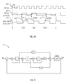
- FIG. 2B illustrates a timing diagram of a divide by 2.25.
- the input clock (REFCLK) is shown as waveform 201 as having a period of one unit interval (UI).
- the output of the fractional-N divider, DIVCLK is shown in waveform 203 .
- the divide ratio of 2.25 is achieved by a sequence of divide by 2 for three periods and a divide by 3 for one period, assuming a first order sigma-delta modulator is used to control the fractional-N divider.
- Waveform 205 illustrates the ideal waveform for a divide ratio of 2.25.
- the quantization noise of the modulator, at the output of the divider 118 is shown as the difference at 207 , 209 , and 211 , between the actual output of the fractional-N divider shown in waveform 203 and the ideal output for a divide by 2.25 shown in waveform 205 .
- fractional-N divider 119 supplies the divided signal to phase detector 112 with noise associated with the nature of the fractional-N divider.
- the fractional-N noise may be filtered out by the PLL loop.
- phase error correction may be utilized to address the jitter introduced by the divider by introducing an offset into the PLL corresponding to the jitter generated by the fractional-N divider.
- clock synthesizers may require a complex loop filter and complex voltage-controlled oscillator control that increase the cost in design effort and chip area, resulting in more expensive products that may be too expensive in cost or real estate for significant portions of the clock synthesizer market. Accordingly, low-cost, low-noise, flexible clock synthesizer techniques are desired.
- an apparatus in at least one embodiment of the invention, includes a frequency modulator configured to generate a divide control signal and a digital quantization error signal in response to a divide ratio.
- the apparatus includes a phase modulator configured to generate a phase error signal based on the digital quantization error signal.
- the phase modulator is an n-order sigma-delta modulator module, n being an integer greater than one.
- the apparatus may include an interpolative divider configured to generate a feedback signal in a phase-locked loop (PLL) based on an output signal of the PLL, the divide control signal, and the phase error signal.
- the interpolative divider may include the frequency modulator and the phase modulator.
- the phase modulator may have a unity gain signal transfer function.
- a method includes receiving a divide ratio in a sigma-delta modulator and generating an integer portion and a digital quantization error corresponding to the divide ratio.
- the method includes supplying the integer portion as a divide control signal to an interpolative divider in a feedback loop of a phase-locked loop (PLL).
- the method includes receiving the digital quantization error in a multi-order sigma-delta modulator and generating a phase error signal corresponding to the digital quantization error.
- the method includes supplying the phase error signal to the interpolative divider.
- the multi-order sigma-delta modulator may have a unity gain signal transfer function.
- FIG. 1 illustrates a functional block diagram of a phase-locked loop including an integer frequency divider.
- FIG. 2A illustrates a functional block diagram of a phase-locked loop including a fractional-N frequency divider.
- FIG. 2B illustrates timing waveforms for the phase-locked loop of FIG. 2A .
- FIG. 3 illustrates a functional block diagram of a third-order sigma-delta modulator of the PLL of FIG. 2A .
- FIG. 4 illustrates a functional block diagram of a PLL including an interpolative divider.
- FIG. 5 illustrates a functional block diagram of a modulator module of the interpolative divider of FIG. 4 .
- FIG. 6 illustrates a functional block diagram of a PLL including an interpolative divider having a frequency modulator and a phase modulator consistent with at least one embodiment of the invention.
- FIG. 7 illustrates a functional block diagram of a phase modulator module having a multi-stage noise shaping (MASH) 111 configuration consistent with at least one embodiment of the invention.
- MASH multi-stage noise shaping
- FIG. 8 illustrates a functional block diagram of a phase modulator module having a MASH 21 configuration consistent with at least one embodiment of the invention.
- FIG. 9 illustrates a functional block diagram of a phase modulator module having a third-order feedforward configuration consistent with at least one embodiment of the invention.
- FIG. 10 illustrates a functional block diagram of a phase modulator module having a third-order feedback configuration consistent with at least one embodiment of the invention.
- FIG. 11 illustrates a functional block diagram of a phase modulator module having a second-order feedback configuration consistent with at least one embodiment of the invention.
- PLL 100 includes a phase/frequency detector (PFD) 112 , a loop filter 114 , and a voltage controlled oscillator (VCO) 116 .
- Loop filter 114 may be implemented as a digital loop filter to avoid the necessity of off-chip capacitors.
- VCO 112 may be implemented as a ring oscillator or as an LC oscillator. Other oscillator structures may also be utilized.
- PFD 112 receives a reference clock signal, which can come from a fixed source such as a crystal oscillator or micro electro mechanical structure (MEMS) oscillator.
- a non-volatile memory (not shown) may supply a divide ratio to divider 118 , which is in the feedback path of PLL 100 .
- Divider 118 includes sigma-delta modulator 121 , which is a typical first-order sigma-delta modulator.
- fractional-N divider 119 introduces a digital quantization error that causes phase noise (i.e., jitter) in the feedback clock signal DIVCLK.
- An exemplary technique for reducing or cancelling the phase noise introduced into the feedback signal of phase-locked loop (PLL) 100 by fractional-N divider 119 includes use of a higher-order sigma-delta modulator to generate the divider control signal DIVCODE.
- FIG. 3 illustrates exemplary third-order sigma-delta modulator 121 that can be used to generate the DIVCODE for fractional-N divider 119 of FIG. 2A .
- the resulting PLL requires a high update rate, which increases the cost of the reference clock.
- the resulting PLL requires a highly linear phase detector and charge pump to prevent quantization noise from being mixed down to DC.
- another technique for reducing jitter in a fractional-N divider includes adjusting the phase of the frequency-divided signal according to a phase error control signal, PICODE, generated by interpolative divider 120 .
- Interpolative divider 120 includes phase interpolator 122 that interpolates the phase of the output of fractional-N divider 119 thereby introducing a phase adjustment prior to phase detector 112 of PLL 100 .
- Modulator module 160 generates the DIVCODE for fractional-N divider 119 .
- modulator module 160 generates PICODE and supplies it to phase interpolator 122 .
- Phase interpolator 122 interpolates between the frequency-divided signal and one or more delayed versions of the frequency-divided signal (one or more equally spaced phases of the frequency-divided signal) based on the PICODE, which corresponds to the phase error, using techniques that are well known in the art.
- Interpolative divider 120 provides the output of phase interpolator 122 to phase detector 112 .
- An exemplary modulator module 160 includes a first-order sigma-delta modulator that may be implemented in digital circuitry (e.g., using digital delay elements, adders, comparators, etc.).
- sigma-delta modulator 161 generates both the PICODE and the DIVCODE.
- the DIVCODE is a truncated version (i.e., integer portion) of the integrator output signal and the PICODE (which corresponds to the digital quantization error) is the truncated portion (i.e., fractional portion) of the integrator output signal.
- DIVCODE is a one-bit code having a range of integer values 0 ⁇ DIVCODE ⁇ 1 and the PICODE is an eight-bit code, having a range of values of 0 ⁇ PICODE ⁇ (2 8 ⁇ 1).
- the phase error associated with first-order frequency modulator 122 is uniformly distributed.
- Phase interpolator 122 uses the PICODE to reduce or eliminate the phase error before phase detector 112 , thereby reducing the linearity requirements on phase detector 112 .
- quantization error from the phase interpolator digital-to-analog conversion introduces spurs into the feedback signal.
- Linearity and gain error of phase interpolator 122 introduces spurs and high jitter.
- a technique for reducing spurs and quantization noise includes using frequency modulator 161 to generate the DIVCODE 1 , which corresponds to an integer portion of the divide ratio.
- frequency modulator 161 generates a high-resolution (e.g., greater than eight bits) phase error signal POUT that corresponds to the quantization error associated with the DIVCODE.
- Phase modulator 163 includes a higher-order sigma-delta modulator that generates a lower-resolution PICODE based on that quantization error signal.
- phase modulator 163 receives POUT having a number of bits that is much greater than the number of bits in PICODE (e.g., eight bits).
- frequency modulator 161 includes a first-order sigma-delta modulator and phase modulator 163 includes a higher-order (i.e., at least second order) sigma-delta modulator.
- frequency modulator 161 and phase modulator 163 can have higher orders.
- Typical higher-order sigma delta modulators attenuate high-frequency energy of the signal (i.e., the signal transfer function (STF) is a low-pass filter) and shape the noise (i.e., the noise transfer function (NTF) pushes noise energy into higher frequencies).
- STF signal transfer function
- NTF noise transfer function
- Typical applications take advantage of those characteristics of higher-order sigma-delta modulators.
- By low-pass filtering the signal high-frequency signal information is lost and results in increased jitter seen by the phase detector 112 .
- the information represented by the high-frequency energy of the signal is not needed. However, in high-bandwidth applications, the high-frequency signal information is needed to generate a phase error signal indicative of the phase noise.
- phase modulator 163 has a high-bandwidth signal-transfer function.
- Phase modulator 163 has a signal-transfer function that does not substantially attenuate the signal in a frequency band-of-interest.
- phase modulator 163 has a unity gain signal-transfer function (i.e.,
- 1). Any zeros in the signal transfer function (STF) of a unity gain signal transfer function reside at the origin.
- phase modulator 163 Any noise energy that has been pushed into high frequencies by phase modulator 163 is filtered by loop filter 114 .
- phase modulators having other signal transfer functions may be used in applications that can tolerate any associated increase in quantization error.
- phase modulator 163 has been described in a particular phase-locked loop system, one of skill in the art will appreciate that the teachings herein can be utilized with other closed-loop systems or in open-loop systems that include a high quality factor (i.e., high Q) filter or can tolerate high-frequency noise.
- a high quality factor i.e., high Q
- frequency modulator 161 is implemented by first-order sigma-delta modulator 160 of FIG. 5 .
- a dither signal is introduced in frequency modulator 161 .
- a dither signal may be introduced in phase modulator 163 .
- Frequency modulator 161 provides the phase error signal, which is the output of quantizer Q 2 of frequency modulator 160 , to phase modulator 163 as POUT, and provides the output of quantizer Q 1 of frequency modulator 160 , to phase modulator 163 as DIVCODE 1 .
- frequency modulator 161 has a different first-order, or a higher-order, sigma-delta configuration.
- increasing the order of sigma-delta modulator in frequency modulator 161 may not improve the phase noise if the order of sigma-delta modulator in the phase modulator 163 is not also increased.
- phase modulator 163 includes a sigma-delta modulator having an order greater than one and having a wideband signal transfer function (e.g., a unity gain signal transfer function, i.e.,
- 1).
- a higher-order sigma-delta modulator adds one or more additional loops to a basic first-order section of a sigma-delta modulator. Each of the additional loops includes an integrator.
- the order of the sigma-delta modulator increases, correlation of the quantization noise decreases and consequently decreases the power of any spurs in the feedback signal generated by interpolative divider 120 .
- use of the higher-order modulator may reduce the probability of repeated patterns resulting in fewer spurs in the feedback signal generated by interpolative divider 120 .
- phase modulator 163 has a multi-stage noise shaping (MASH) architecture.
- phase modulator 163 may be a third-order sigma-delta modulator having a MASH 111 configuration.
- STF z ⁇ 3
- NTF (1 ⁇ z ⁇ 1 ) 3 ⁇ z ⁇ 3 , where z is a complex variable.
- the three zeros at the origin in the signal transfer function correspond to a phase delay of three unit intervals. Accordingly, phase modulator 163 delays DIVCODE 1 by three unit intervals to maintain correspondence between the output DIVCODE and PICODE.
- Phase modulator 163 combines an integer portion of the quantized phase error with the DIVCODE 1 to form the DIVCODE that is provided to fractional-N divider 119 and the fractional portion of the quantized phase error is provided to the phase interpolator 122 as PICODE.
- Quantizers Q 1 , Q 2 , Q 3 , and Q 4 and multiplication by constants provide outputs having a number of bits that result in a target PICODE precision (e.g., 8-bits).
- a target PICODE precision e.g. 8-bits. Note that in other embodiments, the target precision of the PICODE varies and the number of bits provided by quantizers Q 1 , Q 2 , Q 3 , and Q 4 and the multiplicative constants vary accordingly to align data and maintain precision after quantization.
- phase modulator 163 is a third-order sigma-delta modulator having a MASH 21 configuration.
- STF z ⁇ 2
- NTF (1 ⁇ z ⁇ 1 ) 3 ⁇ z ⁇ 2 .
- the two zeros at the origin in the signal transfer function correspond to a phase delay of two unit intervals. Accordingly, phase modulator 163 delays DIVCODE 1 by two unit intervals to maintain correspondence between the output DIVCODE and PICODE.
- Phase modulator 163 combines an integer portion of the quantized phase error with DIVCODE 1 to form the DIVCODE that is provided to fractional-N divider 119 and the fractional portion of the quantized phase error is provided to phase interpolator 122 as PICODE.
- Quantizers Q 1 , Q 2 , and Q 3 and multiplication by constants provide outputs having a number of bits that result in a target PICODE precision (e.g., 8-bits). Note that in other embodiments, the target precision of the PICODE varies and the number of bits provided by quantizers Q 1 , Q 2 , and Q 3 , and the multiplication by constants vary accordingly to align data and maintain precision after quantization.
- phase modulator 163 is a third-order sigma-delta modulator having a feedforward configuration. For example, at node 165 :
- frequency modulator 163 provides DIVCODE 1 as DIVCODE.
- Quantizer Q 1 and multiplication by a constant provide outputs having a number of bits that result in a target PICODE precision (e.g., 8-bits).
- a target PICODE precision e.g. 8-bits.
- the target precision of the PICODE varies and the number of bits provided by quantizer Q 1 and the multiplication by a constant vary accordingly to align data and maintain precision after quantization.
- phase modulator 163 is a third-order sigma-delta modulator having a feedback configuration. For example, at node 165 :
- frequency modulator 163 provides DIVCODE 1 as DIVCODE.
- Quantizer Q 1 and multiplication by constant provide outputs having a number of bits that result in a target PICODE precision (e.g., 8-bits). Note that in other embodiments, the target precision of the PICODE varies and the number of bits provided by quantizer Q 1 and the multiplication by constant vary accordingly.
- phase modulator 163 is a second-order modulator having a feedback configuration.
- STF z ⁇ 1
- NTF (1 ⁇ z ⁇ 1 ) 2 ⁇ z ⁇ 1 .
- the zero at the origin in the signal transfer function corresponds to a phase delay of one unit interval.
- phase modulator 163 delays DIVCODE 1 by one unit interval to maintain correspondence between the output DIVCODE and PICODE.
- Quantizer Q 1 and multiplication by a constant e.g., by multiplicative shift
- phase modulator 163 illustrated in FIGS. 8-12 are exemplary only and techniques described herein apply to other wideband modulator embodiments having an order greater than one.
- Various embodiments of the invention are contemplated to include circuits, systems of circuits, related methods, and tangible computer-readable medium having encodings thereon (e.g., VHSIC Hardware Description Language (VHDL), Verilog, GDSII data, Electronic Design Interchange Format (EDIF), and/or Gerber file) of such circuits, systems, and methods, all as described herein, and as defined in the appended claims.
- VHDL VHSIC Hardware Description Language
- Verilog Verilog
- GDSII data Verilog
- EDIF Electronic Design Interchange Format
- Gerber file e.g., Gerber file
- the computer-readable media may store instructions as well as data that can be used to implement the invention.
- the instructions/data may be related to hardware, software, firmware or combinations thereof.
Landscapes
- Compression, Expansion, Code Conversion, And Decoders (AREA)
- Stabilization Of Oscillater, Synchronisation, Frequency Synthesizers (AREA)
Abstract
Description
STF=z −3, and
NTF=(1−z −1)3 ×z −3,
where z is a complex variable. The three zeros at the origin in the signal transfer function correspond to a phase delay of three unit intervals. Accordingly,
STF=z −2, and
NTF=(1−z −1)3 ×z −2.
The two zeros at the origin in the signal transfer function correspond to a phase delay of two unit intervals. Accordingly,
In this embodiment,
In this embodiment,
STF=z −1, and
NTF=(1−z −1)2 ×z −1.
The zero at the origin in the signal transfer function corresponds to a phase delay of one unit interval. Accordingly,
Claims (17)
Priority Applications (1)
| Application Number | Priority Date | Filing Date | Title |
|---|---|---|---|
| US13/469,936 US8994420B2 (en) | 2012-05-11 | 2012-05-11 | Higher-order phase noise modulator to reduce spurs and quantization noise |
Applications Claiming Priority (1)
| Application Number | Priority Date | Filing Date | Title |
|---|---|---|---|
| US13/469,936 US8994420B2 (en) | 2012-05-11 | 2012-05-11 | Higher-order phase noise modulator to reduce spurs and quantization noise |
Publications (2)
| Publication Number | Publication Date |
|---|---|
| US20130300467A1 US20130300467A1 (en) | 2013-11-14 |
| US8994420B2 true US8994420B2 (en) | 2015-03-31 |
Family
ID=49548165
Family Applications (1)
| Application Number | Title | Priority Date | Filing Date |
|---|---|---|---|
| US13/469,936 Active US8994420B2 (en) | 2012-05-11 | 2012-05-11 | Higher-order phase noise modulator to reduce spurs and quantization noise |
Country Status (1)
| Country | Link |
|---|---|
| US (1) | US8994420B2 (en) |
Cited By (12)
| Publication number | Priority date | Publication date | Assignee | Title |
|---|---|---|---|---|
| US20160373115A1 (en) * | 2015-06-17 | 2016-12-22 | Electronics And Telecommunications Research Institute | Phase locked loop for reducing fractional spur noise |
| US10270457B2 (en) | 2016-12-20 | 2019-04-23 | Silicon Laboratories Inc. | High frequency synthesis and duty cycle control with interpolative dividers using a low speed interface |
| US10833682B1 (en) | 2019-09-25 | 2020-11-10 | Silicon Laboratories Inc. | Calibration of an interpolative divider using a virtual phase-locked loop |
| US10931291B1 (en) * | 2020-07-06 | 2021-02-23 | Amazon Technologies, Inc. | System for multiple PLL synchronization |
| US11283459B1 (en) | 2021-03-30 | 2022-03-22 | Skyworks Solutions, Inc. | Calibration of a time-to-digital converter using a virtual phase-locked loop |
| US11849015B1 (en) * | 2020-11-20 | 2023-12-19 | Marvell Asia Pte Ltd | Shift-register-based clock phase interpolator |
| US12166494B2 (en) | 2021-12-22 | 2024-12-10 | Skyworks Solutions, Inc. | Modified control loop in a digital phase-locked loop |
| US12191866B2 (en) | 2021-09-30 | 2025-01-07 | Skyworks Solutions, Inc. | Linear prediction to suppress spurs in a digital phase-locked loop |
| US12237828B2 (en) | 2022-03-04 | 2025-02-25 | Skyworks Solutions, Inc. | Filter module with widened passband |
| US12425041B2 (en) | 2022-07-06 | 2025-09-23 | Skyworks Solutions, Inc. | Interpolative divider |
| US12489411B2 (en) | 2022-07-20 | 2025-12-02 | Skyworks Solutions, Inc. | Hot switching spur suppression |
| US12519477B2 (en) | 2023-03-02 | 2026-01-06 | Skyworks Solutions, Inc. | Method and an apparatus for generating an output clock in a multi-loop PLL system |
Families Citing this family (5)
| Publication number | Priority date | Publication date | Assignee | Title |
|---|---|---|---|---|
| US9520889B2 (en) * | 2015-01-20 | 2016-12-13 | Broadcom Corporation | Apparatus and method for combining multiple charge pumps in phase locked loops |
| US10879916B1 (en) * | 2019-06-05 | 2020-12-29 | Shenzhen GOODIX Technology Co., Ltd. | Fractional divider for modulated phase-lock loop circuits |
| US10763871B1 (en) * | 2019-07-03 | 2020-09-01 | Nxp B.V. | Apparatuses and methods involving phase-error tracking circuits |
| US12308860B2 (en) * | 2021-12-21 | 2025-05-20 | University College Dublin | Apparatus for mitigating nonlinearity-induced spurs and noise in a fractional-N frequency synthesizer |
| US20230327681A1 (en) * | 2022-04-11 | 2023-10-12 | University College Dublin | Digital delta sigma modulator with inherent spur immunity after nonlinear distortion |
Citations (10)
| Publication number | Priority date | Publication date | Assignee | Title |
|---|---|---|---|---|
| US20020121938A1 (en) * | 2001-03-05 | 2002-09-05 | Yiping Fan | Sigma delta fractional-n frequency divider with improved noise and spur performance |
| US6600378B1 (en) * | 2002-01-18 | 2003-07-29 | Nokia Corporation | Fractional-N frequency synthesizer with sine wave generator |
| US20040247027A1 (en) * | 2003-06-03 | 2004-12-09 | Ping-Ying Wang | Clock generator circuit using phase modulation technology and method thereof |
| US7015738B1 (en) * | 2003-06-18 | 2006-03-21 | Weixun Cao | Direct modulation of a voltage-controlled oscillator (VCO) with adaptive gain control |
| US7181180B1 (en) * | 2003-05-15 | 2007-02-20 | Marvell International Ltd. | Sigma delta modulated phase lock loop with phase interpolation |
| US20070205831A1 (en) * | 2004-12-24 | 2007-09-06 | Hiroyuki Yoshikawa | Phase Modulating Apparatus, Communication Device, Mobile Wireless Unit, And Phase Modulating Method |
| US20080084247A1 (en) * | 2006-10-10 | 2008-04-10 | Advantest Corporation | Sigma delta modulator, fractional frequency synthesizer and sigma delta modulating method |
| US20080164917A1 (en) * | 2007-01-10 | 2008-07-10 | Floyd Brian A | Circuits and methods for implementing sub-integer-n frequency dividers using phase rotators |
| US7417510B2 (en) * | 2006-09-28 | 2008-08-26 | Silicon Laboratories Inc. | Direct digital interpolative synthesis |
| US20120169387A1 (en) * | 2010-12-30 | 2012-07-05 | Susumu Hara | Oscillator with external voltage control and interpolative divider in the output path |
-
2012
- 2012-05-11 US US13/469,936 patent/US8994420B2/en active Active
Patent Citations (13)
| Publication number | Priority date | Publication date | Assignee | Title |
|---|---|---|---|---|
| US20020121938A1 (en) * | 2001-03-05 | 2002-09-05 | Yiping Fan | Sigma delta fractional-n frequency divider with improved noise and spur performance |
| US6600378B1 (en) * | 2002-01-18 | 2003-07-29 | Nokia Corporation | Fractional-N frequency synthesizer with sine wave generator |
| US7181180B1 (en) * | 2003-05-15 | 2007-02-20 | Marvell International Ltd. | Sigma delta modulated phase lock loop with phase interpolation |
| US20040247027A1 (en) * | 2003-06-03 | 2004-12-09 | Ping-Ying Wang | Clock generator circuit using phase modulation technology and method thereof |
| US7015738B1 (en) * | 2003-06-18 | 2006-03-21 | Weixun Cao | Direct modulation of a voltage-controlled oscillator (VCO) with adaptive gain control |
| US20070205831A1 (en) * | 2004-12-24 | 2007-09-06 | Hiroyuki Yoshikawa | Phase Modulating Apparatus, Communication Device, Mobile Wireless Unit, And Phase Modulating Method |
| US7417510B2 (en) * | 2006-09-28 | 2008-08-26 | Silicon Laboratories Inc. | Direct digital interpolative synthesis |
| US20080084247A1 (en) * | 2006-10-10 | 2008-04-10 | Advantest Corporation | Sigma delta modulator, fractional frequency synthesizer and sigma delta modulating method |
| US7602252B2 (en) * | 2006-10-10 | 2009-10-13 | Advantest Corporation | Sigma delta modulator, fractional frequency synthesizer and sigma delta modulating method |
| US20080164917A1 (en) * | 2007-01-10 | 2008-07-10 | Floyd Brian A | Circuits and methods for implementing sub-integer-n frequency dividers using phase rotators |
| US7486145B2 (en) * | 2007-01-10 | 2009-02-03 | International Business Machines Corporation | Circuits and methods for implementing sub-integer-N frequency dividers using phase rotators |
| US20120169387A1 (en) * | 2010-12-30 | 2012-07-05 | Susumu Hara | Oscillator with external voltage control and interpolative divider in the output path |
| US8248175B2 (en) * | 2010-12-30 | 2012-08-21 | Silicon Laboratories Inc. | Oscillator with external voltage control and interpolative divider in the output path |
Non-Patent Citations (2)
| Title |
|---|
| Hamoui, Anas A., et al., "Digitally-Enhanced 2nd Order DeltaSigma Modulator with Unity-Gain Signal Transfer Function," IEEE International Symposium on Circuits and Systems 2008 (ISCAS 2008), May 18-21, 2008, pp. 1664-1667. |
| Hamoui, Anas A., et al., "Digitally-Enhanced 2nd Order ΔΣ Modulator with Unity-Gain Signal Transfer Function," IEEE International Symposium on Circuits and Systems 2008 (ISCAS 2008), May 18-21, 2008, pp. 1664-1667. |
Cited By (16)
| Publication number | Priority date | Publication date | Assignee | Title |
|---|---|---|---|---|
| US20160373115A1 (en) * | 2015-06-17 | 2016-12-22 | Electronics And Telecommunications Research Institute | Phase locked loop for reducing fractional spur noise |
| US9735788B2 (en) * | 2015-06-17 | 2017-08-15 | Electronics And Telecommunications Research Institute | Phase locked loop for reducing fractional spur noise |
| US10270457B2 (en) | 2016-12-20 | 2019-04-23 | Silicon Laboratories Inc. | High frequency synthesis and duty cycle control with interpolative dividers using a low speed interface |
| US10833682B1 (en) | 2019-09-25 | 2020-11-10 | Silicon Laboratories Inc. | Calibration of an interpolative divider using a virtual phase-locked loop |
| US10931291B1 (en) * | 2020-07-06 | 2021-02-23 | Amazon Technologies, Inc. | System for multiple PLL synchronization |
| US11849015B1 (en) * | 2020-11-20 | 2023-12-19 | Marvell Asia Pte Ltd | Shift-register-based clock phase interpolator |
| WO2022212310A1 (en) * | 2021-03-30 | 2022-10-06 | Skyworks Solutions, Inc. | Calibration of time-to-digital converter using a virtual phase-locked loop |
| US11563441B2 (en) | 2021-03-30 | 2023-01-24 | Skyworks Solutions, Inc. | Calibration of a time-to-digital converter using a virtual phase-locked loop |
| US11283459B1 (en) | 2021-03-30 | 2022-03-22 | Skyworks Solutions, Inc. | Calibration of a time-to-digital converter using a virtual phase-locked loop |
| US11888493B2 (en) | 2021-03-30 | 2024-01-30 | Skyworks Solutions, Inc. | Calibration of a time-to-digital converter using a virtual phase-locked loop |
| US12191866B2 (en) | 2021-09-30 | 2025-01-07 | Skyworks Solutions, Inc. | Linear prediction to suppress spurs in a digital phase-locked loop |
| US12166494B2 (en) | 2021-12-22 | 2024-12-10 | Skyworks Solutions, Inc. | Modified control loop in a digital phase-locked loop |
| US12237828B2 (en) | 2022-03-04 | 2025-02-25 | Skyworks Solutions, Inc. | Filter module with widened passband |
| US12425041B2 (en) | 2022-07-06 | 2025-09-23 | Skyworks Solutions, Inc. | Interpolative divider |
| US12489411B2 (en) | 2022-07-20 | 2025-12-02 | Skyworks Solutions, Inc. | Hot switching spur suppression |
| US12519477B2 (en) | 2023-03-02 | 2026-01-06 | Skyworks Solutions, Inc. | Method and an apparatus for generating an output clock in a multi-loop PLL system |
Also Published As
| Publication number | Publication date |
|---|---|
| US20130300467A1 (en) | 2013-11-14 |
Similar Documents
| Publication | Publication Date | Title |
|---|---|---|
| US8994420B2 (en) | Higher-order phase noise modulator to reduce spurs and quantization noise | |
| CN108667458B (en) | fractional-N digital PLL capable of eliminating quantization noise from sigma-delta modulator | |
| CN1768479B (en) | Method and system of jitter compensation | |
| US9236873B1 (en) | Fractional divider based phase locked loops with digital noise cancellation | |
| US10396808B2 (en) | Fractional-N phase lock loop apparatus and method using multi-element fractional dividers | |
| US9634678B1 (en) | Feedback control system with rising and falling edge detection and correction | |
| EP2092646B1 (en) | Direct digital interpolative synthesis | |
| US8559587B1 (en) | Fractional-N dividers having divider modulation circuits therein with segmented accumulators | |
| US7764134B2 (en) | Fractional divider | |
| US10833682B1 (en) | Calibration of an interpolative divider using a virtual phase-locked loop | |
| CN101558555B (en) | Use frequency modulator and the method for phase ring | |
| US10951216B1 (en) | Synchronization of clock signals generated using output dividers | |
| CN102377427A (en) | PLL frequency synthesizer, wireless communication apparatus and PLL frequency synthesizer controlling method | |
| KR20100137838A (en) | Fractional-Division Frequency Synthesizer and Method | |
| US6943598B2 (en) | Reduced-size integrated phase-locked loop | |
| KR20170083816A (en) | Digital phase locked loop and driving method thereof | |
| US9385732B2 (en) | Synthesizing method of signal having variable frequency and synthesizer of signal having variable frequency | |
| EP3985876B1 (en) | Fractional-n phase-locked loop and sliced charge pump control method thereof | |
| US7538703B2 (en) | Sigma-delta modulation with minimized noise and fractional-N phase-locked loop including the same | |
| US8664989B1 (en) | Method to increase frequency resolution of a fractional phase-locked loop | |
| CN110199481A (en) | Digitally Controlled Oscillator with High Precision | |
| CN115208393B (en) | Fractional-N phase-locked loop and fractional-N phase-locked loop system | |
| US20250323648A1 (en) | Gain calibration of digital-to-time converter (dtc) used in fractional frequency dividers | |
| JP4445415B2 (en) | Frequency modulator | |
| JP2015207805A (en) | Phase synchronization circuit and electronic device |
Legal Events
| Date | Code | Title | Description |
|---|---|---|---|
| AS | Assignment |
Owner name: SILICON LABORATORIES INC., TEXAS Free format text: ASSIGNMENT OF ASSIGNORS INTEREST;ASSIGNORS:ELDREDGE, ADAM B.;GONG, XUE-MEI;REEL/FRAME:028200/0798 Effective date: 20120509 |
|
| FEPP | Fee payment procedure |
Free format text: PAYOR NUMBER ASSIGNED (ORIGINAL EVENT CODE: ASPN); ENTITY STATUS OF PATENT OWNER: LARGE ENTITY |
|
| STCF | Information on status: patent grant |
Free format text: PATENTED CASE |
|
| MAFP | Maintenance fee payment |
Free format text: PAYMENT OF MAINTENANCE FEE, 4TH YEAR, LARGE ENTITY (ORIGINAL EVENT CODE: M1551); ENTITY STATUS OF PATENT OWNER: LARGE ENTITY Year of fee payment: 4 |
|
| AS | Assignment |
Owner name: SKYWORKS SOLUTIONS, INC., CALIFORNIA Free format text: ASSIGNMENT OF ASSIGNORS INTEREST;ASSIGNOR:SILICON LABORATORIES INC.;REEL/FRAME:057033/0579 Effective date: 20210723 |
|
| MAFP | Maintenance fee payment |
Free format text: PAYMENT OF MAINTENANCE FEE, 8TH YEAR, LARGE ENTITY (ORIGINAL EVENT CODE: M1552); ENTITY STATUS OF PATENT OWNER: LARGE ENTITY Year of fee payment: 8 |