US8944767B2 - Fuel system centrifugal boost pump impeller - Google Patents
Fuel system centrifugal boost pump impeller Download PDFInfo
- Publication number
- US8944767B2 US8944767B2 US13/351,900 US201213351900A US8944767B2 US 8944767 B2 US8944767 B2 US 8944767B2 US 201213351900 A US201213351900 A US 201213351900A US 8944767 B2 US8944767 B2 US 8944767B2
- Authority
- US
- United States
- Prior art keywords
- blades
- impeller
- main
- splitter
- theta
- Prior art date
- Legal status (The legal status is an assumption and is not a legal conclusion. Google has not performed a legal analysis and makes no representation as to the accuracy of the status listed.)
- Active, expires
Links
- 239000000446 fuel Substances 0.000 title description 31
- 239000000411 inducer Substances 0.000 claims abstract description 28
- 239000012530 fluid Substances 0.000 description 9
- 238000004519 manufacturing process Methods 0.000 description 7
- 238000013461 design Methods 0.000 description 5
- 239000000203 mixture Substances 0.000 description 5
- 230000002159 abnormal effect Effects 0.000 description 4
- 239000000295 fuel oil Substances 0.000 description 3
- 239000007792 gaseous phase Substances 0.000 description 3
- 239000012071 phase Substances 0.000 description 3
- 238000009428 plumbing Methods 0.000 description 3
- 239000002828 fuel tank Substances 0.000 description 2
- 239000007791 liquid phase Substances 0.000 description 2
- 230000001105 regulatory effect Effects 0.000 description 2
- 238000000926 separation method Methods 0.000 description 2
- 238000012360 testing method Methods 0.000 description 2
- 238000011144 upstream manufacturing Methods 0.000 description 2
- 238000005219 brazing Methods 0.000 description 1
- 238000004364 calculation method Methods 0.000 description 1
- 239000000356 contaminant Substances 0.000 description 1
- 230000007423 decrease Effects 0.000 description 1
- 238000011161 development Methods 0.000 description 1
- 238000006073 displacement reaction Methods 0.000 description 1
- 230000000694 effects Effects 0.000 description 1
- 230000001771 impaired effect Effects 0.000 description 1
- 239000007788 liquid Substances 0.000 description 1
- 238000012423 maintenance Methods 0.000 description 1
- 238000012986 modification Methods 0.000 description 1
- 230000004048 modification Effects 0.000 description 1
- 238000005381 potential energy Methods 0.000 description 1
- 238000005086 pumping Methods 0.000 description 1
- 238000011160 research Methods 0.000 description 1
- 230000000630 rising effect Effects 0.000 description 1
- 230000003068 static effect Effects 0.000 description 1
- 238000012546 transfer Methods 0.000 description 1
- 239000012808 vapor phase Substances 0.000 description 1
Images


Classifications
-
- F—MECHANICAL ENGINEERING; LIGHTING; HEATING; WEAPONS; BLASTING
- F04—POSITIVE - DISPLACEMENT MACHINES FOR LIQUIDS; PUMPS FOR LIQUIDS OR ELASTIC FLUIDS
- F04D—NON-POSITIVE-DISPLACEMENT PUMPS
- F04D29/00—Details, component parts, or accessories
- F04D29/18—Rotors
- F04D29/22—Rotors specially for centrifugal pumps
- F04D29/2261—Rotors specially for centrifugal pumps with special measures
- F04D29/2277—Rotors specially for centrifugal pumps with special measures for increasing NPSH or dealing with liquids near boiling-point
-
- F—MECHANICAL ENGINEERING; LIGHTING; HEATING; WEAPONS; BLASTING
- F04—POSITIVE - DISPLACEMENT MACHINES FOR LIQUIDS; PUMPS FOR LIQUIDS OR ELASTIC FLUIDS
- F04D—NON-POSITIVE-DISPLACEMENT PUMPS
- F04D1/00—Radial-flow pumps, e.g. centrifugal pumps; Helico-centrifugal pumps
- F04D1/02—Radial-flow pumps, e.g. centrifugal pumps; Helico-centrifugal pumps having non-centrifugal stages, e.g. centripetal
- F04D1/025—Comprising axial and radial stages
-
- F—MECHANICAL ENGINEERING; LIGHTING; HEATING; WEAPONS; BLASTING
- F04—POSITIVE - DISPLACEMENT MACHINES FOR LIQUIDS; PUMPS FOR LIQUIDS OR ELASTIC FLUIDS
- F04D—NON-POSITIVE-DISPLACEMENT PUMPS
- F04D29/00—Details, component parts, or accessories
- F04D29/18—Rotors
- F04D29/22—Rotors specially for centrifugal pumps
- F04D29/2205—Conventional flow pattern
- F04D29/2216—Shape, geometry
-
- F—MECHANICAL ENGINEERING; LIGHTING; HEATING; WEAPONS; BLASTING
- F04—POSITIVE - DISPLACEMENT MACHINES FOR LIQUIDS; PUMPS FOR LIQUIDS OR ELASTIC FLUIDS
- F04D—NON-POSITIVE-DISPLACEMENT PUMPS
- F04D29/00—Details, component parts, or accessories
- F04D29/18—Rotors
- F04D29/22—Rotors specially for centrifugal pumps
- F04D29/24—Vanes
-
- F—MECHANICAL ENGINEERING; LIGHTING; HEATING; WEAPONS; BLASTING
- F04—POSITIVE - DISPLACEMENT MACHINES FOR LIQUIDS; PUMPS FOR LIQUIDS OR ELASTIC FLUIDS
- F04D—NON-POSITIVE-DISPLACEMENT PUMPS
- F04D9/00—Priming; Preventing vapour lock
- F04D9/04—Priming; Preventing vapour lock using priming pumps; using booster pumps to prevent vapour-lock
-
- Y—GENERAL TAGGING OF NEW TECHNOLOGICAL DEVELOPMENTS; GENERAL TAGGING OF CROSS-SECTIONAL TECHNOLOGIES SPANNING OVER SEVERAL SECTIONS OF THE IPC; TECHNICAL SUBJECTS COVERED BY FORMER USPC CROSS-REFERENCE ART COLLECTIONS [XRACs] AND DIGESTS
- Y10—TECHNICAL SUBJECTS COVERED BY FORMER USPC
- Y10T—TECHNICAL SUBJECTS COVERED BY FORMER US CLASSIFICATION
- Y10T29/00—Metal working
- Y10T29/49—Method of mechanical manufacture
- Y10T29/49316—Impeller making
- Y10T29/4932—Turbomachine making
Definitions
- This disclosure relates to an aircraft jet engine mounted centrifugal fuel boost pump, for example, in particular to the impeller blades.
- the boost pump is commonly packaged together with the main fuel pump, which is usually of a positive displacement gear pump type, both being driven by a common shaft.
- the fuel leaving the boost stage goes through a filter and a fuel oil heat exchanger before entering the main pump. Pressure losses are introduced by these components and the associated plumbing, while heat is also added to the fuel.
- the fuel feeding the boost pump comes from the main frame fuel tanks through the main frame plumbing.
- the tanks are usually vented to the ambient atmospheric pressure, or, in some cases, are pressurized a couple of psi above that.
- the tanks are provided with immersed pumping devices, which are in some cases axial flow pumps driven by electric motors or turbines, or in other cases ejector pumps, collectively referred to as main frame boost pumps.
- the pressure in the tank decreases with altitude following the natural depression in the ambient atmospheric pressure.
- industry standards require the main frame boost pumps to provide uninterrupted flow to the engine mounted boost pumps at a minimum of 5 psi above the true vapor pressure of the fuel and with no V/L (vapor liquid ratio) or no vapor present as a secondary phase.
- the pressure at the inlet of the boost stage pumps can be only 2, or 3 psi above the fuel true vapor pressure, while vapor can be present up to a V/L ratio of 0.45, or more.
- Definition of terms, recommended testing practices, and fuel physical characteristics are outlined in industry specifications and standards like Coordinating Research Council Report 635, AIR 1326, SAE ARP 492, SAE ARP 4024, ASTM D 2779, and ASTM D 3827, for example.
- the boost pump is required to maintain enough pressure at the main pump inlet under all the operating conditions encountered in a full flight mission such as the main pump can maintain the demanded output flow and pressure to the fuel control and metering unit for continuous and uninterrupted engine operation.
- the engine mounted boost pump is allowed to deliver such not to exceed the mechanical pressure rating of the fuel oil heat exchanger, or limitations pertaining to minimum impeller blade spacing such as a large contaminant like a bolt lost from maintenance interventions would pass through and be trapped safely in the downstream filter. All these requirements along with satisfying a full flow operating range from large flows during takeoff to a trickle of flow during flight idle descent, and fuel temperature swings from ⁇ 40 F to 300 F, makes the aerodynamic design of the engine mounted fuel pumps a serious challenge.
- the boost pump impellers are provided with a radial blade section and with an axial blade section upstream there from.
- the radial blade section is commonly referred to as the impeller blade section, while the axial blade section is referred to as the inducer blade section.
- the inducer's primary function is to sustain good pressure and flow conditions at the inlet of the impeller radial section even under the low suction conditions imposed by the abnormal operation, where the main frame boost pumps are inoperable.
- the gap between the minimum required supply pressure for normal engine operation and the maximum allowed discharge pressure demanded by pressure rating limitations of the inter-stage fuel oil heat exchanger are often so narrow, that the final design is determined only after the first unit went through design and development testing.
- the impeller diameter which primarily controls the pump pressure rise, is intentionally set to a slightly larger value in the initial design, the unit built and tested, and ultimately the impeller diameter is trimmed to its final value such to match all the constraints imposed by the requirements.
- a disclosed boost pump inducer section includes a plurality of main blades, and a plurality of splitter blades, that each includes normal to the blade mean line cross sectional surfaces distributed over the length of the blades.
- the cross sectional surfaces are defined as a set of cylindrical R-coordinates, theta-coordinates and Z-coordinates relative to an impeller outer diameter set out in one set of tables, TABLE N-1, and TABLE N-2, where N is the same value.
- a disclosed boost pump impeller section includes a plurality of main blades, a plurality of primary splitter blades, and a plurality of secondary splitter blades, that each includes normal to the blade mean line cross sectional surfaces distributed over the length of the blades.
- the cross sectional surfaces are defined as a set of cylindrical R-coordinates, theta-coordinates and Z-coordinates relative to an impeller outer diameter set out in one set of tables, TABLE N-3, TABLE N-4, and TABLE N-5, where N is the same value.
- FIG. 1 is a schematic of an example fuel delivery system.
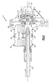
- FIG. 2 is a cross-sectional view of the engine mounted boost pump.
- FIG. 3 is a perspective view of the boost stage impeller.
- FIG. 4 is a front view of the boost stage impeller with front shroud removed.
- FIG. 5 is a perspective view of the boost stage impeller with front shroud removed.
- FIG. 6 is a side view of the boost stage impeller.
- FIG. 7 is a side cross-sectional view of the boost stage impeller.
- FIG. 8 is a front view of the impeller blades showing geometry defining cross sections.
- FIG. 9 is a cross-sectional view through a blade, which illustrates the coordinate system of the disclosure.
- FIG. 1 A schematic of an example of engine mounted fuel delivery system, for example, for an aircraft, is illustrated in FIG. 1 .
- the system 10 includes a fuel inlet 12 that is fluidly connected to airframe plumbing at engine airframe interface. Fuel is delivered to this interface from the aircraft fuel tanks by means of airframe mounted fuel pumps.
- a boost pump 14 pressurizes the fuel before providing the fuel to the main pump 18 .
- a filter 17 and a heat exchanger 16 are installed in between the boost pump 14 and the main pump 18 .
- Fuel from the main pump 18 is regulated by a fuel metering unit 20 , which supplies pressure regulated fuel to the engine 22 .
- FIG. 2 shows a cross-sectional view of an example engine-mounted boost and main fuel pump having the longitudinal axis, which corresponds to an axis Z. Only the boost pump 14 is illustrated in FIG. 2 .
- the boost pump 14 includes a shrouded impeller 24 rotationally driven by a shaft 23 , which is typically driven by a gearbox mounted on the engine.
- the impeller 24 is arranged between a boost housing cover 26 and a center plate 28 .
- Front and rear labyrinth seals 30 , 32 respectively seal between the impeller 24 and the boost housing cover 26 and center plate 28 .
- a rear side face seal 46 is also provided between the center plate 28 and the impeller 24 in the example shown.
- the shaft 23 is splined to a drive gear 34 , which is couple to and rotationally drives a driven gear 36 .
- a drive gear floating bearing 38 and a drive gear fixed bearing 40 support the drive gear 34 .
- a driven gear floating bearing 42 and a driven gear fixed bearing 44 support the driven gear 36 .
- fuel flow enters through the inlet from the far right side opening 45 of the boost pump housing cover 26 flowing axially from left to right.
- the fuel flow then enters first the inducer section 53 of the rotating impeller 24 where the pressure is raised and the eventual air and vapor phase present in the mixture are compressed back in to solution such by the time the fuel flow reaches the impeller section 51 most of the mixture is in the liquid phase.
- the fuel flow then enters the impeller section 51 where the majority of the pressure rise takes place, while the fluid absolute velocity is greatly increased.
- the fuel flow leaves the impeller 24 at its outside diameter exit port, or perimeter 62 , under significantly larger pressure and with large velocity in an almost tangential direction. At this location, the flow stream contains potential energy based on the actual static pressure and a good amount of kinetic energy due to the high flow velocity.
- FIGS. 3-6 show various views of the impeller 24 , which is cast or machined.
- machined impellers are provided by two components in the example, a hub 50 and a shroud 48 .
- the inducer and impeller blades are machined directly in the hub as one piece.
- the shroud 48 is machined separately and attached by brazing to the hub 50 .
- the shroud 48 is provided with a couple of notches as a wrenching feature.
- the impeller section 51 has three sets of blades, a set of main blades 52 , a set of primary splitter blades 54 , and a set of secondary splitter blades 56 .
- the outer ends of these blades are evenly circumferentially spaced from one another at the perimeter 62 , in the example.
- a typical impeller blade works by engaging the incoming flow at the leading edge of the blade with some incidence and by guiding the flow along its length all the way to impeller exit port at the perimeter 62 efficiently and without generating eddies or flow separation.
- the fluid stream is forced by the cascade of blades into a complex rotational motion combined with a longitudinal and radial motion.
- the inertial effects of the centrifugal and Coriolis forces introduced by the forced fluid motion impart pressure into the fluid.
- the impeller section 51 achieves the desired fluid characteristics, in part, by the geometry of the three regions, R 1 , R 2 , R 3 as shown in FIG.
- R 1 is provided circumferentially between the main blades 52 upstream from the primary splitter blades 54
- R 2 is provided circumferentially between the main blades 52 and the primary splitter blades 54
- R 3 is provided circumferentially between the primary splitter blades 54 and the secondary splitter blades 56 .
- the blade surface running against the fluid develops higher pressures at the pressure side, while on the opposite side of the blade a depression is created on the suction side.
- the blade shape and length impart the required amount of work into the fluid with minimum viscous drag and without introducing eddies, or flow separation.
- the inducer section 53 has two sets of blades, a set of inducer main blades 58 , and a set of inducer splitter blades 60 .
- the inducer section 53 is axial as opposed to mostly radial, as in the impeller section 51 .
- the fluid stream guidance and energy transfer mechanism between the inducer section blades and the fluid are similar to those encountered in the impeller section 51 , except for the fact that the calculations are based on a two phase mixture.
- the mixture contains a liquid phase and a gaseous phase, where the gaseous phase contains air and vapor of the fuel. Staring from the opening 45 , the pressure is progressively rising due to the work imposed by the inducer section blades, and consequently the vapor and air present in the gaseous phase are compressed back into solution.
- the hub shape in the inducer section is designed to provide larger volume towards inlet where the specific volume of the two-phase mixture is the smallest.
- the first inducer main blade 58 begins at an inner diameter D 1 and extends radially outwardly to an outer diameter D 4 .
- the impeller main blade 52 begins at an inner diameter D 3 , as shown in FIG. 8 , and extends radially outwardly to an outer diameter D 2 , which corresponds to the perimeter 62 .
- D 4 and D 3 are approximately equal to one another.
- FIG. 8 shows a front view of the impeller blades along with the cross section defining the blade geometry.
- the blade thickness varies along the blade as well as from hub to shroud in a linear progression.
- each cross section has a rectangular shape and is defined by means of numerical coordinates of the four corner points, as explained below with reference to FIG. 9 .
- sections through each blade correspond to the “station numbers” located at a particular angle “theta,” referred to in the Tables.
- the stations for the impeller main blade 52 for the data in Table 1-3 are shown in FIG. 8 .
- the first set of data corresponds to section Mi and continues to the last set of data, Mo, for the impeller main blade 52 .
- the first set of data corresponds to section Pi and continues to the last set of data, Po, for the primary splitter blade 54 ; the first set of data corresponds to section Si and continues to the last set of data, So, for the secondary splitter blade 56 .
- a various number of sections may be used to define a given blade, as is evident by the data in the Tables.
- the coordinates of all the cross sections used to generate the geometry of the blades are listed in a cylindrical coordinate system, which lines up with the impeller and pump axis.
- the four corner points of each cross section are the hub pressure side, hub suction side, shroud pressure side, and shroud suction side based on their physical location.
- the final shape of the blade is obtained by cubic spline interpolation between the corresponding points of all the cross section composing a blade.
- the blade coordinate tables defining the inducer blades and the impeller blades are listed under TABLE N-1 through N-5, where N represents a value and the same values represent a set of data for a given impeller 24 .
- Tables 1-1, 1-2, 1-3, 1-4, 1-5 represent data for one example impeller;
- Tables 2-1, 2-2, 2-3, 2-4, 2-5 represent data for another example impeller;
- Tables 3-1, 3-2, 3-3, 3-4, 3-5 represent data for yet another example impeller.
- Tables N-1 through N-5 defining the inducer and impeller blade geometries are shown in a cylindrical coordinate system for R, theta, and Z, in inches, of each blade surface.
- Tables N-1 is a cylindrical coordinate table defining the inducer main blade 58 geometry.
- Tables N-2 is a cylindrical coordinate table defining the inducer splitter blade 60 geometry.
- Tables N-3 is a cylindrical coordinate table defining the impeller main blade 52 geometry.
- Tables N-4 is a cylindrical coordinate table defining the impeller primary splitter blade 54 geometry.
- Tables N-5 is a cylindrical coordinate table defining the impeller secondary splitter blade 56 geometry. Referring to FIG.
- the “shroud pressure side” corresponds to point A
- the “shroud suction side” corresponds to point B
- the “hub suction side” corresponds to point C
- the “hub pressure side” corresponds to point D.
- points A-D define a quadrilateral cross-section through the respective blade.
- the cylindrical coordinate system Z axis aligns with the impeller 24 axis of rotation, with the Z zero coordinate in the axial plane corresponding with where the main, primary splitter and secondary splitter impeller blades 52 , 54 , 56 intersect the perimeter 62 .
- the positive direction of the Z axis points towards the pump opening 45 .
- the R coordinate corresponds to the distance from the Z axis, and theta is the relative angular position.
- One example impeller 24 includes diameters as follows: D 1 ⁇ 0.5 in (12.7 mm), D 3 ⁇ D 4 ⁇ 2.0 in (50.8 mm), D 2 ⁇ 4.0 in (101.6 mm).
- the data in the Tables corresponds to a ratio between the given R and Z coordinate and the impeller outer diameter D 2 .
- Table values are shown to four decimal places. However, in view of manufacturing constraints, actual values useful for manufacture of the component are considered to be the values to determine the claimed profile. There are typical manufacturing tolerances, which must be accounted for in the profile. Accordingly, the Table coordinate values are for nominal component. It will therefore be appreciated that plus or minus typical manufacturing tolerances are applicable to the Table coordinate values and that a component having a profile substantially in accordance with those values includes tolerances. For example, a manufacturing tolerance of about +/ ⁇ 0.010 inches on surface profile should be considered within the design limits for the component. Thus, the mechanical and aerodynamic functions of the component are not impaired by manufacturing imperfections and tolerances, which in different embodiments may be greater or lesser than the values set forth in the disclosed Tables. As appreciated by those skilled in the art, manufacturing tolerances may be determined to achieve a desired mean and standard deviation of manufactured components in relation to the ideal component profile points set forth in the disclosed Tables.
Landscapes
- Engineering & Computer Science (AREA)
- Mechanical Engineering (AREA)
- General Engineering & Computer Science (AREA)
- Physics & Mathematics (AREA)
- Geometry (AREA)
- Structures Of Non-Positive Displacement Pumps (AREA)
Priority Applications (2)
| Application Number | Priority Date | Filing Date | Title |
|---|---|---|---|
| US13/351,900 US8944767B2 (en) | 2012-01-17 | 2012-01-17 | Fuel system centrifugal boost pump impeller |
| CN201310016922.7A CN103206404B (zh) | 2012-01-17 | 2013-01-17 | 燃料系统离心增压泵叶轮 |
Applications Claiming Priority (1)
| Application Number | Priority Date | Filing Date | Title |
|---|---|---|---|
| US13/351,900 US8944767B2 (en) | 2012-01-17 | 2012-01-17 | Fuel system centrifugal boost pump impeller |
Publications (2)
| Publication Number | Publication Date |
|---|---|
| US20130183155A1 US20130183155A1 (en) | 2013-07-18 |
| US8944767B2 true US8944767B2 (en) | 2015-02-03 |
Family
ID=48753751
Family Applications (1)
| Application Number | Title | Priority Date | Filing Date |
|---|---|---|---|
| US13/351,900 Active 2033-08-26 US8944767B2 (en) | 2012-01-17 | 2012-01-17 | Fuel system centrifugal boost pump impeller |
Country Status (2)
| Country | Link |
|---|---|
| US (1) | US8944767B2 (nl) |
| CN (1) | CN103206404B (nl) |
Cited By (7)
| Publication number | Priority date | Publication date | Assignee | Title |
|---|---|---|---|---|
| US20150114477A1 (en) * | 2012-04-18 | 2015-04-30 | Eaton Limited | Aircraft fuel supply systems |
| US20160097399A1 (en) * | 2014-10-06 | 2016-04-07 | Hamilton Sundstrand Corporation | Volute for engine-mounted boost stage fuel pump |
| US20160097400A1 (en) * | 2014-10-06 | 2016-04-07 | Hamilton Sundstrand Corporation | Impeller for engine-mounted boost stage fuel pump |
| US20170097008A1 (en) * | 2015-10-02 | 2017-04-06 | Sundyne, Llc | Low-Cavitation Impeller and Pump |
| US10371151B2 (en) * | 2014-01-12 | 2019-08-06 | Alfa Corporate Ab | Self-priming centrifugal pump |
| US10422337B2 (en) | 2014-01-12 | 2019-09-24 | Alfa Laval Corporate Ab | Self-priming centrifugal pump |
| US10458431B2 (en) * | 2017-04-10 | 2019-10-29 | Hamilton Sundstrand Corporation | Volutes for engine mounted boost stages |
Families Citing this family (16)
| Publication number | Priority date | Publication date | Assignee | Title |
|---|---|---|---|---|
| US10125771B2 (en) * | 2014-09-03 | 2018-11-13 | Uchicago Argonne, Llc | Compact liquid nitrogen pump |
| CN105697389A (zh) * | 2014-12-11 | 2016-06-22 | 德昌电机(深圳)有限公司 | 泵及清洗装置 |
| CN105275499B (zh) * | 2015-06-26 | 2016-11-30 | 中航空天发动机研究院有限公司 | 一种具有离心增压和封严效果的双辐板涡轮盘盘心进气结构 |
| JPWO2017057481A1 (ja) * | 2015-10-02 | 2018-07-12 | 株式会社Ihi | インペラおよび過給機 |
| CN105604974A (zh) * | 2015-12-29 | 2016-05-25 | 西安航天动力研究所 | 离心泵轮密封结构 |
| CN105545797A (zh) * | 2015-12-29 | 2016-05-04 | 西安航天动力研究所 | 高抗汽蚀性能一体化叶轮 |
| US11193493B2 (en) * | 2016-07-04 | 2021-12-07 | Amotech Co., Ltd. | Water pump |
| CZ307489B6 (cs) * | 2017-03-10 | 2018-10-10 | Česká zemědělská univerzita v Praze | Úprava spirální skříně odstředivého čerpadla |
| US10323648B2 (en) * | 2017-04-07 | 2019-06-18 | Hamilton Sundstrand Corporation | Impellers for engine mounted boost stage pumps |
| WO2019035493A1 (ko) * | 2017-08-14 | 2019-02-21 | 주식회사 에스 피 지 | 레이디얼 팬 |
| CN107989823B (zh) * | 2017-12-26 | 2023-12-01 | 北京伯肯节能科技股份有限公司 | 叶轮、离心压缩机及燃料电池系统 |
| USD940760S1 (en) * | 2020-04-04 | 2022-01-11 | Colina | Mixing pump impeller |
| USD958842S1 (en) * | 2020-04-04 | 2022-07-26 | Colina | Mixing pump impeller vane assembly |
| CN112412870B (zh) * | 2020-10-30 | 2022-10-11 | 中国航发西安动力控制科技有限公司 | 一种增压泵叶轮 |
| JP7713782B2 (ja) * | 2021-02-22 | 2025-07-28 | 株式会社小松製作所 | ターボ型ポンプ及び流体供給ユニット |
| CN114396383A (zh) * | 2022-01-10 | 2022-04-26 | 成都凯天电子股份有限公司 | 一种油汽混输系统 |
Citations (17)
| Publication number | Priority date | Publication date | Assignee | Title |
|---|---|---|---|---|
| US3163119A (en) * | 1961-07-03 | 1964-12-29 | North American Aviation Inc | Inducer |
| US4142839A (en) * | 1975-02-03 | 1979-03-06 | Lear Siegler, Inc. | Centrifugal pump for high V/L performance |
| US4687412A (en) | 1985-07-03 | 1987-08-18 | Pratt & Whitney Canada Inc. | Impeller shroud |
| US5100295A (en) * | 1988-09-16 | 1992-03-31 | Nnc Limited | Impeller pumps |
| US5152661A (en) | 1988-05-27 | 1992-10-06 | Sheets Herman E | Method and apparatus for producing fluid pressure and controlling boundary layer |
| US5527149A (en) | 1994-06-03 | 1996-06-18 | Coltec Industries Inc. | Extended range regenerative pump with modified impeller and/or housing |
| US6422808B1 (en) | 1994-06-03 | 2002-07-23 | Borgwarner Inc. | Regenerative pump having vanes and side channels particularly shaped to direct fluid flow |
| US6551054B1 (en) * | 1998-12-30 | 2003-04-22 | Sulzer Pumpen Ag | Method and apparatus for pumping a material and a rotor for use in connection therewith |
| US6632071B2 (en) | 2000-11-30 | 2003-10-14 | Lou Pauly | Blower impeller and method of lofting their blade shapes |
| US6935840B2 (en) | 2002-07-15 | 2005-08-30 | Pratt & Whitney Canada Corp. | Low cycle fatigue life (LCF) impeller design concept |
| US7070388B2 (en) | 2004-02-26 | 2006-07-04 | United Technologies Corporation | Inducer with shrouded rotor for high speed applications |
| US7189056B2 (en) | 2005-05-31 | 2007-03-13 | Pratt & Whitney Canada Corp. | Blade and disk radial pre-swirlers |
| US7201565B2 (en) * | 2004-07-06 | 2007-04-10 | Hon Hai Precision Industry Co., Ltd. | Fan blade set for cooling fan |
| US7273352B2 (en) * | 2004-01-09 | 2007-09-25 | United Technologies Corporation | Inlet partial blades for structural integrity and performance |
| US7293958B2 (en) | 2004-03-05 | 2007-11-13 | Aweco Appliance Systems Gmbh & Co. Kg | Centrifugal pump |
| US7455497B2 (en) * | 2003-12-05 | 2008-11-25 | Carter Cryogenics Company, Llc | High performance inducer |
| US7572105B2 (en) | 2006-10-25 | 2009-08-11 | General Electric Company | Airfoil shape for a compressor |
Family Cites Families (1)
| Publication number | Priority date | Publication date | Assignee | Title |
|---|---|---|---|---|
| US4120603A (en) * | 1977-03-28 | 1978-10-17 | General Motors Corporation | Jet flap controlled fuel pump |
-
2012
- 2012-01-17 US US13/351,900 patent/US8944767B2/en active Active
-
2013
- 2013-01-17 CN CN201310016922.7A patent/CN103206404B/zh active Active
Patent Citations (17)
| Publication number | Priority date | Publication date | Assignee | Title |
|---|---|---|---|---|
| US3163119A (en) * | 1961-07-03 | 1964-12-29 | North American Aviation Inc | Inducer |
| US4142839A (en) * | 1975-02-03 | 1979-03-06 | Lear Siegler, Inc. | Centrifugal pump for high V/L performance |
| US4687412A (en) | 1985-07-03 | 1987-08-18 | Pratt & Whitney Canada Inc. | Impeller shroud |
| US5152661A (en) | 1988-05-27 | 1992-10-06 | Sheets Herman E | Method and apparatus for producing fluid pressure and controlling boundary layer |
| US5100295A (en) * | 1988-09-16 | 1992-03-31 | Nnc Limited | Impeller pumps |
| US5527149A (en) | 1994-06-03 | 1996-06-18 | Coltec Industries Inc. | Extended range regenerative pump with modified impeller and/or housing |
| US6422808B1 (en) | 1994-06-03 | 2002-07-23 | Borgwarner Inc. | Regenerative pump having vanes and side channels particularly shaped to direct fluid flow |
| US6551054B1 (en) * | 1998-12-30 | 2003-04-22 | Sulzer Pumpen Ag | Method and apparatus for pumping a material and a rotor for use in connection therewith |
| US6632071B2 (en) | 2000-11-30 | 2003-10-14 | Lou Pauly | Blower impeller and method of lofting their blade shapes |
| US6935840B2 (en) | 2002-07-15 | 2005-08-30 | Pratt & Whitney Canada Corp. | Low cycle fatigue life (LCF) impeller design concept |
| US7455497B2 (en) * | 2003-12-05 | 2008-11-25 | Carter Cryogenics Company, Llc | High performance inducer |
| US7273352B2 (en) * | 2004-01-09 | 2007-09-25 | United Technologies Corporation | Inlet partial blades for structural integrity and performance |
| US7070388B2 (en) | 2004-02-26 | 2006-07-04 | United Technologies Corporation | Inducer with shrouded rotor for high speed applications |
| US7293958B2 (en) | 2004-03-05 | 2007-11-13 | Aweco Appliance Systems Gmbh & Co. Kg | Centrifugal pump |
| US7201565B2 (en) * | 2004-07-06 | 2007-04-10 | Hon Hai Precision Industry Co., Ltd. | Fan blade set for cooling fan |
| US7189056B2 (en) | 2005-05-31 | 2007-03-13 | Pratt & Whitney Canada Corp. | Blade and disk radial pre-swirlers |
| US7572105B2 (en) | 2006-10-25 | 2009-08-11 | General Electric Company | Airfoil shape for a compressor |
Cited By (14)
| Publication number | Priority date | Publication date | Assignee | Title |
|---|---|---|---|---|
| US9556838B2 (en) * | 2012-04-18 | 2017-01-31 | Eaton Limited | Aircraft fuel supply systems |
| US20150114477A1 (en) * | 2012-04-18 | 2015-04-30 | Eaton Limited | Aircraft fuel supply systems |
| US10371151B2 (en) * | 2014-01-12 | 2019-08-06 | Alfa Corporate Ab | Self-priming centrifugal pump |
| US10422337B2 (en) | 2014-01-12 | 2019-09-24 | Alfa Laval Corporate Ab | Self-priming centrifugal pump |
| US20160097399A1 (en) * | 2014-10-06 | 2016-04-07 | Hamilton Sundstrand Corporation | Volute for engine-mounted boost stage fuel pump |
| US20160097400A1 (en) * | 2014-10-06 | 2016-04-07 | Hamilton Sundstrand Corporation | Impeller for engine-mounted boost stage fuel pump |
| US9546625B2 (en) * | 2014-10-06 | 2017-01-17 | Hamilton Sundstrand Corporation | Volute for engine-mounted boost stage fuel pump |
| US9562502B2 (en) * | 2014-10-06 | 2017-02-07 | Hamilton Sundstrand Corporation | Impeller for engine-mounted boost stage fuel pump |
| US20170097008A1 (en) * | 2015-10-02 | 2017-04-06 | Sundyne, Llc | Low-Cavitation Impeller and Pump |
| JP2018529880A (ja) * | 2015-10-02 | 2018-10-11 | サンダイン エルエルシー | 低キャビテーションのインペラおよびポンプ |
| RU2681868C1 (ru) * | 2015-10-02 | 2019-03-13 | Сандайн, Ллс | Насос и импеллер с низкой кавитацией |
| US10001133B2 (en) * | 2015-10-02 | 2018-06-19 | Sundyne, Llc | Low-cavitation impeller and pump |
| WO2017059074A1 (en) * | 2015-10-02 | 2017-04-06 | Sundyne, Llc | Low-cavitation impeller and pump |
| US10458431B2 (en) * | 2017-04-10 | 2019-10-29 | Hamilton Sundstrand Corporation | Volutes for engine mounted boost stages |
Also Published As
| Publication number | Publication date |
|---|---|
| US20130183155A1 (en) | 2013-07-18 |
| CN103206404B (zh) | 2015-11-18 |
| CN103206404A (zh) | 2013-07-17 |
Similar Documents
| Publication | Publication Date | Title |
|---|---|---|
| US8944767B2 (en) | Fuel system centrifugal boost pump impeller | |
| US10323648B2 (en) | Impellers for engine mounted boost stage pumps | |
| US9546625B2 (en) | Volute for engine-mounted boost stage fuel pump | |
| US10458431B2 (en) | Volutes for engine mounted boost stages | |
| US9562502B2 (en) | Impeller for engine-mounted boost stage fuel pump | |
| EP2896807B1 (en) | Turbocharger with twin parallel compressor impellers and having center housing features for conditioning flow in the rear impeller | |
| CN110388283A (zh) | 气体涡轮机引擎 | |
| US10519774B2 (en) | Rotor arrangement for a turbomachine and compressor | |
| US8974178B2 (en) | Fuel system centrifugal boost pump volute | |
| JP2015166593A (ja) | 可変容量型ベーンポンプを用いるダイレクト計量 | |
| CN103016069B (zh) | 空气循环机、用于其的涡轮喷嘴及涡轮喷嘴安装方法 | |
| US20170298742A1 (en) | Turbine engine airfoil bleed pumping | |
| CN111503063B (zh) | 具有射流泵的发电机 | |
| CN110273714B (zh) | 用于翼型件的套环支撑组件 | |
| US20120156018A1 (en) | Turbine shroud for air cycle machine | |
| US20170306972A1 (en) | Centrifugal compressor | |
| US11421702B2 (en) | Impeller with chordwise vane thickness variation | |
| US10844736B2 (en) | Straightener vane and structural arm connected in a primary flow path | |
| JP2011027101A (ja) | ターボポンプ | |
| US11781504B2 (en) | Bleed plenum for compressor section | |
| US11933295B2 (en) | Tapered shafts for fluid pumps | |
| Sperber | Development of a Machine Concept | |
| US20250172095A1 (en) | Turbomachine with axial thrust management | |
| US10280934B2 (en) | Gas turbine compressor stage | |
| IT202300001953A1 (it) | Turbomacchina pluristadio con flusso laterale |
Legal Events
| Date | Code | Title | Description |
|---|---|---|---|
| AS | Assignment |
Owner name: HAMILTON SUNDSTRAND CORPORATION, CONNECTICUT Free format text: ASSIGNMENT OF ASSIGNORS INTEREST;ASSIGNORS:STOICESCU, ADRIAN L.;HEITZ, STEVEN A.;REEL/FRAME:027543/0984 Effective date: 20120117 |
|
| STCF | Information on status: patent grant |
Free format text: PATENTED CASE |
|
| MAFP | Maintenance fee payment |
Free format text: PAYMENT OF MAINTENANCE FEE, 4TH YEAR, LARGE ENTITY (ORIGINAL EVENT CODE: M1551) Year of fee payment: 4 |
|
| MAFP | Maintenance fee payment |
Free format text: PAYMENT OF MAINTENANCE FEE, 8TH YEAR, LARGE ENTITY (ORIGINAL EVENT CODE: M1552); ENTITY STATUS OF PATENT OWNER: LARGE ENTITY Year of fee payment: 8 |