US8931318B2 - Device and method for the surface peening of a component of a gas turbine - Google Patents
Device and method for the surface peening of a component of a gas turbine Download PDFInfo
- Publication number
- US8931318B2 US8931318B2 US12/448,056 US44805607A US8931318B2 US 8931318 B2 US8931318 B2 US 8931318B2 US 44805607 A US44805607 A US 44805607A US 8931318 B2 US8931318 B2 US 8931318B2
- Authority
- US
- United States
- Prior art keywords
- peening
- component
- rotor
- chamber
- vibration means
- Prior art date
- Legal status (The legal status is an assumption and is not a legal conclusion. Google has not performed a legal analysis and makes no representation as to the accuracy of the status listed.)
- Expired - Fee Related, expires
Links
Images


Classifications
-
- B—PERFORMING OPERATIONS; TRANSPORTING
- B24—GRINDING; POLISHING
- B24C—ABRASIVE OR RELATED BLASTING WITH PARTICULATE MATERIAL
- B24C1/00—Methods for use of abrasive blasting for producing particular effects; Use of auxiliary equipment in connection with such methods
- B24C1/10—Methods for use of abrasive blasting for producing particular effects; Use of auxiliary equipment in connection with such methods for compacting surfaces, e.g. shot-peening
-
- B—PERFORMING OPERATIONS; TRANSPORTING
- B24—GRINDING; POLISHING
- B24C—ABRASIVE OR RELATED BLASTING WITH PARTICULATE MATERIAL
- B24C5/00—Devices or accessories for generating abrasive blasts
- B24C5/005—Vibratory devices, e.g. for generating abrasive blasts by ultrasonic vibrations
-
- Y—GENERAL TAGGING OF NEW TECHNOLOGICAL DEVELOPMENTS; GENERAL TAGGING OF CROSS-SECTIONAL TECHNOLOGIES SPANNING OVER SEVERAL SECTIONS OF THE IPC; TECHNICAL SUBJECTS COVERED BY FORMER USPC CROSS-REFERENCE ART COLLECTIONS [XRACs] AND DIGESTS
- Y10—TECHNICAL SUBJECTS COVERED BY FORMER USPC
- Y10T—TECHNICAL SUBJECTS COVERED BY FORMER US CLASSIFICATION
- Y10T29/00—Metal working
- Y10T29/47—Burnishing
- Y10T29/479—Burnishing by shot peening or blasting
Definitions
- the invention relates to a device for surface-peening, especially for the ultrasound shot-peening of a component of a gas turbine, having at least one vibration means that comprises a surface that propels the peening material, and having a holding means with which a surface area of the component and the surface of the vibration means can be arranged with respect to each other and to a method for surface-peening, especially for the ultrasound shot-peening of a component of a gas turbine in which a surface area of the component and at least one surface of the vibration means that propels the peening material are arranged with respect to each other and can be moved with respect to each other during the surface-peening.
- Such a device and such a method are already known as prior art from European patent application EP 1 101 568 B1, whereby the rotor blades of a rotor configured as a blisk can be shot-peened for purposes of improving their fatigue strength.
- the device here comprises a holding means on which the rotor is held so as to be rotatable around its rotational axis. As the rotor turns, its blades pass through a peening chamber at the bottom of which there is a vibration means in the form of an ultrasound sonotrode having at least one vibrating surface that runs approximately horizontally.
- the peening chamber is delimited axially—that is to say, in the area of the wide sides of the rotor—as well as radially—in other words, in the area of the rotor blades of the blisk—by corresponding chamber walls. Since, depending on the position of each of the rotor blades, especially the walls of the peening chamber arranged radially with respect to the rotor are not capable of holding all of the balls inside the central peening chamber, two additional chambers are arranged upstream or downstream from the central peening chamber in the radial direction of the rotor. Balls that overflow from the central peening chamber fitted with the sonotrode are collected inside these additional chambers and returned via appropriate channels.
- the objective of the present invention is to create a device as well as a method of the above-mentioned type by means of which various surface areas of the component can be hardened more systematically and more uniformly.
- the angular position of the surface of the at least one vibration means can be adjusted relative to the surface area of the component of the gas turbine.
- the angular position of the surface of the vibration means can be adjusted relative to the surface area of the component before and/or during the surface-peening.
- a device as well as a method for surface-peening are created with which the angular positions of the surface of the at least one vibration means and of the surface area of the component can be adjusted relative to each other in such a way that the specific surface area that is to be worked can be optimally peened with peening material. Since, for example, the twist of each rotor blade around its center axis or its perpendicular to the rotational axis of the rotor causes the vector of the surface normal to change markedly over the geometry of the blade, the fact that the surface of the vibration means can be adjusted now makes it possible to correspondingly adjust its normal vector.
- the surface of the vibration means for instance, can now be adjusted in such a way that its normal vector—directly or at the desired angle—faces the surface area of the component that is to be worked. Since the angle at which the peening material is propelled from the surface of the vibration means against the surface area of the component that is to be worked has a decisive influence on the extent of the hardening, the latter can be systematically and uniformly adjusted by appropriately adjusting the angular position of the surface of the vibration means.
- the surface quality or the hardening of the surface area of the component to be worked can be reproduced very accurately. In other words, it can be ensured that the peening intensity of the surface-peening remains extremely homogenous within very narrow limits over the entire peening area.
- the angular position of the surface of the at least one vibration means can be adjusted relative to the surface area during the surface-peening of the surface area of the component.
- various surface areas of the component can be worked individually by means of a surface-peening that is harmonized with said areas. Since, in each case, the angular position of the surface of the vibration means can be adjusted relative to the surface area that is to be worked, the peening intensity and the striking angle of the peening material can be harmonized with the surface area of the component that is to be worked.
- the rotor blades can be peened in a continuous or multiple-step process in that the rotor is turned at a certain speed. Consequently, the angular position of the surface of the vibration means changes as it adapts to the speed.
- two vibration means are provided which each have surfaces that are at an angle relative to each other. This makes it easy to work a component on both sides simultaneously, so that even complex three-dimensional component geometries can be peened in an optimal manner.
- the simultaneous surface-peening on both sides entails the major advantage that, in particular, thin areas of the component do not become warped.
- the appertaining surfaces of the two vibration means it has also proven to be advantageous for the appertaining surfaces of the two vibration means to be arranged so as to be essentially in a V-shape with respect to each other.
- the angular positions of these two surfaces can be adapted to each other very easily so that, especially in the case of peening on both sides, the surface areas that are directly across from each other can be peened simultaneously.
- a mirror-symmetrical arrangement provides that the appertaining surfaces of the two vibration means intersect each other at least approximately in a center axis or in a perpendicular of the component.
- the at least one adjustable surface of each vibration means can be adjusted around one or two adjustment axes. These two axes run preferably perpendicular to each other, so that a tilt angle and a rotational angle can easily be set.
- a surface of a vibration means that has two adjustment axes is thus especially characterized in that it can be adjusted two-dimensionally. Consequently, of course, the normal vector of the surface can also be adjusted two-dimensionally.
- the device according to the invention has proven to be advantageous especially in order to peen a rotor, particularly a blisk, that is held so that it can rotate around its rotational axis.
- a rotor particularly a blisk
- the rotor blades can thus be easily brought into the peening area of the vibration means by turning the rotor, whereby the adjustable surface ensures that all of the surface areas that are to be worked are impinged with the desired peening intensity.
- the peening chamber can be easily adapted to the specific component that is to be worked in that its chamber walls are designed so as to be flexible, at least in certain areas.
- a flexible jacket makes it possible, for example, to surround the entire component, thus preventing the loss of peening material.
- flexible chamber walls ensure that they can easily fit closely against the sonotrode and against the component holder, so that here as well, there is no need to fear any loss of peening material.
- a distribution means is provided with which the peening material can be distributed over the surface of the vibration means. Owing to the slanted arrangement of the surface, it is prevented in a simple manner that peening material accumulates excessively at a low point of the surface. Instead, the distribution means can achieve a uniform distribution of the peening material, resulting in a uniform peening intensity over the entire surface and a uniform hardening of the surface area of the component.
- the distribution means can also be operated with a compressed medium, especially with pressurized air, which can easily be adjusted in such a way that the peening material is uniformly distributed, also on the top places of the surface of the vibration means.
- a first means for determining the quantity of peening material is provided inside the peening chamber.
- This means can perform, for instance, a sound analysis inside the peening chamber by means of which the quantity of peening material can be determined. This makes use of the underlying notion that the sound made by the peening material changes as a function of its quantity.
- a means for refilling the peening material can be provided so as to keep the quantity of peening material constant inside the peening chamber.
- a uniform quantity of peening material ensures that the peening results are easily reproducible and constant.
- the means for refilling the peening material can be controlled as a function of the quantity of peening material determined by the first means. In this manner, it is easy to perform monitoring, so that the same quantity of peening material is always present, for example, inside the peening chamber.
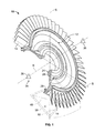
- FIG. 1 a schematic perspective view of a rotor of a gas turbine—in the form of a blisk—depicted as a cutaway section that is held by means of a merely schematically indicated holding means so as to be rotatable around its rotational axis, whereby, on the bottom of the blisk in the area of the rotor blades, a schematically indicated peening chamber can be seen that comprises two surfaces—arranged in a V-shape with respect to each other—of associated vibration means with which peening material, for example, in the form of balls, can be propelled in the direction of the rotor blades; and in
- FIG. 2 a schematic sectional view through the blisk according to FIG. 1 , whereby, in the area of the rotor blades, the device for surface-peening is depicted that here comprises two surfaces—arranged in a V-shape with respect to each other—of each of the vibration means, whereby the angular positions of these two surfaces can be adjusted relative to the blisk.
- FIG. 1 schematically shows a schematic and sectional perspective view of a rotatable rotor on a gas turbine in the form of a blisk 10 .
- the basic individual areas of the blisk 10 can be seen in greater detail in conjunction with FIG. 2 , which shows a schematic sectional view of said blisk 10 .
- a blisk disk 12 can be clearly seen on whose outer circumference numerous rotor blades 14 are arranged.
- a platform 16 shown in the form of a line in FIG. 2 —can be seen on the outer circumference of the blisk disk 12 and this platform 16 is followed radially towards the inside, or upwards in the drawing, by a sub-platform area 18 .
- This sub-platform area 18 makes a transition radially inwards into a disk neck 20 that connects the sub-platform area 18 to a disk element 22 .
- the radial inner end of the disk element 22 is formed by a hub 24 that constitutes a counterweight to the rotor blades 14 .
- a first wing 26 whose cross section is essentially angular, projects from the sub-platform area 18 or from the disk neck 20 on one side of the blisk disk 12 .
- another wing 28 projects from the other side of the blisk disk 12 , said wing comprising an angular area 30 as well as a web 32 that connects this area to the disk element 22 , said web projecting at an angle of 45° relative to the disk element 22 .
- the blisk 10 is configured to be rotatable around a rotational axis R or to be rotation-symmetrical.
- FIG. 1 shows a holding means 34 symbolically indicated by two bearing blocks 36 , by means of which the blisk is held or mounted so as to be rotatable around its rotational axis R.
- the shot-peening device here comprises a peening chamber 38 that can be seen in greater detail, especially when viewed in conjunction with FIG. 2 .
- the peening chamber 38 serves to shot-peen the surface areas 40 , 42 on the opposite sides of each of the rotor blades 14 .
- the peening chamber 38 is only indicated by broken lines and shown in a cutaway view along a perpendicular S on the rotational axis R of the blisk 10 or parallel to the sectional surface through the blisk 10 .
- the peening chamber 38 comprises two vibration means 44 , 46 —indicated merely schematically—that are configured here as ultrasound sonotrodes.
- Each of the vibration means 44 , 46 has a surface 48 , 50 that faces the component to be peened or the appertaining rotor blade 14 , said surfaces 48 , 50 being configured flat in the present embodiment.
- the surfaces 48 , 50 of the two vibration means 44 , 46 are arranged essentially V-shaped with respect to each other, at an angle here of about 110° to 120°.
- the two vibration means 44 , 46 are accommodated inside appertaining chamber walls 52 , 54 of the peening chamber 38 .
- chamber walls 52 , 54 that accommodate the vibration means 44 , 46 are followed at an angle by corresponding additional chamber walls 56 , 58 that close off the peening chamber 38 towards the top. Furthermore, on both faces 60 , chamber walls (not shown here) are provided that at least largely close off the peening chamber 38 in the radial direction of the blisk 10 .
- each of the two surfaces 48 , 50 can be adjusted with respect to each other or to the component (rotor blades 14 ) that are to be worked.
- the adjustment axis V runs perpendicular to the plane of the page.
- each of the two surfaces 50 can be adjusted around another adjustment axis Z that is only schematically indicated in FIG. 2 .
- the second adjustment axes Z each run in the plane of the surfaces 48 , 50 and perpendicular to the first adjustment axis V.
- each of the two surfaces 48 , 50 here are adjusted at least around the adjustment axis V and optionally—if present—around the additional adjustment axis Z.
- the rotor blades 14 each have a twist which, at different partial areas of their surface areas 40 , 42 , causes the vector of the surface normals to change markedly over the blade geometry, said change can be compensated for by appropriately adjusting the angle of the two surfaces 48 , 50 of the two vibration means 44 , 46 .
- the striking angle of the peening material can be adjusted to the partial surface areas 40 , 42 to be peened, thus achieving optimal or individual hardening.
- the angular position of the surfaces 48 , 50 can be adjusted during the surface-peening of the rotor blade 14 in question, so that each rotor blade 14 can be surface-peened in a single work step. If the blisk 10 is rotated stepwise or continuously around its rotational axis R inside the holding means, then an adjustment can likewise be carried out by via the surfaces 48 , 50 .
- the chamber walls 56 , 58 that are located opposite from the surfaces 48 , 50 can likewise be configured so as to be adjustable in order to allow an appropriate adaptation to the slanted positioning of the vibration means 44 , 46 .
- adjustable chamber walls 56 , 58 can be employed to influence the deflection angle at which the peening material rebounds from the walls.
- the V-arrangement of the two surfaces 48 , 50 it is possible, in particular, to simultaneously peen opposite surface areas 40 , 42 of the appertaining rotor blades 14 . As a result, warping is prevented, especially in the case of components having fairly thin walls.
- the adjustment of the angular positions of the surfaces 48 , 50 makes it possible to achieve a homogenous peening intensity over the entire peening area within narrow limits.
- the surfaces 48 , 50 are arranged at an identical angle relative to the perpendicular S, which constitutes a center axis through the appertaining rotor blade 14 .
- the two surfaces 48 , 50 can theoretically be set at an angle ranging from 0° to 90°, especially from 0° to 80°, relative to the perpendicular S or to the center axis of the appertaining rotor blades 14 .
- An angle of the two surfaces 48 , 50 with respect to the perpendicular S that is likewise well-suited is between about 30° and 60°, especially between 40° and 50°.
- a distribution means 62 is provided with which the peening material—primarily the balls—can be uniformly distributed over the two surfaces 48 , 50 .
- the distribution means 62 comprises a hose 64 through which pressurized air or compressed air can be fed in at the lowest point in the peening chamber 38 , so that peening material that is accumulating there can be moved upwards and uniformly distributed over the surfaces 48 , 50 .
- a vibrating surface 66 can also be provided, which is likewise schematically indicated in FIG. 2 .
- the vibrating surface 66 can be operated by a sonotrode, a flapper, a piezo shaker or a vibrating plate or membrane. The result is that the peening material is uniformly distributed over the surfaces 48 , 50 .
- a first means 68 with which the quantity of peening material can be ascertained is provided inside the peening chamber 38 . This can be done, for instance, on the basis of a sound analysis in which the sound in the peening chamber 38 is measured as a function of the quantity of peening material. When the value falls below a given threshold limit, additional peening material can be refilled with a second means 70 , as indicated by the hose 72 drawn with a broken line. The result is that a constant quantity of peening material is always present inside the peening chamber 38 , so that the peening results obtained are reproducible.
- the surface areas 40 , 42 of the component 14 and the surfaces 48 , 50 of the vibration means 44 , 46 can be arranged relative to other by means of the holding means 32 and can be moved relative to each other by rotating the blisk 10 around its rotational axis R during the surface-peening.
- the angular position of the surface 48 , 50 of the at least one vibration means 44 , 46 relative to surface area 40 , 42 of the component 14 can be adjusted either only in advance and/or during the surface-peening of the surface area 40 , 42 of the component 14 so that the surface areas 40 , 42 can be hardened systematically and uniformly.
Landscapes
- Engineering & Computer Science (AREA)
- Mechanical Engineering (AREA)
- Turbine Rotor Nozzle Sealing (AREA)
- Finish Polishing, Edge Sharpening, And Grinding By Specific Grinding Devices (AREA)
- Cleaning Or Drying Semiconductors (AREA)
Abstract
Description
Claims (12)
Applications Claiming Priority (4)
| Application Number | Priority Date | Filing Date | Title |
|---|---|---|---|
| DE102006058679.4 | 2006-12-13 | ||
| DE102006058679 | 2006-12-13 | ||
| DE102006058679A DE102006058679A1 (en) | 2006-12-13 | 2006-12-13 | Device and method for surface blasting of a component of a gas turbine |
| PCT/DE2007/002195 WO2008071161A1 (en) | 2006-12-13 | 2007-12-05 | Device and method for the surface peening of a component of a gas turbine |
Publications (2)
| Publication Number | Publication Date |
|---|---|
| US20100037669A1 US20100037669A1 (en) | 2010-02-18 |
| US8931318B2 true US8931318B2 (en) | 2015-01-13 |
Family
ID=39247146
Family Applications (1)
| Application Number | Title | Priority Date | Filing Date |
|---|---|---|---|
| US12/448,056 Expired - Fee Related US8931318B2 (en) | 2006-12-13 | 2007-12-05 | Device and method for the surface peening of a component of a gas turbine |
Country Status (6)
| Country | Link |
|---|---|
| US (1) | US8931318B2 (en) |
| EP (1) | EP2117777B1 (en) |
| AT (1) | ATE499183T1 (en) |
| CA (1) | CA2672149A1 (en) |
| DE (2) | DE102006058679A1 (en) |
| WO (1) | WO2008071161A1 (en) |
Families Citing this family (3)
| Publication number | Priority date | Publication date | Assignee | Title |
|---|---|---|---|---|
| GB0902333D0 (en) | 2009-02-13 | 2009-04-01 | Rolls Royce Plc | A surface treatment device |
| DE102009015160A1 (en) | 2009-03-26 | 2010-09-30 | Bayerische Motoren Werke Aktiengesellschaft | Process for producing a coated and / or available sheet metal part with a corrosion protection coating |
| CN115179178B (en) * | 2022-07-05 | 2023-11-14 | 华东理工大学 | Water jet strengthening and polishing integrated system and method for blade of impeller |
Citations (18)
| Publication number | Priority date | Publication date | Assignee | Title |
|---|---|---|---|---|
| US4432220A (en) * | 1981-09-10 | 1984-02-21 | United Technologies Corporation | Shot peening apparatus |
| FR2689431A1 (en) | 1992-04-06 | 1993-10-08 | Teknoson | Method and device especially for ultrasonic hardening of metal parts |
| EP1101568A1 (en) | 1999-11-18 | 2001-05-23 | Snecma Moteurs | Method and apparatus for blasting of wheel-like workpieces using ultrasound |
| WO2002024411A1 (en) | 2000-09-21 | 2002-03-28 | Snecma Moteurs | Transverse ultrasound peening of blades on a rotor |
| US6490899B2 (en) * | 2000-11-16 | 2002-12-10 | Snecma Moteurs | Method and apparatus for peening tops of cooled blades |
| US6517319B2 (en) * | 2000-09-22 | 2003-02-11 | Rolls-Royce Plc | Gas turbine engine rotor blades |
| WO2005123338A1 (en) | 2004-06-19 | 2005-12-29 | Mtu Aero Engines Gmbh | Method and device for surface blasting gas turbine blades in the area of the roots thereof |
| EP1623794A1 (en) | 2004-08-05 | 2006-02-08 | MTU Aero Engines GmbH | Device for peening workpiece surfaces |
| US7028378B2 (en) * | 2000-10-12 | 2006-04-18 | Sonats-Societe Des Nouvelles Applications Des Techniques De Surfaces | Method of shot blasting and a machine for implementing such a method |
| US20060252357A1 (en) | 2005-05-09 | 2006-11-09 | Gunther Bohler Gmbh | Device for abrasive-blasting of workpieces |
| US7644599B2 (en) * | 2004-12-10 | 2010-01-12 | Mtu Aero Engines Gmbh | Method for surface blasting cavities, particularly cavities in gas turbines |
| US7647801B2 (en) * | 2004-07-30 | 2010-01-19 | Snecma | Shot, devices, and installations for ultrasonic peening, and parts treated thereby |
| US7691211B2 (en) * | 2000-07-28 | 2010-04-06 | Universite De Technologie De Troyes | Method for generating nanostructures and device for generating nanostructures |
| US7703312B2 (en) * | 2004-01-15 | 2010-04-27 | Siement Aktiengesellschaft | Component with compressive residual stresses, process for producing and apparatus for generating compressive residual stresses |
| US20100125990A1 (en) * | 2006-12-13 | 2010-05-27 | Mtu Aero Engines Gmbh | Method and device for the surface peening of a partial element of a component of a gas turbine |
| US7805972B2 (en) * | 2005-10-12 | 2010-10-05 | Surface Technology Holdings Ltd. | Integrally bladed rotating turbo machinery and method and apparatus for achieving the same |
| US7992416B2 (en) * | 2005-05-12 | 2011-08-09 | General Electric Company | Ultrasonic peening treatment of assembled components |
| US8256117B2 (en) * | 2008-02-25 | 2012-09-04 | Rolls-Royce Deutschland Ltd & Co Kg | Method for the controlled shot peening of blisk blades wherein a shot peening stream is provided on a pressure and a suction side of the blades |
-
2006
- 2006-12-13 DE DE102006058679A patent/DE102006058679A1/en not_active Withdrawn
-
2007
- 2007-12-05 US US12/448,056 patent/US8931318B2/en not_active Expired - Fee Related
- 2007-12-05 EP EP07856056A patent/EP2117777B1/en not_active Not-in-force
- 2007-12-05 CA CA002672149A patent/CA2672149A1/en not_active Abandoned
- 2007-12-05 AT AT07856056T patent/ATE499183T1/en active
- 2007-12-05 WO PCT/DE2007/002195 patent/WO2008071161A1/en not_active Ceased
- 2007-12-05 DE DE502007006567T patent/DE502007006567D1/en active Active
Patent Citations (24)
| Publication number | Priority date | Publication date | Assignee | Title |
|---|---|---|---|---|
| US4432220A (en) * | 1981-09-10 | 1984-02-21 | United Technologies Corporation | Shot peening apparatus |
| FR2689431A1 (en) | 1992-04-06 | 1993-10-08 | Teknoson | Method and device especially for ultrasonic hardening of metal parts |
| WO1993020247A1 (en) * | 1992-04-06 | 1993-10-14 | Teknoson S.A. | Process and device especially for ultrasonic hardening of metallic components |
| EP1101568A1 (en) | 1999-11-18 | 2001-05-23 | Snecma Moteurs | Method and apparatus for blasting of wheel-like workpieces using ultrasound |
| US6336844B1 (en) | 1999-11-18 | 2002-01-08 | Snecma Moteurs | Method and machine for the ultrasonic peening of parts on a wheel |
| US7691211B2 (en) * | 2000-07-28 | 2010-04-06 | Universite De Technologie De Troyes | Method for generating nanostructures and device for generating nanostructures |
| WO2002024411A1 (en) | 2000-09-21 | 2002-03-28 | Snecma Moteurs | Transverse ultrasound peening of blades on a rotor |
| US6837085B2 (en) | 2000-09-21 | 2005-01-04 | Snecma Moteurs | Transverse ultrasound peening of blades on a rotor |
| US6517319B2 (en) * | 2000-09-22 | 2003-02-11 | Rolls-Royce Plc | Gas turbine engine rotor blades |
| US7028378B2 (en) * | 2000-10-12 | 2006-04-18 | Sonats-Societe Des Nouvelles Applications Des Techniques De Surfaces | Method of shot blasting and a machine for implementing such a method |
| US6490899B2 (en) * | 2000-11-16 | 2002-12-10 | Snecma Moteurs | Method and apparatus for peening tops of cooled blades |
| US7703312B2 (en) * | 2004-01-15 | 2010-04-27 | Siement Aktiengesellschaft | Component with compressive residual stresses, process for producing and apparatus for generating compressive residual stresses |
| US7481088B2 (en) * | 2004-06-19 | 2009-01-27 | Mtu Aero Engines Gmbh | Method and device for surface blasting gas turbine blades in the area of the roots thereof |
| WO2005123338A1 (en) | 2004-06-19 | 2005-12-29 | Mtu Aero Engines Gmbh | Method and device for surface blasting gas turbine blades in the area of the roots thereof |
| US7647801B2 (en) * | 2004-07-30 | 2010-01-19 | Snecma | Shot, devices, and installations for ultrasonic peening, and parts treated thereby |
| US20060174483A1 (en) | 2004-08-05 | 2006-08-10 | Erwin Bayer | Device for surface blasting component |
| EP1623794A1 (en) | 2004-08-05 | 2006-02-08 | MTU Aero Engines GmbH | Device for peening workpiece surfaces |
| US8091192B2 (en) * | 2004-08-05 | 2012-01-10 | Mtu Aero Engines Gmbh | Device for surface blasting component |
| US7644599B2 (en) * | 2004-12-10 | 2010-01-12 | Mtu Aero Engines Gmbh | Method for surface blasting cavities, particularly cavities in gas turbines |
| US20060252357A1 (en) | 2005-05-09 | 2006-11-09 | Gunther Bohler Gmbh | Device for abrasive-blasting of workpieces |
| US7992416B2 (en) * | 2005-05-12 | 2011-08-09 | General Electric Company | Ultrasonic peening treatment of assembled components |
| US7805972B2 (en) * | 2005-10-12 | 2010-10-05 | Surface Technology Holdings Ltd. | Integrally bladed rotating turbo machinery and method and apparatus for achieving the same |
| US20100125990A1 (en) * | 2006-12-13 | 2010-05-27 | Mtu Aero Engines Gmbh | Method and device for the surface peening of a partial element of a component of a gas turbine |
| US8256117B2 (en) * | 2008-02-25 | 2012-09-04 | Rolls-Royce Deutschland Ltd & Co Kg | Method for the controlled shot peening of blisk blades wherein a shot peening stream is provided on a pressure and a suction side of the blades |
Non-Patent Citations (1)
| Title |
|---|
| Search Report of PCT/DE2007/002195 (6 pages), Apr. 22, 2008. |
Also Published As
| Publication number | Publication date |
|---|---|
| DE102006058679A1 (en) | 2008-06-19 |
| WO2008071161A1 (en) | 2008-06-19 |
| CA2672149A1 (en) | 2008-06-19 |
| DE502007006567D1 (en) | 2011-04-07 |
| EP2117777A1 (en) | 2009-11-18 |
| ATE499183T1 (en) | 2011-03-15 |
| EP2117777B1 (en) | 2011-02-23 |
| US20100037669A1 (en) | 2010-02-18 |
Similar Documents
| Publication | Publication Date | Title |
|---|---|---|
| US7673486B2 (en) | Peening chamber for surface peening, in particular for ultrasonic shot peening of gas turbine components | |
| RU2205737C2 (en) | Method and apparatus for ultrasonic shot blasting of parts on wheel | |
| US9027375B2 (en) | Apparatus and method for shot peening of blade mounting areas on a rotor arrangement disc | |
| US8931318B2 (en) | Device and method for the surface peening of a component of a gas turbine | |
| US6333488B1 (en) | Method for setting up and controlling confinement media flow in laser shock peening | |
| CN101288947B (en) | Constant abradant supplying device | |
| US6261154B1 (en) | Method and apparatus for media finishing | |
| IT8223196A1 (en) | APPARATUS AND METHOD FOR SHOT PEENING | |
| US8256117B2 (en) | Method for the controlled shot peening of blisk blades wherein a shot peening stream is provided on a pressure and a suction side of the blades | |
| US9346139B2 (en) | Vibrating device with workpiece receiving portion and compensating mass | |
| KR20070087521A (en) | Vibratory grinding machine | |
| US10105815B2 (en) | Multiaxial vibration-peening system | |
| US20160346896A1 (en) | Vibratory finishing apparatus, fixtures and method | |
| CN109079665B (en) | A system and method for ultrasonic shot peening to uniformly process various profiles at high speed | |
| US20160325402A1 (en) | Abrasive water jet balancing apparatus and method for rotating components | |
| CA2671733C (en) | Device and method for the surface peening of a component of a gas turbine | |
| US11440019B2 (en) | High-throughput milling device comprising an adjustable milling operation | |
| US4769956A (en) | Abrasive cleaning and treating device | |
| JPS5933412B2 (en) | Product processing method and equipment | |
| JP2005321261A (en) | Imbalance measuring apparatus | |
| SE504437C2 (en) | Device for vibrating rotary grinder with self-centering grinding wheel | |
| JP2007263590A (en) | Pneumatic vibration test equipment | |
| JP3927812B2 (en) | Injecting rotor and polishing apparatus using the same | |
| US20250326087A1 (en) | Surface treatment method for structure, blast treatment apparatus, deposit removal method and apparatus incorporated in manufacturing facility for producing particulate product, and manufacturing method and facility for producing particulate product | |
| EP3251793B1 (en) | Vibratory treatment apparatus and method of vibratory treatment |
Legal Events
| Date | Code | Title | Description |
|---|---|---|---|
| AS | Assignment |
Owner name: MTU AERO ENGINES GMBH,GERMANY Free format text: ASSIGNMENT OF ASSIGNORS INTEREST;ASSIGNORS:BAYER, ERWIN;NIEGL, MAX;BUSSMANN, MARTIN;AND OTHERS;SIGNING DATES FROM 20090519 TO 20090602;REEL/FRAME:022810/0127 Owner name: MTU AERO ENGINES GMBH, GERMANY Free format text: ASSIGNMENT OF ASSIGNORS INTEREST;ASSIGNORS:BAYER, ERWIN;NIEGL, MAX;BUSSMANN, MARTIN;AND OTHERS;SIGNING DATES FROM 20090519 TO 20090602;REEL/FRAME:022810/0127 |
|
| STCF | Information on status: patent grant |
Free format text: PATENTED CASE |
|
| MAFP | Maintenance fee payment |
Free format text: PAYMENT OF MAINTENANCE FEE, 4TH YEAR, LARGE ENTITY (ORIGINAL EVENT CODE: M1551) Year of fee payment: 4 |
|
| FEPP | Fee payment procedure |
Free format text: MAINTENANCE FEE REMINDER MAILED (ORIGINAL EVENT CODE: REM.); ENTITY STATUS OF PATENT OWNER: LARGE ENTITY |
|
| LAPS | Lapse for failure to pay maintenance fees |
Free format text: PATENT EXPIRED FOR FAILURE TO PAY MAINTENANCE FEES (ORIGINAL EVENT CODE: EXP.); ENTITY STATUS OF PATENT OWNER: LARGE ENTITY |
|
| STCH | Information on status: patent discontinuation |
Free format text: PATENT EXPIRED DUE TO NONPAYMENT OF MAINTENANCE FEES UNDER 37 CFR 1.362 |
|
| FP | Lapsed due to failure to pay maintenance fee |
Effective date: 20230113 |