US8926063B2 - Printing method and printing apparatus - Google Patents
Printing method and printing apparatus Download PDFInfo
- Publication number
- US8926063B2 US8926063B2 US14/125,088 US201214125088A US8926063B2 US 8926063 B2 US8926063 B2 US 8926063B2 US 201214125088 A US201214125088 A US 201214125088A US 8926063 B2 US8926063 B2 US 8926063B2
- Authority
- US
- United States
- Prior art keywords
- ink
- head
- area
- discharged
- facing
- Prior art date
- Legal status (The legal status is an assumption and is not a legal conclusion. Google has not performed a legal analysis and makes no representation as to the accuracy of the status listed.)
- Active
Links
Images


Classifications
-
- B—PERFORMING OPERATIONS; TRANSPORTING
- B41—PRINTING; LINING MACHINES; TYPEWRITERS; STAMPS
- B41J—TYPEWRITERS; SELECTIVE PRINTING MECHANISMS, i.e. MECHANISMS PRINTING OTHERWISE THAN FROM A FORME; CORRECTION OF TYPOGRAPHICAL ERRORS
- B41J25/00—Actions or mechanisms not otherwise provided for
- B41J25/304—Bodily-movable mechanisms for print heads or carriages movable towards or from paper surface
-
- B—PERFORMING OPERATIONS; TRANSPORTING
- B05—SPRAYING OR ATOMISING IN GENERAL; APPLYING FLUENT MATERIALS TO SURFACES, IN GENERAL
- B05C—APPARATUS FOR APPLYING FLUENT MATERIALS TO SURFACES, IN GENERAL
- B05C5/00—Apparatus in which liquid or other fluent material is projected, poured or allowed to flow on to the surface of the work
-
- B—PERFORMING OPERATIONS; TRANSPORTING
- B41—PRINTING; LINING MACHINES; TYPEWRITERS; STAMPS
- B41J—TYPEWRITERS; SELECTIVE PRINTING MECHANISMS, i.e. MECHANISMS PRINTING OTHERWISE THAN FROM A FORME; CORRECTION OF TYPOGRAPHICAL ERRORS
- B41J3/00—Typewriters or selective printing or marking mechanisms characterised by the purpose for which they are constructed
- B41J3/407—Typewriters or selective printing or marking mechanisms characterised by the purpose for which they are constructed for marking on special material
- B41J3/4073—Printing on three-dimensional objects not being in sheet or web form, e.g. spherical or cubic objects
-
- B—PERFORMING OPERATIONS; TRANSPORTING
- B41—PRINTING; LINING MACHINES; TYPEWRITERS; STAMPS
- B41M—PRINTING, DUPLICATING, MARKING, OR COPYING PROCESSES; COLOUR PRINTING
- B41M5/00—Duplicating or marking methods; Sheet materials for use therein
- B41M5/0082—Digital printing on bodies of particular shapes
- B41M5/0088—Digital printing on bodies of particular shapes by ink-jet printing
Definitions
- the present invention relates to a printing technology, and more specifically, to a technology for performing ink jet printing on a printing medium having a three-dimensional structure.
- PTL 1 discloses increasing the amount of ink discharge in segments having a large angle of inclination in an inclined surface, a curved surface, or the like so as to prevent formation of clearances among dots to be formed by the ink.
- PTL 2 discloses a technology for performing printing by inclining printing media.
- a printing method of the present invention includes: a plurality of times of a scanning process including scanning with a printhead for ink jet printing and discharging ink to a printing medium from the printhead, and is characterized in including differentiating head-facing areas to which the ink is discharged in a state of facing straight toward the printhead from each other in the respective scanning processes, discharging the ink to a non-head-facing area to which the ink is discharged in a state of not facing straight toward the printhead in any of the scanning processes without facing the non-head-facing area straight toward the printhead also in other one or more scanning processes, and adjusting the amount of the ink to be discharged to the non-head-facing area in at least one of the scanning processes so that the total film thickness of the ink coating formed in the non-head-facing area becomes a predetermined film thickness.
- ink is discharged in two or more times of the scanning processes to each of areas which correspond to the non-head-facing area in any of the scanning processes. Therefore, the film thickness of the ink coating to be formed in the non-head-facing area is prevented from becoming thinner than the head-facing area.
- the ink coating having a predetermined film thickness is formed on a surface of a printing medium having a three-dimensional structure in shorter time.
- the above-described amount of the ink to be discharged in the above-described non-head-facing area is preferably adjusted so that the total film thickness of the above-described ink coating formed in the above-described non-head-facing area becomes equal to the film thickness of the above-described ink coating to be formed on the above-described head-facing area in the above-described at least one of the scanning processes.
- the ink coating having the same film thickness as the head-facing area may be formed also in the non-head-facing area.
- the above-described amount of the ink to be discharged in the above-described non-head-facing area is preferably adjusted to be smaller than the above-described amount of ink to be discharged to the above-described head-facing area in at least one of the above-described scanning processes.
- the ink coating having the predetermined film thickness may be successfully formed in the non-head-facing area.
- ⁇ i is an angle smaller than 90°, and indicates an angle formed between a discharging direction of the above-described ink in the above-described i-th scanning process among the above-described n times of the scanning process and a normal direction of the above-described printing medium at that time point.
- the discharging amount of the ink with respect to one point of the non-head-facing area may be preferably adjusted so that the film thickness of the ink coating to be formed on one point of the above-described non-head-facing area becomes the same as the film thickness of the ink coating to be formed in the head-facing area, the ink coating having the predetermined film thickness may be successfully formed on the surface of the printing medium.
- scanning with the above-described printhead is preferably performed so as to transverse the above-described head-facing area and the above-described non-head-facing area in the at least one of the above-described scanning processes.
- both of the head-facing area and the non-head-facing area can be scanned in one time of the scanning process without performing the positioning action between the printhead and the printing medium. Accordingly, the number of times of the positioning action may be reduced, and hence the printing time may be reduced.
- the positioning action between the printhead and the printing medium is increased and the printing time is increased.
- the side surfaces are faced straight toward the printhead alternately and that the intermediate surface is printed as the non-head-facing areas, and hence the positioning action between the printhead and the printing medium is reduced, and the printing time may be reduced.
- the positioning action between the printhead and the printing medium is very much increased and the printing time is increased.
- the side surface is divided into a plurality of areas in the circumferential direction, and that the respective divided surfaces are printed in two or more scanning processes, and hence the positioning action between the printhead and the printing medium is reduced, and the printing time may be reduced.
- the two or more times of the scanning process includes one time of type 1 scanning process and one or more times of type 2 scanning process, the same amount of above-described ink as the amount to be discharged to the above-described head-facing area is discharged to the first area in the type 1 scanning process, and an amount of the above-described ink smaller than the amount to be discharged to the above-described head-facing area is discharged to the first area in the type 2 scanning process.
- the film thickness of the ink coating to be formed in the first area in the type 1 scanning process is thinner than the film thickness of the ink coating formed in the head-facing area.
- the ink coating having the predetermined film thickness may be formed in the first area.
- the ink to be discharged in the same scanning process as the head-facing area occupies a larger ratio in the ink to be discharged to the first area in the above-described configuration when the printing medium is observed mainly with the head-facing area in the type 1 scanning process oriented to the front, the printed image quality of in the first area when observing from the front may be improved.
- the above-described ink is discharged to a second area, which is part of the above-described printing medium, without facing the above-described printhead straight toward the second area in two or more times of the above-described scanning processes, the two or more times of the scanning process includes two or more times of type 3 scanning process, and the above-described ink is discharged so that coatings of the above-described ink having the same film thickness are formed in the second area in the respective times of the type 3 scanning process.
- the ink coating having the predetermined film thickness may be formed on the surface of the printing medium.
- the above-described ink is discharged to a third area, which is part of the above-described printing medium without facing the above-described printhead straight toward the third area in the above-described two or more times of the scanning processes
- the two or more times of the scanning process includes two or more times of type 4 scanning process
- scanning with the above-described printhead is performed so as to transverse the third area and the above-described head-facing area in the respective type 4 scanning processes
- the same amount of above-described ink as the amount to be discharged to the above-described head-facing area is discharged to a boundary between the third area and the above-described head-facing area, and the above-described amount of ink to be discharged is continuously changed from the boundary to the third area.
- the total film thickness of the ink coating to be formed in the third area may exceed the predetermined film thickness.
- the head-facing areas in the respective type 4 scanning processes are different from each other, boundaries between the head-facing area and the third area are also different.
- the amount of ink to be discharged is continuously changed from the above-described boundary to the third area, the portions to which the same amount of ink is discharged as the head-facing area do not overlap in the respective type 4 scanning processes, and the discharging amount of the ink may be adjusted so that the ink coating having the predetermined total film thickness is formed in the third area.
- the head-facing area is closer to the printhead than the non-head-facing area. Therefore, by setting the ink discharging amount on the boundary with respect to the head-facing area to be large in the third area as described above, a large amount of the ink is discharged in a state of being closer to the printhead, and hence the image quality in the third area may be improved.
- a portion where the ink discharging amount is to be changed may extend over the entire part of the third area, or may be limited to part of the third area depending on a pattern or the like to be printed.
- the above-described ink is discharged to a fourth area, which is part of the above-described printing medium, without facing the above-described printhead straight toward the fourth area in two or more times of the above-described scanning processes, the two or more times of the scanning process includes two or more times of type 5 scanning process, scanning with the above-described printhead is performed so as to transverse the fourth area and the above-described head-facing area in the respective type 5 scanning processes, the above-described same amount of ink as the amount to be discharged to the above-described head-facing area is discharged to a boundary between the fourth area and the above-described head-facing area, and the above-described amount of ink to be discharged is unevenly changed from the boundary to the fourth area.
- the total film thickness of the ink coating to be formed in the fourth area may exceed the predetermined film thickness.
- the head-facing areas in the respective type 5 scanning processes are different from each other, boundaries between the head-facing area and the fourth area are also different.
- the amount of ink to be discharged is unevenly changed from the above-described boundary to the fourth area, the portions to which the same amount of ink as the head-facing area do not overlap in the respective type 5 scanning processes, and the discharging amount of the ink may be adjusted so that the ink coating having the predetermined total film thickness is formed in the fourth area.
- the head-facing area is closer to the printhead than the non-head-facing area. Therefore, by setting the ink discharging amount on the boundary with respect to the head-facing area to be large in the fourth area as described above, a large amount of the ink is discharged in a state of being closer to the printhead, and hence the image quality in the fourth area may be improved.
- a printing apparatus of the present invention includes: a printhead for ink jet printing; scanning control means configured to control the printhead to perform a scanning process in which ink is discharged from the printhead to a printing medium while scanning with the printhead by a plurality of times; and head-facing area changing means configured to differentiate head-facing areas to which the ink is discharged in a state of facing straight toward the printhead straight from each other in the respective scanning processes, and is characterized in that the scanning control means controls the printhead so that the ink is discharged to a non-head-facing area to which the ink is discharged in a state of not facing the non-head-facing area straight toward the printhead in any one of the scanning processes, and adjusts the amount of the ink to be discharged to the non-head-facing area in at least one of the scanning processes so that the total film thickness of the ink coating formed in the non-head-facing area becomes equal to the film thickness of the ink coating to be formed on the head-facing area.
- an ink coating having a predetermined film thickness is formed on a surface of a printing medium having a three-dimensional structure in shorter time.
- FIGS. 1A and 1B are drawings schematically illustrating some processes of a printing method according to an embodiment of the present invention.
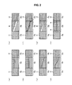
- FIGS. 2A to 2H are drawings illustrating examples of amounts of application of ink in non-head-facing areas in the printing method according to the embodiment of the present invention.
- FIGS. 3A and 3C are drawings schematically illustrating some processes of a printing method according to an embodiment of the present invention.
- FIG. 4 is a drawing for explaining an example of the printing method according to the embodiment of the present invention.
- FIG. 5 is a functional block diagram illustrating a schematic configuration of a printing apparatus according to the embodiment of the present invention.
- FIG. 5 is a functional block diagram illustrating a schematic configuration of a printing apparatus 100 according to an embodiment of the present invention.
- the printing apparatus 100 includes a printhead 110 , a medium angle adjusting unit (head-facing area changing means) 120 , a main control unit 130 , and a data input unit 180 .
- the main control unit 130 includes a discharge control unit (scanning control means) 131 , a scanning control unit (scanning control means) 132 , a medium angle control unit (head-facing area changing means) 133 , a print data memory 134 , and a printing medium data memory 135 .
- the printhead 110 is a printhead for ink jet printing, and is configured to be capable of scanning linearly in predetermined directions.
- a discharging direction of ink 80 from the printhead 110 is set to be perpendicular to the direction of scanning of the printhead 110 . Therefore, the ink 80 discharged from the printhead 110 to a surface facing straight toward the printhead 110 lands perpendicularly at the corresponding surface.
- the term a certain surface “faces the printhead straight in front thereof” indicates that a normal direction of the corresponding surface matches the discharging direction of the ink from the printhead.
- the ink 80 discharged from the printhead 110 which may be used as needed includes ink for ink jet printing.
- the medium angle adjusting unit 120 is, for example, configured to hold the printing medium, which is an object of printing, by a physical or electromagnetic mechanism (for example, a gripping mechanism, a magnet, and the like), and adjust the orientation (angle) of the printing medium by a universal mechanism such as an actuator (for example, rotate the printing medium).
- the medium angle adjusting unit 120 is configured to change an area (head-facing area) of the printing medium, which faces straight toward the front of the printhead 110 by adjusting the orientation of the printing medium.
- the medium angle adjusting unit 120 only has to be capable of adjusting the relative positional relationship between the printhead 110 and the printing medium and, for example, a configuration in which the area facing the printhead 110 straight in front (a head-facing area) thereof on the printing medium is changed by adjusting the position of the printhead 110 is also applicable.
- the main control unit 130 may be implemented as hardware by a logical circuit formed on an integrated circuit (IC chip), or may be implemented as software by using a CPU (Central Processing Unit).
- the main control unit 130 is also provided with memory means as needed for memorizing data.
- the discharge control unit 131 controls the discharging amount of the ink 80 from the printhead 110 .
- the scanning control unit 132 controls scanning operation of the printhead 110 .
- the printing apparatus 100 executes a scanning process for controlling the printhead 110 by the cooperation of the discharge control unit 131 and the scanning control unit 132 , and causing the printhead 110 to discharge the ink 80 onto the printing medium while causing the printhead 110 to scan by a plurality of times.
- the medium angle control unit 133 controls an adjustment of the orientation of the printing medium performed by the medium angle adjusting unit 120 to differentiate the head-facing areas to which the ink 80 is discharged in a state of facing the printhead 110 straight in front from each other in the respective times of scanning processes. For example, the medium angle control unit 133 executes a head-facing area changing process for changing the orientation of the printing medium during two times of continuous scanning processes.
- the print data memory 134 memorizes data indicating image or the like to be printed on the printing medium.
- the printing medium data memory 135 memorizes parameters calculated from data indicating the shape of the printing medium and the shape of the printing medium, which are to be used in the respective scanning processes and the respective head-facing area changing processes. These data is input from the data input unit 180 to the respective memories.
- FIGS. 1A and 1B are drawings schematically illustrating some processes of a printing method according to an embodiment of the present invention. As illustrated in FIGS. 1A and 1B , in this embodiment, a case of printing on a polyhedral printing medium 10 will be described.
- printing is performed on the polyhedron with surfaces thereof faced straight toward the front of the printhead 110 alternately.
- ink coating having a predetermined film thickness T 0 on the surfaces 10 a , 10 b , and 10 c respectively by a scanning process a in which scanning is performed with the surface 10 a faced straight toward the front of the printhead 110 and a scanning process b in which scanning is performed with the surface 10 c faced straight toward the front of the printhead 110 . Accordingly, printing time may be reduced in comparison with a case where printing is performed by facing all of the surfaces straight toward the front of the printhead 110 .
- the printing method of this embodiment needs only to be capable of reducing the printing time by printing at least one of the surfaces without facing at least one of the surfaces straight toward the printhead 110 , and does not necessarily need to print with the surfaces faced straight toward the front of the printhead 110 alternately.
- a surface of the printing medium 10 having a larger surface area is preferably selected as the surface of the printing medium 10 to be printed in a state of being faced straight toward the printhead 110 .
- the printing medium 10 is a polygonal column having a bottom surface as illustrated in FIG. 1A and FIG. 1B
- the printhead 110 will be described in a case where the scanning direction is a depth direction of the paper plane and a horizontal direction of the paper plane in the drawings of FIGS. 1A and 1B .
- FIG. 1A is a drawing schematically illustrating a scanning process a.
- the discharge control unit 131 and the scanning control unit 132 control the printhead 110 to discharge the ink 80 toward the surface 10 a from the direction A perpendicular to the surface 10 a and discharge the ink 80 toward the surface 10 b from a direction B, thereby forming the ink coatings 11 on the surface 10 a and the surface 10 b.
- the scanning control unit 132 may determine a scanning range on the basis of data which indicates the shape of the printing medium 10 memorized in the printing medium data memory 135 . Also, the discharge control unit 131 adjusts the discharging amount of the ink 80 on the basis of data indicating the shape of the printing medium 10 memorized in the printing medium data memory 135 in addition to data indicating the image or the like to be printed memorized in the print data memory 134 as described later.
- the direction B is parallel to the direction A, and intersects the normal direction C of the surface 10 b at an angle of ⁇ 1 .
- the surface 10 a is a head-facing area to which the ink 80 is discharged in a state of facing straight toward the printhead 110 and the surface 10 b is a non-head-facing area to which the ink 80 is discharged without facing straight toward the printhead 110 .
- FIG. 1B is a drawing schematically illustrating the scanning process b.
- the discharge control unit 131 and the scanning control unit 132 control the printhead 110 to discharge the ink 80 toward the surface 10 c from a direction F perpendicular to the surface 10 c and discharge the ink 80 toward the surface 10 b from a direction E, thereby forming the ink coatings 12 on the surface 10 c and the surface 10 b.
- the direction E is parallel to the direction F, and intersects the normal direction D of the surface 10 b at an angle of ⁇ 2 .
- the surface 10 c is a head-facing area to which the ink 80 is discharged in a state of facing straight toward the printhead 110 and the surface 10 b is a non-head-facing area to which the ink 80 is discharged without facing straight toward the printhead 110 .
- the head-facing areas on the printing medium 10 in the scanning process a and the scanning process b are different from each other.
- the head-facing areas are differentiated from each other in the respective times of scanning processes.
- This may be achieved by the medium angle control unit 133 by controlling the medium angle adjusting unit 120 on the basis of the data indicating the shape of the printing medium 10 memorized in the printing medium data memory 135 and causing the printing medium 10 to rotate during the consecutive two times of scanning processes (head-facing area changing process).
- the medium angle control unit 133 may control the medium angle adjusting unit 120 to rotate the printing medium 10 counterclockwise by 90° in FIG. 1A and FIG. 1B .
- the ink 80 is discharged also in the scanning process b to the surface 10 b as the non-head-facing area to which the ink 80 is discharged in the scanning process a as the non-head-facing area.
- the ink 80 is discharged to a non-head-facing area to which the ink 80 is discharged without facing the non-head-facing area straight toward the printhead 110 in any of the scanning processes without facing straight toward the printhead 110 also in other one or more times of scanning processes.
- the ink is discharged in two or more scanning processes for an area which corresponds to the non-head-facing area (hereinafter, referred also simply to as non-head-facing area) in any of the scanning processes.
- the ink coating having the predetermined film thickness T 0 is formed successfully in the non-head-facing area.
- the total film thickness of the ink coatings 11 and 12 formed on the surface 10 b may be equalized to the film thickness of the ink coating 11 formed on the surface 10 a and the film thickness of the ink coating 12 formed on the surface 10 c . The reason is as follows.
- the film thickness of the ink coating formed in the non-head-facing area is smaller than the film thickness of the ink coating formed in the head-facing area. It is because the non-head-facing area is inclined with respect to the discharging direction of the ink 80 , the surface area in which the ink 80 lands becomes wider than the head-facing area.
- the ink coating having the predetermined film thickness T 0 may be formed successfully in the same manner as the head-facing area while avoiding the film thickness of the ink coating formed in the corresponding area from becoming thinner.
- the discharge control unit 131 preferably adjusts the amount of the ink 80 discharged in the non-head-facing area in at least one of the scanning processes so that the total film thickness of the ink coating formed in the non-head-facing area becomes equal to the film thickness of the ink coating to be formed on the head-facing area.
- the discharge control unit 131 sets the discharging amount of the ink 80 as described below.
- the total film thickness of the ink coating to be formed in the non-head-facing area may be equalized to the predetermined film thickness T 0 , which is the same as the film thickness of the ink coating to be formed on the head-facing area.
- the discharge control unit 131 does not have to perform adjustment of the ink discharging amount necessarily in all of the scanning processes from among the above-described n times of the scanning processes. In other words, adjustment does not have to be performed (the discharging amount with respect to the non-head-facing area may be the same discharging amount with respect to the head-facing area) in some of the scanning processes. In such a case, the coefficient of adjustment k in the corresponding scanning process may be set to “1”.
- the discharge control unit 131 may calculate the above-described ⁇ i from data indicating the shape of the printing medium 10 acquired from the printing medium data memory 135 , or may acquire ⁇ i directly from the printing medium data memory 135 .
- the amount of the ink 80 to be discharged to the non-head-facing area may be set to be smaller than the amount of the ink 80 to be discharged to the head-facing area in at least one of the above-described scanning process.
- the ink coating having the predetermined film thickness T 0 may be formed in the non-head-facing area without increasing the ink 80 to be discharged from the printhead 110 .
- scanning with the printhead 110 is preferably performed so as to transverse the head-facing area and the non-head-facing area as the scanning process a and the scanning process b in at least one of the scanning processes. Accordingly, printing time may be reduced since the head-facing area and the non-head-facing area may be printed in one scanning processes.
- FIGS. 2A to 2H are drawings illustrating examples of amounts of application of ink in non-head-facing areas.
- adjustment of the discharging amount of the ink 80 to the non-head-facing area may be performed in various modes.
- the adjustment of the discharging amount of the ink 80 to the non-head-facing area is not limited to the modes exemplified in FIG. 2A to FIG. 2H as long as the above-described conditions are satisfied.
- the same adjustment may be performed for all of the non-head-facing areas and adjustments in modes different from each other may be performed therefor.
- the same amount of the ink 80 is discharged to the surface 10 a (head-facing area) and the surface 10 b (non-head-facing area, first area) in the scanning process a (type 1 scanning process), and the ink 80 of a smaller amount than to the surface 10 c (head-facing area) is discharged to the surface 10 b (non-head-facing area) so that the total film thickness of the ink coatings 11 and 12 formed on the surface 10 b becomes the predetermined film thickness T 0 in the scanning process b (type 2 scanning process).
- the ink coating 11 to be formed on the surface 10 b is thinner than the ink coating 11 to be formed on the surface 10 a . It is because the surface area to be printed by the ink 80 droplets is larger than the surface 10 a to be in a state of facing straight toward the printhead 110 because the surface 10 b is printed in a state not to face straight toward the printhead 110 . Therefore, by forming additionally the ink coating 12 on the surface 10 b in the scanning process b, the total film thickness of the ink coatings 11 and 12 to be formed on the surface 10 b may be set to the predetermined film thickness T 0 .
- the ink 80 to be discharged from the front in the scanning process a occupies a larger ratio in the ink 80 discharged to the surface 10 b when the printing medium 10 is observed mainly with the surface 10 a oriented to the front, the printed image quality of the surface 10 b when observing from the front may be improved.
- the amount of the ink 80 to be discharged to the surface 10 b (second area) is adjusted in the scanning process a and the scanning process b (type 3 scanning process) so that the film thicknesses of the ink coatings 11 and 12 to be formed on the surface 10 b in the scanning process a and the scanning process b (type 3 scanning process) are the same, and the total film thickness of the ink coatings 11 and 12 to be formed on the surface 10 b becomes the predetermined film thickness T 0 .
- the printing medium 10 is observed from various directions (for example, directions facing straight toward the surface 10 a and the surface 10 c ), since the film thicknesses of the ink coating to be formed on the surface 10 b in the respective scanning processes are uniform. Therefore, such an event that the printed image quality of the surface 10 b is deteriorated when observing from a certain direction is suppressed.
- the discharge control unit 131 controls the amount of ink 80 to be discharged to a boundary between the surface 10 a (head-facing area) and the surface 10 b (third area) to be the same amount as the amount of the ink 80 to be discharged to the surface 10 a , and changes the discharging amount of the ink 80 continuously from the boundary to the surface 10 b . More specifically, the discharge control unit 131 changes the discharging amount of the ink 80 continuously from the above-described boundary to the surface 10 b so as to decrease as it goes farther from the boundary.
- the discharge control unit 131 controls the amount of ink 80 to be discharged to a boundary between the surface 10 c (head-facing area) and the surface 10 b (third area) to be the same amount as the amount of the ink 80 to be discharged to the surface 10 c , and changes the discharging amount of the ink 80 continuously from the boundary to the surface 10 b . More specifically, the discharge control unit 131 changes the discharging amount of the ink 80 continuously from the above-described boundary to the surface 10 b so as to decrease as it goes farther from the boundary. Accordingly, in the same manner, continuity of printing between the surface 10 c and the surface 10 b is secured, so that the printed image quality is improved.
- the discharging amount of the ink 80 may be adjusted so that portions to which the same amount of the ink 80 as the head-facing area (surfaces 10 a and 10 c ) is discharged do not overlap with each other and an ink coating having the predetermined total film thickness T 0 is formed on the surface 10 b .
- the head-facing area is closer to the printhead than the non-head-facing area. Therefore, by setting the ink discharging amount on the boundary with respect to the head-facing area to be large in the surface 10 b as described above, a large amount of the ink 80 is discharged in a state of being closer to the printhead 110 , and hence the image quality in the surface 10 b is improved.
- a portion where the ink discharging amount is to be changed may extend over the entire part of the surface 10 b as illustrated in FIG. 2C , or may be limited to part of the surface 10 b depending on a pattern or the like to be printed as illustrated in FIG. 2D . Also, the ink discharging amount changing modes in the respective scanning processes are preferably changed so as to correspond to each other.
- the discharge control unit 131 controls the amount of ink 80 to be discharged to a boundary between the surface 10 a (head-facing area) and the surface 10 b (fourth area) to be the same amount as the amount of the ink 80 to be discharged to the surface 10 a , and changes the discharging amount of the ink 80 unevenly from the boundary to the surface 10 b . More specifically, the discharge control unit 131 changes the discharging amount of the ink 80 from the above-described boundary to the surface 10 b so as to vary within a range indicated by reference sign M in FIG. 2E and FIG. 2G (varies for example as illustrated in FIG. 2F ).
- the discharge control unit 131 controls the amount of ink 80 to be discharged to a boundary between the surface 10 c (head-facing area) and the surface 10 b (fourth area) to be the same amount as the amount of the ink 80 to be discharged to the surface 10 c , and changes the discharging amount of the ink 80 unevenly so as to correspond to the scanning process a from the boundary to the surface 10 b . Accordingly, in the same manner, continuity of printing between the surface 10 c and the surface 10 b is secured, so that the printed image quality is improved.
- a method of changing the ink discharging amount unevenly for example, a method of setting a displacement width such as the range indicated by the reference sign M in FIG. 2E and FIG. 2G , and adding a noise so as to cause the fluctuation within the displacement width may be used.
- the discharging amount of the ink 80 may be adjusted so that portions to which the same amount of the ink 80 as the head-facing area (surfaces 10 a and 10 c ) is discharged do not overlap with each other and an ink coating having the predetermined total film thickness T 0 is formed on the surface 10 b in these examples as well. Also, in this example, in the same manner as the examples illustrated in FIG. 2C and FIG. 2D , by increasing the ink discharging amount at the boundary with respect to the head-facing area in the surface 10 b , the image quality of the surface 10 b may be improved. Also, in the same manner as the examples illustrated in FIG. 2C and FIG.
- a portion where the ink discharging amount is to be changed may extend over the entire part of the surface 10 b as illustrated in FIG. 2C , or may be limited to part of the surface 10 b depending on a pattern or the like to be printed as illustrated in FIG. 2D .
- positions where the discharging amount of the ink 80 is changed may be varied.
- dither methods such as ordered dither or random dither, error diffusion, noise addition or the like may be applied.
- FIGS. 3A to 3C are drawings schematically illustrating some processes of a printing method according to another embodiment of the present invention. As illustrated in FIGS. 3A to 3C , a case of printing on a printing medium 20 , which is a solid bounded by curved surface, will be described in this embodiment.
- a curved surface of the solid bounded by curved surface is divided and the respective divided surfaces are printed from two or more directions.
- a side surface of the printing medium 20 is divided into areas 20 a to 20 d , and an ink coating having the predetermined film thickness T 0 is formed in each of the areas by a scanning process a in which a boundary between the area 20 a and the area 20 b faces straight toward the printhead 110 and printing is performed in the area 20 a and the area 20 b as the non-head-facing areas, a scanning process b in which a boundary between the area 20 b and the area 20 c faces straight toward the printhead 110 and printing is performed in the area 20 b and the area 20 c as the non-head-facing areas, and a scanning process c in which a boundary between the area 20 c and the area 20 d faces straight toward the printhead 110 and printing is performed in the area 20 c and the area 20 d as the non-head-facing areas
- the printing medium 20 is a column having a bottom surface as illustrated in FIG. 3A to FIG. 3C
- the printhead 110 in a case where the scanning direction is a depth direction of the paper plane and a horizontal direction of the paper plane in the drawings of FIG. 3A to FIG. 3C will be described.
- the side surface of the printing medium 20 is divided into eight areas including the areas 20 a to 20 d by every center angle 45°.
- FIG. 3A to FIG. 3C are drawings schematically illustrating the scanning process a to the scanning process c.
- the discharge control unit 131 and the scanning control unit 132 control the printhead 110 to discharge the ink 80 to adjacent areas in a state in which a boundary between the adjacent areas face straight toward the printhead 110 , and forms the ink coatings 21 to 23 .
- the medium angle control unit 133 controls the medium angle adjusting unit 120 to rotate the printing medium 20 counterclockwise by 45° in FIG. 3A to FIG. 3C .
- the ink is discharged to all of the areas on the printing medium 20 including the areas 20 a to 20 d during the two times of scanning processes, so that the ink coating whose total film thickness is the predetermined film thickness T 0 can be formed.
- the discharging amount of the ink 80 with respect to the non-head-facing area is adjusted so that the total film thickness becomes the predetermined film thickness T 0 as described above. More specifically, the discharge control unit 131 adjusts the discharging amount of the ink 80 as described below, for example, with respect to the point where a line H is positioned in the area 20 b in FIG. 3A .
- N rab N 0 cos ⁇ (6) (where N 0 is a film thickness of the ink coating 21 formed on a boundary (head-facing area) between the area 20 a and the area 20 b , and 8 is an angle between the discharging direction G of the ink 80 and the line H.
- N 0 is equal to the predetermined film thickness T 0 .
- the relationship between the coefficient of adjustment k and the ink discharging amount D i is as shown in Expression (2).
- printing of the respective divided surfaces of the column may be performed from the direction n (n>2).
- n an angle between the discharging direction of the ink 80 in the i-th scanning process and the normal direction of the printing medium 20 at the corresponding one point is expressed by ⁇ i
- adjustment of the discharging amount of the ink 80 to the non-head-facing area may be performed in various modes.
- FIG. 4 is a drawing for explaining a case where printing on a printing medium 30 having a quadrangular prism shape rounded at corners by using a printing method according to an embodiment of the present invention.
- the printing method of this embodiment includes a scanning process a in which the ink 80 is discharged to an area 30 a from a direction O, a scanning process b in which the ink 80 is discharged to an area 30 b from a direction P, and a scanning process c in which the ink 80 is discharged to an area 30 c from a direction Q.
- printing may be performed with end surfaces at corners of the quadrangular prism faced straight toward the printhead 110 .
- the printing method of this embodiment is preferable when the end surfaces of the corners are too long to print from two directions (directions O and Q), and the image quality may be improved by preventing occurrence of landing failure of the ink droplets.
- the smaller the ink droplet size, the shorter the distance in which the landing failure occurs. Therefore, the printing method of this embodiment may be applied in accordance with the performance of the printhead 110 , the scanning speed, and characteristics (for example, mass) or the like of the ink 80 .
- the end surface portion may be divided into a plurality of areas for printing.
- the printing method includes: a plurality of times of a scanning process including scanning with a printhead 110 for ink jet printing and discharging the ink 80 to a printing medium (for example, the printing medium 10 , the printing medium 20 , and the like) from the printhead 110 , and includes: differentiating the head-facing areas to which the ink 80 is discharged in a state of facing straight toward the printhead 110 (for example, the surface 10 a in FIG. 1A , the surface 10 c in FIG. 1B , the boundary between the area 20 a and the area 20 b in FIG. 3A , the boundary between the area 20 b and the area 20 c in FIG.
- the total film thickness of the coating formed in the non-head-facing area (for example, the ink coatings 11 , 12 , and 21 to 23 , and the like) becomes a predetermined film thickness T 0 .
- the ink 80 is discharged to the area which corresponds to the non-head-facing area in any of the scanning processes to each of areas in two or more times of the scanning processes. Therefore, the film thickness of the ink coating to be formed in the non-head-facing area is prevented from becoming thinner than the head-facing area.
- the ink coating having a predetermined film thickness T 0 is formed on a surface of a printing medium having a three-dimensional structure in shorter time.
- the amount of the ink 80 to be discharged in the non-head-facing area is adjusted so that the total film thickness of the coating of the ink 80 formed in the non-head-facing area becomes equal to the film thickness of the coating of the ink 80 formed on the head-facing area in the above-described at least one of the scanning processes.
- the ink coating having the same film thickness as the head-facing area may be formed also in the non-head-facing area.
- the amount of the ink 80 to be discharged in the non-head-facing area is adjusted to be smaller than the amount of ink 80 to be discharged to the head-facing area in at least one of the scanning processes.
- the ink coating having the predetermined film thickness T 0 may be successfully formed in the non-head-facing area.
- ⁇ i is an angle smaller than 90°, and indicates an angle formed between a discharging direction of the ink 80 in the above-described i-th scanning process among the n times of the scanning process and a normal direction of the printing medium at that time point.
- the discharging amount of the ink 80 with respect to one point of the non-head-facing area may be preferably adjusted so that the film thickness of the ink coating to be formed on one point of the non-head-facing area becomes the same as the film thickness of the ink coating to be formed in the head-facing area, the ink coating having the predetermined film thickness T 0 may be successfully formed on the surface of the printing medium.
- scanning with the printhead 110 is performed so as to transverse the head-facing area and the non-head-facing area in the at least one of the scanning processes.
- both of the head-facing area and the non-head-facing area can be scanned in one time of the scanning process without performing the positioning action between the printhead 110 and the printing medium. Accordingly, the number of times of the positioning operations may be reduced, and hence the printing time may be reduced.
- the positioning action between the printhead 110 and the printing medium 20 is very much increased and the printing time is increased.
- the side surface is divided into a plurality of areas in the circumferential direction, and that the respective divided surfaces are printed in two or more scanning processes, and hence the positioning action between the printhead 110 and the printing medium 20 is reduced, and the printing time may be reduced.
- the film thickness of the ink coating to be formed in the first area in the type 1 scanning process is thinner than the film thickness of the ink coating formed in the head-facing area.
- the ink 80 is further applied to the first area in the type 2 scanning process, the ink coating having the predetermined film thickness T 0 may be formed in the first area.
- the ink 80 to be discharged in the same scanning process as the head-facing area occupies a larger ratio in the ink 80 discharged to the first area in the above-described configuration when the printing medium is observed mainly with head-facing area in the type 1 scanning process oriented to the front, the printed image quality in the first area when observing from the front may be improved.
- a configuration in which the ink 80 is discharged to a second area, which is part of the printing medium, without facing the second area straight toward the printhead 110 , in two or more times of the scanning processes, the two or more times of the scanning process includes two or more times of type 3 scanning process, and the ink 80 is discharged so that ink coatings having the same film thickness are formed in the second area in the respective times of the type 3 scanning process is also applicable.
- the ink coating having the predetermined film thickness T 0 may be successfully formed on the surface of the printing medium.
- the ink 80 is discharged to a third area, which is part of the printing medium, without facing the third area straight toward the printhead 110 in two or more times of the scanning processes, the two or more times of the scanning process includes two or more times of type 4 scanning process, scanning with the printhead 110 is performed so as to transverse the third area and the head-facing area in the respective type 4 scanning processes, the same amount of ink 80 as the amount to be discharged to the head-facing area is discharged to a boundary between the third area and the head-facing area, and the amount of ink 80 to be discharged is continuously changed from the boundary to the third area.
- the total film thickness of the ink coating to be formed in the third area may exceed the predetermined film thickness T 0 .
- the head-facing areas in the respective type 4 scanning processes are different from each other, boundaries between the head-facing area and the third area are also different.
- the portions to which the same amount of ink 80 as the head-facing area is discharged do not overlap in the respective type 4 scanning processes, and the discharging amount of the ink 80 may be adjusted so that the ink coating having the predetermined total film thickness T 0 is formed in the third area.
- the head-facing area is closer to the printhead 110 than the non-head-facing area. Therefore, as described above, by setting the ink discharging amount on the boundary with respect to the head-facing area to be large in the third area, a large amount of the ink 80 is discharged in a state of being closer to the printhead 110 , and hence the image quality in the third area is improved.
- a portion where the ink discharging amount is to be changed may extend over the entire part of the third area, or may be limited to part of the third area depending on a pattern or the like to be printed.
- the ink 80 is discharged to a fourth area, which is part of the printing medium, without facing the fourth area straight toward the printhead 110 in two or more times of the scanning processes, the two or more times of the scanning process includes two or more times of type 5 scanning process, scanning with the printhead 110 is performed so as to transverse the fourth area and the head-facing area in the respective type 5 scanning processes, the same amount of ink 80 as the amount to be discharged to the head-facing area is discharged to a boundary between the fourth area and the head-facing area, and the amount of ink 80 to be discharged is unevenly changed from the boundary to the fourth area.
- the total film thickness of the ink coating to be formed in the fourth area may exceed the predetermined film thickness T 0 .
- the head-facing areas in the respective type 5 scanning processes are different from each other, boundaries between the head-facing area and the fourth area are also different.
- the portions to which the same amount of ink 80 as the head-facing area is discharged do not overlap in the respective type 5 scanning processes, and the discharging amount of the ink 80 may be adjusted so that the ink coating having the predetermined total film thickness T 0 is formed in the fourth area.
- the head-facing area is closer to the printhead 110 than the non-head-facing area. Therefore, as described above, by setting the ink discharging amount on the boundary with respect to the head-facing area to be large in the fourth area, a large amount of the ink 80 is discharged in a state of being closer to the printhead 110 , and hence the image quality in the fourth area is improved.
- positions where the amount of the ink 80 is changed may be varied.
- a printing apparatus 100 includes: a printhead 110 for ink jet printing; discharge control unit 131 and the scanning control unit 132 configured to control the printhead 110 to perform a scanning process in which ink 80 is discharged from the printhead 110 to the printing medium while scanning with the printhead 110 by a plurality of times; and the medium angle adjusting unit 120 and the medium angle control unit 133 configured to differentiate head-facing areas to which the ink 80 is discharged in a state of facing straight toward the printhead 110 from each other in the respective scanning processes, and the discharge control unit 131 and the scanning control unit 132 control the printhead 110 so that the ink 80 is discharged to a non-head-facing area, to which the ink 80 is discharged, without facing the non-head-facing area straight toward the printhead 110 also in other one or more scanning processes, and the amount of the ink 80 to be discharged in the non-head-facing area in at least one of the scanning processes is adjusted so that the total film thickness of the coating film of the ink 80
- the present invention is applicable to a field of printing process for various articles, and a field of manufacture of the printing apparatus.
Abstract
Description
- PTL 1: JP-A-9-193368 (published Jul. 29, 1997)
- PTL 2: JP-A-2006-335019 (published Dec. 14, 2006)
D i =k i ×D 0 (2)
(where D0 denotes the above-described amount of the ink to be discharged to one point in the above-described head-facing area in the respective scanning processes) by using a coefficient of adjustment ki set so as to satisfy the following expression (1)
D i =k i ×D 0 (2)
(where D0 denotes the amount of the
D 2=(1−cos θ1)/cos θ2 ×D 0 (3)
by assigning n=2, ki=1 to above-described Expression (1) and Expression (2), for example.
D 1 =D 0/2 cos θ1 (4)
D 2 =D 0/2 cos θ2 (5).
N rab =N 0 cos θ (6)
(where N0 is a film thickness of the
N rbc =N 0 cos(45°−θ) (7)
k 1 N rab +k 2 N rbc =N 0 (8)
in other words,
k 1 N 0 cos(45°−θ)+k 2 N 0 cos θ=N 0 (9).
k 1 N 0 cos θ1 +k 2 N 0 cos θ2 + . . . +k n N 0 cos θn =N 0 (10).
D i =k i ×D 0 (2)
(where D0 denotes the amount of the
Claims (11)
D i =k i ×D 0 (2)
D i =k i ×D 0 (2)
Applications Claiming Priority (3)
| Application Number | Priority Date | Filing Date | Title |
|---|---|---|---|
| JP2011-157107 | 2011-07-15 | ||
| JP2011157107A JP5730698B2 (en) | 2011-07-15 | 2011-07-15 | Printing method and printing apparatus |
| PCT/JP2012/067392 WO2013011851A1 (en) | 2011-07-15 | 2012-07-06 | Printing method and printing device |
Publications (2)
| Publication Number | Publication Date |
|---|---|
| US20140132670A1 US20140132670A1 (en) | 2014-05-15 |
| US8926063B2 true US8926063B2 (en) | 2015-01-06 |
Family
ID=47558029
Family Applications (1)
| Application Number | Title | Priority Date | Filing Date |
|---|---|---|---|
| US14/125,088 Active US8926063B2 (en) | 2011-07-15 | 2012-07-06 | Printing method and printing apparatus |
Country Status (5)
| Country | Link |
|---|---|
| US (1) | US8926063B2 (en) |
| JP (1) | JP5730698B2 (en) |
| KR (1) | KR101552927B1 (en) |
| CN (1) | CN103648783B (en) |
| WO (1) | WO2013011851A1 (en) |
Families Citing this family (14)
| Publication number | Priority date | Publication date | Assignee | Title |
|---|---|---|---|---|
| WO2014163196A1 (en) * | 2013-04-04 | 2014-10-09 | コニカミノルタ株式会社 | Inkjet printing method |
| JP6260353B2 (en) * | 2013-04-23 | 2018-01-17 | 株式会社リコー | Information processing apparatus, information processing method, and control program |
| JP6278704B2 (en) * | 2013-12-27 | 2018-02-14 | 株式会社ミマキエンジニアリング | Manufacturing method of printed matter |
| JP6317936B2 (en) * | 2014-02-05 | 2018-04-25 | 株式会社ミマキエンジニアリング | Method for producing printed matter and printing system |
| CN103862866A (en) * | 2014-04-05 | 2014-06-18 | 晏石英 | Printing method and printer |
| JP6452153B2 (en) * | 2015-03-25 | 2019-01-16 | 株式会社ミマキエンジニアリング | Method for decorating rod-shaped members |
| EP3957487B1 (en) | 2015-05-27 | 2023-12-20 | NIKE Innovate C.V. | Color density based thickness compensation printing |
| KR102189939B1 (en) * | 2016-05-31 | 2020-12-11 | 나이키 이노베이트 씨.브이. | Gradient printing of three-dimensional structural components |
| JP7000092B2 (en) * | 2017-09-25 | 2022-01-19 | 武藤工業株式会社 | Cylindrical printing method and equipment |
| FR3087704B1 (en) * | 2018-10-26 | 2021-04-30 | Psa Automobiles Sa | SURFACE PRINTING WITH OVERLAPPING STRIPS |
| JP7285827B2 (en) | 2019-06-26 | 2023-06-02 | アーベーベー・シュバイツ・アーゲー | Coating machine and coating method |
| CN114340802B (en) * | 2019-08-30 | 2023-09-29 | 京瓷株式会社 | Coating device, coating film and coating method |
| WO2021245659A1 (en) * | 2020-06-01 | 2021-12-09 | Veev Group, Inc. | System, method and computer program product for side printing on solid surfaces |
| CN112571988A (en) * | 2020-12-02 | 2021-03-30 | 深圳汉弘数字印刷集团股份有限公司 | Printing method, printing device, ink-jet printer and storage medium |
Citations (9)
| Publication number | Priority date | Publication date | Assignee | Title |
|---|---|---|---|---|
| JPH09193368A (en) | 1996-01-12 | 1997-07-29 | Canon Inc | Ink jet printer and ink jet printing method |
| JPH11276978A (en) | 1998-03-31 | 1999-10-12 | Hitachi Zosen Corp | Formulation of coating film thickness in coating robot |
| JP2001260329A (en) | 2000-03-22 | 2001-09-25 | Minolta Co Ltd | Apparatus and method for printing three-dimensional object |
| JP2003320299A (en) | 2002-04-30 | 2003-11-11 | Fujimori Gijutsu Kenkyusho:Kk | Thin film coating method and control unit thereof |
| JP2005254817A (en) | 2005-04-20 | 2005-09-22 | Seiko Epson Corp | Printer, printing method, and recording medium |
| JP2006335019A (en) | 2005-06-06 | 2006-12-14 | Mimaki Engineering Co Ltd | Inkjet printer for solid medium printing, and printing method using the same |
| JP2007106049A (en) | 2005-10-14 | 2007-04-26 | Honda Motor Co Ltd | Curved surface printing method |
| JP2009012430A (en) | 2007-07-09 | 2009-01-22 | Inax Corp | Inkjet printing apparatus and inkjet printing method |
| US20090169719A1 (en) * | 2007-12-31 | 2009-07-02 | Exatec Llc | Method for printing high quality images on curved substrates |
Family Cites Families (3)
| Publication number | Priority date | Publication date | Assignee | Title |
|---|---|---|---|---|
| US6460958B2 (en) * | 2000-02-29 | 2002-10-08 | Minolta Co., Ltd. | Three-dimensional object printing apparatus and method |
| JP2002264309A (en) * | 2001-03-14 | 2002-09-18 | Canon Inc | Recording apparatus |
| TW200638083A (en) * | 2005-04-18 | 2006-11-01 | Shibaura Mechatronics Corp | The coating apparatus and method thereof |
-
2011
- 2011-07-15 JP JP2011157107A patent/JP5730698B2/en active Active
-
2012
- 2012-07-06 WO PCT/JP2012/067392 patent/WO2013011851A1/en active Application Filing
- 2012-07-06 KR KR1020137032790A patent/KR101552927B1/en active IP Right Grant
- 2012-07-06 US US14/125,088 patent/US8926063B2/en active Active
- 2012-07-06 CN CN201280035220.7A patent/CN103648783B/en active Active
Patent Citations (9)
| Publication number | Priority date | Publication date | Assignee | Title |
|---|---|---|---|---|
| JPH09193368A (en) | 1996-01-12 | 1997-07-29 | Canon Inc | Ink jet printer and ink jet printing method |
| JPH11276978A (en) | 1998-03-31 | 1999-10-12 | Hitachi Zosen Corp | Formulation of coating film thickness in coating robot |
| JP2001260329A (en) | 2000-03-22 | 2001-09-25 | Minolta Co Ltd | Apparatus and method for printing three-dimensional object |
| JP2003320299A (en) | 2002-04-30 | 2003-11-11 | Fujimori Gijutsu Kenkyusho:Kk | Thin film coating method and control unit thereof |
| JP2005254817A (en) | 2005-04-20 | 2005-09-22 | Seiko Epson Corp | Printer, printing method, and recording medium |
| JP2006335019A (en) | 2005-06-06 | 2006-12-14 | Mimaki Engineering Co Ltd | Inkjet printer for solid medium printing, and printing method using the same |
| JP2007106049A (en) | 2005-10-14 | 2007-04-26 | Honda Motor Co Ltd | Curved surface printing method |
| JP2009012430A (en) | 2007-07-09 | 2009-01-22 | Inax Corp | Inkjet printing apparatus and inkjet printing method |
| US20090169719A1 (en) * | 2007-12-31 | 2009-07-02 | Exatec Llc | Method for printing high quality images on curved substrates |
Non-Patent Citations (1)
| Title |
|---|
| International Search Report in International Application No. PCT/JP2012/067392 dated Oct. 9, 2012. |
Also Published As
| Publication number | Publication date |
|---|---|
| JP5730698B2 (en) | 2015-06-10 |
| CN103648783B (en) | 2016-03-02 |
| KR20140021019A (en) | 2014-02-19 |
| JP2013022768A (en) | 2013-02-04 |
| US20140132670A1 (en) | 2014-05-15 |
| CN103648783A (en) | 2014-03-19 |
| WO2013011851A1 (en) | 2013-01-24 |
| KR101552927B1 (en) | 2015-09-14 |
Similar Documents
| Publication | Publication Date | Title |
|---|---|---|
| US8926063B2 (en) | Printing method and printing apparatus | |
| WO2016152208A1 (en) | Ink jet recording apparatus and ink jet recording method | |
| EP2783865B1 (en) | Liquid jetting apparatus and recording method using the same | |
| US10828890B2 (en) | Printing apparatus and printhead adjustment method | |
| US9463619B2 (en) | Inkjet printer and image recording method | |
| US20060114287A1 (en) | Real-time interlace adjustment based on predicted image quality | |
| US9283752B2 (en) | Method for printing contiguous swaths | |
| JP6173121B2 (en) | Recording apparatus and recording method | |
| WO2016186014A1 (en) | Droplet discharge head, droplet discharge head unit, image formation device, and method for mounting droplet discharge head | |
| JP2010094841A (en) | Liquid ejecting apparatus | |
| WO2012115107A1 (en) | Offset printer | |
| JPH0939220A (en) | Image recorder | |
| US20200198363A1 (en) | Image forming apparatus, halftone processing method, and halftone processing program | |
| KR101361456B1 (en) | Vector printing method of electronic print system using cad drawings | |
| JP2013067092A (en) | Printer and printing method | |
| US9895918B2 (en) | Image forming apparatus, image forming system, and method for forming test patterns | |
| JP6610179B2 (en) | Droplet discharge device | |
| JP7024438B2 (en) | Liquid discharge device, liquid discharge method, liquid discharge program and image forming device | |
| JP6690370B2 (en) | Printer | |
| JP2014171956A (en) | Method for forming coating film and coating device | |
| JP2003305830A (en) | Recording apparatus and recording method | |
| JP2019119156A (en) | Liquid discharge device, liquid discharge method, liquid discharge program and image formation apparatus | |
| JP2006123448A (en) | Printer | |
| CN117429177A (en) | Recording apparatus and recording method | |
| JP2009234092A (en) | Ink and dampening water feed controller |
Legal Events
| Date | Code | Title | Description |
|---|---|---|---|
| AS | Assignment |
Owner name: MIMAKI ENGINEERING CO., LTD., JAPAN Free format text: ASSIGNMENT OF ASSIGNORS INTEREST;ASSIGNORS:IKEDA, AKIRA;OHNISHI, MASARU;REEL/FRAME:031746/0532 Effective date: 20131202 |
|
| STCF | Information on status: patent grant |
Free format text: PATENTED CASE |
|
| MAFP | Maintenance fee payment |
Free format text: PAYMENT OF MAINTENANCE FEE, 4TH YEAR, LARGE ENTITY (ORIGINAL EVENT CODE: M1551) Year of fee payment: 4 |
|
| MAFP | Maintenance fee payment |
Free format text: PAYMENT OF MAINTENANCE FEE, 8TH YEAR, LARGE ENTITY (ORIGINAL EVENT CODE: M1552); ENTITY STATUS OF PATENT OWNER: LARGE ENTITY Year of fee payment: 8 |