US8926012B2 - Vehicle seats for vehicles - Google Patents
Vehicle seats for vehicles Download PDFInfo
- Publication number
- US8926012B2 US8926012B2 US13/216,537 US201113216537A US8926012B2 US 8926012 B2 US8926012 B2 US 8926012B2 US 201113216537 A US201113216537 A US 201113216537A US 8926012 B2 US8926012 B2 US 8926012B2
- Authority
- US
- United States
- Prior art keywords
- connecting means
- frame
- deformation device
- vehicle seat
- web
- Prior art date
- Legal status (The legal status is an assumption and is not a legal conclusion. Google has not performed a legal analysis and makes no representation as to the accuracy of the status listed.)
- Expired - Fee Related, expires
Links
Images


Classifications
-
- B—PERFORMING OPERATIONS; TRANSPORTING
- B60—VEHICLES IN GENERAL
- B60N—SEATS SPECIALLY ADAPTED FOR VEHICLES; VEHICLE PASSENGER ACCOMMODATION NOT OTHERWISE PROVIDED FOR
- B60N2/00—Seats specially adapted for vehicles; Arrangement or mounting of seats in vehicles
- B60N2/24—Seats specially adapted for vehicles; Arrangement or mounting of seats in vehicles for particular purposes or particular vehicles
- B60N2/42—Seats specially adapted for vehicles; Arrangement or mounting of seats in vehicles for particular purposes or particular vehicles the seat constructed to protect the occupant from the effect of abnormal g-forces, e.g. crash or safety seats
- B60N2/4207—Seats specially adapted for vehicles; Arrangement or mounting of seats in vehicles for particular purposes or particular vehicles the seat constructed to protect the occupant from the effect of abnormal g-forces, e.g. crash or safety seats characterised by the direction of the g-forces
- B60N2/4214—Seats specially adapted for vehicles; Arrangement or mounting of seats in vehicles for particular purposes or particular vehicles the seat constructed to protect the occupant from the effect of abnormal g-forces, e.g. crash or safety seats characterised by the direction of the g-forces longitudinal
- B60N2/4221—Seats specially adapted for vehicles; Arrangement or mounting of seats in vehicles for particular purposes or particular vehicles the seat constructed to protect the occupant from the effect of abnormal g-forces, e.g. crash or safety seats characterised by the direction of the g-forces longitudinal due to impact coming from the front
-
- B—PERFORMING OPERATIONS; TRANSPORTING
- B60—VEHICLES IN GENERAL
- B60N—SEATS SPECIALLY ADAPTED FOR VEHICLES; VEHICLE PASSENGER ACCOMMODATION NOT OTHERWISE PROVIDED FOR
- B60N2/00—Seats specially adapted for vehicles; Arrangement or mounting of seats in vehicles
- B60N2/24—Seats specially adapted for vehicles; Arrangement or mounting of seats in vehicles for particular purposes or particular vehicles
- B60N2/42—Seats specially adapted for vehicles; Arrangement or mounting of seats in vehicles for particular purposes or particular vehicles the seat constructed to protect the occupant from the effect of abnormal g-forces, e.g. crash or safety seats
- B60N2/4207—Seats specially adapted for vehicles; Arrangement or mounting of seats in vehicles for particular purposes or particular vehicles the seat constructed to protect the occupant from the effect of abnormal g-forces, e.g. crash or safety seats characterised by the direction of the g-forces
- B60N2/4214—Seats specially adapted for vehicles; Arrangement or mounting of seats in vehicles for particular purposes or particular vehicles the seat constructed to protect the occupant from the effect of abnormal g-forces, e.g. crash or safety seats characterised by the direction of the g-forces longitudinal
- B60N2/4228—Seats specially adapted for vehicles; Arrangement or mounting of seats in vehicles for particular purposes or particular vehicles the seat constructed to protect the occupant from the effect of abnormal g-forces, e.g. crash or safety seats characterised by the direction of the g-forces longitudinal due to impact coming from the rear
-
- B—PERFORMING OPERATIONS; TRANSPORTING
- B60—VEHICLES IN GENERAL
- B60N—SEATS SPECIALLY ADAPTED FOR VEHICLES; VEHICLE PASSENGER ACCOMMODATION NOT OTHERWISE PROVIDED FOR
- B60N2/00—Seats specially adapted for vehicles; Arrangement or mounting of seats in vehicles
- B60N2/24—Seats specially adapted for vehicles; Arrangement or mounting of seats in vehicles for particular purposes or particular vehicles
- B60N2/42—Seats specially adapted for vehicles; Arrangement or mounting of seats in vehicles for particular purposes or particular vehicles the seat constructed to protect the occupant from the effect of abnormal g-forces, e.g. crash or safety seats
- B60N2/427—Seats or parts thereof displaced during a crash
- B60N2/42709—Seats or parts thereof displaced during a crash involving residual deformation or fracture of the structure
Definitions
- the invention concerns a vehicle seat for trucks, buses, cars, tractors, ships, working machines e.g. construction machinery and forklift trucks, rail vehicles or aircraft or similar.
- the vehicle seat can for example be intended for the driver of such a transport medium or for a passenger in the conventional sense i.e. a person carried by such a transport medium without controlling it.
- Passenger seats are known from high speed trains which have a seating surface, a back rest and a foot to support the seating surface or unit of seating surface and back rest on the floor of the train.
- the seating surface and back rest usually have a relatively hard supporting “core” covered by upholstery.
- the construction here referred to as the core can be designed in principle in widely varying ways, for example having plates, webs or similar.
- the back rest is often designed in relation to the seating surface so that in particular the angle of the back rest to the seating surface can be altered. When the back rest is in the selected position, it is usually relatively rigidly connected with or arranged in relation to the seat.
- the foot is normally formed by one—or two spaced in the transverse seat direction—plate or column-like element(s), which runs or run substantially vertical or angled to the vertical direction to keep the seating surface at a distance from the floor of the train, and on the bottom of which is formed a carrier running in the seat longitudinal direction i.e. in the direction of view of a passenger sitting on the seat.
- This carrier serves for more stable support and mounting of the passenger seat on the floor of the train or train carriage.
- the foot, on its upper end facing the seating surface, of the or each of the plate or column-like elements can comprise a further carrier or plate or similar which is moulded on the column-like element concerned and extends substantially horizontally to form a support and mounting area of the seating surface.
- the foot is attached to the floor of the train and to the seat by means of bolts or similar.
- the column or plate-like element(s) with the carrier(s) or plate(s) serving as support and mounting area(s) for the seating surface, and the carrier(s) provided for support or connection to the floor, can be formed as one-piece solid castings.
- Known passenger seats in particular of the said type, at least when firmly attached or bolted to the floor of the train, form as a whole relatively hard rigid units which can thus constitute a not inconsiderable risk of injury to passengers in the event of a crash or accident of the train.
- a passenger sitting on a rear seat can suffer substantial knee injuries if, in the event of a crash or accident of the train, his knees hit the back of a seat in front.
- the seat can be torn out of its floor anchoring and flung as a whole through the train.
- the invention is based on the object of creating a vehicle seat for vehicles such as e.g. road vehicles, in particular trucks, rail vehicles, watercraft or aircraft, such that the risk or severity of injury to persons in the event of a crash or accident of the vehicle is reduced.
- vehicles such as e.g. road vehicles, in particular trucks, rail vehicles, watercraft or aircraft, such that the risk or severity of injury to persons in the event of a crash or accident of the vehicle is reduced.
- a vehicle seat is proposed according to claim 1 . Further refinements are the object of the sub-claims.
- a vehicle seat such as in particular for trucks with a seating surface, a back rest and at least one foot supporting the seating surface or seating surface and back rest.
- the foot is formed by a connecting means assembly comprising two connecting means, namely a first connecting means and a second connecting means, each running substantially horizontally and coupled together and held spaced in the vertical direction by means of two further connecting means, namely a third connecting means and a fourth connecting means, such that these four connecting means form a frame that can be connected with the vehicle, and that at least one fifth connecting means is provided which is a deformation device, wherein the first connecting means is arranged in the vertical direction above the second connecting means and the third connecting means is arranged in the vehicle longitudinal direction in front of the fourth connecting means.
- At least the deformation device is coupled via a first connecting point in the region of the first connecting means with the frame or seat portion and via the second connecting point with the vehicle, in particular the vehicle frame, or the frame i.e. the frame forming the foot.
- the phrase “in the region of the first connecting means” means preferably all positions which physically are arranged closer to the first connecting means than the second connecting means.
- the first four connecting means can preferably be formed as webs, in particular curved webs, wherein it is also conceivable that the third and fourth connecting means can be formed as plates or webs, in particular curved and preferably S-shaped and/or U-shaped plates or webs.
- the first connecting means can also be designed as a web or plate, wherein it is also conceivable that the first connecting means is a seat portion or part of a seat portion or is arranged in the region of a seat portion.
- the second connecting means can also be designed as a web or plate, wherein it is also conceivable that can be understood as part of the vehicle frame or separating the lower ends of the third and fourth connecting means, respectively.
- the terms “plate/s” and “web/s” below can preferably be interchangeable and describe each particularly preferably connecting means.
- the second, third and fourth connecting means form one-piece and preferably multipiece, in particular three-piece, part frame assemblies to receive the first connecting means, in particular a frame portion and preferably a seat portion of the vehicle seat constituting a frame portion.
- the deformation device is preferably formed longish at least in sections and particularly preferably inclined or parallel or substantially parallel to the horizontal direction.
- the horizontal direction is in particular the direction or a direction which extends substantially parallel to the vehicle floor or the ground surface when the vehicle seat is mounted in the vehicle.
- the deformation device extends inside or in sections or completely outside the frame formed by said four connecting means.
- the deformation device can for example extend inside or outside the frame such that—in particular in said side view—it is arranged completely inside or outside the frame or so that in its two end regions it forms an intersection with the frame—in particular in said side view—or so that in one of its two end regions it forms an intersection with the frame—in particular in said side view—and is arranged completely inside the frame viewed in the direction of the other end.
- the deformation device is preferably coupled with the frame in at least one of its two end regions, wherein one end region of the deformation device is also connected with the vehicle, in particular the vehicle frame.
- the corresponding coupling points via which the deformation device is coupled with the frame can for example be weld joints or pivot joints.
- the webs of the frame with which the deformation device is coupled carry protruding flanges for this coupling, via which the deformation device is coupled to the frame.
- the deformation device(s) can for example be iron strips, steel strips, secondary straps, strap belts, rubber straps, leather straps, chain belts, linked belts, Bowden cables, wire cables, gas springs, hydraulic springs, pneumatic springs, fluid springs, metal springs, dampers, metal profiles, plastic elements, castings, hinges, active systems, tensioner systems (e.g. belt tensioners/pyrotechnic systems), electric motors, linear guides, adjustment rails, similar and/or combinations thereof.
- tensioner systems e.g. belt tensioners/pyrotechnic systems
- electric motors e.g. belt tensioners/pyrotechnic systems
- the deformation device between its coupling points with which it is coupled to the frame and/or vehicle, has at least one first section in which it preferably has a hole and particularly preferably a multiplicity of holes arranged in succession in the longitudinal direction of the deformation device, the shape of which holes can be modified on transition from a main configuration into a deformation configuration.
- the deformation device can be folded or curved or bent or kinked or particularly preferably flat.
- the deformation device in the deformation configuration is longer than in the main configuration. This is advantageous as energy is absorbed by the distortion of the deformation device, and hence the effects of an accident on the vehicle seat user are reduced.
- the second connecting point is arranged or provided outside the frame formed by the first connecting means, second connecting means, third connecting means and fourth connecting means.
- This embodiment is advantageous as the deformation device on one side is connected with the vehicle frame and hence to an extremely rigid structure, which allows the deformation device to deform as a function of the relative movement of the vehicle seat or portion of the vehicle seat in relation to the vehicle frame, in particular when exposed to forces of compression, tension, torsion and/or bending.
- the deformation device which can also be designated a protection element, is arranged as an integral solution behind, in front of or between the connecting means or the arrangement can be freely selectable on the vehicle structure or vehicle frame.
- Deformation devices arranged behind or in the rear region of the vehicle seat are preferably formed as tension elements e.g. elements under tension loading, and the deformation devices arranged in front of or in the front region of the vehicle seat are preferably compression elements.
- tension elements e.g. elements under tension loading
- the deformation devices arranged in front of or in the front region of the vehicle seat are preferably compression elements.
- in the centre area of the vehicle seat in the longitudinal direction
- deformation elements which can be loaded with compression and/or tension.
- the arrangement of several deformation elements of the same or different type is also conceivable, wherein preferably deformation devices are provided only in the front region or only in the rear region of the vehicle seat, or in the front, rear and/or centre region.
- the holes are similar in form i.e. preferably can have substantially the same form but different sizes or length-width-height ratios. As well as visual benefits, this has a substantial effect on production costs as the deformation device can be produced without resetting tools. It is here conceivable that the holes are generated by punching. It is however also possible that two or more wave-like components are connected together such that firstly the wave dips are opposite each other i.e. preferably have maximum spacing from each other, and secondly the wave peaks lie against or on each other. The wave peaks are preferably connected together by form fit and/or material fit. For example such a connection can be achieved by bulging, spotting, welding and/or by screws or rivets. A further benefit of the present invention results in particular in the case of a one-sided, two-sided or multi-sided flat deformation device, since because of its flat form this only takes up a little space.
- the holes are formed at least partly in a spherical form, in particular an elliptical form.
- a spherical or elliptical form is particularly advantageous as it achieves as efficient as possible a distribution of the force flow, whereby the strength of the deformation device in relation to its weight is increased in comparison with a deformation device of a different shape.
- the holes are arranged in succession and spaced apart in the longitudinal direction of the deformation device. This is advantageous as thus the forces applied in the form of tension to the deformation device can be absorbed extremely efficiently by plastic distortion of the deformation device. It is furthermore conceivable that an arbitrary number of holes is provided or that for example 2 to 30 holes are provided, preferably however 3 to 25 holes, and particularly preferably 4 to 20 holes.
- the hole width, height e.g. sheet thickness, and hole length can preferably have an arbitrary relationship to each other. It is furthermore conceivable that several rows of holes are provided arranged in succession, wherein the individual rows can also be arranged offset to each other in the longitudinal direction of the deformation device.
- the deformation device in its end regions has slot-like coupling regions for coupling with the frame and/or the vehicle which are preferably arranged oriented similarly or particularly preferably differently.
- This embodiment is particularly advantageous for mounting of the deformation device and allows the deformation device to absorb the force flow preferably substantially in the longitudinal direction of the deformation device.
- the first, second, third and fourth connecting means are preferably each formed straight, curved or bent. These four webs in particular substantially define a plane.
- first and second connecting means are coupled to the third and fourth connecting means respectively.
- the corresponding coupling points are in particular formed so that the coupling means adjacent or coupled together there are mobile relative to each other under a predetermined load acting on the foot.
- the coupling points are formed such that the adjacent connecting means can, under a predetermined load acting on the foot, pivot relative to each other preferably through an angle greater than 5°, preferably greater than 10°, particularly preferably greater than 15°, preferably greater than 20°, preferably greater than 25°, preferably greater than 30°, preferably greater than 35°.
- corresponding coupling points of the connecting means forming the frame are structured so that the respective sections of the connecting means adjacent or coupled together there, with which the two connecting means are coupled together, are mobile translationally relative to each other under a predetermined load acting on the foot.
- these sections adjacent in the region of the coupling point are mobile translationally, under a predetermined load acting on the foot, relative to each other through a distance which is greater than 1 cm, preferably greater than 2 cm, preferably greater than 3 cm, preferably greater than 5 cm, preferably greater than 8 cm, preferably greater than 10 cm, preferably greater than 15 cm, preferably greater than 20 cm.
- the frame forms a peripherally closed contour, wherein the coupling points of the connecting means forming the frame are structured such that on a relative movement of adjacent connecting means under a predetermined load, the frame remains peripherally closed.
- the second connecting means is immobile in relation to the vehicle frame, in particular during an accident or if the predetermined load acts on the foot.
- the deformation device distorts or stretches under a predetermined load acting on the frame, in particular plastically.
- the deformation device is stretched in its folded or curved or bent or angled or flat area, in particular under plastic distortion.
- This can in particular be such that the folded or curved or bent or angled or flat area of the deformation device concerned is stretched such that its course, in particular with a sustained predetermined load, increasingly approaches a narrower course. Any folded region can for example be unfolded increasingly.
- the deformation device can act as a stop for the deformability of the frame or a stop to limit the relative mobility of the webs forming the frame. This can be such that the deformability exists as long as the deformation device under a predetermined load is not or not yet stretched such that it is straight or narrow or has reached its end configuration, and when the deformation device is straight or narrow it has preferably also reached the end configuration, and further deformation of the frame or further relative movement of the webs forming it is prevented or blocked by this deformation device.
- an impact acting backward on the vehicle seat or a load or force of predetermined size acting backward on the passenger seat causes or can cause such a deformation of the frame and deformation device.
- a predetermined load or force of predetermined size acting backward on the vehicle seat at around knee height or a height of 35 to 70 cm, preferably 40 to 60 cm, preferably 45 to 55 cm causes or can cause such a deformation of the frame and deformation device.
- the deformation of the frame and deformation device is achieved only if the force is greater than 3000 N, preferably greater than 3300 N, preferably greater than 3500 N, preferably greater than 3700 N, preferably greater than 4000 N.
- Such a trigger force can however also have a different size.
- the foot can also be designed for a different force application point and for a corresponding force acting as a trigger force there.
- a predetermined load or force of predetermined size acting at knee height or at a height of 35 to 70 cm, preferably 40 to 60 cm, preferably 45 to 55 cm above the floor of a wagon, such as a carriage of a rail vehicle, backward on the passenger seat causes or can cause such a deformation of the frame and deformation device that in the case of an accident or crash the severity of any knee injury of a person sitting behind (for example) a passenger seat according to the invention is reduced; this can for example be such that in the case that the knee impacts the passenger seat backward with a particular force, for example corresponding to the value ranges given above, the frame of the foot and the deformation device is deformed such that the seat deviates or deflects in the region of the impact point of the knee load.
- the vehicle seat has precisely two or three, four or more feet of the said type arranged adjacent or spaced in the transverse direction of the vehicle seat, wherein for example the planes defined by the frame of the respective foot extend parallel to each other. It is however also conceivable that the seat has precisely one foot.
- two deformation devices are arranged so that they cross.
- the or at least one deformation device is connected to the frame in the region of diagonally opposed coupling points of adjacent connecting means of the frame. It can also be provided that the at least one deformation device is held on the frame at other points.
- the deformation device can for example be or be made from a flat iron bar such as a perforated strip. It is however also conceivable that the deformation device is injection-moulded if e.g. is made of plastic or cast if e.g. made of a non-ferrous material.
- the frame can for example be substantially rectangular, wherein it can be square or can have rectangle sides standing perpendicular to each other and of different lengths, preferably comprising curved or bent sections.
- the frame can for example also be trapezoid and in particular a symmetrical or asymmetrical trapezoid. It can be provided that with such a trapezoid, the horizontal side running facing the floor is longer than the horizontal side facing the seating surface of the vehicle seat.
- the angle which the third or fourth connecting means encloses with the horizontal direction lies in a range of 45° to 85°, preferably in the range between 55° and 85°, preferably in the range between 65° and 85°, preferably in the range between 75° and 85°, wherein the angle allocated to the third connecting means can correspond to or differ from the angle allocated to the fourth connecting means.
- the rear connecting means or the connecting means facing the back rest in the seat longitudinal direction can enclose with the horizontal an angle of 83° and the front of the two connecting means can enclose an angle of 79° with the horizontal.
- the said forms of the frame and the corresponding angle data relate in particular to the unloaded or undeformed state of the foot.
- the seat longitudinal direction runs horizontally perpendicular to the seat transverse direction.
- FIG. 1 an example vehicle seat according to the invention in diagrammatic view
- FIG. 2 a a two-dimensional top view of a deformation device according to the invention
- FIG. 2 b a two-dimensional side view of a deformation device according to the invention
- FIG. 3 a three-dimensional depiction of the deformation device according to the invention.
- FIG. 4 a two-dimensional depiction of the deformation device in fitted state
- FIG. 5 a diagrammatic depiction of the deformation device in the main configuration
- FIG. 6 a diagrammatic depiction of the deformation device in the deformation configuration
- FIG. 7 a a two-dimensional depiction of a vehicle seat in a vehicle
- FIG. 7 b a two-dimensional depiction of the lower part of the vehicle seat shown in FIG. 7 a in a first state
- FIG. 8 a a two-dimensional depiction of a vehicle seat in a second state
- FIG. 8 b a two-dimensional depiction of the lower part of the vehicle seat shown in FIG. 7 a in a second state
- FIG. 9 a a two-dimensional depiction of a vehicle seat in a third state
- FIG. 9 b a two-dimensional depiction of the lower part of the vehicle seat shown in FIG. 7 a in a third state.
- FIG. 10 a three-dimensional depiction of the seat lower part in a third state.
- FIG. 1 shows a first embodiment example of a vehicle seat 1 according to the invention in diagrammatic view.
- This vehicle seat 1 can for example be mounted in a truck, on the floor of a wagon of a rail vehicle such as a high speed train, in particular ICE, or another vehicle.
- a high speed train such as ICE
- Several such vehicle seats 1 can be mounted in succession, depending on the space conditions available, in the manner of several rows of seats arranged behind each other or mounted on the floor of the wagon concerned.
- the vehicle seat 1 has a seating surface 10 , a back rest 12 and at least one foot 14 .
- the seating surface 10 and back rest 12 can each have a core and an upholstery covering this on the top of the seating surface 10 and front of the back rest 12 .
- the seating surface 10 and back rest 12 can have an integral suspension offering better seating comfort.
- the seating surface 10 extends substantially horizontally.
- the back rest 12 protrudes upward from the seating surface 10 at its rear end. It can be provided that the back rest 12 , in particular in relation to its incline angle in relation to the seating surface 10 , is adjustable in relation to the seating surface 10 . For this a suitable adjustment device can be provided.
- a vehicle seat 1 according to the invention and shown as an example can have several feet 14 in the manner shown in FIG. 1 .
- Several such feet 14 can be arranged for example spaced apart and substantially parallel to each other. In relation to the vehicle seat 1 shown in FIG. 1 , this can for example be such that two feet of said type are arranged next to each other or behind each other viewed perpendicular to the image plane. In other words several such feet can be arranged next to each other in the transverse direction of the vehicle seat.
- two such feet 14 can be provided to support the seating surface 10 or the unit of seating surface 10 and back rest 12 .
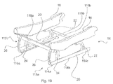
- the foot 14 according to FIG. 1 is formed by a web assembly 16 .
- This web assembly 16 has a first web 18 and a second web 20 .
- the first web 18 and the second web 20 run substantially horizontally and parallel to each other. In the vertical direction the first web 18 and the second web 20 are spaced from each other.
- the web assembly 16 furthermore has a third web 22 and a fourth web 24 .
- the third web 22 and fourth web 24 are spaced in the vertical direction.
- the third web 22 and fourth web 24 are coupled firstly with the first web 18 and secondly with the web 20 .
- the first web 18 , second web 20 , third web 22 and fourth web 24 form or define in cooperation a frame 26 .
- This frame 26 as shown in FIG. 1 spans/defines a plane.
- pivot points 28 , 30 , 32 , 34 via which the third web 22 and fourth web 24 are coupled to the first web 18 and second web 20 respectively can for example be formed by pivot points.
- Such pivots can for example be such that they are substantially free to swivel; they can also however be such that they are fitted with a self-retaining mechanism such as for example a friction mechanism so that—in relation to each of these pivots—a minimum pre-specified moment must act about this pivot on each of the adjacent webs 18 and 22 or 18 and 20 or 20 and 22 or 20 and 24 in order to achieve a swiveling of the webs 18 and 22 or 18 and 24 or 20 and 22 or 20 and 24 in relation to each other.
- the coupling or connecting points 28 or 30 or 32 or 34 can furthermore for example be formed in the manner of linear guides; these can for example be such that on the first web 18 and second web 20 grooves or similar are provided in which the third web 22 and fourth web 24 engage with their ends, or engagement parts provided there.
- the grooves extend in particular on the side of the first web 18 and second web 20 facing the third web 22 and fourth web 24 respectively, in particular in the longitudinal direction of these webs 18 , 20 . It can be provided that the grooves have a substantially U-shaped or rectangular cross section. Particularly preferably the grooves however have an L- or T-shaped cross section wherein they form an undercut or back cut, and wherein the respective engagement parts of the third web 22 and fourth web 24 are each formed L- or T-shaped and engage in the corresponding grooves.
- the webs 18 and 20 are additionally fixed with the webs 22 and 24 in the region of these grooves or pivots via weld points so that under a predetermined load, the weld points break or open and correspondingly by means of the longitudinal guides formed by the grooves or by means of the pivot point, in particular in cooperation with the at least one deformation device 36 discussed further below, the relative movement or relative swivel discussed further below of the webs 18 , 20 , 22 , 24 forming the frame 26 is allowed or occurs under corresponding load, in particular without the webs of the frame 26 being separated from each other.
- the deformation device 36 here can have a retaining and/or damping effect.
- the coupling or connecting points 28 or 30 or 32 or 34 can however also be formed differently than explained above as an example.
- the coupling or connecting points 28 or 30 or 32 or 34 are formed such that, in particular within the plane spanned by this frame, they allow a shift or swivel of the frame 26 formed by webs 18 , 20 , 22 , 24 such that the angle 38 , 40 , 42 , 44 formed between adjacent webs 16 and 20 or 16 and 22 or 18 and 20 or 18 and 24 changes or can change in particular under a predetermined load, without the adjacent webs 16 and 20 or 16 and 22 or 18 and 20 or 18 and 24 being separated from each other in the region of the coupling or connecting points 28 or 30 or 32 or 34 or without the coupling or connecting points 28 or 30 or 32 or 34 opening or being destroyed or breaking.
- the foot 14 as a whole i.e. at least in collaboration of webs 18 , 20 , 22 , 24 with the at least one deformation device 36 evidently has a supporting effect for the seating surface 10 or the unit of seating surface 10 and back rest 12 , even if the seating surface 10 is loaded by a passenger seated thereon.
- the foot 14 can withstand a load from above which is greater than 2000 N, preferably greater than 2500 N, preferably greater than 3000 N, preferably greater than 3500 N, preferably greater than 4000 N, preferably greater than 5000 N, preferably greater than 6000 N, preferably greater than 8000 N, preferably greater than 10,000 N, and in particular without causing said relative movement or shift or said swivel of the frame 26 or its webs 18 , 20 , 22 , 24 .
- the foot 14 furthermore has at least one deformation device 36 .
- the deformation device 36 extends inclined to the horizontal direction 46 and inclined to the vertical direction 48 .
- the deformation device 36 extends preferably only within the frame 26 and is coupled at its two end regions 50 , 52 with the frame 26 , for example coupled pivoting or welded. Between the coupling points 54 , 56 by means of which the deformation device 36 is coupled to the frame 26 , the deformation device 36 has at least one first section 58 in which it is folded or curved or bent or kinked or in particularly preferably runs flat.
- the frame 26 here has a trapezoid form.
- the deformation device 36 is structured such that its front coupling point 54 or coupling points 54 in the viewing direction of a person seated on the vehicle seat 1 with his back against the back rest 12 , is or are positioned below the rear coupling point 56 or coupling points 56 ; instead the deformation device 36 or devices 36 can be positioned so that the rear coupling point(s) 56 is or are positioned below the front coupling point(s) 54 . Also crossing deformation devices 36 can be provided in an alternative design.
- FIGS. 2 a and 2 b show a deformation device 36 which preferably extends at least partly substantially flat and preferably completely flat.
- the deformation device 36 has a length L 1 and width B 1 , where L 1 is preferably many times greater than B 1 . Furthermore the deformation device 36 has a height H which preferably constitutes a fraction of width B 1 .
- the deformation device 36 as well as a multiplicity of preferably elliptical or droplet-shaped holes 102 a - f , particularly preferably has in its end regions coupling devices 104 a and 104 b which can be connected to the coupling means formed on the web assembly 16 .
- the coupling devices 104 a and 104 b which preferably have partially straight or curved slots, are connected with the web assembly 16 in the regions of connecting points 28 and 34 , in particular at connecting points 28 and 34 and/or at one of the webs 22 or 18 or one of the webs 24 or 20 .
- the holes 102 a - f are preferably surrounded substantially by two wall areas 106 a , 106 b and spaced apart in length direction L 1 by intermediate regions 108 .
- the wall areas 106 a , 106 b preferably form a one-piece or connected structure in the intermediate region 108 .
- FIG. 3 shows the deformation device 36 shown in FIGS. 2 a and 2 b in a perspective view.
- FIG. 4 shows the deformation device 36 shown in FIGS. 2 a , 2 b , and 3 arranged on the web assembly 16 .
- the web 20 is not shown in this view but is formed by the preferably stationary arrangement of connecting points 32 and 34 .
- FIG. 5 shows a diagrammatic depiction of web assembly 16 and deformation device 36 in the main configuration.
- the web assembly 16 in this depiction or configuration is a parallelogram in the form of a rectangle and the deformation device 36 extends diagonally from the area of the coupling or connecting point 34 to the coupling or connecting point 28 .
- FIG. 6 shows a further diagrammatic depiction of the web assembly 16 and deformation device 36 in deformation configuration.
- the web assembly 16 in this depiction is shown in the form of a lozenge, whereby the distance between the coupling or connecting points 28 and 34 is extended in comparison with the main configuration shown in FIG. 5 .
- this leads to a distortion of the deformation device 36 on deflection of the web assembly 16 , for example on rotation of the web assembly 16 about the coupling or connecting device 32 as a consequence of an accident, whereby kinetic energy is absorbed because of the plastic distortion of the deformation device 36 .
- FIG. 7 a shows a further embodiment of the vehicle seat 1 according to the invention.
- the vehicle seat 1 in this depiction is arranged inside a vehicle 110 and connected with the vehicle frame 112 .
- the vehicle seat 1 has a back rest 12 and a seating surface 10 , where it is conceivable that the back rest 12 is pivotable in relation to the seating surface 10 . It is furthermore conceivable that a table adjustable in position is arranged on the vehicle seat 1 .
- one or more arm rests can be arranged on the seat 1 .
- FIG. 7 b shows an enlarged view of the foot 14 of the vehicle seat 1 shown in FIG. 7 a .
- the foot 14 consists of four connecting means 18 , 20 , 22 , 24 , wherein it is conceivable that the first connecting means 18 is separate from the seating surface 10 or formed as one piece with this.
- the second connecting means 20 is arranged in the vertical direction below the first connecting means 18 .
- the first two connecting means 18 , 20 are spaced apart by the second connecting means 22 , 24 .
- the third connecting means 22 is formed substantially U-shaped and the fourth connecting means 24 is formed substantially S-shaped. It is furthermore clear from FIG.
- the second connecting means 20 can preferably be divided into several sections, namely a first section 114 a , a second section 114 b and a third section 114 c .
- the second section 114 b serves preferably to space the third and fourth connecting means or to connect with the third and fourth connecting means 22 , 24 and thus forms preferably the proportion of the connecting means 20 which with the further three connecting means 18 , 22 , 24 forms the frame of the foot 14 .
- the second section 114 b like the first and third sections 114 a , 114 c , can be designed to couple the vehicle seat 1 or foot 14 with the vehicle frame 112 .
- Reference numeral 36 designates the deformation device which is preferably connected by its first end with the frame in the region of the first connecting means 18 and/or in the upper region of the fourth connecting means 24 and with its second end is arranged preferably in section 114 a of the second connecting means 20 lying outside the frame. It is also conceivable that the deformation device 36 is not connected with the second connecting means 20 or its first section 114 a but with the vehicle 110 and in particular the vehicle frame 112 directly.
- FIG. 7 b furthermore shows that the deformation device 36 is bent and thus arranged without stress.
- FIGS. 8 a/b and 9 a/b show different inclines of the vehicle seat 1 and first connecting means 18 in relation to the second connecting means 20 . These inclines result for example on an accident and in particular on a force applied from the rear to the vehicle seat 1 , in particular the seat back 12 . It is clear from FIGS. 7 a to 9 b that the greater the incline, the length of the deformation device 36 changes, in particular is extended.
- the third and fourth connecting means 22 , 24 here carry out movements which are described in particular in a further patent application submitted by the applicant on the same day which is here by reference included in full in the object of the present patent application.
- FIG. 10 shows a three-dimensional depiction of a seat lower part according to the invention.
- Reference numerals 113 a/b designate a first foot 14 and a second foot 14 , where the feet 14 are preferably spaced from each other in the vehicle width direction via struts 118 a/b .
- the second connecting means 20 in this depiction has fixing means 116 a/b for fixing the vehicle seat or the second connecting means 20 to the vehicle frame 112 .
- the fixing means 116 a/b are holes to receive bolts, wherein it is also conceivable that the second connecting means 20 can be connected with the vehicle frame 112 e.g. by means of material connection, in particular by welding.
- two deformation devices 36 are provided, wherein it is conceivable that more than two deformation devices 36 can be provided, in particular three, four or five deformation devices 36 of the same or similar design.
Landscapes
- Engineering & Computer Science (AREA)
- Aviation & Aerospace Engineering (AREA)
- Transportation (AREA)
- Mechanical Engineering (AREA)
- Seats For Vehicles (AREA)
- Passenger Equipment (AREA)
Abstract
Description
- 1 Vehicle seat
- 10 Seating surface of 1
- 12 Back rest of 1
- 14 Foot of 1
- 16 Web assembly of 1
- 18 First web or first connecting means of 16
- 20 Second web or second connecting means of 16
- 22 Third web or third connecting means of 16
- 24 Fourth web or fourth connecting means of 16
- 26 Frame
- 28 Coupling or connecting point between 18 and 22
- 30 Coupling or connecting point between 18 and 24
- 32 Coupling or connecting point between 20 and 22
- 34 Coupling or connecting point between 20 and 24
- 36 Fifth web/deformation device
- 38 Angle between 18 and 22
- 40 Angle between 18 and 24
- 42 Angle between 20 and 22
- 44 Angle between 20 and 24
- 46 Horizontal direction
- 48 Vertical direction
- 50 End region of 36
- 52 End region of 36
- 54 Coupling point for coupling of 36 with 26
- 56 Coupling point for coupling of 36 with 26
- 58 First section of 36
- 102 a-f Holes
- 104 a/b Coupling devices
- 106 a/b Wall regions
- 110 Vehicle
- 112 Vehicle frame
- 113 a/
b First foot 14,second foot 14 - 114 a-c First to third sections of connecting
means 20 - 116 a/b Fixing means
- 118 a/b Struts
- L1 Length of
deformation device 36 - B1 Width of
deformation device 36 - H Height of
deformation device 36
Claims (13)
Applications Claiming Priority (5)
| Application Number | Priority Date | Filing Date | Title |
|---|---|---|---|
| DE102010035996 | 2010-08-31 | ||
| DE102010035996.3 | 2010-08-31 | ||
| DE102010051326.1 | 2010-11-16 | ||
| DE102010051326 | 2010-11-16 | ||
| DE102010051326A DE102010051326A1 (en) | 2010-08-31 | 2010-11-16 | Vehicle seat for vehicles |
Publications (2)
| Publication Number | Publication Date |
|---|---|
| US20120049602A1 US20120049602A1 (en) | 2012-03-01 |
| US8926012B2 true US8926012B2 (en) | 2015-01-06 |
Family
ID=45566276
Family Applications (1)
| Application Number | Title | Priority Date | Filing Date |
|---|---|---|---|
| US13/216,537 Expired - Fee Related US8926012B2 (en) | 2010-08-31 | 2011-08-24 | Vehicle seats for vehicles |
Country Status (4)
| Country | Link |
|---|---|
| US (1) | US8926012B2 (en) |
| CN (1) | CN102555861B (en) |
| BR (1) | BRPI1104652B1 (en) |
| DE (1) | DE102010051326A1 (en) |
Cited By (4)
| Publication number | Priority date | Publication date | Assignee | Title |
|---|---|---|---|---|
| US20140332656A1 (en) * | 2013-05-08 | 2014-11-13 | Dr. Ing. H.C. F. Porsche Aktiengesellschaft | Adjustment arrangement for a motor vehicle seat |
| US10065541B2 (en) | 2015-08-10 | 2018-09-04 | Grammer Ag | Horizontal vibration device for a vehicle seat |
| US10150392B2 (en) * | 2016-02-24 | 2018-12-11 | Ayyakannu Mani | Combat vehicle seat installation for protection of occupants from the effects of ground explosions |
| US10850650B2 (en) * | 2018-09-12 | 2020-12-01 | Toyota Jidosha Kabushiki Kaisha | Vehicle seat |
Families Citing this family (10)
| Publication number | Priority date | Publication date | Assignee | Title |
|---|---|---|---|---|
| US8500196B2 (en) * | 2008-04-15 | 2013-08-06 | Britax Child Safety, Inc. | Child seat having a crush zone |
| DE102010033028B4 (en) | 2010-08-02 | 2014-02-27 | Grammer Aktiengesellschaft | Vehicle vibration device with a horizontal suspension device |
| DE102010033419A1 (en) * | 2010-08-04 | 2012-02-09 | Grammer Aktiengesellschaft | Horizon spring device for vehicle seats with elastomer spring element with progressive spring characteristic |
| DE102010052619A1 (en) | 2010-11-29 | 2012-05-31 | Grammer Aktiengesellschaft | Vehicle seat with guided scissor arms |
| DE102010053752A1 (en) | 2010-12-08 | 2012-06-14 | Grammer Aktiengesellschaft | Vehicle vibration device for vehicle seats or vehicle cabins |
| DE102010054749B4 (en) | 2010-12-15 | 2013-10-24 | Grammer Aktiengesellschaft | Suspension device for vehicle seats and / or vehicle cabins with elastomeric element |
| DE102011053647B4 (en) | 2011-09-15 | 2022-02-03 | Grammer Aktiengesellschaft | Vehicle seat with a suspension device and motor vehicle |
| CN102356974A (en) * | 2011-09-20 | 2012-02-22 | 好孩子儿童用品有限公司 | Member bar, and infant bounce chair and infant stroller having same |
| US9051053B2 (en) * | 2013-01-10 | 2015-06-09 | Textron Innovations, Inc. | Seat base for aircraft |
| DE102016112106B4 (en) * | 2016-07-01 | 2019-07-04 | Grammer Ag | suspension device |
Citations (166)
| Publication number | Priority date | Publication date | Assignee | Title |
|---|---|---|---|---|
| US203739A (en) | 1878-05-14 | Improvement in springs for seats | ||
| US1544248A (en) | 1924-06-21 | 1925-06-30 | Hugh Mcleod | Spring seat support |
| US1607164A (en) | 1925-01-29 | 1926-11-16 | Int Motor Co | Cushion connection for vehicle construction |
| US1945801A (en) | 1932-07-20 | 1934-02-06 | Briggs & Stratton Corp | Vehicle leaf spring construction |
| US1948476A (en) | 1930-08-13 | 1934-02-20 | Firestone Tire & Rubber Co | Rubber shock and vibration insulator |
| US2489981A (en) | 1946-03-20 | 1949-11-29 | Harold C Rose | Seat suspension for all implements |
| US2559105A (en) | 1945-09-22 | 1951-07-03 | Jr Thomas A Banning | Automobile spring and the like |
| US2607397A (en) | 1948-09-25 | 1952-08-19 | Schneider Charles | Chair construction having a spring support |
| US2686667A (en) | 1950-01-14 | 1954-08-17 | Nat Malleable & Steel Castings | Cushioning device |
| US2933127A (en) * | 1958-04-11 | 1960-04-19 | Aerotec Ind Inc | Seats for conveyances |
| US3046053A (en) | 1960-10-21 | 1962-07-24 | Bunting Company Inc | Glider construction |
| US3134568A (en) | 1962-03-22 | 1964-05-26 | Raymond M Carson | Tractor seat mount |
| US3208085A (en) | 1961-06-22 | 1965-09-28 | Vitafoam Ltd | Resilient cushion |
| US3298654A (en) | 1965-02-15 | 1967-01-17 | Artnell Company | Vehicle seat support |
| US3436042A (en) | 1966-04-05 | 1969-04-01 | Imexin Sa Nv | Vibration dampening pads |
| DE1480188A1 (en) | 1965-12-15 | 1970-03-26 | Schehl Dr Ernst | Motor vehicle seat |
| DE1405350A1 (en) | 1958-02-18 | 1970-03-26 | Mueller Wilhelm H & Co Kg | Cushioning device, especially for driver's seats with parallel seat shells |
| US3578376A (en) * | 1968-09-20 | 1971-05-11 | Toyota Motor Co Ltd | Seat construction of a vehicle |
| US3608855A (en) | 1968-02-27 | 1971-09-28 | Bremshey & Co | Adjustable seating structure, particularly for automobiles |
| US3697128A (en) * | 1968-12-05 | 1972-10-10 | Recaro Ag | Motor vehicle seat |
| US3724603A (en) * | 1971-07-13 | 1973-04-03 | Toyota Motor Co Ltd | Collision force absorption device |
| US3756556A (en) | 1971-07-01 | 1973-09-04 | Ivac Corp | Fluid flow control apparatus |
| DE2309808A1 (en) | 1972-02-26 | 1973-09-20 | Chapman Ltd A W | HEIGHT ADJUSTABLE SEAT |
| DE2317824A1 (en) | 1972-04-12 | 1973-10-25 | Parallellsystem Fa | SEAT FOR TUGS AND OTHER VEHICLES |
| US3788697A (en) | 1972-04-06 | 1974-01-29 | Caterpillar Tractor Co | Vehicle seat |
| US3802737A (en) * | 1972-07-07 | 1974-04-09 | Heizer K | Safety seat, particularly for automotive vehicles |
| DE7419891U (en) | 1974-06-10 | 1974-10-17 | Hagmeier G | VEHICLE SEAT |
| US3883172A (en) | 1973-07-02 | 1975-05-13 | Caterpillar Tractor Co | Vehicular seat mounting linkage |
| US3882956A (en) | 1970-06-18 | 1975-05-13 | Chausson Usines Sa | Suspension device for vehicle drivers cab |
| GB1401881A (en) | 1971-07-21 | 1975-08-06 | Gomma Antivibranti Applic | Vehicle suspensions |
| US3917209A (en) | 1973-07-24 | 1975-11-04 | Chapman Ltd A W | Vehicle seat support |
| US4002315A (en) | 1974-05-21 | 1977-01-11 | N.V. Imexin S.A. | Vibration damper |
| DE2537174A1 (en) | 1975-08-21 | 1977-03-03 | Rudolf Ing Grad Steigerwald | Lateral damping for vehicle seat - with pendant damped suspension on vertically sprung frame able to accommodate different driver weights |
| US4022411A (en) | 1975-06-27 | 1977-05-10 | Royal Industries, Inc. | Self-levelling seat suspension system for vehicles |
| DE7731339U1 (en) | 1977-10-11 | 1978-01-26 | Fa. Willibald Grammer, 8450 Amberg | VEHICLE SEAT |
| DE1480465C3 (en) | 1964-05-14 | 1978-10-05 | Michel Antoine Emile Jurens Valleiry Haute-Savoie Vuichard (Frankreich) | Suspension for vehicle seats |
| DE2816616A1 (en) | 1978-04-17 | 1979-10-25 | Weltin Optac | Plate shaped machine vibration damper - has rubber and elastomer plates with interfitting conical projections and recesses |
| US4257626A (en) * | 1978-03-07 | 1981-03-24 | Repa Feinstanzwerk Gmbh | Device for tightening a safety belt for a motor vehicle |
| GB1587637A (en) | 1976-05-24 | 1981-04-08 | Deere & Co | Suspension mechanism for a vehicle seat |
| US4273213A (en) | 1977-11-09 | 1981-06-16 | Erich Munz | Element for sonic and vibratory absorption |
| DE3003175A1 (en) | 1980-01-30 | 1981-08-06 | Keiper Automobiltechnik Gmbh & Co Kg, 5630 Remscheid | Rake adjustment for car seat - has spindle drive with servo driven coaxial worm gear |
| US4349167A (en) * | 1979-10-30 | 1982-09-14 | The Boeing Company | Crash load attenuating passenger seat |
| US4440441A (en) * | 1981-12-17 | 1984-04-03 | Fairchild Industries, Inc. | Energy attenuating seat and leg therefor |
| DE3237167A1 (en) * | 1982-10-07 | 1984-04-12 | Volkswagenwerk Ag, 3180 Wolfsburg | Vehicle seat |
| US4487383A (en) * | 1982-09-29 | 1984-12-11 | Ara, Inc. | Crashworthy rear-facing passenger seat for fixed wing aircraft |
| US4500076A (en) | 1981-03-10 | 1985-02-19 | Rova Jan Erik | Arrangement in spring suspension systems particularly for vehicles |
| US4519591A (en) | 1982-08-20 | 1985-05-28 | Bush John W | Non-metallic leaf spring structure |
| US4529158A (en) | 1983-05-16 | 1985-07-16 | Itt Corporation | Adjustable vehicle seat mechanism |
| US4678155A (en) | 1986-12-12 | 1987-07-07 | The Wise Company, Inc. | Mechanism on a vehicle seat for adjusting stiffness of ride |
| US4679760A (en) | 1985-05-14 | 1987-07-14 | Grammer Sitzsysteme Gmbh | Spring arrangement |
| US4714227A (en) | 1986-11-17 | 1987-12-22 | Deere & Company | Seat suspension for an off-road vehicle |
| US4842257A (en) | 1987-11-13 | 1989-06-27 | General Motors Corporation | Vehicle seat suspension component and its method of manufacture |
| US4859148A (en) | 1988-02-26 | 1989-08-22 | United Technologies Corporation | Preloaded tunable elastomeric flapping hinge bearing and method of preloading |
| DE3890533T1 (en) | 1987-06-26 | 1989-10-19 | Seats Inc | SEAT SUSPENSION WITH VIBRATION COMPENSATION |
| US4911381A (en) * | 1987-12-28 | 1990-03-27 | Simula, Inc. | Energy-absorbing leg assembly for aircraft passenger seats |
| US4927119A (en) | 1986-02-24 | 1990-05-22 | Kimball Industries, Inc. | Reversible flow valve for air isolated bases |
| DE3901898A1 (en) | 1989-01-23 | 1990-07-26 | Wolf Woco & Co Franz J | AREA STORAGE AND METHOD FOR THE PRODUCTION THEREOF |
| US4954051A (en) | 1987-10-02 | 1990-09-04 | National Seating Company | Air spring seat and air pump |
| US4958812A (en) | 1986-11-03 | 1990-09-25 | Woco Franz-Josef Wolf & Co. | Suspension spring system |
| US5004206A (en) | 1990-01-26 | 1991-04-02 | Scott Anderson | Vehicle seat mounting structure |
| US5014960A (en) | 1988-03-13 | 1991-05-14 | Tachi-S Co., Ltd. | Fore-and-aft suspension device for automotive seat |
| US5054753A (en) | 1988-05-13 | 1991-10-08 | Michael Polus | Damping device for shock loading |
| US5087503A (en) | 1989-09-14 | 1992-02-11 | Pacific Coast Composites, Inc. | Composite constant stress beam with gradient fiber distribution |
| WO1992004224A1 (en) | 1990-08-30 | 1992-03-19 | Malå Skogstjänst Ab | Cabin, especially for a cross-country vehicle |
| WO1992009451A1 (en) | 1990-11-30 | 1992-06-11 | Keiper Recaro S.P.A. | A sport seat for motor vehicles |
| US5123625A (en) | 1989-11-24 | 1992-06-23 | Paulstra G.M.B.H. | Resilient support element with graded stiffnesses |
| US5127699A (en) | 1988-04-18 | 1992-07-07 | Kubota Tekko Kabushiki Kaisha | Device for reversibly supporting seat for vehicles |
| US5194111A (en) | 1989-09-14 | 1993-03-16 | Pacific Coast Composites, Inc. | Composite constant stress beam with gradient fiber distribution |
| US5221071A (en) | 1991-11-15 | 1993-06-22 | Milsco Manufacturing Company | Vehicle seat suspension with improved compression spring mounting |
| US5222709A (en) | 1990-04-13 | 1993-06-29 | Rosdon Engineering And Manufacturing Pty. Ltd. | Vehicle seat suspension unit |
| DE9312640U1 (en) | 1992-08-31 | 1994-01-13 | Deere & Company, Niederlassung Deere & Co. European Office, Mannheim, Moline, Ill. | Driver platform suspension for vehicles |
| EP0284365B1 (en) | 1987-03-23 | 1994-06-08 | Richard J. Yarger | Aspirator sleeve |
| US5324095A (en) * | 1991-08-27 | 1994-06-28 | Ikeda Bussan Co., Ltd. | Suspension seat |
| US5331750A (en) | 1987-05-28 | 1994-07-26 | Sumitomo Rubber Industries, Ltd. | Shock absorbing structure |
| US5338090A (en) * | 1991-05-09 | 1994-08-16 | Koito Industries, Ltd. | Leg structure of seat for absorbing impact energy |
| US5344210A (en) * | 1991-01-22 | 1994-09-06 | Sicma Aero Seat Societe Industrielle Et Commerciale De Materiel Aeronautique | Energy-absorbing device, structure forming a mounting for an aircraft seat having such a device, and seat having such a structure |
| US5358210A (en) | 1992-03-31 | 1994-10-25 | Hutchinson | Device for filtering vibration, and a fixing system comprising a plurality of such devices for fixing a load on a support |
| US5437494A (en) | 1992-10-29 | 1995-08-01 | Life Force Associates, L.P. | Rearward moving seat |
| US5449218A (en) | 1988-01-07 | 1995-09-12 | Life Force, Inc. | Vehicle safety device |
| US5531404A (en) * | 1993-05-14 | 1996-07-02 | Societe Industrielle Et Commerciale De Materiel Aeronautique | Underframe for a passenger aircraft seat, and a seat including such an underframe |
| US5555501A (en) | 1994-01-27 | 1996-09-10 | Isuzu Motors, Ltd. | Road vehicle cab attitude controlling apparatus |
| US5553911A (en) | 1994-12-15 | 1996-09-10 | Volvo Gm Heavy Truck Corporation | Heavy duty motor vehicle cab suspension |
| US5632208A (en) | 1995-11-13 | 1997-05-27 | National Castings Incorporated | Multi-axle railroad car truck |
| US5651585A (en) | 1994-02-25 | 1997-07-29 | Seats, Inc. | Knee action suspension seat |
| US5657950A (en) * | 1995-08-14 | 1997-08-19 | Industrial Technology Research Intitute | Backward-leaning-movement seat leg structure |
| US5730492A (en) * | 1996-02-09 | 1998-03-24 | Simula Inc. | Load-limiting seat |
| US5743592A (en) * | 1995-05-31 | 1998-04-28 | Societe Industrielle Et Commerciale De Materiel Aeronautique | Leg for an aircraft seat, a leg assembly including such a leg, and a seat including such a leg assembly |
| US5758859A (en) | 1996-02-12 | 1998-06-02 | U.S. Government As, Represented By The Secretary Of The Army | Shock absorbing vehicle seat assembly |
| WO1998032627A1 (en) | 1997-01-23 | 1998-07-30 | Lear Corporation | Vehicle seat assembly incorporating a one-piece shell as seat back and lower seat support |
| US5871257A (en) | 1997-12-24 | 1999-02-16 | Dundes, Sr.; Kenneth E. | Self-leveling seat |
| US5899288A (en) | 1997-11-12 | 1999-05-04 | Case Corporation | Active suspension system for a work vehicle |
| US5967604A (en) * | 1996-12-17 | 1999-10-19 | Aisin Seiki Kabushiki Kaisha | Vehicle seat apparatus |
| USH1833H (en) * | 1996-12-18 | 2000-02-01 | The United States Of America As Represented By The Secretary Of The Army | Apparatus for absorbing mine blast energy |
| DE19907658A1 (en) | 1999-02-23 | 2000-08-24 | Bayerische Motoren Werke Ag | Seat for a vehicle |
| DE19919697A1 (en) | 1999-04-30 | 2000-11-02 | Keiper Gmbh & Co | Vehicle seat, in particular motor vehicle rear seat |
| DE19945841A1 (en) | 1999-09-24 | 2001-04-05 | Audi Ag | Pad for supporting spring in a car wheel suspension comprises two metal plates shaped like sections of sphere with convex sides facing each other and separated by elastomeric buffer which acts as universal joint |
| US6286821B1 (en) | 2000-05-30 | 2001-09-11 | Ford Global Technologies, Inc. | Extruded stabilizer bar pivot bushing having plastic shear plates and method of making same |
| DE19744199C2 (en) | 1997-09-30 | 2002-01-17 | Brose Fahrzeugteile | Slide |
| US6354556B1 (en) | 1999-02-04 | 2002-03-12 | Freightliner Llc | Seat suspension method |
| US20020033622A1 (en) * | 2000-09-15 | 2002-03-21 | Mandeep Jarnail | Vehicle passenger seat |
| US6412864B1 (en) * | 2000-03-10 | 2002-07-02 | Be Aerospace, Inc. | Side facing multi-passenger divan assembly |
| US6478102B1 (en) | 2001-04-21 | 2002-11-12 | International Truck Intellectual Property Company, L.L.C. | Vehicle body suspension system |
| US6582015B2 (en) * | 2000-08-17 | 2003-06-24 | Chris P. Jessup | Seat and occupant restraint system with adaptable actuator |
| US6595570B2 (en) * | 2000-11-22 | 2003-07-22 | Lear Corporation | Vehicle seat assembly having load cell based seat occupant sensing system |
| DE10129127B4 (en) | 2001-06-16 | 2004-02-05 | Grammer Ag | vehicle seat |
| WO2003063650A3 (en) | 1997-09-30 | 2004-03-25 | Seat Revolution Inc | Two platform motion seat |
| US6725983B2 (en) | 2001-09-14 | 2004-04-27 | Meritor Heavy Vehicle Technology, Llc | Shock absorber with air pressure adjustable damping |
| US6758294B2 (en) | 2002-06-10 | 2004-07-06 | Volvo Trucks North America, Inc. | Laterally damped panhard rod cab suspension |
| US6773049B2 (en) | 2002-10-18 | 2004-08-10 | Deere & Co. | Adjustable seat suspension for utility vehicle |
| US6857674B2 (en) | 2002-09-19 | 2005-02-22 | Airbus France | Device and system for filtering vibrational movements of a passenger support, and passenger support equipped with such a system |
| US20050051373A1 (en) | 2002-07-19 | 2005-03-10 | Gerd Bernhardt | Vehicle cab mounting system |
| DE10206223B4 (en) | 2002-02-15 | 2005-08-04 | Grammer Ag | Scissor frame for a seat |
| EP1577156A2 (en) | 2004-03-17 | 2005-09-21 | DaimlerChrysler AG | Vehicle seat for a commercial vehicle |
| US20050224269A1 (en) | 2004-04-07 | 2005-10-13 | Deere & Company, A Delaware Corporation | Vehicle operator's platform |
| DE102005028725A1 (en) | 2004-06-22 | 2006-01-19 | Sears Manufacturing Co. | Vehicle seat suspension with omnidirectional buffer element |
| US20060061022A1 (en) | 2004-09-20 | 2006-03-23 | Hung-Shen Chang | Shock-absorbing device for wheeled vehicle |
| US7017888B2 (en) | 2003-09-05 | 2006-03-28 | Arvinmeritor Technology Llc | Attachment arrangement for a composite leaf spring which accommodates longitudinal movement through shear displacement |
| DE102005023088B3 (en) | 2005-05-13 | 2006-06-22 | Grammer Ag | Suspension for e.g. tractor seat, has controller, where removal and discharging of additional volumes is switched on or deactivated by controller so that distribution of force path spring characteristic line has no or small gradient |
| US7077226B2 (en) | 2002-08-21 | 2006-07-18 | Delphi Technologies,Inc. | Controlled truck cab suspension system |
| US7077227B2 (en) | 2002-08-21 | 2006-07-18 | Delphi Technologies, Inc. | Controlled truck cab suspension |
| US7080881B2 (en) * | 2004-09-17 | 2006-07-25 | B/E Aerospace, Inc. | Flexible seat frame |
| US20060208401A1 (en) | 2003-04-12 | 2006-09-21 | Detroit Steel Products Co Inc | Anti-roll leaf-spring suspension |
| US20060237885A1 (en) | 2003-03-04 | 2006-10-26 | Baultar I.D Inc. | Active seat suspension |
| US7201367B2 (en) | 2002-12-12 | 2007-04-10 | Caterpillar Inc | Load-bearing resilient mount |
| DE102006030008A1 (en) | 2005-07-03 | 2007-04-26 | Hermann Tropf | Device for connecting a component with a unit used in oscillation-absorbing and shock-absorbing fixtures comprises an oscillating mechanism coupled with either the component or unit to absorb shocks and vibrations |
| WO2007058572A1 (en) | 2005-11-18 | 2007-05-24 | Volvo Construction Equipment Holding Sweden Ab | Suspension device for a vehicle component |
| US7240754B2 (en) | 2004-06-14 | 2007-07-10 | Delphi Technologies, Inc. | Truck cab suspension control |
| US7300100B2 (en) | 2004-10-21 | 2007-11-27 | Cnh America Llc | Windrower cab mounting and suspension system |
| EP1652724B1 (en) | 2004-10-29 | 2008-01-09 | Bose Corporation | Active suspending |
| US7331627B2 (en) | 2005-05-19 | 2008-02-19 | Joel Dean Van Den Brink | Lateral control rod for a cab suspension system |
| DE112006002984T5 (en) | 2005-11-04 | 2008-10-09 | Scania Cv Ab (Publ) | A vehicle seat frame construction |
| US7452019B1 (en) | 2007-06-05 | 2008-11-18 | Toyota Motor Engineering & Manufacturing North America, Inc. | Sliding and stowing motor vehicle seat |
| US7469861B2 (en) | 2001-08-09 | 2008-12-30 | Virgin Atlantic Airways Limited | Seating system and a passenger accommodation unit for a vehicle |
| DE102007027320B3 (en) | 2007-06-14 | 2009-01-02 | Brose Fahrzeugteile Gmbh & Co. Kommanditgesellschaft, Coburg | Backrest for motor vehicle seat, has plastic insert provided between lower and upper parts in area of guiding link, where insert forms flange and local compensating plate for clearing direct surface contact between parts in area of link |
| US7478879B2 (en) | 2003-11-27 | 2009-01-20 | Garry Robinson | Seat with dual independently adjustable supports |
| US20090045000A1 (en) | 2007-08-17 | 2009-02-19 | Brown Keith R | Air ride system for a tractor cab |
| DE10300876B4 (en) | 2003-01-10 | 2009-04-16 | Dorma Gmbh + Co. Kg | Sliding piece for door closers or rotary vane drives |
| US20090205880A1 (en) | 2008-02-19 | 2009-08-20 | Hammonds Technical Services, Inc. | Omni-directional vehicle with elevatable observation platform |
| US20090284061A1 (en) | 2008-05-07 | 2009-11-19 | Gm Global Technology Operations, Inc. | Drive device for a motor vehicle swivel seat |
| US20100006364A1 (en) | 2008-07-10 | 2010-01-14 | Sears Manufacturing Company | Vehicle seat and split console assembly |
| DE102008023120B4 (en) | 2008-05-07 | 2010-06-10 | Keiper Gmbh & Co. Kg | Vehicle seat, in particular commercial vehicle seat |
| DE102008063812A1 (en) | 2008-12-19 | 2010-06-24 | Zf Friedrichshafen Ag | Suspension device with roll compensation |
| US7744149B2 (en) | 2008-06-10 | 2010-06-29 | Agco Corporation | Cab suspension linkage system |
| US20100213345A1 (en) | 2005-05-13 | 2010-08-26 | Grammer Ag | Device and Method for Suspension of a Vehicle Seat by Means of Additional Volumes |
| US20100276211A1 (en) | 2009-04-02 | 2010-11-04 | Grammer Ag | Detection Device and Method for Detecting Occupancy of a Seat |
| US7882914B2 (en) | 2006-01-19 | 2011-02-08 | Husqvarna Professional Outdoor Products Inc. | Operator platform isolation system |
| US7883135B2 (en) * | 2004-03-18 | 2011-02-08 | Plasan Sasa Ltd. | Energy absorbing device for a vehicle seat |
| GB2438090B (en) | 2006-05-11 | 2011-07-13 | Technicon Internat Man Services Ltd | Improved seat |
| US7997600B2 (en) | 2007-11-24 | 2011-08-16 | Grammer Ag | Apparatus comprising a suspension system and method for adjusting a suspension system |
| US20110233975A1 (en) * | 2008-10-07 | 2011-09-29 | Mobius Protection Systems Ltd. | Shock absorbing mechanism with feet protection for vehicle and aircraft seats |
| US8061770B2 (en) * | 2007-12-19 | 2011-11-22 | C. Rob. Hammerstein Gmbh & Co. Kg | Motor vehicle seat with an underframe, a seat carrier and a seat back |
| US8095268B2 (en) | 2004-10-29 | 2012-01-10 | Bose Corporation | Active suspending |
| US20120007293A1 (en) | 2010-07-08 | 2012-01-12 | Grammer Ag | Seat suspension device for a vehicle seat |
| US20120025577A1 (en) | 2010-08-02 | 2012-02-02 | Grammer Ag | Horizontal springing means with inclination compensation |
| US20120032379A1 (en) | 2010-08-04 | 2012-02-09 | Grammer Ag | Horizontal springing device for vehicle seats with elastomer spring element with progressive spring characteristic curve |
| US20120043798A1 (en) | 2010-08-18 | 2012-02-23 | Grammer Ag | Vehicle suspension device for vehicle seats or vehicle cabs |
| US8182038B2 (en) | 2008-05-03 | 2012-05-22 | Grammer Ag | Vehicle seat having a device for controlling a pneumatic suspension system |
| US8186475B2 (en) | 2010-05-12 | 2012-05-29 | Metalcraft Of Mayville, Inc. | Suspended operator platform |
| US20120133184A1 (en) | 2010-11-29 | 2012-05-31 | Grammer Ag | Vehicle seat with guided scissor arms |
| US20120145875A1 (en) | 2010-12-08 | 2012-06-14 | Grammer Ag | Vehicle vibration device for vehicle seats or vehicle cabs |
| US20120153551A1 (en) | 2010-12-15 | 2012-06-21 | Grammer Ag | Suspension device for vehicle seats and/or vehicle cabins having an elastomer member |
| US8225903B2 (en) | 2009-11-12 | 2012-07-24 | Macdon Industries Ltd. | Cab suspension |
| US8226163B1 (en) * | 2009-02-06 | 2012-07-24 | Goodrich Corporation | Aircraft divan |
| US8261869B2 (en) | 2009-02-26 | 2012-09-11 | Cnh America Llc | Agricultural vehicle suspension |
| US8265832B2 (en) | 2007-10-08 | 2012-09-11 | Grammer Ag | Vehicle comprising a spring-mounted vehicle seat and a spring-mounted vehicle cab, and suspension method |
| US20130069409A1 (en) | 2011-09-15 | 2013-03-21 | Grammer Ag | Vehicle seat, motor vehicle and method for spring-mounting a vehicle seat |
Family Cites Families (1)
| Publication number | Priority date | Publication date | Assignee | Title |
|---|---|---|---|---|
| US2682931A (en) * | 1950-03-03 | 1954-07-06 | Victor M Young | Means for absorbing energy due to sudden impact |
-
2010
- 2010-11-16 DE DE102010051326A patent/DE102010051326A1/en not_active Withdrawn
-
2011
- 2011-08-24 US US13/216,537 patent/US8926012B2/en not_active Expired - Fee Related
- 2011-08-29 CN CN201110251166.7A patent/CN102555861B/en not_active Expired - Fee Related
- 2011-08-29 BR BRPI1104652-0A patent/BRPI1104652B1/en not_active IP Right Cessation
Patent Citations (179)
| Publication number | Priority date | Publication date | Assignee | Title |
|---|---|---|---|---|
| US203739A (en) | 1878-05-14 | Improvement in springs for seats | ||
| US1544248A (en) | 1924-06-21 | 1925-06-30 | Hugh Mcleod | Spring seat support |
| US1607164A (en) | 1925-01-29 | 1926-11-16 | Int Motor Co | Cushion connection for vehicle construction |
| US1948476A (en) | 1930-08-13 | 1934-02-20 | Firestone Tire & Rubber Co | Rubber shock and vibration insulator |
| US1945801A (en) | 1932-07-20 | 1934-02-06 | Briggs & Stratton Corp | Vehicle leaf spring construction |
| US2559105A (en) | 1945-09-22 | 1951-07-03 | Jr Thomas A Banning | Automobile spring and the like |
| US2489981A (en) | 1946-03-20 | 1949-11-29 | Harold C Rose | Seat suspension for all implements |
| US2607397A (en) | 1948-09-25 | 1952-08-19 | Schneider Charles | Chair construction having a spring support |
| US2686667A (en) | 1950-01-14 | 1954-08-17 | Nat Malleable & Steel Castings | Cushioning device |
| DE1405350A1 (en) | 1958-02-18 | 1970-03-26 | Mueller Wilhelm H & Co Kg | Cushioning device, especially for driver's seats with parallel seat shells |
| US2933127A (en) * | 1958-04-11 | 1960-04-19 | Aerotec Ind Inc | Seats for conveyances |
| US3046053A (en) | 1960-10-21 | 1962-07-24 | Bunting Company Inc | Glider construction |
| US3208085A (en) | 1961-06-22 | 1965-09-28 | Vitafoam Ltd | Resilient cushion |
| US3134568A (en) | 1962-03-22 | 1964-05-26 | Raymond M Carson | Tractor seat mount |
| DE1480465C3 (en) | 1964-05-14 | 1978-10-05 | Michel Antoine Emile Jurens Valleiry Haute-Savoie Vuichard (Frankreich) | Suspension for vehicle seats |
| US3298654A (en) | 1965-02-15 | 1967-01-17 | Artnell Company | Vehicle seat support |
| DE1480188A1 (en) | 1965-12-15 | 1970-03-26 | Schehl Dr Ernst | Motor vehicle seat |
| US3436042A (en) | 1966-04-05 | 1969-04-01 | Imexin Sa Nv | Vibration dampening pads |
| US3608855A (en) | 1968-02-27 | 1971-09-28 | Bremshey & Co | Adjustable seating structure, particularly for automobiles |
| US3578376A (en) * | 1968-09-20 | 1971-05-11 | Toyota Motor Co Ltd | Seat construction of a vehicle |
| US3697128A (en) * | 1968-12-05 | 1972-10-10 | Recaro Ag | Motor vehicle seat |
| US3882956A (en) | 1970-06-18 | 1975-05-13 | Chausson Usines Sa | Suspension device for vehicle drivers cab |
| US3756556A (en) | 1971-07-01 | 1973-09-04 | Ivac Corp | Fluid flow control apparatus |
| US3724603A (en) * | 1971-07-13 | 1973-04-03 | Toyota Motor Co Ltd | Collision force absorption device |
| GB1401881A (en) | 1971-07-21 | 1975-08-06 | Gomma Antivibranti Applic | Vehicle suspensions |
| DE2309808A1 (en) | 1972-02-26 | 1973-09-20 | Chapman Ltd A W | HEIGHT ADJUSTABLE SEAT |
| US3847338A (en) | 1972-02-26 | 1974-11-12 | Chapman A Ltd | Adjustable height seat |
| US3788697A (en) | 1972-04-06 | 1974-01-29 | Caterpillar Tractor Co | Vehicle seat |
| DE2317824A1 (en) | 1972-04-12 | 1973-10-25 | Parallellsystem Fa | SEAT FOR TUGS AND OTHER VEHICLES |
| GB1432614A (en) | 1972-04-12 | 1976-04-22 | Alden L A G Parallelsyst | Seats for tractors and other vehicles |
| US3802737A (en) * | 1972-07-07 | 1974-04-09 | Heizer K | Safety seat, particularly for automotive vehicles |
| US3883172A (en) | 1973-07-02 | 1975-05-13 | Caterpillar Tractor Co | Vehicular seat mounting linkage |
| US3917209A (en) | 1973-07-24 | 1975-11-04 | Chapman Ltd A W | Vehicle seat support |
| US4002315A (en) | 1974-05-21 | 1977-01-11 | N.V. Imexin S.A. | Vibration damper |
| DE7419891U (en) | 1974-06-10 | 1974-10-17 | Hagmeier G | VEHICLE SEAT |
| US4022411A (en) | 1975-06-27 | 1977-05-10 | Royal Industries, Inc. | Self-levelling seat suspension system for vehicles |
| DE2537174A1 (en) | 1975-08-21 | 1977-03-03 | Rudolf Ing Grad Steigerwald | Lateral damping for vehicle seat - with pendant damped suspension on vertically sprung frame able to accommodate different driver weights |
| GB1587637A (en) | 1976-05-24 | 1981-04-08 | Deere & Co | Suspension mechanism for a vehicle seat |
| FR2352686B1 (en) | 1976-05-24 | 1981-04-30 | Deere & Co | |
| DE7731339U1 (en) | 1977-10-11 | 1978-01-26 | Fa. Willibald Grammer, 8450 Amberg | VEHICLE SEAT |
| US4183492A (en) | 1977-10-11 | 1980-01-15 | Willibald Grammer | Vehicle seat |
| US4273213A (en) | 1977-11-09 | 1981-06-16 | Erich Munz | Element for sonic and vibratory absorption |
| US4257626A (en) * | 1978-03-07 | 1981-03-24 | Repa Feinstanzwerk Gmbh | Device for tightening a safety belt for a motor vehicle |
| DE2816616A1 (en) | 1978-04-17 | 1979-10-25 | Weltin Optac | Plate shaped machine vibration damper - has rubber and elastomer plates with interfitting conical projections and recesses |
| US4349167A (en) * | 1979-10-30 | 1982-09-14 | The Boeing Company | Crash load attenuating passenger seat |
| DE3003175A1 (en) | 1980-01-30 | 1981-08-06 | Keiper Automobiltechnik Gmbh & Co Kg, 5630 Remscheid | Rake adjustment for car seat - has spindle drive with servo driven coaxial worm gear |
| US4500076A (en) | 1981-03-10 | 1985-02-19 | Rova Jan Erik | Arrangement in spring suspension systems particularly for vehicles |
| DE3208680C2 (en) | 1981-03-10 | 1991-10-24 | Jan-Erik Kiruna Se Rova | |
| US4440441A (en) * | 1981-12-17 | 1984-04-03 | Fairchild Industries, Inc. | Energy attenuating seat and leg therefor |
| US4519591A (en) | 1982-08-20 | 1985-05-28 | Bush John W | Non-metallic leaf spring structure |
| US4487383A (en) * | 1982-09-29 | 1984-12-11 | Ara, Inc. | Crashworthy rear-facing passenger seat for fixed wing aircraft |
| DE3237167A1 (en) * | 1982-10-07 | 1984-04-12 | Volkswagenwerk Ag, 3180 Wolfsburg | Vehicle seat |
| US4529158A (en) | 1983-05-16 | 1985-07-16 | Itt Corporation | Adjustable vehicle seat mechanism |
| US4679760A (en) | 1985-05-14 | 1987-07-14 | Grammer Sitzsysteme Gmbh | Spring arrangement |
| DE3517345C2 (en) | 1985-05-14 | 1988-06-01 | Grammer Sitzsysteme Gmbh, 8450 Amberg, De | |
| US4927119A (en) | 1986-02-24 | 1990-05-22 | Kimball Industries, Inc. | Reversible flow valve for air isolated bases |
| US4958812A (en) | 1986-11-03 | 1990-09-25 | Woco Franz-Josef Wolf & Co. | Suspension spring system |
| US4714227A (en) | 1986-11-17 | 1987-12-22 | Deere & Company | Seat suspension for an off-road vehicle |
| US4678155A (en) | 1986-12-12 | 1987-07-07 | The Wise Company, Inc. | Mechanism on a vehicle seat for adjusting stiffness of ride |
| EP0284365B1 (en) | 1987-03-23 | 1994-06-08 | Richard J. Yarger | Aspirator sleeve |
| US5331750A (en) | 1987-05-28 | 1994-07-26 | Sumitomo Rubber Industries, Ltd. | Shock absorbing structure |
| DE3890533T1 (en) | 1987-06-26 | 1989-10-19 | Seats Inc | SEAT SUSPENSION WITH VIBRATION COMPENSATION |
| US4954051A (en) | 1987-10-02 | 1990-09-04 | National Seating Company | Air spring seat and air pump |
| US4842257A (en) | 1987-11-13 | 1989-06-27 | General Motors Corporation | Vehicle seat suspension component and its method of manufacture |
| US4911381A (en) * | 1987-12-28 | 1990-03-27 | Simula, Inc. | Energy-absorbing leg assembly for aircraft passenger seats |
| US5449218A (en) | 1988-01-07 | 1995-09-12 | Life Force, Inc. | Vehicle safety device |
| US4859148A (en) | 1988-02-26 | 1989-08-22 | United Technologies Corporation | Preloaded tunable elastomeric flapping hinge bearing and method of preloading |
| US5014960A (en) | 1988-03-13 | 1991-05-14 | Tachi-S Co., Ltd. | Fore-and-aft suspension device for automotive seat |
| US5127699A (en) | 1988-04-18 | 1992-07-07 | Kubota Tekko Kabushiki Kaisha | Device for reversibly supporting seat for vehicles |
| US5054753A (en) | 1988-05-13 | 1991-10-08 | Michael Polus | Damping device for shock loading |
| DE3901898A1 (en) | 1989-01-23 | 1990-07-26 | Wolf Woco & Co Franz J | AREA STORAGE AND METHOD FOR THE PRODUCTION THEREOF |
| US5087503A (en) | 1989-09-14 | 1992-02-11 | Pacific Coast Composites, Inc. | Composite constant stress beam with gradient fiber distribution |
| US5194111A (en) | 1989-09-14 | 1993-03-16 | Pacific Coast Composites, Inc. | Composite constant stress beam with gradient fiber distribution |
| US5123625A (en) | 1989-11-24 | 1992-06-23 | Paulstra G.M.B.H. | Resilient support element with graded stiffnesses |
| US5004206A (en) | 1990-01-26 | 1991-04-02 | Scott Anderson | Vehicle seat mounting structure |
| US5222709A (en) | 1990-04-13 | 1993-06-29 | Rosdon Engineering And Manufacturing Pty. Ltd. | Vehicle seat suspension unit |
| WO1992004224A1 (en) | 1990-08-30 | 1992-03-19 | Malå Skogstjänst Ab | Cabin, especially for a cross-country vehicle |
| WO1992009451A1 (en) | 1990-11-30 | 1992-06-11 | Keiper Recaro S.P.A. | A sport seat for motor vehicles |
| US5344210A (en) * | 1991-01-22 | 1994-09-06 | Sicma Aero Seat Societe Industrielle Et Commerciale De Materiel Aeronautique | Energy-absorbing device, structure forming a mounting for an aircraft seat having such a device, and seat having such a structure |
| US5338090A (en) * | 1991-05-09 | 1994-08-16 | Koito Industries, Ltd. | Leg structure of seat for absorbing impact energy |
| US5324095A (en) * | 1991-08-27 | 1994-06-28 | Ikeda Bussan Co., Ltd. | Suspension seat |
| US5221071A (en) | 1991-11-15 | 1993-06-22 | Milsco Manufacturing Company | Vehicle seat suspension with improved compression spring mounting |
| US5358210A (en) | 1992-03-31 | 1994-10-25 | Hutchinson | Device for filtering vibration, and a fixing system comprising a plurality of such devices for fixing a load on a support |
| US5368118A (en) | 1992-08-31 | 1994-11-29 | Deere & Company | Torsion bar suspension for operator's platform |
| DE9312640U1 (en) | 1992-08-31 | 1994-01-13 | Deere & Company, Niederlassung Deere & Co. European Office, Mannheim, Moline, Ill. | Driver platform suspension for vehicles |
| US5437494A (en) | 1992-10-29 | 1995-08-01 | Life Force Associates, L.P. | Rearward moving seat |
| US5531404A (en) * | 1993-05-14 | 1996-07-02 | Societe Industrielle Et Commerciale De Materiel Aeronautique | Underframe for a passenger aircraft seat, and a seat including such an underframe |
| US5555501A (en) | 1994-01-27 | 1996-09-10 | Isuzu Motors, Ltd. | Road vehicle cab attitude controlling apparatus |
| US5651585A (en) | 1994-02-25 | 1997-07-29 | Seats, Inc. | Knee action suspension seat |
| US5553911A (en) | 1994-12-15 | 1996-09-10 | Volvo Gm Heavy Truck Corporation | Heavy duty motor vehicle cab suspension |
| US5743592A (en) * | 1995-05-31 | 1998-04-28 | Societe Industrielle Et Commerciale De Materiel Aeronautique | Leg for an aircraft seat, a leg assembly including such a leg, and a seat including such a leg assembly |
| US5657950A (en) * | 1995-08-14 | 1997-08-19 | Industrial Technology Research Intitute | Backward-leaning-movement seat leg structure |
| US5632208A (en) | 1995-11-13 | 1997-05-27 | National Castings Incorporated | Multi-axle railroad car truck |
| US5730492A (en) * | 1996-02-09 | 1998-03-24 | Simula Inc. | Load-limiting seat |
| US5758859A (en) | 1996-02-12 | 1998-06-02 | U.S. Government As, Represented By The Secretary Of The Army | Shock absorbing vehicle seat assembly |
| US5967604A (en) * | 1996-12-17 | 1999-10-19 | Aisin Seiki Kabushiki Kaisha | Vehicle seat apparatus |
| USH1833H (en) * | 1996-12-18 | 2000-02-01 | The United States Of America As Represented By The Secretary Of The Army | Apparatus for absorbing mine blast energy |
| WO1998032627A1 (en) | 1997-01-23 | 1998-07-30 | Lear Corporation | Vehicle seat assembly incorporating a one-piece shell as seat back and lower seat support |
| DE19744199C2 (en) | 1997-09-30 | 2002-01-17 | Brose Fahrzeugteile | Slide |
| WO2003063650A3 (en) | 1997-09-30 | 2004-03-25 | Seat Revolution Inc | Two platform motion seat |
| US5899288A (en) | 1997-11-12 | 1999-05-04 | Case Corporation | Active suspension system for a work vehicle |
| US5871257A (en) | 1997-12-24 | 1999-02-16 | Dundes, Sr.; Kenneth E. | Self-leveling seat |
| US6354556B1 (en) | 1999-02-04 | 2002-03-12 | Freightliner Llc | Seat suspension method |
| DE19907658A1 (en) | 1999-02-23 | 2000-08-24 | Bayerische Motoren Werke Ag | Seat for a vehicle |
| DE19919697A1 (en) | 1999-04-30 | 2000-11-02 | Keiper Gmbh & Co | Vehicle seat, in particular motor vehicle rear seat |
| DE19945841A1 (en) | 1999-09-24 | 2001-04-05 | Audi Ag | Pad for supporting spring in a car wheel suspension comprises two metal plates shaped like sections of sphere with convex sides facing each other and separated by elastomeric buffer which acts as universal joint |
| US6412864B1 (en) * | 2000-03-10 | 2002-07-02 | Be Aerospace, Inc. | Side facing multi-passenger divan assembly |
| US6286821B1 (en) | 2000-05-30 | 2001-09-11 | Ford Global Technologies, Inc. | Extruded stabilizer bar pivot bushing having plastic shear plates and method of making same |
| US6582015B2 (en) * | 2000-08-17 | 2003-06-24 | Chris P. Jessup | Seat and occupant restraint system with adaptable actuator |
| US20020033622A1 (en) * | 2000-09-15 | 2002-03-21 | Mandeep Jarnail | Vehicle passenger seat |
| US6595570B2 (en) * | 2000-11-22 | 2003-07-22 | Lear Corporation | Vehicle seat assembly having load cell based seat occupant sensing system |
| US6478102B1 (en) | 2001-04-21 | 2002-11-12 | International Truck Intellectual Property Company, L.L.C. | Vehicle body suspension system |
| DE10129127B4 (en) | 2001-06-16 | 2004-02-05 | Grammer Ag | vehicle seat |
| US7469861B2 (en) | 2001-08-09 | 2008-12-30 | Virgin Atlantic Airways Limited | Seating system and a passenger accommodation unit for a vehicle |
| US6725983B2 (en) | 2001-09-14 | 2004-04-27 | Meritor Heavy Vehicle Technology, Llc | Shock absorber with air pressure adjustable damping |
| DE10206223B4 (en) | 2002-02-15 | 2005-08-04 | Grammer Ag | Scissor frame for a seat |
| US6758294B2 (en) | 2002-06-10 | 2004-07-06 | Volvo Trucks North America, Inc. | Laterally damped panhard rod cab suspension |
| US20050051373A1 (en) | 2002-07-19 | 2005-03-10 | Gerd Bernhardt | Vehicle cab mounting system |
| US7077226B2 (en) | 2002-08-21 | 2006-07-18 | Delphi Technologies,Inc. | Controlled truck cab suspension system |
| US7077227B2 (en) | 2002-08-21 | 2006-07-18 | Delphi Technologies, Inc. | Controlled truck cab suspension |
| US6857674B2 (en) | 2002-09-19 | 2005-02-22 | Airbus France | Device and system for filtering vibrational movements of a passenger support, and passenger support equipped with such a system |
| DE60304643T2 (en) | 2002-09-19 | 2007-04-05 | Airbus France | Device and system for filtering the vibrations of a passenger carrier, and passenger carrier equipped with such system. |
| EP1400398B1 (en) | 2002-09-19 | 2006-04-19 | Airbus France | Device and system for filtering vibratory mouvements of a passenger support, and passenger support equiped with such a system. |
| US6773049B2 (en) | 2002-10-18 | 2004-08-10 | Deere & Co. | Adjustable seat suspension for utility vehicle |
| US7201367B2 (en) | 2002-12-12 | 2007-04-10 | Caterpillar Inc | Load-bearing resilient mount |
| DE10300876B4 (en) | 2003-01-10 | 2009-04-16 | Dorma Gmbh + Co. Kg | Sliding piece for door closers or rotary vane drives |
| US20060237885A1 (en) | 2003-03-04 | 2006-10-26 | Baultar I.D Inc. | Active seat suspension |
| US20060208401A1 (en) | 2003-04-12 | 2006-09-21 | Detroit Steel Products Co Inc | Anti-roll leaf-spring suspension |
| US7017888B2 (en) | 2003-09-05 | 2006-03-28 | Arvinmeritor Technology Llc | Attachment arrangement for a composite leaf spring which accommodates longitudinal movement through shear displacement |
| US7478879B2 (en) | 2003-11-27 | 2009-01-20 | Garry Robinson | Seat with dual independently adjustable supports |
| EP1577156A2 (en) | 2004-03-17 | 2005-09-21 | DaimlerChrysler AG | Vehicle seat for a commercial vehicle |
| US7883135B2 (en) * | 2004-03-18 | 2011-02-08 | Plasan Sasa Ltd. | Energy absorbing device for a vehicle seat |
| US20050224269A1 (en) | 2004-04-07 | 2005-10-13 | Deere & Company, A Delaware Corporation | Vehicle operator's platform |
| US7240754B2 (en) | 2004-06-14 | 2007-07-10 | Delphi Technologies, Inc. | Truck cab suspension control |
| DE102005028725A1 (en) | 2004-06-22 | 2006-01-19 | Sears Manufacturing Co. | Vehicle seat suspension with omnidirectional buffer element |
| US7338126B2 (en) | 2004-06-22 | 2008-03-04 | Sears Manufacturing Co. | Vehicle seat suspension with omni directional isolator |
| US7044553B2 (en) | 2004-06-22 | 2006-05-16 | Sears Manufacturing Co. | Vehicle seat suspension with omni directional isolator |
| US7080881B2 (en) * | 2004-09-17 | 2006-07-25 | B/E Aerospace, Inc. | Flexible seat frame |
| US20060061022A1 (en) | 2004-09-20 | 2006-03-23 | Hung-Shen Chang | Shock-absorbing device for wheeled vehicle |
| US7300100B2 (en) | 2004-10-21 | 2007-11-27 | Cnh America Llc | Windrower cab mounting and suspension system |
| US8095268B2 (en) | 2004-10-29 | 2012-01-10 | Bose Corporation | Active suspending |
| EP1652724B1 (en) | 2004-10-29 | 2008-01-09 | Bose Corporation | Active suspending |
| DE102005023088B3 (en) | 2005-05-13 | 2006-06-22 | Grammer Ag | Suspension for e.g. tractor seat, has controller, where removal and discharging of additional volumes is switched on or deactivated by controller so that distribution of force path spring characteristic line has no or small gradient |
| US20100213345A1 (en) | 2005-05-13 | 2010-08-26 | Grammer Ag | Device and Method for Suspension of a Vehicle Seat by Means of Additional Volumes |
| US7331627B2 (en) | 2005-05-19 | 2008-02-19 | Joel Dean Van Den Brink | Lateral control rod for a cab suspension system |
| DE102006030008A1 (en) | 2005-07-03 | 2007-04-26 | Hermann Tropf | Device for connecting a component with a unit used in oscillation-absorbing and shock-absorbing fixtures comprises an oscillating mechanism coupled with either the component or unit to absorb shocks and vibrations |
| DE112006002984T5 (en) | 2005-11-04 | 2008-10-09 | Scania Cv Ab (Publ) | A vehicle seat frame construction |
| WO2007058572A1 (en) | 2005-11-18 | 2007-05-24 | Volvo Construction Equipment Holding Sweden Ab | Suspension device for a vehicle component |
| US7882914B2 (en) | 2006-01-19 | 2011-02-08 | Husqvarna Professional Outdoor Products Inc. | Operator platform isolation system |
| GB2438090B (en) | 2006-05-11 | 2011-07-13 | Technicon Internat Man Services Ltd | Improved seat |
| US7452019B1 (en) | 2007-06-05 | 2008-11-18 | Toyota Motor Engineering & Manufacturing North America, Inc. | Sliding and stowing motor vehicle seat |
| DE102007027320B3 (en) | 2007-06-14 | 2009-01-02 | Brose Fahrzeugteile Gmbh & Co. Kommanditgesellschaft, Coburg | Backrest for motor vehicle seat, has plastic insert provided between lower and upper parts in area of guiding link, where insert forms flange and local compensating plate for clearing direct surface contact between parts in area of link |
| US7950726B2 (en) | 2007-08-17 | 2011-05-31 | Brown Keith R | Air ride system for a tractor cab |
| US20090045000A1 (en) | 2007-08-17 | 2009-02-19 | Brown Keith R | Air ride system for a tractor cab |
| US8265832B2 (en) | 2007-10-08 | 2012-09-11 | Grammer Ag | Vehicle comprising a spring-mounted vehicle seat and a spring-mounted vehicle cab, and suspension method |
| US7997600B2 (en) | 2007-11-24 | 2011-08-16 | Grammer Ag | Apparatus comprising a suspension system and method for adjusting a suspension system |
| US8061770B2 (en) * | 2007-12-19 | 2011-11-22 | C. Rob. Hammerstein Gmbh & Co. Kg | Motor vehicle seat with an underframe, a seat carrier and a seat back |
| US20090205880A1 (en) | 2008-02-19 | 2009-08-20 | Hammonds Technical Services, Inc. | Omni-directional vehicle with elevatable observation platform |
| US8182038B2 (en) | 2008-05-03 | 2012-05-22 | Grammer Ag | Vehicle seat having a device for controlling a pneumatic suspension system |
| US20090284061A1 (en) | 2008-05-07 | 2009-11-19 | Gm Global Technology Operations, Inc. | Drive device for a motor vehicle swivel seat |
| DE102008023120B4 (en) | 2008-05-07 | 2010-06-10 | Keiper Gmbh & Co. Kg | Vehicle seat, in particular commercial vehicle seat |
| US20100289312A1 (en) | 2008-05-07 | 2010-11-18 | Michael Burr | Vehicle seat, in particular commercial vehicle seat |
| US7744149B2 (en) | 2008-06-10 | 2010-06-29 | Agco Corporation | Cab suspension linkage system |
| US20100006364A1 (en) | 2008-07-10 | 2010-01-14 | Sears Manufacturing Company | Vehicle seat and split console assembly |
| US20110233975A1 (en) * | 2008-10-07 | 2011-09-29 | Mobius Protection Systems Ltd. | Shock absorbing mechanism with feet protection for vehicle and aircraft seats |
| DE102008063812A1 (en) | 2008-12-19 | 2010-06-24 | Zf Friedrichshafen Ag | Suspension device with roll compensation |
| US8226163B1 (en) * | 2009-02-06 | 2012-07-24 | Goodrich Corporation | Aircraft divan |
| US8261869B2 (en) | 2009-02-26 | 2012-09-11 | Cnh America Llc | Agricultural vehicle suspension |
| US20100276211A1 (en) | 2009-04-02 | 2010-11-04 | Grammer Ag | Detection Device and Method for Detecting Occupancy of a Seat |
| US8225903B2 (en) | 2009-11-12 | 2012-07-24 | Macdon Industries Ltd. | Cab suspension |
| US8186475B2 (en) | 2010-05-12 | 2012-05-29 | Metalcraft Of Mayville, Inc. | Suspended operator platform |
| US20120007293A1 (en) | 2010-07-08 | 2012-01-12 | Grammer Ag | Seat suspension device for a vehicle seat |
| US20120025577A1 (en) | 2010-08-02 | 2012-02-02 | Grammer Ag | Horizontal springing means with inclination compensation |
| US20120032379A1 (en) | 2010-08-04 | 2012-02-09 | Grammer Ag | Horizontal springing device for vehicle seats with elastomer spring element with progressive spring characteristic curve |
| US20120043798A1 (en) | 2010-08-18 | 2012-02-23 | Grammer Ag | Vehicle suspension device for vehicle seats or vehicle cabs |
| US20120133184A1 (en) | 2010-11-29 | 2012-05-31 | Grammer Ag | Vehicle seat with guided scissor arms |
| US20120145875A1 (en) | 2010-12-08 | 2012-06-14 | Grammer Ag | Vehicle vibration device for vehicle seats or vehicle cabs |
| US20120153551A1 (en) | 2010-12-15 | 2012-06-21 | Grammer Ag | Suspension device for vehicle seats and/or vehicle cabins having an elastomer member |
| US20130069409A1 (en) | 2011-09-15 | 2013-03-21 | Grammer Ag | Vehicle seat, motor vehicle and method for spring-mounting a vehicle seat |
Cited By (5)
| Publication number | Priority date | Publication date | Assignee | Title |
|---|---|---|---|---|
| US20140332656A1 (en) * | 2013-05-08 | 2014-11-13 | Dr. Ing. H.C. F. Porsche Aktiengesellschaft | Adjustment arrangement for a motor vehicle seat |
| US9358903B2 (en) * | 2013-05-08 | 2016-06-07 | Dr. Ing. H.C. F. Porsche Aktiengesellschaft | Adjustment arrangement for a motor vehicle seat |
| US10065541B2 (en) | 2015-08-10 | 2018-09-04 | Grammer Ag | Horizontal vibration device for a vehicle seat |
| US10150392B2 (en) * | 2016-02-24 | 2018-12-11 | Ayyakannu Mani | Combat vehicle seat installation for protection of occupants from the effects of ground explosions |
| US10850650B2 (en) * | 2018-09-12 | 2020-12-01 | Toyota Jidosha Kabushiki Kaisha | Vehicle seat |
Also Published As
| Publication number | Publication date |
|---|---|
| DE102010051326A1 (en) | 2012-03-01 |
| BRPI1104652A2 (en) | 2013-01-22 |
| CN102555861B (en) | 2019-01-01 |
| CN102555861A (en) | 2012-07-11 |
| BRPI1104652B1 (en) | 2020-06-02 |
| US20120049602A1 (en) | 2012-03-01 |
Similar Documents
| Publication | Publication Date | Title |
|---|---|---|
| US8926012B2 (en) | Vehicle seats for vehicles | |
| US8882195B2 (en) | Base for a person's seat | |
| US20050194773A1 (en) | Vehicle occupant knee protection device | |
| KR101445149B1 (en) | Seat assembly having an impact load transfer structure | |
| KR100893984B1 (en) | Frame structure of seatback for vehicle | |
| MX2011010739A (en) | Side skirt and side underride cable system for a trailer. | |
| US11054685B2 (en) | Brackets for mounting a center stack module in an instrument panel | |
| US8356836B2 (en) | Variable load knee bolster | |
| JP2010509135A (en) | Deceleration responsive vehicle seat | |
| CN114401865A (en) | Energy absorbing mounting structure | |
| JPH04252744A (en) | Power seat slide device | |
| US8408592B2 (en) | Vehicle seat | |
| US9156435B2 (en) | Webbing adjuster for a seat belt assembly | |
| US20120274115A1 (en) | Seat integrated energy management device | |
| EP1103413B1 (en) | Structure of support leg member for seat slide device | |
| JP7175263B2 (en) | seat back structure | |
| JP4473537B2 (en) | Energy absorber for personal protection | |
| US11713013B2 (en) | Side underride guard assembly for a trailer | |
| CA1323638C (en) | Vibration and impact isolator | |
| CN114633672A (en) | Vehicle seat assembly with impact energy management | |
| MX2010014482A (en) | Support for a truck bumper, which absorbs energy and provides motor vehicle underrun protection. | |
| US10870379B1 (en) | Belt framework for a vehicle seat or a vehicle-seat bench | |
| JP7131377B2 (en) | car body structure | |
| US20240034207A1 (en) | A seat rail system for a vehicle and a vehicle comprising a seat rail system | |
| JP4083314B2 (en) | Automotive seat |
Legal Events
| Date | Code | Title | Description |
|---|---|---|---|
| AS | Assignment |
Owner name: GRAMMER AG, GERMANY Free format text: ASSIGNMENT OF ASSIGNORS INTEREST;ASSIGNOR:KAESSNER, DIRK;REEL/FRAME:027250/0552 Effective date: 20101017 |
|
| STCF | Information on status: patent grant |
Free format text: PATENTED CASE |
|
| MAFP | Maintenance fee payment |
Free format text: PAYMENT OF MAINTENANCE FEE, 4TH YEAR, LARGE ENTITY (ORIGINAL EVENT CODE: M1551) Year of fee payment: 4 |
|
| AS | Assignment |
Owner name: GRAMMER AG, GERMANY Free format text: CHANGE OF ADDRESS;ASSIGNOR:GRAMMER AG;REEL/FRAME:054922/0406 Effective date: 20201231 |
|
| FEPP | Fee payment procedure |
Free format text: MAINTENANCE FEE REMINDER MAILED (ORIGINAL EVENT CODE: REM.); ENTITY STATUS OF PATENT OWNER: LARGE ENTITY |
|
| LAPS | Lapse for failure to pay maintenance fees |
Free format text: PATENT EXPIRED FOR FAILURE TO PAY MAINTENANCE FEES (ORIGINAL EVENT CODE: EXP.); ENTITY STATUS OF PATENT OWNER: LARGE ENTITY |
|
| STCH | Information on status: patent discontinuation |
Free format text: PATENT EXPIRED DUE TO NONPAYMENT OF MAINTENANCE FEES UNDER 37 CFR 1.362 |
|
| FP | Lapsed due to failure to pay maintenance fee |
Effective date: 20230106 |