US8925282B2 - Foundation system for bridges and other structures - Google Patents
Foundation system for bridges and other structures Download PDFInfo
- Publication number
- US8925282B2 US8925282B2 US14/098,615 US201314098615A US8925282B2 US 8925282 B2 US8925282 B2 US 8925282B2 US 201314098615 A US201314098615 A US 201314098615A US 8925282 B2 US8925282 B2 US 8925282B2
- Authority
- US
- United States
- Prior art keywords
- elongated
- upright wall
- metal reinforcement
- lengthwise
- elongated metal
- Prior art date
- Legal status (The legal status is an assumption and is not a legal conclusion. Google has not performed a legal analysis and makes no representation as to the accuracy of the status listed.)
- Active
Links
Images






Classifications
-
- E—FIXED CONSTRUCTIONS
- E02—HYDRAULIC ENGINEERING; FOUNDATIONS; SOIL SHIFTING
- E02D—FOUNDATIONS; EXCAVATIONS; EMBANKMENTS; UNDERGROUND OR UNDERWATER STRUCTURES
- E02D27/00—Foundations as substructures
- E02D27/32—Foundations for special purposes
-
- E—FIXED CONSTRUCTIONS
- E01—CONSTRUCTION OF ROADS, RAILWAYS, OR BRIDGES
- E01D—CONSTRUCTION OF BRIDGES, ELEVATED ROADWAYS OR VIADUCTS; ASSEMBLY OF BRIDGES
- E01D19/00—Structural or constructional details of bridges
-
- E—FIXED CONSTRUCTIONS
- E01—CONSTRUCTION OF ROADS, RAILWAYS, OR BRIDGES
- E01D—CONSTRUCTION OF BRIDGES, ELEVATED ROADWAYS OR VIADUCTS; ASSEMBLY OF BRIDGES
- E01D21/00—Methods or apparatus specially adapted for erecting or assembling bridges
-
- E—FIXED CONSTRUCTIONS
- E02—HYDRAULIC ENGINEERING; FOUNDATIONS; SOIL SHIFTING
- E02D—FOUNDATIONS; EXCAVATIONS; EMBANKMENTS; UNDERGROUND OR UNDERWATER STRUCTURES
- E02D29/00—Independent underground or underwater structures; Retaining walls
- E02D29/045—Underground structures, e.g. tunnels or galleries, built in the open air or by methods involving disturbance of the ground surface all along the location line; Methods of making them
Definitions
- the present application relates to the general art of structural, bridge and geotechnical engineering, and to the particular field of foundations for overfilled arches and other bridge structures.
- Overfilled bridge structures are frequently formed of precast or cast-in-place reinforced concrete and are used in the case of bridges to support a first pathway over a second pathway, which can be a waterway, a traffic route, or in the case of other structures, a storage space or the like.
- the term “overfilled bridge” will be understood from the teaching of the present disclosure, and in general as used herein, an overfilled bridge is a bridge formed of bridge elements or units that rest on a foundation and has soil or the like resting thereon and thereabout to support and stabilize the structure and in the case of a bridge provide the surface of the first pathway.
- a foundation structure, system and method with advantages as to manufacturability, installation and ability to effectively receive and support bridge structures would be desirable.
- precast or “precast concrete” as used in reference to a structure or portion of a structure means that the concrete of the structure or portion of the structure was poured and cured to create the structure or portion of the structure prior to delivery of the structure or portion of the structure to a construction site or other installation/use location where the structure or portion of the structure will be installed for use.
- cast-in-place or “cast-in-place concrete” as used in reference to a structure or portion of a structure means that the concrete of the structure or portion of the structure was poured and cured at the installation/use location of the structure or portion of the structure.
- concrete means traditional concrete as well as variations such as concrete formulas with plastics/polymers or resins incorporated therein or with fibers or other materials incorporated therein.
- a bridge system in a first aspect, includes a first combination precast and cast-in-place concrete foundation structure and a second combination precast and cast-in-place foundation structure.
- the first combination precast and cast-in-place foundation structure includes a first precast concrete foundation unit having an inner elongated upright wall member and an outer elongated upright wall member spaced apart from the inner elongated upright wall member to define a channel therebetween, and multiple upright supports located within the channel; and cast-in-place concrete within the channel of the first precast concrete foundation unit and tied to each of the inner and outer elongated upright wall members by reinforcement embedded within both the cast-in-place concrete and the inner elongated upright wall member and reinforcement embedded within both the cast-in-place concrete and the outer elongated upright wall member.
- the second combination precast and cast-in-place concrete foundation structure is spaced apart from the first combination precast and cast-in-place concrete foundation structure and extends substantially parallel thereto, and the second combination precast and cast-in-place concrete foundation structure includes: a second precast concrete foundation unit having an inner elongated upright wall member and an outer elongated upright wall member spaced apart from the inner elongated upright wall member to define a channel therebetween, and multiple upright supports located within the channel; and cast-in-place concrete within the channel of the second precast concrete foundation unit and tied to each of the inner and outer elongated upright wall members of the second precast concrete foundation unit by reinforcement embedded within both the cast-in-place concrete and the inner elongated upright wall member of the second precast concrete foundation unit and reinforcement embedded within both the cast-in-place concrete and the outer elongated upright wall member of the second precast concrete foundation unit.
- the system includes multiple bridge units, each of the multiple bridge units having a first bottom portion and a second bottom portion spaced apart from the first bottom portion, the first bottom portion supported by the first combination precast and cast-in-place concrete foundation structure and at least partly embedded in the cast-in-place concrete of the first combination precast and cast-in-place concrete foundation structure, and the second bottom portion supported by the second combination precast and cast-in-place concrete foundation structure and at least partly embedded in the cast-in-place concrete of the second combination precast and cast-in-place concrete foundation structure.
- the multiple supports of the first precast concrete foundation unit may substantially align with the multiple supports of the second precast concrete foundation unit.
- each of the multiple supports of the first precast concrete foundation unit may extend laterally between the inner elongated upright wall member and the outer elongated upright wall member of the first precast concrete foundation unit to define multiple spaced apart cells in the channel of the first precast concrete foundation unit, the cast-in-place concrete of the first combination precast and cast-in-place concrete foundation structure located within each cell of the first precast concrete foundation unit, and each of the multiple supports of the second precast concrete foundation unit may extend laterally between the inner elongated upright wall member and the outer elongated upright wall member of the second precast concrete foundation unit to define multiple spaced apart cells in the channel of the second precast concrete foundation unit, the cast-in-place concrete of the second combination precast and cast-in-place concrete foundation structure located within each cell of the second precast concrete foundation unit.
- each of the multiple cells of the first precast concrete foundation unit may be open at both the top and the bottom, and the cast-in-place concrete of the first combination precast and cast-in-place concrete foundation structure may substantially close each cell from top to bottom; and each of the multiple cells of the second precast concrete foundation unit may be open at both the top and the bottom, and the cast-in-place concrete of the second combination precast and cast-in-place concrete foundation structure may substantially close each cell from top to bottom.
- a receiving channel may be located atop each of the multiple supports of the first and second precast concrete foundation units to receive and support the first and second bottom portions of the bridge units.
- the receiving channels may take on various forms, including (i) a recess formed in the supports or a channel member mounted on the supports, (ii) having a U-shape or an L-shape and/or (iii) being entirely within the channel or extending from within the channel to one of the elongated upright walls.
- the cast-in-place concrete at the outer sides of the bottom portions of each bridge unit may have a higher elevation than at the inner sides.
- the cast-in-place concrete at the outer side may be higher than a bottom surface of the bridge unit bottom portion to embed the bottom portion at its outer side, and the cast-in-place concrete at the inner side may be substantially flush with the bottom surface.
- At least some of the multiple supports may include at least one flow opening extending from cell to cell for permitting cast-in-place concrete to flow from one cell through the support to another cell during pouring, the flow opening including cast-in-place concrete therein.
- at least some of the multiple supports may include multiple reinforcement openings extending from cell to cell, each reinforcement opening smaller than the flow opening, and reinforcement may extend through each of the reinforcement openings from cell to cell and include ends embedded in the cast-in-place concrete.
- the combination precast and cast-in-place concrete foundation structures may further include a precast wingwall foundation unit at one end, with reinforcement extending from the precast wingwall foundation unit into to the precast concrete foundation unit and embedded in the cast-in-place concrete.
- the reinforcement may extend from the precast wingwall foundation unit into the channel of first precast concrete foundation unit.
- a bottom of the precast wingwall foundation unit may be wider than a top of the precast wingwall foundation unit.
- a combination precast and cast-in-place concrete foundation structure located at a bridge installation site includes: a precast concrete foundation unit having an inner elongated upright wall member and an outer elongated upright wall member spaced apart from the inner elongated upright wall member to define a channel therebetween, and multiple upright supports located within the channel; an elongated precast concrete pedestal unit, formed separately from the precast concrete foundation unit and positioned within the channel and extending upwardly out of the channel and above the precast concrete foundation unit, a top surface of the elongated precast concrete pedestal unit including a recess therein or channel member thereon; and cast-in-place concrete within the channel and (i) tied to each of the inner and outer elongated upright wall members by reinforcement embedded within both the cast-in-place concrete and the inner elongated upright wall member and reinforcement embedded within both the cast-in-place concrete and the outer elongated upright wall member and (ii) tied to the elongated precast concrete pedestal unit by reinforcement embedded within
- a method of constructing a combination precast and cast-in-place concrete foundation structure involves: receiving at a construction site a first precast concrete foundation unit having a first elongated upright wall member and a second elongated upright wall member spaced apart from the first elongated upright wall member to define a channel therebetween, and multiple upright supports located within the channel; placing the first precast concrete foundation unit at a desired use location of the construction site; delivering concrete into the channel of the first precast concrete foundation unit while the first precast concrete foundation unit remains at the desired use location; and allowing the concrete to cure-in-place such that each of the first and second elongated upright wall members are connected to the cured-in-place concrete by reinforcement embedded within both the cured-in-place concrete and the first elongated upright wall member and reinforcement embedded within both the cured-in-place concrete and the second elongated upright wall member.
- each of the multiple supports of the first precast concrete foundation unit extends laterally between the inner elongated upright wall member and the outer elongated upright wall member of the first precast concrete foundation unit to define multiple spaced apart cells in the channel of the first precast concrete foundation unit, and the delivering step involves delivering the concrete into each cell of the first precast concrete foundation unit.
- each of the multiple cells of the first precast concrete foundation unit is open at both the top and the bottom, and the cured-in-place concrete substantially closes each cell from top to bottom.
- one of a precast concrete pedestal unit or a bridge unit is supported at least in part within the channel on the multiple supports, and during the allowing step a bottom portion of the one of the precast concrete pedestal unit or the bridge unit becomes embedded in the cured-in-place concrete.
- each of the multiple supports includes a top recess therein or channel member thereon and the one of the precast concrete pedestal unit or the bridge unit is supported by the top recess or channel member.
- the top recess or channel member of each of the multiple supports of the first precast concrete foundation unit extends from within the channel to the first elongated upright wall member and during the delivering step the delivered concrete located between the bottom portion and the second elongated upright wall member is set to a first elevation and the delivered concrete located between the bottom portion and the first elongated upright wall member is set to a second elevation that is lower than the first elevation.
- the method includes the further steps of: receiving at the construction site a precast concrete wingwall foundation unit; prior to the delivering step, placing the precast concrete wingwall foundation unit at one end of the first precast concrete foundation unit such that reinforcement extends from the precast concrete wingwall unit and into the channel; and as a result of the delivering and allowing steps, the reinforcement that extends from the precast concrete wingwall unit and into the channel becomes embedded in the cured-in-place concrete.
- the precast concrete wingwall foundation unit includes a bottom surface and a top surface, the bottom surface wider than the top surface.
- a method of constructing a combination precast and cast-in-place concrete foundation structure involves: utilizing a precast concrete foundation unit having a first elongated upright wall member and a second elongated upright wall member spaced apart from the first elongated upright wall member to define a channel therebetween, and at least one upright support extending laterally across the channel and interconnecting the first elongated upright wall member and the second elongated upright wall member, wherein an inner side of the first elongated upright wall member includes a first lengthwise recess facing the channel and an inner side of the second upright wall member includes a second lengthwise recess facing the channel in opposed and aligned relationship with the first lengthwise recess, wherein the upright support includes a plurality of through openings; subsequent to casting of the precast concrete foundation unit, inserting a first plurality of elongated metal reinforcement members into the channel such that each elongated metal reinforcement member extends laterally between the first lengthwise recess and the second lengthwise reces
- the inserting steps are performed at the construction site.
- the inserting steps are performed prior to delivery of the precast concrete foundation unit to the construction site.
- each elongated metal reinforcement member of the first plurality is tied to at least one elongated metal reinforcement member of the second plurality to maintain a desired position of each elongated metal reinforcement member of the first plurality within the channel.
- the inner side of the first elongated upright wall member includes a third lengthwise recess facing the channel and positioned below the first lengthwise recess
- the inner side of the second upright wall member includes a fourth lengthwise recess facing the channel and positioned below the second lengthwise recess, the fourth lengthwise recess in opposed and aligned relationship with the third lengthwise recess, and subsequent to casting of the precast concrete foundation unit, inserting a third plurality of elongated metal reinforcement members into the channel such that each elongated metal reinforcement member of the third plurality extends laterally between the third lengthwise recess and the fourth lengthwise recess with a first end of the elongated metal reinforcement member of the third plurality positioned in the third lengthwise recess and a second end of the elongated metal reinforcement member of the third plurality positioned in the fourth lengthwise recess.
- the third plurality of elongated reinforcement members is inserted prior to insertion of the first plurality of elongated reinforcement members.
- the plurality of through openings include a first set of laterally spaced apart through openings at a first height that is proximate a height of both the first lengthwise recess and the second lengthwise recess, and a second set of laterally spaced apart through openings at a second height that is proximate a height of both the third lengthwise recess and the fourth lengthwise recess.
- the step of inserting a second plurality of elongated metal reinforcement members involves inserting a first multiplicity of elongated metal reinforcement members through the first set of laterally spaced apart through openings and inserting a second multiplicity of elongated metal reinforcement members through the second set of laterally spaced apart through openings.
- each elongated metal reinforcement member of the first plurality is tied to at least one elongated metal reinforcement member of the first multiplicity and each elongated metal reinforcement member of the third plurality is tied to at least one elongated metal reinforcement member of the second multiplicity.
- the inserting steps are performed prior to delivery of the precast concrete foundation unit to the construction site.
- the step of inserting the first plurality of elongated metal reinforcement members involves orienting each of the first plurality of elongated metal reinforcement members at an angle that is offset from perpendicular to a lengthwise axis of the precast concrete foundation unit, moving the elongated metal reinforcement member into the cell to a depth aligned with the first lengthwise recess and the second lengthwise recess and rotating the elongated metal reinforcement such that the first end moves in the first lengthwise recess and the second end moves into the second lengthwise recess.
- a first vertical recess intersects with the first lengthwise recess and a second vertical recess intersects with the second lengthwise recess
- the step of inserting the first plurality of elongated metal reinforcement members involves orienting each of the first plurality of elongated metal reinforcement members such that the first end is aligned with the first vertical recess and the second end is aligned with the second vertical recess, and moving the elongated metal reinforcement member depthwise along the first and second vertical recesses until the first end and the second end are positioned in the first lengthwise recess and second lengthwise recesses respectively.
- a distance between the first and second elongate upright wall members is at least as great as a span of a bridge unit to be placed thereon.
- a method for constructing a precast concrete foundation unit of a type including a first elongated upright wall member and a second elongated upright wall member spaced apart from the first elongated upright wall member to define a channel therebetween, and multiple upright supports extending laterally across the channel and interconnecting the first elongated upright wall member and the second elongated upright wall member to define open cells within the channel.
- the method involves: identifying a lay length of each of multiple precast concrete bridge units to be placed atop the precast concrete foundation unit when installed; manufacturing the precast concrete foundation unit such that a center to center distance between the upright supports on opposite ends of each cell corresponds to the identified lay length.
- a precast concrete foundation unit assembly in another aspect, includes a precast concrete foundation unit having a first elongated upright wall member and a second elongated upright wall member spaced apart from the first elongated upright wall member to define a channel therebetween, and multiple upright supports located within and extending laterally across the channel and interconnecting the first elongated upright wall member and the second elongated upright wall member to define at least one open cell within the channel, wherein an inner side of the first elongated upright wall member includes a first lengthwise recess facing the open cell and an inner side of the second upright wall member includes a second lengthwise recess facing the open cell in opposed and aligned relationship with the first lengthwise recess, wherein at least some of the multiple upright supports each includes a plurality of lengthwise extending through openings.
- a first plurality of elongated metal reinforcement members each extends laterally between the first lengthwise recess and the second lengthwise recess with a first end of the elongated metal reinforcement member positioned in the first lengthwise recess and a second end of the elongated metal reinforcement member positioned in the second lengthwise recess, the first plurality of elongated metal reinforcement members are not embedded within either of the first and second elongated upright wall members.
- a second plurality of elongated metal reinforcement members extends through the lengthwise extending openings such that each elongated metal reinforcement member of the second plurality extends lengthwise along the precast concrete foundation unit, the second plurality of elongated metal reinforcement members are not embedded within the upright supports.
- Each elongated metal reinforcement member of the first plurality is tied to at least one elongated metal reinforcement member of the second plurality to maintain a desired position of each elongated metal reinforcement member of the first plurality within the open cell.
- the inner side of the first elongated upright wall member includes a third lengthwise recess facing the open cell and positioned below the first lengthwise recess
- the inner side of the second upright wall member includes a fourth lengthwise recess facing the open cell and positioned below the second lengthwise recess, the fourth lengthwise recess in opposed and aligned relationship with the first lengthwise recess
- a third plurality of elongated metal reinforcement members extending laterally between the third lengthwise recess and the fourth lengthwise recess with a first end of the elongated metal reinforcement member of the third plurality positioned in the third lengthwise recess and a second end of the elongated metal reinforcement member of the third plurality positioned in the fourth lengthwise recess.
- a method of constructing a bridge system involves: utilizing precast concrete foundation units having a first elongated upright wall member and a second elongated upright wall member spaced apart from the first elongated upright wall member to define a channel therebetween, and at least one upright support extending laterally across the channel and interconnecting the first elongated upright wall member and the second elongated upright wall member, wherein a distance between the first upright wall member and the second upright wall member is at least as great as a bottom span of bridge units to be supported thereon; placing multiple precast concrete foundation units end to end at an installation site of the bridge system to form a foundation assembly; and placing multiple bridge units on the foundation assembly, each bridge unit having spaced apart side walls, each upright support having the spaced apart sidewalls of at least one bridge unit supported at opposite ends of the upright support.
- One implementation of the preceding method includes the step of delivering cast-in-place concrete into the channel of each precast concrete foundation unit after the step of placing multiple bridge units.
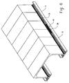
- FIG. 1 is a perspective view of a bridge system
- FIG. 2 is a perspective view of FIG. 1 with bridge units shown as transparent;
- FIGS. 3 a and 3 b are end views of embodiments of a foundation unit per FIG. 1 ;
- FIG. 4 is an end view of another embodiment of a foundation unit per FIG. 1 ;
- FIG. 5 is an enlarged partial perspective of FIG. 1 ;
- FIGS. 6 and 7 are perspective views of alternative bridge system shapes
- FIG. 8 shows the bridge system of FIG. 1 with wing walls
- FIGS. 9-10 show aspects of a wingwall foundation
- FIGS. 12 and 13 depict an alternative arrangement for supports of a foundation unit
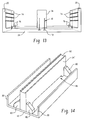
- FIGS. 14-18 show aspects of an embodiment in which the foundation structure includes a pedestal
- FIGS. 19 and 20 show wing wall anchors
- FIGS. 21 and 22 show a bridge system using metal plate
- FIG. 23 shows a partial view of a bridge system utilizing a composite bridge structure
- FIGS. 24 and 25 show a foundation structure formed unitary with a bridge unit
- FIGS. 26-31 show another embodiment of a foundation structure
- FIG. 32 shows a variation of the foundation structure of FIGS. 26-31 in combination with a pedestal unit
- FIGS. 33-35 show another embodiment of a bridge system and associated foundation structure
- FIGS. 36-38 show alternative embodiments of supports of precast concrete foundation units
- FIGS. 39-41 show another embodiment of a pedestal arrangement
- FIGS. 42-45 show another embodiment of a precast concrete foundation unit
- FIGS. 46-49 show a full span embodiment of a precast concrete foundation unit and system.
- a bridge structure 10 is shown atop spaced apart foundation structures 12 that, when completed, are made up of both precast and cast-in-place concrete.
- bridge structure 10 is formed by a plurality of side-by-side three sided precast bridge units 14 .
- Each foundation structure 12 is formed by a number of precast concrete foundation units 16 laid end to end (e.g., ends abutting each other).
- a length L of each precast foundation unit 16 accommodates three bridge units 14 , but many variations are possible.
- Each foundation unit includes a lower base portion 18 (e.g., as a bottom wall of the unit) with respective upright walls 20 extending upwardly at each side to define a generally U-shaped channel 22 .
- a central region of the channel 22 includes a series of upwardly extending, spaced apart supports 24 upon which the bottom ends of the side walls of the bridge units 14 are supported, either directly or indirectly.
- the bottom ends may sit on the surface of the support, in other implementations the bottom ends may sit on shims or a bracket or other channel member that is mounted on the support.
- the spacing between the supports 24 may vary, but should be no greater than the depth D B of the bridge units to be supported thereon.
- Supports may be located at each end of the foundation unit 16 so that end supports 24 of abutted units 16 will abut with each other as shown, but variations are possible.
- FIGS. 3 and 4 show exemplary end elevation views of alternative embodiments of the foundation units 16 .
- the end elevation profile is generally an E-shape with the legs of the E extending upward.
- the base 18 , walls 20 and supports 24 are formed as a unitary casting with suitable steel reinforcement 26 embedded therein.
- supports 24 could be cast as separate pieces and then attached to the base 18 either after the base 18 and walls 20 have been cast together, or during the casting process for the base 18 and walls 20 (e.g., by placement of the support 24 within the form in which the base 18 and walls are cast).
- one of the base 18 or walls 20 could be cast first and the other of the base or walls then cast in a manner to form the integrated base and wall unit.
- the walls 20 of the foundation unit 16 may be formed with inner sides 28 slightly angled (relative to vertical) such that the width W C1 of the channel 22 is greater at the top of the unit than the width W C2 of the channel 22 at the base 18 of the unit.
- This configuration provides the advantage of more easily removing the unit from the precast formwork and reducing the weight of the unit.
- the upper surface 30 of the base 18 may be formed with channels 32 to aid in binding with cast-in-place concrete that will be placed in the channel 22 on-site as will be described in further detail below.
- the vertical walls of the supports 24 may be formed (e.g., during the precasting) with horizontally extending pockets 34 configured to receive reinforcement 36 that will be manually placed in the field prior to pouring concrete. A portion of the reinforcement is received in the pocket 34 and a portion of the reinforcement protrudes from the pocket 34 . It is contemplated that the reinforcement 36 will extend lengthwise along substantially the full length of the foundation 12 formed by multiple foundation units 16 . It is also recognized that these pockets and longitudinal reinforcement could be incorporated into a surface of the end support 24 or one of the side walls 20 .
- field placed reinforcement 38 is provided on each side of the support members 24 .
- the reinforcement 38 is used to better tie the ends of adjacent foundation units 16 together with cast-in-place concrete and therefore such reinforcement may be limited to the vicinity of such end to end abutments 40 of the foundation units 16 as suggested in FIG. 5 .
- additional field placed reinforcement could be used in some applications.
- the width, length and height of the foundation units 16 may vary depending upon various aspects of the bridge installation.
- a rise of about 6-8′ feet and a depth of about 8′ the dimensions T 20-1 , T 20 -2, T B , W B and H (see FIG. 3 a ) could be on the order of about 4′′, 5′′, 6′′, 48′′ and 24′′ respectively;
- a rise of about 6-8′ feet and a depth of about 8′ the dimensions T 20-1 , T 20 -2, T B , W B and H (see FIG.
- the thickness of the supports 24 may typically be the same as or greater than the thickness of the bottom ends of the bridge unit that will rest thereon.
- the vertical dimension of supports 24 will adjust based on the overall precast foundation dimension.
- the horizontal location of support 24 may change within the U-shaped channel, such that in some implementations the supports 24 are centered or substantially centered along the width of the U-shaped channel, while in other implementations the support is offset (either toward the outer side wall of the unit or toward the inner side wall of the unit) partially or entirely from the center of the U-shaped channel.
- FIGS. 1 and 2 contemplate a three-sided bridge structure with straight side walls and a curved top wall
- the foundation system of the present application could be used in combination with other bridge unit configurations, including three-sided units with straight side walls and a straight top wall ( FIG. 6 ) or more traditional arch structures in which substantially the entire bridge unit is curved ( FIG. 7 ).
- the precast foundation units 16 of the present application facilitate the provision of a foundation with advantageous features.
- the precast foundation units are shipped to and received at a construction site.
- a final use/installation site is prepared to receive the precast foundation units by excavating to the desired elevation in a smaller area than traditional methods and preparing a level subsurface which may include additional backfill materials on which to install the units.
- the units are placed in end to end abutting relationship to form two spaced apart foundation structures 12 .
- the foundation units 16 are simply placed end to end without any structure holding the units adjacent each other.
- alignable bolt pockets may be formed at the end portions of the foundation units (e.g., in side walls 20 , base 18 and/or supports 24 ) and the bolts manually placed prior to setting of the bridge units.
- the bridge units 16 may be formed with lengthwise extending ducts could be formed in the foundation units so that tensioning members can be passed through the full length of the series of foundation units to secured them in abutting relationship.
- there may be other precast components to the foundation structure as well e.g., to support wing walls at the ends of the bridge structure).
- the reinforcement 36 and 38 can be manually placed and the bridge units placed atop the support structures 24 .
- the upper surface 42 of each support unit 24 may be positioned below the upper surfaces 44 of the side walls 20 .
- the bottom of the bridge unit side walls may rest directly atop the upper surface 42 of the support unit and/or shims 49 may be provided as needed for proper alignment and positioning of the bridge units 14 .
- additional tie in and/or alignment structure may be provided between the supports 24 and the bridge units, such as tie rods 43 ( FIG.
- the ties rods 43 may be precast into the foundation units 16 or threaded into surface accessible connectors at the end of reinforcement sections that are cast and embedded into the precast foundation unit.
- the cast-in-place concrete may typically be poured to the top of the channel (as represented by dashed line 46 in FIG. 4 ) or just below the top of the channel, in either case sufficiently high to embed and capture the bottom ends of each bridge unit so as to integrate the bridge units with the foundation. Preferably, at least about 2 to 3 inches of the bottom ends are embedded in the cast-in-place concrete. It is noted that the cast in place concrete can be applied along the outer portion of the U-shaped channel (i.e., the portion that is external of the bridge units) and the spacing between the supports 24 will allow the concrete to freely flow into and fill the other inner portion of the U-shaped channel as well as the portions aligned and between the supports 24 .
- an elongated support with one or more transverse bottom openings or channels could be used, such channels providing the route for concrete to flow from the outer portion of the U-shaped channel to the inner portion of the U-shaped channel during the pour.
- the concrete may be poured in the U-shaped foundation prior to the spans being set in place.
- the base 18 of the foundation units may be formed with openings to allow some through passage of concrete which may assist self-leveling.
- a bridge installation may also include wingwalls 50 at each end of the pathway 52 under the bridge units 14 .
- the foundation structures 12 may be formed with wingwall support portions 54 extending angularly away from the pathway 52 .
- Each wingwall support portion 54 is formed by one or more precast concrete wingwall support units 56 that become integrated with the foundation units 16 .
- each precast wingwall support or foundation unit 56 may be formed in a trapezoidal shape, or other shape that has a bottom surface that is wider than the top surface. The top surface supports the bottom edge of the wingwall 50 and the bottom surface rests upon the prepared site surface.
- the trapezoidal shape reduces the volume of concrete needed.
- One end surface 58 of the unit 56 extends generally perpendicular to a longitudinal axis of the unit 56 , while the other end surface 60 extends at an non-right angle (substantially offset from 90 degrees) to the longitudinal axis to define the angle at which the unit 56 will extend away from the foundation unit 16 and pathway 52 .
- the wingwall foundation unit 56 which is precast with necessary reinforcement therein, may include pocket 62 at end 60 and into which reinforcement 64 is positioned prior to the on-site concrete pour.
- Reinforcement sections 64 include a first leg 66 extending axially along the length of the support unit 16 and a second leg 68 extending axially along the length of wingwall support unit 56 into the pocket 62 .
- a laterally spaced series of reinforcement bars may be placed at each side of the end support member 24 of the foundation unit 16 .
- integration of the units 56 with units 16 may be achieved without the pocket by integrating dowel bars or reinforcing bars into the end 60 of unit 56 during precasting such that either the dowel bars or reinforcing bars extend from the end of the unit or a connector (e.g., internally threaded) is presented at the end face of the unit 56 to which the threaded end of a reinforcement bar can be connected.
- a connector e.g., internally threaded
- These dowel bars may be pre-bent or subsequently bent, or the reinforcement subsequently connected to the connectors at the end face, to provide extending reinforcement portions in general alignment with the lengthwise axis of the precast foundation unit 16 as shown.
- the protruding ends of the dowel rods or reinforcement become embedded in the cast-in-place concrete of the U-shaped channel during the on-site pour.
- the dowel rods or reinforcement could pass through openings in the elongated side walls of the precast unit 16 in order to enter the channel.
- the wing walls 50 may include anchor members 51 that will become embedded within the surrounding earthen fill material to laterally support the walls.
- the supports 24 could be cast as separate pieces and then attached to the base 18 of units 16 either after the base 18 and walls 20 have been cast together, or during the casting process for the base 18 and walls 20 .
- the supports 24 are precast separate from base 18 and side walls 20 .
- the supports 24 are precast first with partially embedded tie bolts 70 (or button bars) having heads 72 extending therefrom.
- the supports are then hung into the form that creates the base 18 and walls 20 , such that during casting the bolt heads 72 become embedded in the base 18 to secure the supports 24 to the base.
- the vertical surfaces of the U-shaped channel may also be formed with V-shaped channels to aid in integration with the cast-in-place concrete that will be poured into the U-shaped channel.
- Transport cables 76 may also be embedded in the base 18 for lifting and placing the precast concrete foundation units 16 .
- a pedestal type foundation may be desired.
- the base 18 and side walls 20 are precast as an integrated piece.
- the pedal structure 24 ′, including end feet 80 is also precast as an integrated piece, with a U-shaped recess 82 in its top surface.
- the U-shaped member formed by base 18 and side walls 20 and the pedestal 24 ′ are then shipped to the job site as separate precast components.
- the U-shaped member is placed, then the pedestal 24 ′ is positioned within the channel, and an on-site pour of concrete 84 can be used to integrate the two components together.
- an on-site pour of concrete 84 can be used to integrate the two components together.
- the central extent of the pedestal may be formed with a raised, transverse bottom channel 86 to allow poured concrete to flow from one side of the pedestal to the other.
- the bridge units can then be placed upon the pedestal 24 ′ with bottom ends within the channel 82 , and a concrete grout 88 applied within the channel 82 as well to provide a level of integration between the foundation and the bridge units.
- the pedestal 24 ′ may be centered or substantially centered along the width of the U-shaped channel and in other implementations the pedestal 24 ′ may be offset toward the outer side wall or inner side wall of the precast foundation unit.
- FIGS. 17 and 18 depict a pedestal arrangement used in connection a bridge structure in which two sets of bridge units 14 are utilized in combination with three foundation structures 12 to form two pathways 52 .
- the pedestal 24 ′′ of the center foundation structure 12 is formed wider than the pedestals 24 ′ of the outer foundation structures to provide a wider upper channel 82 ′ capable of supporting the bottom ends of two bridge units 14 .
- FIGS. 21 and 22 show an implementation in which the foundation supports a structural metal plate arch structure 90 .
- the center supports 24 are raised above an expected pour level 46 of the cast-in-place concrete and include a channel 92 that receives a u-shaped angle iron 94 , both of which are angled/offset from vertical so as to be arranged to receive the bottom end portion 96 of the metal plate arch 90 .
- the angle iron 94 may be embedded in the channel 92 during precast.
- FIG. 23 illustrates an embodiment in which the foundation structures 12 are utilized to support a composite arch.
- each support 24 receives the lower end of a composite tube 100 .
- an on-site concrete pour is performed to embed the lower ends of the tubes in the concrete of the foundation structure.
- Corrugated decking can then be set over the composite tubes for support thereby, and the composite tubes filled with concrete (e.g., self-consolidating expansive concrete).
- a concrete layer could also be placed over the corrugated decking.
- FIGS. 24 and 25 depict an embodiment in which the foundation units 16 are formed unitary with the bridge unit 14 as a single precast unit.
- the on-site pour and associated reinforcement complete the foundation structure after the combination units have been placed.
- the precast foundation units 160 are formed with a ladder configuration in which spaced apart side walls 150 are interconnected by a series of cross-member supports 152 .
- the foundation unit 160 lacks any bottom wall, such that open areas 154 extend vertically from the top to bottom of the units in the locations between the cross-members 152 .
- Each cross-member support 152 includes an upper surface with a recess 156 for receiving the bottom end of the bridge units.
- the recesses 156 may be centered or offset laterally from a center point along the width of the foundation unit as shown. In some cases the recesses 156 will be positioned toward the inward side of the overall structure, but variations are possible.
- the spacing of the cross-member supports 152 preferably matches the depth of the bridge units, such that adjacent end faces of the side-by-side bridge units abut each other in the vicinity of the recesses 156 as shown in FIG. 29 where the bridge units 14 are shown in transparent wire form.
- Each cross-member support 152 also includes one or more larger through openings 158 for the purpose of weight reduction and allowing concrete to flow from one open area or cell 154 to the next.
- Each cross-member also includes multiple, smaller axially extending reinforcement openings 162 . In the illustrated embodiment, an upper row 164 and lower row 166 of horizontally spaced apart openings is shown, but variations are possible.
- Axially extending reinforcement rods may be extended through such openings prior to delivery of the foundation units 160 to the installation site, but could also be installed on-site if desired. These openings 162 are also used to tie foundation units 160 end to end for longer foundation structures, via reinforcement extending from one unit to the next that becomes embedded in cast-in-place concrete.
- the side walls 150 include reinforcement sections 168 that include a portion 170 extending vertically and a portion 172 extending laterally into the open cell areas 154 in the lower part of the foundation unit 160 .
- opposing portions 172 of the two side walls can then be tied together by a lateral reinforcement section.
- the subject foundation units 160 can, in one embodiment, be manufactured using a single pour technique to produce both side walls and cross-members.
- each side wall portion 150 with reinforcement 168 may be formed as separate pieces from respective pours. Once cured, the side wall portions are then arranged with the desired lateral spacing, and suitable formwork added between the side walls (and at the ends of the side walls) to produce the cross-member supports 152 from another pour.
- the reinforcement portions 172 also extend into and within the cross-members to tie the cross-members to the side walls.
- upper lateral reinforcement portions 174 can also be provided in the vicinity of the cross-members, as well as lateral reinforcement pieces 176 that tie opposing portions 172 and opposing portions 174 together.
- the precast foundation units 160 are delivered to the job site and installed on ground that has been prepared to receive the units (e.g., compacted earth or stone).
- the bridge units 14 are placed after the precast foundation units 160 are set.
- the cells 154 remain open and unfilled during placement of the bridge units 14 (with the exception of any reinforcement that may have been placed either prior to delivery of the units 160 to the job site or after delivery).
- shims may be used for leveling and proper alignment of bridge units 14 .
- the cells 154 may then be filled with an on-site concrete pour.
- the pour will typically be made to the upper surface level 180 of the foundation units 160 , resulting in capture and embedment of the bottom portion of the bridge unit side walls within the concrete.
- the bottom surface of the bridge unit side walls may be formed with suitable reinforcement extensions or reinforcement openings such that vertical reinforcement can extend from the bottom of the unit.
- the foundation unit 160 may also be used in combination with various features and aspects of the other foundation unit embodiments described above, including the wingwall foundation and/or pedestals.
- the precast foundation unit 160 is shown in combination with a precast pedestal unit 190 .
- the two units are formed separately and delivered to a job site.
- the precast foundation unit 160 is first placed and then the precast pedestal placed within the foundation unit.
- the foundation unit cross-members 152 include recesses 192 and the pedestal unit includes upwardly extending cut-outs or slots 194 that fit over the cross-members in the vicinity of the recesses 192 .
- Exemplary reinforcement 196 of the pedestal having both an embedded vertical portion and a protruding lateral portion is shown, it being understood that the reinforcement(s) would extend or be distributed along the axial length of the pedestal.
- an on-site concrete pour is then performed to produce a unitary structure.
- the central extent of the pedestal unit may be formed with a raised, transverse bottom channel to allow poured concrete to flow from one side of the pedestal to the other. Once cured, the system is ready to receive the bridge units.
- the pedestal 190 includes an upper recess to receive the bottom of the bridge units.
- FIGS. 33-35 another embodiment having precast foundation units 200 with a ladder configuration is shown.
- the units have spaced apart and elongated upright walls 202 and 204 forming a channel 205 between the walls and cross-member supports 206 extending transversely across the channel to connect the walls 202 and 204 .
- the foundation units 200 lacks any bottom wall, such that open areas or cells 208 extend vertically from the top to bottom of the units in the locations between the cross-members 206 .
- Each cross-member support 206 includes an upper surface with a recess 210 for receiving the bottom portion of one side of the bridge units 214 .
- the side wall portions of the bridge units 214 extend from their respective bottom portions upwardly away from the combination precast and cast-in-place concrete foundation structure and inward toward the other combination precast and cast-in-place concrete foundation structure at the opposite side of the bridge unit.
- the recesses 210 extends from within the channel 205 toward the inner upright wall member 204 , that is the upright wall member positioned closest to central axis 212 of the bridge system.
- the upright wall member 202 has a greater height than the upright wall member 204 .
- Each cross-member support 206 also includes one or more larger through openings 216 for the purpose of weight reduction and allowing concrete to flow from one open area or cell 208 to the next.
- Each cross-member support also includes multiple axially extending reinforcement openings 218 . In the illustrated embodiment, an upper row 220 and lower row 222 of horizontally spaced apart openings 218 is shown, but variations are possible. Axially extending reinforcement may be extended through such openings prior to delivery of the foundation units 200 to the installation site, but could also be installed on-site if desired.
- openings 218 are also used to tie foundation units 200 end to end for longer foundation structures.
- the ends of the foundation units 200 that are meant to abut an adjacent foundation unit may be substantially open between the upright wall members 202 and 204 such that the abutting ends create a continuous cell 224 in which cast-in-place concrete will be poured.
- the far ends of the end foundation units 200 in a string of abutting units may typically include an end-located cross-member 206 as shown.
- the walls 202 and 204 include reinforcement 226 that includes a portion 228 extending vertically and a portion 230 extending laterally into the open cell areas 208 in the lower part of the foundation unit 200 .
- reinforcement 226 that includes a portion 228 extending vertically and a portion 230 extending laterally into the open cell areas 208 in the lower part of the foundation unit 200 .
- opposing portions 230 of the two side walls can then be tied together by a lateral reinforcement section 232 .
- the subject foundation units 200 can manufactured in a manner similar to units 160 as described above, with cross-member supports 206 also including reinforcement similar to that of cross-member supports 152 .
- the precast foundation units 200 are delivered to the job site and installed on ground that has been prepared to receive the units (e.g., compacted earth or stone).
- the bridge units 214 are placed after the precast foundation units are set.
- the cells 208 remain open and unfilled during placement of the bridge units 214 (with the exception of any reinforcement that may have been placed either prior to delivery of the units 200 to the job site or after delivery). Shims may be used for leveling and proper alignment of bridge units 214 .
- the cells 208 may then be filled with an on-site concrete pour. The pour will typically be made to the upper surface level of the foundation units 200 . In this regard, and referring to FIG.
- the bottom portion 240 of the bridge unit will be captured and embedded within the cast-in-place concrete 242 at the outer side of bottom portion 240 .
- the cast-in-place concrete at the outer side of the bottom portion 240 of the bridge unit is higher than a bottom surface of the bottom portion 240 to embed the bottom portion at its outer side, and the cast-in-place concrete at the inner side of the bottom portion of the bridge unit is substantially flush with the bottom surface of the bottom portion 240 . In this manner, the flow area beneath the bridge units is not adversely impacted by embedment of the bottom portions 240 of the bridge units.
- the foundation unit 200 may also be used in combination with various features and aspects of the other foundation unit embodiments described above, including the wingwall foundation and/or pedestals.
- the precast foundation unit 200 may be used in combination with a pedestal structure.
- the foundation units 160 and 200 are both well adapted for use in connection with pile foundation systems. That is, the support piles can be driven into the ground at the intended use location of the unit (before or after placement of the unit) with the upper ends of the piles protruding into the open cell areas. When the on-site pour is carried out, the piles become embedded in the cast-in-place concrete, structurally tying the combination precast and cast-in-place foundation structure to the piles.
- the pedestal unit 250 includes a central bottom portion 254 that seats within the recesses 156 of the cross-member supports 152 , and integrated side supports 256 that rest on the upper surfaces of the cross-member supports 152 , and in the illustrated embodiment partly on the upper surfaces of the elongated upright sidewalls 150 , to provide lateral support to the pedestal.
- side supports 256 are provided only at the ends of the pedestal unit 250 , but the side supports could also be provided elsewhere along the length of the pedestal unit.
- cast-in-place concrete poured at the use location and within the cells 154 of the unit 160 embeds the bottom of the pedestal unit 250 and integrates the precast pedestal unit 250 with to precast foundation unit 160 to form an integrated foundation structure.
- reinforcement 260 having a part 262 extending within the pedestal unit 250 and a part 264 extending out of the bottom of the pedestal unit into the cast-in-place concrete aids in the integration.
- the cast-in-place concrete also ties the precast concrete foundation unit 160 to the piles 252 .
- precast concrete foundation units 16 , 160 and 200 have spaced apart elongated upright wall members to define a channel therebetween, and multiple upright supports located within the channel.
- the units In the illustrated embodiments of precast concrete foundation units 16 , the units have a bottom wall and the supports extend upward from the bottom wall. In the illustrated embodiments of foundation units 160 and 200 the units have no bottom wall and the supports extend between and connect the elongated upright wall members.
- the multiple supports of one precast concrete foundation unit when installed at the final use site should typically substantially align with the multiple supports of the another, substantially parallel precast concrete foundation unit (e.g., supporting the opposite side of the bridge structure).
- the elongated upright wall members may have the same height (e.g., as in the illustrated embodiments of units 16 and 160 ) or the elongated upright wall members may have different heights (e.g., as in the illustrated embodiment of unit 200 ).
- top recesses of the supports when present, may be located entirely within the channel of the unit (e.g., as in some of the illustrated embodiments of units 16 and in the illustrated embodiments of units 160 ), or the recesses may be extend from the channel to one of the elongated walls (e.g., as shown in the illustrated embodiment of units 200 ).
- supports of the precast foundation units may in some cases have recesses and in other cases not have recesses.
- other embodiments may utilize channel members that are mounted to the supports.
- FIGS. 36-38 embodiments of supports 24 , 152 , 206 having a channel member 250 a , 250 b , 250 c mounted thereon are shown, with the channel member receiving the bottom portion 260 a , 260 b , 260 c of a bridge unit.
- the channel member may be mounted to the support using any suitable attachment structure 252 a , 252 b , 252 c (e.g., bolt(s) or other anchor(s)).
- the channel member itself may be partly embedded in the precast concrete or may be secured by a construction adhesive.
- the channel member may take on various shapes (e.g., U-shaped, L-shaped or an irregular shape).
- the channel member may typically be of metal plate construction (e.g., U-channel or L-channel), but other materials may be used.
- the channel member acts to receive and support the bottom portion of the bridge units, in a similar manner to the recesses described above.
- Both the recesses and the channel members are examples of “receiving channels” for the bottom portions of the bridge units. Shims may be used in combination with receiving channels as well (e.g., between the receiving channel and the bottom surface of the bridge unit side).
- embedded reinforcement may typically be used to lock the wingwall foundation units 54 to the foundation units 16 , 160 , 200 to provide a rigid, integrated structure.
- Cast-in-place concrete provides at least part of the embedment of the reinforcement.
- the cast-in-place concrete embedment may be in the concrete poured in the channel of the foundation units 16 , 160 , 200 and in other examples the cast-in-place concrete embedment may be in an end channel of the wingwall foundation unit 56 .
- part of the reinforcement may be embedded in part of the precast concrete before the final embedment in the cast-in-place concrete is achieved.
- a first portion of the reinforcement is embedded in the precast concrete and has a surface exposed/accessible internally threaded socket end to which a second reinforcement portion is threadedly connected after curing of the concrete, such that, the first portion is embedded and the second portion initially protrudes.
- a continuous unitary piece of reinforcement has one part embedded in the precast concrete and one part protruding from the precast concrete.
- the combination precast and cast-in-place concrete foundation structures described herein can be utilized to support virtually any type bridge structure. Moreover, other types of structures could be supported as well. On-site time and expense associated with foundation placement is reduced (e.g., the need for form placement and much of the reinforcement placement is eliminated).
- FIGS. 42-45 another foundation unit embodiment is shown, with the lengthwise direction of the unit represented by axis 290 and the lateral direction of the unit represented by axis 292 .
- axis 290 the lengthwise direction of the unit represented by axis 290
- lateral direction of the unit represented by axis 292 a single foundation unit is depicted, it should be understood that multiple foundation units can and often would be laid end to end in the lengthwise direction and that a set of laterally spaced apart foundation units could be used to support opposite side walls of precast bridge units in the same manner described above.
- the precast foundation unit 300 includes a spaced apart elongated upright wall members 302 and 304 to define a channel 306 therebetween.
- Multiple upright supports 308 extend laterally across the channel and interconnect the elongated upright wall members 302 and 304 to define open cells 310 within the channel.
- the cells are open at both the top and bottom of the unit.
- the number of supports 308 and cells 310 could vary.
- one or more of the end portions of each unit 300 could be formed with open U-shaped channel portions (e.g., per FIG. 34 above) to facilitate end to end placement of units.
- An inner side 312 of elongated upright wall member 304 includes lengthwise recesses 314 and 316 facing each open cell 310 and an inner side 318 of the upright wall member 302 includes lengthwise recesses 320 and 322 (shown in dashed line form) facing each open cell 310 .
- recess 316 is positioned below recesses 314 and extends substantially parallel thereto.
- recess 322 is positioned below recess 320 and extends substantially parallel thereto.
- Recess 320 is positioned in opposed and aligned relationship with recess 314
- recess 322 is positioned in opposed and aligned relationship with recess 316 .
- the upright supports 308 each include a plurality of lengthwise extending through openings 324 for receiving reinforcement.
- a set 326 of six laterally spaced apart reinforcement openings 324 are located along an upper part of the support 308 and a set 328 of six laterally spaced apart openings 324 are located along a lower part of the support, but numerous variations of the number and position of reinforcement openings are possible.
- All or some of the supports 308 may also include a larger through opening 330 for the purpose of facilitating concrete flow from one cell to another as described above.
- the top of each of the supports also includes a recess 332 , which is used to receive the bottom portion 334 of a precast bridge unit to be supported on the foundation (e.g., per the embodiments previously described above).
- a precast concrete foundation unit 300 Utilizing a precast concrete foundation unit 300 as described, an advantageous method of constructing a combination precast and cast-in-place concrete foundation structure can be implemented. Specifically, subsequent to casting of the precast concrete foundation unit 300 , a plurality of elongated metal reinforcement members 340 are inserted into each open cell 310 such that each elongated metal reinforcement member 340 extends laterally between the opposed lengthwise recesses (e.g., 314 and 320 or 316 and 322 ). As best seen in FIG. 44 , one end of the elongated metal reinforcement member is positioned in one lengthwise recess and the opposite end of the elongated metal reinforcement member is positioned in the lengthwise recess on the other side of the open cell.
- the opposed lengthwise recesses e.g., 314 and 320 or 316 and 322
- a plurality of reinforcement members 340 A may be positioned in the upper region of the cell (e.g., extending between recesses 314 and 320 ) and a plurality of reinforcement members 340 B may be positioned in the lower region of the cell (e.g., between recesses 316 and 322 ).
- a plurality of elongated metal reinforcement members 342 are inserted through the lengthwise extending through openings 324 such that each elongated metal reinforcement member extends lengthwise along the precast concrete foundation unit 300 .
- a multiplicity of reinforcement members 342 A may be positioned in the upper region of the cell (e.g., by insertion through opening set 326 ) and a multiplicity of reinforcement members 342 B may be positioned in the lower region of the cell (e.g., by insertion through opening set 328 ).
- each elongated metal reinforcement member 340 may be tied (e.g., using concrete ties 344 ) to at least one elongated metal reinforcement member 342 (and visa versa) to maintain a desired position of each elongated metal reinforcement member 340 within its cell.
- the height of opening set 326 is proximate the height of lengthwise recesses 314 and 320
- the height of opening set 328 is proximate the height of lengthwise recesses 316 and 322 . Regardless of when the lengthwise and lateral reinforcement is inserted, the reinforcement is not embedded within the precast concrete of the unit 300 .
- the precast concrete foundation unit 300 is placed at a desired use location of the construction site, and then concrete is delivered into the open cells 310 while the precast concrete foundation unit remains at the desired use location.
- the concrete is allowed to cure-in-place within the cells such that the elongated metal reinforcement members 340 and the elongated reinforcement members 342 become embedded in the cured-in-place concrete (e.g., per FIG. 45 which shows en elevation view of a cell with cast-in-place concrete therein, that also embeds the bottom portion 334 of a bridge unit in the recess 332 ).
- a lateral distance between the opposed lengthwise recesses in each cell may be less than a lengthwise distance between the upright supports at opposite ends of each cell.
- the step of inserting the lateral metal reinforcement members involves orienting each of the elongated metal reinforcement members at an angle that is offset from perpendicular to the lengthwise axis 290 of the precast concrete foundation unit, moving the elongated metal reinforcement member into the cell to a depth aligned with a pair of the opposed lengthwise recesses (e.g., either ecesses 314 and 320 or recesses 316 and 322 ) and then rotating the elongated metal reinforcement such that one end moves in one lengthwise recess and the opposite end moves into the other lengthwise recess.
- a pair of the opposed lengthwise recesses e.g., either ecesses 314 and 320 or recesses 316 and 322
- one or more vertical recesses that intersect with the lengthwise recesses may be provided (e.g., per 350 shown in dashed line form in FIG. 42 ).
- the step of inserting the elongated metal reinforcement members involves orienting each of the elongated metal reinforcement members such that one end is aligned with a vertical recess of one wall 302 and the opposite end is aligned with the vertical recess of the other wall 304 , and moving the elongated metal reinforcement member depthwise along the vertical recesses until the ends are positioned in the respective lengthwise recesses, at which point the reinforcement member can be shifted in the lengthwise direction of the foundation unit to a desired position along the lengthwise recesses.
- foundation unit 300 also enables an advantageous construction operation that is adaptable to specific needs of a given project.
- the method involves identifying a lay length of each of multiple precast concrete bridge units to be placed atop the precast concrete foundation unit when installed.
- the lay length is the dimension of the bridge unit in the lengthwise direction of the precast concrete foundation unit, also referred to above as the depth of the bridge unit (shown as D B in FIG. 1 ).
- the precast concrete foundation unit is manufactured such that a center to center distance between the upright supports on opposite ends of each cell (e.g., distance L C ) corresponds to the identified lay length. In this manner, each support can be used to support two adjacent precast bridge units that abut each other atop the support.
- each of the multiple supports 308 of the precast foundation unit 300 has a bottom surface 360 that is coextensive (entirely, or at least partially) with the bottom surfaces 362 , 364 of the elongated walls 302 and 304 .
- This arrangement assures that when the foundation unit 300 is placed on the ground at an installation location, the supports 308 will also be in contact with the ground (e.g., per FIG. 44 ).
- bridge units or another structure
- the supports 308 are interconnected with the elongated walls 302 and 304 by embedded reinforcement 370 and 372 (e.g., similar to that described above).
- embedded reinforcement 370 and 372 e.g., similar to that described above.
- Another benefit to having a bottom surface portion 360 of supports 308 in the same plane as bottom surfaces 362 and 364 is that the overall foundation unit to ground surface area contact is enhanced, reducing the likelihood, or at least the degree, that the foundation unit may be pushed into the ground under loaded conditions that occur before the on-site concrete pour into the cells.
- the precast foundation units 400 are constructed with a width that extends the full span of the precast bridge units 402 to be supported thereon.
- foundation units 400 may be of a type 400 a with or a type 400 b .
- Foundation units 400 a include elongated upright wall members 404 and 406 spaced apart to define a channel 408 therebetween, and multiple upright supports 410 extending laterally across the channel 408 and interconnecting the upright wall members.
- Foundation unit 400 b which is generally I-shaped in top plan view, includes elongated upright wall members 412 and 414 spaced apart to define a channel 416 therebetween, and a single upright support 418 extending laterally across the channel 416 and interconnecting the upright wall members. It is recognized that more than one foundation unit 400 b could be interposed between end foundation units 400 a . It is further recognized that all foundation units of a given installation could be of a type with multiple lateral supports (e.g., 2 or more). Each lateral support 410 , 418 has end portions that are recessed slightly relative to its adjacent upright wall member to define bridge unit support surfaces 420 , 422 upon which the bottom ends of the precast bridge units are placed.
- the recessed surface portions 420 , 422 could be eliminated in favor of surface 425 extending all the way from the inner side of wall 440 to the inner side of wall 406 .
- the lengthwise axis 450 of the foundation units and foundation system is also shown.
- FIG. 48 shows an exemplary elevation view of a typical lateral support member 410 or 418 of the foundation units.
- the lateral support includes internal reinforcement 424 extending through the support and linked with internal reinforcement (e.g., U-shaped) of the upright walls.
- the upright lateral supports also include a plurality of through openings 428 for receiving reinforcement.
- a set of laterally spaced apart reinforcement openings 428 are located along a lower part of the supports, and a pair of laterally spaced reinforcement openings 428 are located at an upper part of the support near each end of the support, but numerous variations of the number and position of reinforcement openings are possible.
- All or some of the supports may also include one or more larger through openings 430 for the purpose of facilitating concrete flow from one cell to another as described above.
- an inner side 432 of upright wall member 404 includes lengthwise recesses 434 and 436 facing the channel 408
- the inner side 438 of upright wall member 406 includes similar lengthwise recesses 440 and 44 , with recess 440 having a height aligned with that of recess 434 , and recess 442 having a height aligned with that of recess 436 .
- the recesses 434 , 436 and 440 , 442 can be used, in combination with the openings 428 , for holding reinforcement that will become encased in cast-in-place concrete as the site of installation, in a manner similar to that described above with respect to FIGS. 42-45 .
- the channel of the foundation units is filled with cast-in-place concrete after the foundation units have been placed at the final installation location of the bridge unit or other structure to be supported.
- the cast-in-place concrete is delivered to a height 452 that just matches the bottom of the bridge units, but in another embodiment the cast-in-place concrete may be delivered to a slightly higher level 454 so as to partially embed the lower ends of the bridge units therein.
- the bridge units may be placed upon the foundation before or after pouring of the concrete, while in the latter embodiment the bridge units must be placed before final pouring the level 454 .
- FIGS. 46-49 is a full span foundation system in which the distance between the upright wall members of the foundation units is slightly greater than the span of the bridge units that will be place upon the foundation. It is recognized that such full span foundation units could be incorporated into one or more of the previously described embodiments as well.
Landscapes
- Engineering & Computer Science (AREA)
- Civil Engineering (AREA)
- Structural Engineering (AREA)
- Life Sciences & Earth Sciences (AREA)
- General Life Sciences & Earth Sciences (AREA)
- Mining & Mineral Resources (AREA)
- Paleontology (AREA)
- General Engineering & Computer Science (AREA)
- Architecture (AREA)
- Environmental & Geological Engineering (AREA)
- Bridges Or Land Bridges (AREA)
Abstract
Description
Claims (18)
Priority Applications (10)
| Application Number | Priority Date | Filing Date | Title |
|---|---|---|---|
| US14/098,615 US8925282B2 (en) | 2011-07-08 | 2013-12-06 | Foundation system for bridges and other structures |
| PCT/US2013/074129 WO2014093344A1 (en) | 2012-12-13 | 2013-12-10 | Foundation system for bridges and other structures |
| EP13862489.5A EP2931976B1 (en) | 2012-12-13 | 2013-12-10 | Foundation system for bridges and other structures |
| PL13862489.5T PL2931976T3 (en) | 2012-12-13 | 2013-12-10 | Foundation system for bridges and other structures |
| NZ708317A NZ708317A (en) | 2012-12-13 | 2013-12-10 | Foundation system for bridges and other structures |
| AU2013359540A AU2013359540B2 (en) | 2012-12-13 | 2013-12-10 | Foundation system for bridges and other structures |
| CA2891941A CA2891941C (en) | 2012-12-13 | 2013-12-10 | Foundation system for bridges and other structures |
| US14/647,233 US9695558B2 (en) | 2012-12-13 | 2013-12-10 | Foundation system for bridges and other structures |
| CR20150285A CR20150285A (en) | 2012-12-13 | 2015-05-28 | FOUNDATION SYSTEM FOR BRIDGES AND OTHER STRUCTURES |
| US15/595,376 US20170247843A1 (en) | 2012-12-13 | 2017-05-15 | Foundation system for bridges and other structures |
Applications Claiming Priority (6)
| Application Number | Priority Date | Filing Date | Title |
|---|---|---|---|
| US201161505564P | 2011-07-08 | 2011-07-08 | |
| US201261637922P | 2012-04-25 | 2012-04-25 | |
| US13/541,043 US8789337B2 (en) | 2011-07-08 | 2012-07-03 | Foundation system for bridges and other structures |
| US201261736819P | 2012-12-13 | 2012-12-13 | |
| US201361837853P | 2013-06-21 | 2013-06-21 | |
| US14/098,615 US8925282B2 (en) | 2011-07-08 | 2013-12-06 | Foundation system for bridges and other structures |
Related Parent Applications (1)
| Application Number | Title | Priority Date | Filing Date |
|---|---|---|---|
| US13/541,043 Continuation-In-Part US8789337B2 (en) | 2011-07-08 | 2012-07-03 | Foundation system for bridges and other structures |
Related Child Applications (3)
| Application Number | Title | Priority Date | Filing Date |
|---|---|---|---|
| PCT/US2013/074129 Continuation WO2014093344A1 (en) | 2012-12-13 | 2013-12-10 | Foundation system for bridges and other structures |
| US14/647,233 Continuation US9695558B2 (en) | 2012-12-13 | 2013-12-10 | Foundation system for bridges and other structures |
| US14/647,233 Continuation-In-Part US9695558B2 (en) | 2012-12-13 | 2013-12-10 | Foundation system for bridges and other structures |
Publications (2)
| Publication Number | Publication Date |
|---|---|
| US20140090191A1 US20140090191A1 (en) | 2014-04-03 |
| US8925282B2 true US8925282B2 (en) | 2015-01-06 |
Family
ID=50383854
Family Applications (1)
| Application Number | Title | Priority Date | Filing Date |
|---|---|---|---|
| US14/098,615 Active US8925282B2 (en) | 2011-07-08 | 2013-12-06 | Foundation system for bridges and other structures |
Country Status (1)
| Country | Link |
|---|---|
| US (1) | US8925282B2 (en) |
Cited By (6)
| Publication number | Priority date | Publication date | Assignee | Title |
|---|---|---|---|---|
| US9695558B2 (en) | 2012-12-13 | 2017-07-04 | Contech Engineered Solutions LLC | Foundation system for bridges and other structures |
| US10011962B2 (en) * | 2014-05-02 | 2018-07-03 | Soletanche Freyssinet S.A.S. | Method of enlarging the space beneath a masonry arch bridge, and a masonry arch bridge |
| US10267011B2 (en) * | 2015-01-23 | 2019-04-23 | Eco Concrete Solutions, Inc. | Pre-cast decorative retaining wall system |
| US11174614B2 (en) | 2017-08-14 | 2021-11-16 | Contech Engineered Solutions LLC | Metal foundation system for culverts, buried bridges and other structures |
| US11536017B2 (en) * | 2016-10-26 | 2022-12-27 | Envirokeeper, LLC | Modular precast concrete water storage device and system |
| USD1045128S1 (en) * | 2021-07-13 | 2024-10-01 | William Daniel Ochse | Modular concourse |
Families Citing this family (8)
| Publication number | Priority date | Publication date | Assignee | Title |
|---|---|---|---|---|
| US20140270990A1 (en) * | 2013-03-15 | 2014-09-18 | Utility Concrete Products, Llc | Precast concrete retaining wall |
| EP3237726B1 (en) * | 2014-12-22 | 2023-08-09 | James Crawford Thomson | Method and apparatus for forming tunnels for transport routes |
| CN104911988A (en) * | 2015-06-09 | 2015-09-16 | 中交第二公路勘察设计研究院有限公司 | Prefabricated reinforced concrete embedded type upright frame bridge |
| CN105019474B (en) * | 2015-07-29 | 2017-09-26 | 上海市政工程设计研究总院(集团)有限公司 | A kind of genuine reconstruction structure and its reconstruction method |
| CN107842032B (en) * | 2017-12-20 | 2023-06-23 | 广西大学 | Large-span arch bridge foundation |
| CN113699895B (en) * | 2021-09-29 | 2022-07-01 | 西安建筑科技大学 | Construction method for overhead jacking of frame-structured bridge into existing line of multiple tracks |
| CN114703735B (en) * | 2022-04-14 | 2023-09-19 | 北京市市政工程设计研究总院有限公司 | Multi-span upper bearing type continuous arch bridge vault structure |
| USD1134700S1 (en) * | 2025-04-06 | 2026-07-14 | Cur-Tech, LLC | Cap for forming access opening to chamber |
Citations (75)
| Publication number | Priority date | Publication date | Assignee | Title |
|---|---|---|---|---|
| US109886A (en) | 1870-12-06 | Bitehieddec | ||
| US567653A (en) | 1896-09-15 | William sink paekee | ||
| US1074268A (en) | 1912-03-29 | 1913-09-30 | Charles D Kelly | Concrete arch. |
| US1184634A (en) | 1915-05-10 | 1916-05-23 | Paul B Lehrkind | Culvert. |
| US1412615A (en) | 1921-03-18 | 1922-04-11 | Ernest W Johnson | Agricultural implement |
| US1474808A (en) | 1920-02-24 | 1923-11-20 | Zucco Pierre | Method of tunnel construction |
| US1784271A (en) | 1927-07-13 | 1930-12-09 | Pacific Clay Products | Conduit and method of constructing the same |
| US2616149A (en) | 1941-01-09 | 1952-11-04 | Bowen Colthurst & Partners Ltd | Method of molding in situ concrete arched structures |
| US3195852A (en) | 1963-07-17 | 1965-07-20 | Lundell Mfg Company | Concrete form structure |
| US3286972A (en) | 1964-06-19 | 1966-11-22 | James H Jackson | Device for suspending forms from structural beams |
| US3397494A (en) | 1966-04-04 | 1968-08-20 | Reynolds Metals Co | Building apparatus and method of making same |
| US3848377A (en) | 1973-02-09 | 1974-11-19 | M Mori | Mat foundation |
| FR2330818A1 (en) | 1975-11-05 | 1977-06-03 | Squecco Jules | Reinforced concrete building foundation section - in shape of inverted U, with hook on top and ridge on which wall is built |
| US4094110A (en) | 1976-03-24 | 1978-06-13 | Radva Plastics Corporation | Building system and method |
| US4099360A (en) | 1975-05-13 | 1978-07-11 | Ccl Systems, Ltd. | Method and device for joining concrete bodies and method of constructing a multi-story building |
| US4141666A (en) | 1978-02-16 | 1979-02-27 | Kaiser Aluminum & Chemical Corporation | Low headroom culvert |
| US4211504A (en) | 1976-06-24 | 1980-07-08 | Sivachenko Eugene W | High strength corrugated metal plate and method of fabricating same |
| US4318635A (en) | 1980-07-07 | 1982-03-09 | Bethlehem Steel Corporation | Culvert structure having corrugated ribbing support |
| US4558969A (en) | 1984-03-19 | 1985-12-17 | Bebo Of America | Hinge for use with large pre-cast overfilled load support structures |
| US4563107A (en) | 1981-06-17 | 1986-01-07 | Nova Span International Ltd. | Arch beam structure |
| US4587684A (en) | 1983-10-14 | 1986-05-13 | Roman Arch And Culvert Corporation Of America | Precast concrete bridge |
| US4687371A (en) | 1983-12-28 | 1987-08-18 | Con/Span Culvert Systems, Inc. | Precast concrete culvert section |
| US4693634A (en) | 1984-06-05 | 1987-09-15 | Tensiter S.P.A. | Prefabricated support and covering structure, particularly for constructing tunnels, bridges and the like |
| EP0244890A2 (en) | 1981-11-17 | 1987-11-11 | Marcel Matière | Process for producing hollow structures such as ducts, silos, or shelters, and structures obtained by this process |
| US4723871A (en) | 1987-05-11 | 1988-02-09 | Duane Roscoe | Inexpensive headwall for culverts |
| US4797030A (en) | 1983-12-28 | 1989-01-10 | Con/Span Culvert Systems, Inc. | Precast concrete culvert system |
| US4817353A (en) | 1987-10-28 | 1989-04-04 | Woods John T | Selfcontained integral footing form and foundation wall |
| US4972641A (en) | 1989-09-27 | 1990-11-27 | Modern Industries, Inc. | Leave-in-place cantilever concrete foundation form |
| US4972646A (en) | 1988-03-14 | 1990-11-27 | Foam Form Systems, Inc. | Concrete forming system |
| US4987707A (en) | 1988-01-27 | 1991-01-29 | Kiselev Vasily P | Vaulted building structure |
| US4993872A (en) | 1983-12-28 | 1991-02-19 | Con/Span Culvert Systems, Inc. | Precast concrete culvert system |
| WO1992007144A1 (en) | 1990-10-19 | 1992-04-30 | Societe Des Prefabriques En Beton Et Materiaux Pour L'agriculture Et La Construction | Process for building structural works comprising an arch and prefabricated parts for carrying out said process |
| US5252002A (en) | 1992-07-14 | 1993-10-12 | Day Jesse C | Natural bottom culvert and method for installation |
| EP0568799A1 (en) | 1992-05-07 | 1993-11-10 | Peca-Verbundtechnik Gmbh | Shuttering for a joint |
| US5326191A (en) | 1993-03-04 | 1994-07-05 | Michael M. Wilson | Reinforced metal box culvert |
| US5505033A (en) | 1988-12-06 | 1996-04-09 | 501 Hitachi Metals Ltd. | Column base structure and connection arrangement |
| US5524405A (en) | 1994-02-28 | 1996-06-11 | Byrd; Randall | Wall structure |
| US5533835A (en) | 1995-02-06 | 1996-07-09 | Angelette; A. M. | Railroad crossing signal foundation and method of producing and erecting the same |
| US5536113A (en) | 1994-05-16 | 1996-07-16 | North Star Concrete Of Ohio, Inc. | Precast concrete wingwall |
| US5586417A (en) | 1994-11-23 | 1996-12-24 | Henderson; Allan P. | Tensionless pier foundation |
| US5720577A (en) | 1995-10-11 | 1998-02-24 | Contech Constructions Products Inc. | Box culvert |
| US5836717A (en) | 1997-02-25 | 1998-11-17 | Bebo Of America | Multi-segment spandrel wall for overfilled arch structures |
| USD406902S (en) | 1997-07-28 | 1999-03-16 | Con/Span Bridge Systems, Inc. | Concrete bridge section |
| USD426321S (en) | 1998-12-09 | 2000-06-06 | Con/Span Bridge Systems, Inc. | Composite bridge deck pultrusion |
| US6094881A (en) | 1998-04-30 | 2000-08-01 | Con/Span Bridge Systems Inc. | Box shaped structural member with pultruded flanges and connecting webs |
| US6161342A (en) | 1996-07-24 | 2000-12-19 | Samflo | Prefabricated concrete element for building a civil engineering structure having an arched wall |
| US6205717B1 (en) | 2000-04-11 | 2001-03-27 | Freyssinet International (Stup) | Bunker construction |
| US6243994B1 (en) | 1999-01-11 | 2001-06-12 | Bebo Of America, Inc. | Joint for pre-cast concrete twin-leaf arch sections |
| US6367214B1 (en) | 1996-07-17 | 2002-04-09 | Mosé Monachino | Foundation element, methods for the construction of prefabricated structures including these elements, particularly prefabricated tunnels, and prefabricated structures made by these methods |
| US6474907B2 (en) | 2000-12-13 | 2002-11-05 | Robert A. Semotiuk | Environmentally compatible archway for road building |
| US6640505B1 (en) | 2001-10-25 | 2003-11-04 | Bebotech Corporation | Hybrid arched overfilled structure |
| USD484610S1 (en) | 2003-02-12 | 2003-12-30 | Con/Span Bridge Systems Ltd. | Concrete tunnel for a rapid transit train |
| US6719492B1 (en) | 2002-03-22 | 2004-04-13 | Bebotech Corporation | Top arch overfilled system |
| USD490533S1 (en) | 2003-01-24 | 2004-05-25 | Con/Span Bridge Systems Ltd. | Concrete tunnel for a rapid transit train |
| US6854928B2 (en) | 2002-01-30 | 2005-02-15 | Con/Span Bridge Systems Ltd. | Precast concrete culvert system |
| US20050123354A1 (en) | 2003-12-03 | 2005-06-09 | Con/Span Bridge Systems Ltd. | Method for improving the environment within soil embedded culvert and bridge systems |
| USD511215S1 (en) | 2004-11-19 | 2005-11-01 | Con/Span Bridge Systems Ltd. | Precast concrete bridge unit |
| USD511387S1 (en) | 2004-03-01 | 2005-11-08 | Con/Span Bridge Systems Ltd. | Concrete bridge unit with integral footers |
| USD512513S1 (en) | 2004-09-15 | 2005-12-06 | Con/Span Bridge Systems Ltd. | Concrete bridge and headwall unit |
| US6988337B1 (en) | 2002-03-22 | 2006-01-24 | Bebotech Corporation | Means and method for constructing a fully precast top arch overfilled system |
| USD514706S1 (en) | 2004-03-01 | 2006-02-07 | Con/Span Bridge Systems Ltd. | Concrete bridge and headwall unit |
| US7001110B2 (en) | 2004-03-01 | 2006-02-21 | Con/Span Bridge Systems Ltd. | Precast concrete retaining wall |
| US7217064B1 (en) | 2005-12-23 | 2007-05-15 | Wilson Michael W | Reinforcement of arch type structure with beveled/skewed ends |
| US20070261341A1 (en) | 2005-03-08 | 2007-11-15 | Contech Bridge Solutions, Inc. | Open bottom fiber reinforced precast concrete arch unit |
| US7305798B1 (en) | 2002-04-25 | 2007-12-11 | Bebo Of America | Composite overfilled arch system |
| US20080006003A1 (en) | 2004-02-12 | 2008-01-10 | Milovan Skendzic | Method of Constructing Strip Foundations with Longitudinal Socket |
| USD566852S1 (en) | 2006-07-21 | 2008-04-15 | Ivan Gaster | Molded plastic arch unit for a culvert or bridge |
| USD573722S1 (en) | 2007-03-28 | 2008-07-22 | Contech Bridge Solutions Inc. | Precast concrete support for a bridge |
| US7556451B2 (en) | 2005-09-09 | 2009-07-07 | Contech Bridge Solutions Inc. | Precast concrete bridge and headwall assembly and method of production |
| US7568860B2 (en) | 2003-07-08 | 2009-08-04 | Carlo Chiaves | System for articulably bearing a prefabricated structural member on a foundation |
| US7770250B2 (en) | 2008-01-22 | 2010-08-10 | County Materials Corporation | Flared leg precast concrete bridge system |
| USD645572S1 (en) | 2010-11-15 | 2011-09-20 | Von Handorf Jeffrey J | Precast concrete bridge unit |
| USD658976S1 (en) | 2011-09-01 | 2012-05-08 | Morrow Jr Sidney Owen | Roof safety anchor |
| US20130008108A1 (en) | 2011-07-08 | 2013-01-10 | Aston Scott D | Foundation system for bridges and other structures |
| US8523486B2 (en) | 2012-02-06 | 2013-09-03 | Contech Engineering Solutions LLC | Concrete culvert assembly and related methods |
-
2013
- 2013-12-06 US US14/098,615 patent/US8925282B2/en active Active
Patent Citations (81)
| Publication number | Priority date | Publication date | Assignee | Title |
|---|---|---|---|---|
| US109886A (en) | 1870-12-06 | Bitehieddec | ||
| US567653A (en) | 1896-09-15 | William sink paekee | ||
| US1074268A (en) | 1912-03-29 | 1913-09-30 | Charles D Kelly | Concrete arch. |
| US1184634A (en) | 1915-05-10 | 1916-05-23 | Paul B Lehrkind | Culvert. |
| US1474808A (en) | 1920-02-24 | 1923-11-20 | Zucco Pierre | Method of tunnel construction |
| US1412615A (en) | 1921-03-18 | 1922-04-11 | Ernest W Johnson | Agricultural implement |
| US1784271A (en) | 1927-07-13 | 1930-12-09 | Pacific Clay Products | Conduit and method of constructing the same |
| US2616149A (en) | 1941-01-09 | 1952-11-04 | Bowen Colthurst & Partners Ltd | Method of molding in situ concrete arched structures |
| US3195852A (en) | 1963-07-17 | 1965-07-20 | Lundell Mfg Company | Concrete form structure |
| US3286972A (en) | 1964-06-19 | 1966-11-22 | James H Jackson | Device for suspending forms from structural beams |
| US3397494A (en) | 1966-04-04 | 1968-08-20 | Reynolds Metals Co | Building apparatus and method of making same |
| US3848377A (en) | 1973-02-09 | 1974-11-19 | M Mori | Mat foundation |
| US4099360A (en) | 1975-05-13 | 1978-07-11 | Ccl Systems, Ltd. | Method and device for joining concrete bodies and method of constructing a multi-story building |
| FR2330818A1 (en) | 1975-11-05 | 1977-06-03 | Squecco Jules | Reinforced concrete building foundation section - in shape of inverted U, with hook on top and ridge on which wall is built |
| US4094110A (en) | 1976-03-24 | 1978-06-13 | Radva Plastics Corporation | Building system and method |
| US4211504A (en) | 1976-06-24 | 1980-07-08 | Sivachenko Eugene W | High strength corrugated metal plate and method of fabricating same |
| US4141666A (en) | 1978-02-16 | 1979-02-27 | Kaiser Aluminum & Chemical Corporation | Low headroom culvert |
| US4318635A (en) | 1980-07-07 | 1982-03-09 | Bethlehem Steel Corporation | Culvert structure having corrugated ribbing support |
| US4563107A (en) | 1981-06-17 | 1986-01-07 | Nova Span International Ltd. | Arch beam structure |
| EP0244890A2 (en) | 1981-11-17 | 1987-11-11 | Marcel Matière | Process for producing hollow structures such as ducts, silos, or shelters, and structures obtained by this process |
| US4587684A (en) | 1983-10-14 | 1986-05-13 | Roman Arch And Culvert Corporation Of America | Precast concrete bridge |
| US4854775A (en) | 1983-12-28 | 1989-08-08 | Con/Span Culvert Systems, Inc. | Precast concrete culvert system |
| US4687371A (en) | 1983-12-28 | 1987-08-18 | Con/Span Culvert Systems, Inc. | Precast concrete culvert section |
| US4797030A (en) | 1983-12-28 | 1989-01-10 | Con/Span Culvert Systems, Inc. | Precast concrete culvert system |
| US4993872A (en) | 1983-12-28 | 1991-02-19 | Con/Span Culvert Systems, Inc. | Precast concrete culvert system |
| US4558969A (en) | 1984-03-19 | 1985-12-17 | Bebo Of America | Hinge for use with large pre-cast overfilled load support structures |
| US4693634A (en) | 1984-06-05 | 1987-09-15 | Tensiter S.P.A. | Prefabricated support and covering structure, particularly for constructing tunnels, bridges and the like |
| US4723871A (en) | 1987-05-11 | 1988-02-09 | Duane Roscoe | Inexpensive headwall for culverts |
| US4817353A (en) | 1987-10-28 | 1989-04-04 | Woods John T | Selfcontained integral footing form and foundation wall |
| US4987707A (en) | 1988-01-27 | 1991-01-29 | Kiselev Vasily P | Vaulted building structure |
| US4972646A (en) | 1988-03-14 | 1990-11-27 | Foam Form Systems, Inc. | Concrete forming system |
| US5505033A (en) | 1988-12-06 | 1996-04-09 | 501 Hitachi Metals Ltd. | Column base structure and connection arrangement |
| US4972641A (en) | 1989-09-27 | 1990-11-27 | Modern Industries, Inc. | Leave-in-place cantilever concrete foundation form |
| WO1992007144A1 (en) | 1990-10-19 | 1992-04-30 | Societe Des Prefabriques En Beton Et Materiaux Pour L'agriculture Et La Construction | Process for building structural works comprising an arch and prefabricated parts for carrying out said process |
| EP0568799A1 (en) | 1992-05-07 | 1993-11-10 | Peca-Verbundtechnik Gmbh | Shuttering for a joint |
| US5252002A (en) | 1992-07-14 | 1993-10-12 | Day Jesse C | Natural bottom culvert and method for installation |
| US5326191A (en) | 1993-03-04 | 1994-07-05 | Michael M. Wilson | Reinforced metal box culvert |
| US5524405A (en) | 1994-02-28 | 1996-06-11 | Byrd; Randall | Wall structure |
| US5536113A (en) | 1994-05-16 | 1996-07-16 | North Star Concrete Of Ohio, Inc. | Precast concrete wingwall |
| US5586417A (en) | 1994-11-23 | 1996-12-24 | Henderson; Allan P. | Tensionless pier foundation |
| US5533835A (en) | 1995-02-06 | 1996-07-09 | Angelette; A. M. | Railroad crossing signal foundation and method of producing and erecting the same |
| US5720577A (en) | 1995-10-11 | 1998-02-24 | Contech Constructions Products Inc. | Box culvert |
| US6367214B1 (en) | 1996-07-17 | 2002-04-09 | Mosé Monachino | Foundation element, methods for the construction of prefabricated structures including these elements, particularly prefabricated tunnels, and prefabricated structures made by these methods |
| US6408581B2 (en) * | 1996-07-17 | 2002-06-25 | MONACHINO MOSé | Foundation element, methods for the construction of prefabricated structures including these elements, particularly prefabricated tunnels, and prefabricated structures made by these methods |
| US6161342A (en) | 1996-07-24 | 2000-12-19 | Samflo | Prefabricated concrete element for building a civil engineering structure having an arched wall |
| US5836717A (en) | 1997-02-25 | 1998-11-17 | Bebo Of America | Multi-segment spandrel wall for overfilled arch structures |
| USD406902S (en) | 1997-07-28 | 1999-03-16 | Con/Span Bridge Systems, Inc. | Concrete bridge section |
| US6094881A (en) | 1998-04-30 | 2000-08-01 | Con/Span Bridge Systems Inc. | Box shaped structural member with pultruded flanges and connecting webs |
| USD426321S (en) | 1998-12-09 | 2000-06-06 | Con/Span Bridge Systems, Inc. | Composite bridge deck pultrusion |
| US6243994B1 (en) | 1999-01-11 | 2001-06-12 | Bebo Of America, Inc. | Joint for pre-cast concrete twin-leaf arch sections |
| US6205717B1 (en) | 2000-04-11 | 2001-03-27 | Freyssinet International (Stup) | Bunker construction |
| US6474907B2 (en) | 2000-12-13 | 2002-11-05 | Robert A. Semotiuk | Environmentally compatible archway for road building |
| US7114305B2 (en) | 2001-10-25 | 2006-10-03 | Bebotech Corporation | Hybrid arched overfilled structure |
| US6640505B1 (en) | 2001-10-25 | 2003-11-04 | Bebotech Corporation | Hybrid arched overfilled structure |
| US6854928B2 (en) | 2002-01-30 | 2005-02-15 | Con/Span Bridge Systems Ltd. | Precast concrete culvert system |
| US6719492B1 (en) | 2002-03-22 | 2004-04-13 | Bebotech Corporation | Top arch overfilled system |
| US6922950B2 (en) | 2002-03-22 | 2005-08-02 | Bebotech Corporation | Top arch overfilled system |
| US6988337B1 (en) | 2002-03-22 | 2006-01-24 | Bebotech Corporation | Means and method for constructing a fully precast top arch overfilled system |
| US7305798B1 (en) | 2002-04-25 | 2007-12-11 | Bebo Of America | Composite overfilled arch system |
| USD490533S1 (en) | 2003-01-24 | 2004-05-25 | Con/Span Bridge Systems Ltd. | Concrete tunnel for a rapid transit train |
| USD484610S1 (en) | 2003-02-12 | 2003-12-30 | Con/Span Bridge Systems Ltd. | Concrete tunnel for a rapid transit train |
| US7568860B2 (en) | 2003-07-08 | 2009-08-04 | Carlo Chiaves | System for articulably bearing a prefabricated structural member on a foundation |
| US6962465B2 (en) | 2003-12-03 | 2005-11-08 | Con/Span Bridge Systems Ltd | Method for improving the environment within soil embedded culvert and bridge systems |
| US20050123354A1 (en) | 2003-12-03 | 2005-06-09 | Con/Span Bridge Systems Ltd. | Method for improving the environment within soil embedded culvert and bridge systems |
| US20080006003A1 (en) | 2004-02-12 | 2008-01-10 | Milovan Skendzic | Method of Constructing Strip Foundations with Longitudinal Socket |
| USD514706S1 (en) | 2004-03-01 | 2006-02-07 | Con/Span Bridge Systems Ltd. | Concrete bridge and headwall unit |
| US7001110B2 (en) | 2004-03-01 | 2006-02-21 | Con/Span Bridge Systems Ltd. | Precast concrete retaining wall |
| USD511387S1 (en) | 2004-03-01 | 2005-11-08 | Con/Span Bridge Systems Ltd. | Concrete bridge unit with integral footers |
| USD512513S1 (en) | 2004-09-15 | 2005-12-06 | Con/Span Bridge Systems Ltd. | Concrete bridge and headwall unit |
| USD511215S1 (en) | 2004-11-19 | 2005-11-01 | Con/Span Bridge Systems Ltd. | Precast concrete bridge unit |
| US20070261341A1 (en) | 2005-03-08 | 2007-11-15 | Contech Bridge Solutions, Inc. | Open bottom fiber reinforced precast concrete arch unit |
| US7556451B2 (en) | 2005-09-09 | 2009-07-07 | Contech Bridge Solutions Inc. | Precast concrete bridge and headwall assembly and method of production |
| US7217064B1 (en) | 2005-12-23 | 2007-05-15 | Wilson Michael W | Reinforcement of arch type structure with beveled/skewed ends |
| USD566852S1 (en) | 2006-07-21 | 2008-04-15 | Ivan Gaster | Molded plastic arch unit for a culvert or bridge |
| USD573722S1 (en) | 2007-03-28 | 2008-07-22 | Contech Bridge Solutions Inc. | Precast concrete support for a bridge |
| US7770250B2 (en) | 2008-01-22 | 2010-08-10 | County Materials Corporation | Flared leg precast concrete bridge system |
| USD645572S1 (en) | 2010-11-15 | 2011-09-20 | Von Handorf Jeffrey J | Precast concrete bridge unit |
| US20130008108A1 (en) | 2011-07-08 | 2013-01-10 | Aston Scott D | Foundation system for bridges and other structures |
| US8789337B2 (en) | 2011-07-08 | 2014-07-29 | Contech Engineered Solutions LLC | Foundation system for bridges and other structures |
| USD658976S1 (en) | 2011-09-01 | 2012-05-08 | Morrow Jr Sidney Owen | Roof safety anchor |
| US8523486B2 (en) | 2012-02-06 | 2013-09-03 | Contech Engineering Solutions LLC | Concrete culvert assembly and related methods |
Non-Patent Citations (2)
| Title |
|---|
| International Search Report and Written Opinion; mailed Jul. 17, 2003; PCT/US2012/045353, filed Jul. 3, 2012; 12 pgs. |
| PCT, International Search Report and Written Opinion, International Application No. PCT/US2013/074129 (Apr. 25, 2014). |
Cited By (6)
| Publication number | Priority date | Publication date | Assignee | Title |
|---|---|---|---|---|
| US9695558B2 (en) | 2012-12-13 | 2017-07-04 | Contech Engineered Solutions LLC | Foundation system for bridges and other structures |
| US10011962B2 (en) * | 2014-05-02 | 2018-07-03 | Soletanche Freyssinet S.A.S. | Method of enlarging the space beneath a masonry arch bridge, and a masonry arch bridge |
| US10267011B2 (en) * | 2015-01-23 | 2019-04-23 | Eco Concrete Solutions, Inc. | Pre-cast decorative retaining wall system |
| US11536017B2 (en) * | 2016-10-26 | 2022-12-27 | Envirokeeper, LLC | Modular precast concrete water storage device and system |
| US11174614B2 (en) | 2017-08-14 | 2021-11-16 | Contech Engineered Solutions LLC | Metal foundation system for culverts, buried bridges and other structures |
| USD1045128S1 (en) * | 2021-07-13 | 2024-10-01 | William Daniel Ochse | Modular concourse |
Also Published As
| Publication number | Publication date |
|---|---|
| US20140090191A1 (en) | 2014-04-03 |
Similar Documents
| Publication | Publication Date | Title |
|---|---|---|
| US8789337B2 (en) | Foundation system for bridges and other structures | |
| US9695558B2 (en) | Foundation system for bridges and other structures | |
| US20140090191A1 (en) | Foundation system for bridges and other structures | |
| US20050008438A1 (en) | Synthetic deformed bars and retaining walls | |
| AU2014237379A1 (en) | Precast concrete retaining wall | |
| US12352065B2 (en) | Border walls and related systems and methods | |
| US20170247843A1 (en) | Foundation system for bridges and other structures | |
| KR20040076713A (en) | Retaining Wall using Permanent Anchor and Pre-Cast Concrete Panel and its Construction Method | |
| US10060087B2 (en) | Fully adjustable suspended post and panel modules and installation methods | |
| US5356242A (en) | System and method for adjustably connecting wall facing panels to the soldier beams of a tie-back or anchored wall | |
| US20100139183A1 (en) | Concrete panel | |
| KR102123810B1 (en) | Reinforcing Structure for Preventing Scour and Construction Method thereof | |
| US9951493B2 (en) | Precast integral post and retaining wall and method for installing same | |
| KR100601126B1 (en) | Anchor Structure of Shelf Greening Retaining Wall | |
| KR200345934Y1 (en) | Anchoring structure of afforestation Retaining-Wall | |
| JP3108112B2 (en) | Foundation structure | |
| KR101190280B1 (en) | Retaining wall structure which has stone | |
| AU2010201761A1 (en) | Wall panel and installation thereof | |
| KR20260043868A (en) | Soundproof wall foundation using continuous steel member and construction method therefor | |
| WO2007073570A1 (en) | Building block |
Legal Events
| Date | Code | Title | Description |
|---|---|---|---|
| AS | Assignment |
Owner name: CONTECH ENGINEERED SOLUTIONS LLC., OHIO Free format text: ASSIGNMENT OF ASSIGNORS INTEREST;ASSIGNORS:ASTON, SCOTT D.;CARFAGNO, MICHAEL G.;CREAMER, PHILIP A.;REEL/FRAME:031727/0779 Effective date: 20131205 |
|
| STCF | Information on status: patent grant |
Free format text: PATENTED CASE |
|
| AS | Assignment |
Owner name: WELLS FARGO BANK, NATIONAL ASSOCIATION, AS AGENT, Free format text: SECURITY INTEREST;ASSIGNOR:CONTECH ENGINEERED SOLUTIONS INC.;REEL/FRAME:040852/0262 Effective date: 20161115 |
|
| MAFP | Maintenance fee payment |
Free format text: PAYMENT OF MAINTENANCE FEE, 4TH YEAR, LARGE ENTITY (ORIGINAL EVENT CODE: M1551) Year of fee payment: 4 |
|
| MAFP | Maintenance fee payment |
Free format text: PAYMENT OF MAINTENANCE FEE, 8TH YEAR, LARGE ENTITY (ORIGINAL EVENT CODE: M1552); ENTITY STATUS OF PATENT OWNER: LARGE ENTITY Year of fee payment: 8 |
|
| AS | Assignment |
Owner name: U.S. BANK TRUST COMPANY, NATIONAL ASSOCIATION, MINNESOTA Free format text: PATENT SECURITY AGREEMENT;ASSIGNORS:BEST BLOCK, LLC;CONTECH ENGINEERED SOLUTIONS LLC;CUSTOM BUILDING PRODUCTS, LLC;AND OTHERS;REEL/FRAME:070170/0919 Effective date: 20250210 |
|
| MAFP | Maintenance fee payment |
Free format text: PAYMENT OF MAINTENANCE FEE, 12TH YEAR, LARGE ENTITY (ORIGINAL EVENT CODE: M1553); ENTITY STATUS OF PATENT OWNER: LARGE ENTITY Year of fee payment: 12 |