US8913113B2 - Image processing apparatus - Google Patents
Image processing apparatus Download PDFInfo
- Publication number
- US8913113B2 US8913113B2 US13/751,329 US201313751329A US8913113B2 US 8913113 B2 US8913113 B2 US 8913113B2 US 201313751329 A US201313751329 A US 201313751329A US 8913113 B2 US8913113 B2 US 8913113B2
- Authority
- US
- United States
- Prior art keywords
- polarized light
- polarization
- intensity
- image
- plane
- Prior art date
- Legal status (The legal status is an assumption and is not a legal conclusion. Google has not performed a legal analysis and makes no representation as to the accuracy of the status listed.)
- Active, expires
Links
Images


Classifications
-
- A—HUMAN NECESSITIES
- A61—MEDICAL OR VETERINARY SCIENCE; HYGIENE
- A61B—DIAGNOSIS; SURGERY; IDENTIFICATION
- A61B1/00—Instruments for performing medical examinations of the interior of cavities or tubes of the body by visual or photographical inspection, e.g. endoscopes; Illuminating arrangements therefor
- A61B1/00002—Operational features of endoscopes
- A61B1/00004—Operational features of endoscopes characterised by electronic signal processing
- A61B1/00009—Operational features of endoscopes characterised by electronic signal processing of image signals during a use of endoscope
-
- A—HUMAN NECESSITIES
- A61—MEDICAL OR VETERINARY SCIENCE; HYGIENE
- A61B—DIAGNOSIS; SURGERY; IDENTIFICATION
- A61B1/00—Instruments for performing medical examinations of the interior of cavities or tubes of the body by visual or photographical inspection, e.g. endoscopes; Illuminating arrangements therefor
- A61B1/00163—Optical arrangements
- A61B1/00186—Optical arrangements with imaging filters
-
- A—HUMAN NECESSITIES
- A61—MEDICAL OR VETERINARY SCIENCE; HYGIENE
- A61B—DIAGNOSIS; SURGERY; IDENTIFICATION
- A61B1/00—Instruments for performing medical examinations of the interior of cavities or tubes of the body by visual or photographical inspection, e.g. endoscopes; Illuminating arrangements therefor
- A61B1/00163—Optical arrangements
- A61B1/00193—Optical arrangements adapted for stereoscopic vision
-
- A—HUMAN NECESSITIES
- A61—MEDICAL OR VETERINARY SCIENCE; HYGIENE
- A61B—DIAGNOSIS; SURGERY; IDENTIFICATION
- A61B1/00—Instruments for performing medical examinations of the interior of cavities or tubes of the body by visual or photographical inspection, e.g. endoscopes; Illuminating arrangements therefor
- A61B1/06—Instruments for performing medical examinations of the interior of cavities or tubes of the body by visual or photographical inspection, e.g. endoscopes; Illuminating arrangements therefor with illuminating arrangements
- A61B1/0646—Instruments for performing medical examinations of the interior of cavities or tubes of the body by visual or photographical inspection, e.g. endoscopes; Illuminating arrangements therefor with illuminating arrangements with illumination filters
-
- G—PHYSICS
- G02—OPTICS
- G02B—OPTICAL ELEMENTS, SYSTEMS OR APPARATUS
- G02B5/00—Optical elements other than lenses
- G02B5/30—Polarising elements
- G02B5/3025—Polarisers, i.e. arrangements capable of producing a definite output polarisation state from an unpolarised input state
-
- G06T7/0065—
-
- G—PHYSICS
- G06—COMPUTING OR CALCULATING; COUNTING
- G06T—IMAGE DATA PROCESSING OR GENERATION, IN GENERAL
- G06T7/00—Image analysis
- G06T7/50—Depth or shape recovery
- G06T7/55—Depth or shape recovery from multiple images
-
- H—ELECTRICITY
- H04—ELECTRIC COMMUNICATION TECHNIQUE
- H04N—PICTORIAL COMMUNICATION, e.g. TELEVISION
- H04N7/00—Television systems
- H04N7/18—Closed-circuit television [CCTV] systems, i.e. systems in which the video signal is not broadcast
-
- G—PHYSICS
- G03—PHOTOGRAPHY; CINEMATOGRAPHY; ANALOGOUS TECHNIQUES USING WAVES OTHER THAN OPTICAL WAVES; ELECTROGRAPHY; HOLOGRAPHY
- G03B—APPARATUS OR ARRANGEMENTS FOR TAKING PHOTOGRAPHS OR FOR PROJECTING OR VIEWING THEM; APPARATUS OR ARRANGEMENTS EMPLOYING ANALOGOUS TECHNIQUES USING WAVES OTHER THAN OPTICAL WAVES; ACCESSORIES THEREFOR
- G03B2215/00—Special procedures for taking photographs; Apparatus therefor
- G03B2215/05—Combinations of cameras with electronic flash units
- G03B2215/0564—Combinations of cameras with electronic flash units characterised by the type of light source
-
- G—PHYSICS
- G06—COMPUTING OR CALCULATING; COUNTING
- G06T—IMAGE DATA PROCESSING OR GENERATION, IN GENERAL
- G06T2207/00—Indexing scheme for image analysis or image enhancement
- G06T2207/10—Image acquisition modality
- G06T2207/10068—Endoscopic image
-
- G—PHYSICS
- G06—COMPUTING OR CALCULATING; COUNTING
- G06T—IMAGE DATA PROCESSING OR GENERATION, IN GENERAL
- G06T2207/00—Indexing scheme for image analysis or image enhancement
- G06T2207/30—Subject of image; Context of image processing
- G06T2207/30004—Biomedical image processing
-
- H04N2005/2255—
-
- H—ELECTRICITY
- H04—ELECTRIC COMMUNICATION TECHNIQUE
- H04N—PICTORIAL COMMUNICATION, e.g. TELEVISION
- H04N23/00—Cameras or camera modules comprising electronic image sensors; Control thereof
- H04N23/50—Constructional details
- H04N23/555—Constructional details for picking-up images in sites, inaccessible due to their dimensions or hazardous conditions, e.g. endoscopes or borescopes
Definitions
- the present disclosure relates to an image processing apparatus that can obtain surface topography (micro-geometry) information that surpasses information to be normally obtained by an image sensor from a two-dimensional light intensity image.
- surface topography micro-geometry
- the light receiving section of that endoscope receives light with a particular polarization component that is included in the light returning from the object and light with a different polarization component from the particular one that is also included in the returning light.
- the polarization image sensor disclosed in Japanese Laid-Open Patent Publication No. 2009-246770 includes an RGB color mosaic and polarizers, which are arranged so that their polarized light transmission axes face three different directions.
- Japanese Laid-Open Patent Publication No. 2009-246770 says that to allow the viewer to easily recognize the surface micro-geometry of the mucosa, in particular, a polarization property calculating section calculates a polarization orientation and can generate a two-dimensional distribution of surface tilt information.
- An image processing apparatus includes: a polarized light source which sequentially illuminates an object with three or more kinds of plane polarized light rays, of which the planes of polarization have mutually different angles; a polarization image sensor which sequentially captures an image of the object that is being illuminated with each of the three or more kinds of plane polarized light rays and which obtains a plurality of polarization images by sequentially changing the direction of the polarized light transmission axis into three or more different ones at each pixel while the object is being illuminated with each of the three or more kinds of plane polarized light rays; a varying intensity processing section which obtains a relation between the angle of the plane of polarization and the intensity value of each pixel based on a pixel signal supplied from the polarization image sensor, thereby generating an intensity maximizing angle image that is defined by the angle of the plane of polarization that maximizes the intensity value with respect to each said pixel and a degree of intensity modulation image that is defined by
- Another image processing apparatus includes: a polarized light source which sequentially illuminates an object with three or more kinds of plane polarized light rays, of which the planes of polarization have mutually different angles; a polarization image sensor which sequentially captures an image of the object that is being illuminated with at least one of the three or more kinds of plane polarized light rays and which obtains a plurality of polarization images by sequentially changing the direction of the polarized light transmission axis into three or more different ones at each pixel while the object is being illuminated with at least one of the three or more kinds of plane polarized light rays; and a varying intensity processing section which separates, based on a pixel signal supplied from the polarization image sensor, images representing the light reflected from the object into a surface scattered image and an internally scattered image.
- FIG. 1A illustrates an exemplary configuration for an image processing apparatus according to the present disclosure.
- FIG. 1B shows polarization states of a polarized light source.
- FIG. 1C illustrates a configuration for an image processing apparatus as a first embodiment of the present disclosure.
- FIG. 2 shows how a plane of polarization control element operates.
- FIG. 3 shows how to define the angle of a plane of polarization.
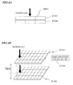
- FIG. 4A is a cross-sectional view illustrating the configuration of an image sensor which may be used in the first embodiment of the present disclosure.
- FIG. 4B is a perspective view illustrating the configuration of an image sensor which may be used in the first embodiment of the present disclosure.
- FIG. 5A is a cross-sectional view illustrating the configuration of another image sensor which may be used in the first embodiment of the present disclosure.
- FIG. 5B is a cross-sectional view illustrating the configuration of still another image sensor which may be used in the first embodiment of the present disclosure.
- FIG. 6 is a perspective view illustrating a polarization image sensor with color filters.
- FIG. 7 illustrates how the polarization image sensor operates with time.
- FIG. 8A shows a series of timings to control the rotation of a plane of polarization of the illuminating light and the rotation of a plane of polarization for image capturing temporally.
- FIG. 8B shows another series of timings to control the rotation of a plane of polarization of the illuminating light and the rotation of a plane of polarization for image capturing temporally.
- FIG. 9( a ) illustrates a situation where a plurality of pixels are included in a single groove
- FIG. 9( b ) illustrates a situation where a plurality of grooves are included in a single pixel.
- FIG. 10 Shows a function indicating the distribution of grooves in a single pixel.
- FIG. 11A Illustrates how intensity pattern images change as the polarization plane of a polarized light source rotates.
- FIG. 11B schematic representations illustrating how intensity pattern images change as the polarization plane of a polarized light source rotates.
- FIGS. 12( a ) and 12 ( b ) illustrate how incoming light that has come directly from over an object is incident on the object's surface and reflected once.
- FIG. 13 is a graph showing how the Fresnel reflectances of P- and S-wave energies change with the angle of incidence (that is represented as the abscissa).
- FIG. 14A is a graph showing how the intensity value of a pixel varies as the plane of polarization of polarized light is rotated.
- FIG. 14B is a photograph showing the surface shape of a sample that was used to get the data shown in the graph of FIG. 14A .
- FIG. 14C schematically illustrates the surface shape shown in FIG. 14B .
- FIG. 15( a ) shows the polarization directions of polarized light sources and FIG. 15( b ) shows how the light intensity varies according to the polarized light source.
- FIGS. 16( a ) and 16 ( b ) illustrate how the intensity of polarized reflected light varies due to interreflection.
- FIGS. 17( a ), 17 ( b ) and 17 ( c ) illustrate a groove on the object's surface as viewed from right over that surface.
- FIG. 18B illustrates a situation where reflected light is produced parallel and perpendicularly to the azimuth angle ⁇ of the groove in the state shown in FIG. 18A .
- FIG. 19 illustrates a situation where non-polarized light is incident on a groove and reflected light is produced parallel and perpendicularly to the azimuth angle ⁇ of the groove.
- FIG. 20 is a diagram illustrating a configuration for an image processing processor according to the first embodiment of the present disclosure.
- FIG. 21 shows how to make cosine function fitting based on samples of the polarized light intensities of four different kinds of polarized light sources.
- FIG. 22 shows how to make cosine function fitting based on samples of the polarized light intensities at four different kinds of polarized light observation angles.
- FIG. 23A shows the distributions of surface grooves' azimuth angles in a single pixel, which were obtained in an embodiment of the present disclosure.
- FIG. 23B shows the distributions of surface grooves' azimuth angles in a single pixel, which were obtained in an embodiment of the present disclosure.
- FIG. 24A illustrates, as an example, a stellar object with grooves.
- FIG. 24B schematically illustrates the object shown in FIG. 25A .
- FIG. 25 illustrates a configuration for an image processing processor as a second embodiment of the present disclosure.
- FIG. 26A illustrates a configuration according to a third embodiment of the present disclosure.
- FIG. 26B illustrates the appearance of the third embodiment of the present disclosure.
- the present inventors discovered via experiments that the polarization image sensor of prior art could not get accurate polarization information on a pixel-by-pixel basis. On top of that, a noticeable moiré pattern would be generated in the polarized image due to interference with the spatial frequency of the object and part of the color mosaic would turn into a polarization mosaic, thus debasing the quality of a full-color image reproduced, too.
- the present inventors perfected our invention in order to overcome such a problem and an object of the present invention is to provide, first and foremost, an image processing apparatus that can obtain polarization information on a pixel-by-pixel basis and that can get information about the object's surface micro-geometry within a single pixel based on that polarization information.
- An image processing apparatus includes a polarized light source which sequentially illuminates an object with three or more kinds of plane polarized light rays, of which the planes of polarization have mutually different angles, and a polarization image sensor which sequentially captures an image of the object that is being illuminated with each of the three or more kinds of plane polarized light rays. That is why information corresponding to an intensity maximizing angle image and a degree of intensity modulation image can be obtained simultaneously with a color image even without developing any special polarization image sensor. Consequently, the image processing apparatus of the present disclosure can estimate the distribution of the grooves' azimuth angles in a single pixel.
- an exemplary image processing apparatus includes a polarized light source 120 , a polarization image sensor 140 , a varying intensity processing section 160 , and a distribution estimating section 170 .
- the varying intensity processing section 160 and the distribution estimating section 170 are included in an image processing section 150 .
- the polarized light source 120 sequentially illuminates an object 100 with three or more kinds of plane polarized light rays, of which the planes of polarization have mutually different angles.
- On the surface of the object 100 of shooting according to the present disclosure there are multiple grooves 100 a . If the object 100 is the surface of an organism's organ, for example, very small grooves are observed on the surface of the object 100 .
- a plane polarized light ray is reflected by the groove 100 a on the surface of the object 100 and then incident on the polarization image sensor 140 .
- the polarization image sensor 140 shoots the object 100 sequentially.
- This polarization image sensor 140 obtains a plurality of polarization images by sequentially changing the direction of the polarized light transmission axis into three or more different ones at each pixel while the object 100 is being illuminated with each of those plane polarized light rays.
- to “sequentially change the direction of the polarized light transmission axis into three or more different ones at each pixel” means that the polarization direction of a light ray incident on each pixel changes into three or more different ones with time.
- every pixel may have the same polarized light transmission axis direction or pixels may have multiple different polarized light transmission axis directions.
- the point is that while the object 100 is being illuminated with a light ray that is polarized in a certain direction, the polarized light transmission axes of polarizers that are arranged in front of the respective pixels change into three or more different directions.
- FIG. 1B is a perspective view schematically showing the polarization directions of three kinds of plane polarized light rays, of which the planes of polarization have mutually different angles.
- the three polarization states 10 , 12 and 14 illustrated in FIG. 1B have planes of polarization that have mutually different angles.
- a double-headed arrow which indicates the vibration direction of the electric vector that defines the plane of polarization of a plane polarized light ray.
- the XYZ coordinates shown in FIG. 1B are of the right-handed system.
- the X- and Y-axes are defined in the plane of the image captured by the image sensor 140
- the direction of the Z-axis is defined to be the viewing direction (i.e., the optical axis direction).
- the plane of polarization of a plane polarized light ray is a plane that is parallel to the vibrating electric vector and that includes the optical axis. If this coordinate system is adopted, the electric vector vibration direction of the plane polarized light ray is parallel to the XY plane.
- the angle ( ⁇ I) of the plane of polarization is defined to be the angle formed by the polarization direction (i.e., the electric vector vibration direction) with respect to the positive X-axis direction.
- This angle ⁇ I will be described in detail later with reference to FIG. 3 .
- the polarized light source 120 sequentially illuminates the object 100 with three or more kinds of plane polarized light rays, of which the planes of polarization have mutually different angles. And while the object 100 is being illuminated with each of the three or more kinds of plane polarized light rays, the polarization image sensor 140 shoots the object 100 sequentially.
- the varying intensity processing section 160 obtains a relation between the angle of the plane of polarization and the intensity value of each pixel based on a pixel signal supplied from the polarization image sensor 140 , thereby generating an “intensity maximizing angle image” and a “degree of intensity modulation image”.
- the “intensity maximizing angle image” is an image that is defined by the angle of the plane of polarization that maximizes the intensity value with respect to each of the pixels that form the image captured.
- the intensity value of a pixel P (x, y) that is defined by a set of coordinates (x, y) becomes maximum when the object 100 is illuminated with a plane polarized light ray, of which the plane of polarization has an angle of 45 degrees
- an intensity maximizing angle of 45 degrees is set with respect to that pixel P (x, y).
- a single “intensity maximizing angle image” is formed by setting such an intensity maximizing angle value for each pixel.
- the “degree of intensity modulation image” is an image that is defined by the ratio of the amplitude of variation in the intensity value caused by the change of the plane of polarization to an average intensity value with respect to each pixel.
- a single “degree of intensity modulation image” is formed by setting such a degree of intensity modulation value for each pixel.
- an “image” refers herein to not only a light intensity image to be directly sensible to human eyes but also any arrangement of numerical values that are allocated to respective pixels. For example, if a single “intensity maximizing angle image” is displayed, the image can be displayed with lightness defined by the intensity maximizing angle value that has been set for each pixel of that intensity maximizing angle image.
- the intensity maximizing angle image represented in this manner does include a bright and dark pattern that is sensible to human eyes but that is different from an ordinary light intensity image representing the object's intensity.
- the data itself that represents any of various kinds of “images” will also be sometimes referred to herein as an “image” for the sake of simplicity.
- the distribution estimating section 170 shown in FIG. 1A estimates, based on the intensity maximizing angle image and the degree of intensity modulation image, the distribution in a single pixel of the azimuth angles of V-grooves 100 a on the object's ( 100 ) surface.
- the azimuth angle of a normal to a tilted surface in that V-groove 100 a is perpendicular to the direction in which the V-groove 100 a runs.
- the distribution estimating section 170 can estimate the distribution of azimuth angles of the V-grooves 100 a on a pixel-by-pixel basis. It will be described in detail later exactly on what principle the distribution estimating section 170 of the present disclosure estimates the distribution of azimuth angles of the V-grooves 100 a.
- FIG. 1C schematically illustrates an overall configuration for an image processing apparatus as a first embodiment of the present disclosure.
- This image processing apparatus includes an endoscope 101 and a controller 102 .
- the endoscope 101 includes a tip portion 113 with an image capturing sensor and an inserting portion 103 with a light guide 105 and a video signal line 111 .
- the inserting portion 103 of the endoscope 101 has a structure that is elongated horizontally and that can be bent flexibly. Even when bent, the light guide 106 can also propagate light.
- a flexible scope with a flexible inserting portion 103 such as the one of this embodiment and a rigid scope with an inflexible inserting portion.
- its inserting portion 103 has a structure for guiding returning light to an image sensor, which is located behind it, using a relay optical system, for example.
- the present disclosure is applicable to both a flexible scope and a rigid scope.
- the controller 102 includes a light source 104 , an image processing processor 3002 and a synchronizer 112 .
- the white non-polarized light that has been emitted from the light source 104 is guided through the light guide 105 to a plane of polarization control element 106 of the tip portion 113 .
- the plane of polarization control element 106 may be made up of a polarizer and a liquid crystal element and can transform the non-polarized light into plane polarized light with an arbitrary plane of polarization using a voltage.
- the plane of polarization control element 106 is a device that can rotate the plane of polarization using a liquid crystal material. Its exemplary configurations are already disclosed in Japanese Laid-Open Patent Publication No. 11-313242, United States Laid-Open Patent Publication No. 2009/0079982, and Nicolas Lefaudeux, et al., “Compact and Robust Linear Stokes Polarization Camera”, Proc. SPIE, Vol. 6972, 69720B, Polarization: Measurement, Analysis, and Remote Sensing VIII (2008) and so on.
- the plane of polarization control element 106 may be implemented as a voltage application type liquid crystal device that includes a ferroelectric liquid crystal material, a polarization film and a quarter-wave plate in combination. The plane of polarization control element 106 transforms the non-polarized light that has been produced by the light source 104 and then transmitted through the light guide 105 into plane polarized light that has a plane of polarization at an arbitrary angle.
- the synchronizer 112 gives the plane of polarization control element 106 an instruction to rotate the plane of polarization, thereby getting the plane of polarization of the illumination rotated. And that polarized illumination is cast toward the object through an illuminating lens 107 . At the same time, the synchronizer 112 sends a shooting start signal to an image sensor 3001 , thereby getting video. The synchronizer 112 performs this series of processing steps a number of times.
- the light returning from the object is transmitted through a shooting lens 109 and then produces an image on the image sensor 3001 , the configuration and operation of which will be described later.
- the video signal representing the image captured is output from the image sensor 3001 and transmitted through the video signal line 111 to reach the image processor 3002 .
- the polarized light source 120 shown in FIG. 1A is realized by the light source 104 , the light guide 105 , the plane of polarization control element 106 and the illuminating lens 107 .
- the polarization image sensor 140 shown in FIG. 1A is realized by the shooting lens 109 and the image sensor 3001 .
- the varying intensity processing section 160 and the distribution estimating section 170 shown in FIG. 1A are realized by the image processor 3002 .
- First, second, third and fourth images are captured in respective states 203 , 204 , 205 and 206 in which the plane of polarization has an angle of 0, 45, 90 and 135 degrees, respectively. These angles do not always have to be increased on a 45 degree basis. But the angle of increment may also be any other value obtained by dividing 180 degrees by an integer of three or more. If the image sensor has high sensitivity or if the illumination has high illuminance, then the exposure time can be shortened. As a result, the angle of rotation can be set more finely.
- the time it takes to rotate the plane of polarization may be as long as approximately 20 ms when the operating speed is low but may also be as short as 40 to 100 ⁇ sec when the operating speed is high. If a high-response-speed liquid crystal material is used and if the sensitivity of the image sensor is increased to a level that is high enough to get an image captured in such a short time, performance that is high enough to shoot a moving picture can be maintained even when the plane of polarization is rotated to those four directions one after another during shooting.
- the optical axis of the illuminating lens 107 is substantially aligned with that of the shooting lens 109 . This arrangement is adopted in order to avoid casting shadows on the object as perfectly as possible when the object is monitored with an endoscope.
- the object when an endoscope is used normally, the object should be irradiated with non-polarized light in many cases.
- a non-polarized average light intensity image can be generated.
- the present inventors discovered via experiments that when the images represented by multiple polarized light rays, of which the planes of polarization were defined by angles ⁇ I at regular intervals and which had been radiated toward, and had returned from, the object, were added together, the effect of polarization was canceled and the effect eventually achieved was the same as the one achieved by using a non-polarized light source.
- FIG. 3 shows how the plane of polarization of polarized light source has its angle ⁇ I defined.
- an X-Y coordinate system is defined with respect to the object.
- the angle ⁇ I of the plane of polarization is defined to be positive in the positive Y-axis direction with the negative X-axis direction set to be 0 degrees. If the angle ⁇ I is saved for reflected light, then the respective planes of polarization of the reflected light and the incident light will have the same angle. And if the angle ⁇ I of the plane of polarization is going to be increased or decreased, the same polarization state will recur over and over again in a period of 180 degrees.
- a function that uses the angle ⁇ I of the plane of polarization as a variable is a periodic function that has a period of 180 degrees.
- the angle ⁇ I of the plane of polarization of polarized light source will be sometimes referred to herein as an “incident plane of polarization angle”.
- FIGS. 4A and 4B are respectively a cross-sectional view and a perspective view illustrating the configuration of a main portion of the polarization image sensor 3001 .
- This polarization image sensor 3001 includes a plane of polarization changer 3101 which is located closer to the light source and an intensity image sensor 3102 which receives the light that has been transmitted through the plane of polarization changer 3101 .
- the intensity image sensor 3102 is an image sensor (such as a CCD or MOS sensor) which obtains intensity information by capturing an image.
- one pixel of the intensity image sensor 3102 corresponds to one pixel of the plane of polarization changer 3101 unlike the known pattern polarizer mosaic polarization image sensor.
- the plane of polarization changer 3101 includes a liquid crystal layer and two electrodes that sandwich the liquid crystal layer between them, and can control the optical property of the liquid crystal layer upon the application of a voltage to the electrodes.
- each pixel may be set to transmit plane polarized light, which is polarized in an arbitrary direction, independently of the other pixels.
- the plane of polarization changer 3101 of this embodiment operates so that every pixel has a polarized light transmission plane in the same direction.
- the plane of polarization changer 3101 can work so as to sequentially change the polarization directions of light rays to be incident on respective pixels of the intensity image sensor.
- the resolution of the polarization image can maintain the resolution of the intensity image sensor 3102 .
- the plane of polarization changer 3101 can quickly change the polarized light transmission directions into any of the four directions (such as the ones defined by 0, 45, 90 and 135 degrees) with time.
- the polarization image sensor 3001 of this embodiment can obtain the degree of polarization and the angle of polarization on a pixel-by-pixel basis.
- the distance Dps between the plane of polarization changer 3101 and the intensity image sensor 3102 is substantially equal to zero. That is why if the polarized light transmission axis of the polarizer that is located right in front of each pixel has changed into three or more directions, no pixel positions shift between the polarizer and the image sensor and good polarization information can be obtained. As a result, a fine super-resolution function can be used effectively within a single pixel.
- FIGS. 5A and 5B illustrate other configurations for the polarization image sensor 3001 .
- a color image and a polarization image can be captured at the same time on a pixel-by-pixel basis.
- incoming light passes through color filters 3201 first and the plane of polarization changer 3101 next, and then reaches the intensity image sensor 3102 .
- FIG. 5B incoming light passes through the plane of polarization changer 3101 first and the color filters 3201 next, and then reaches the intensity image sensor 3102 .
- FIG. 6 is a perspective view illustrating the configuration shown in FIG. 5A in further detail.
- the distance Dcp between the color filters 3201 and the plane of polarization changer 3101 and the distance Dcs between the plane of polarization changer 3101 and the intensity image sensor 3102 are both substantially equal to zero.
- FIGS. 7 and 8A illustrate how this polarization image sensor operates.
- FIG. 7 shows that polarized light intensities about four directions with mutually different ⁇ can be obtained for each pixel of the image sensor.
- the polarization state of that light changes from the state 3301 into the states 3302 , 3303 and 3304 . That is to say, at the corresponding pixel of the plane of polarization changer 3101 , the plane of the transmitted polarized light rotates to have four different direction ⁇ of 0, 45, 90 and 135 degrees.
- the polarized light intensities in the respective directions are observed temporally sequentially.
- polarized light intensities are separately observed in four directions.
- the pixels 3305 and 3306 may have two independent sets of observation angles, the plane of the transmitted polarized light is supposed in this example to rotate in the same phase at every pixel.
- FIG. 8A shows the timings when the synchronizer 112 shown in FIG. 1C makes the polarization image sensor operate temporally synchronously with the illuminating light, of which the plane of polarization is rotated by the plane of polarization control element 106 .
- the abscissa indicates the passage of time.
- images are captured with the plane of polarization of the polarization image sensor 3001 rotated at high speeds to define the angles ⁇ of 0, 45, 90 and 135 degrees in this order.
- the polarization images do not have to be captured following the pattern shown in FIG. 8A .
- the timings to capture polarization images may also be controlled so that the plane of polarization of the illumination is rotated to every angle ⁇ I with respect to single ⁇ as in the example illustrated in FIG. 8B .
- the control operation may also be carried out using a different timing chart in which these two patterns are combined together.
- the variation in polarized light intensity as ⁇ changes into four different values through the rotation is also subjected to fitting processing using a trigonometric function as in the variation in light intensity that has been described for the first embodiment. That processing will be described in detail later.
- Portions (a) and (b) of FIG. 9 are top views respectively illustrating a relatively large groove on the object and a plurality of grooves that are smaller than a single pixel.
- the single groove 3301 is larger than the single pixel 3302 .
- FIG. 10 illustrates the distribution of grooves in a single pixel.
- the direction of each of those grooves is supposed to be defined by the angle ⁇ that indicates the direction that intersects with the principal axis of the groove at right angles.
- a distribution function D( ⁇ ) represented by polar coordinates, of which the radial length is defined by the histogram frequency in the ⁇ direction. That is to say, as the function of the angle ⁇ indicated by the arrow 3502 shown in FIG. 10 , the distance from the origin to the tip 3503 of the arrow 3502 is represented by D( ⁇ ).
- the grooves 3301 included in a single pixel have random directions.
- the eight grooves 3301 a , 3301 b , . . . and 3301 h shown around the distribution function D( ⁇ ) schematically illustrate grooves, of which the angle ⁇ are 0, 45, . . . and 325 degrees, respectively.
- D( ⁇ ) means estimating the distribution in a single pixel of the azimuth angles of grooves on the surface of an object.
- the fundamental period is 180 degrees, and therefore, the groove directions that can be estimated also have a period ⁇ .
- This distribution function can be subjected to a Fourier series expansion with respect to ⁇ in the following manner:
- the object is not the mucosa of an organism's organ but an object made of a general material such as plastic or wood as an example.
- This example is taken because light is basically specular-reflected from the surface of the mucosa and because specular reflection from the surface of a dielectric material can be regarded as the same physical phenomenon irrespective of the material of the object.
- FIGS. 11A and 11B illustrate polarized images of a ceramic cup with a smooth surface and a wood plate with microfacet that were captured as objects by the present inventors.
- the two images on the left-hand side of FIG. 11A are light intensity images that are obtained when the object is illuminated with polarized light with an incident plane of polarization angle ⁇ I of 0 degrees.
- the two images on the right-hand-side of FIG. 11A are light intensity images that are obtained when the object is illuminated with polarized light with an incident plane of polarization angle ⁇ I of 90 degrees.
- the four images shown in FIG. 11B are schematic representations of the four images shown in FIG. 11A .
- the polarization plane of the polarized light was changed, no significant variation was observed in the intensity pattern of the ceramic cup with the smooth surface.
- the wood plate with a lot of micro-geometry on the other hand, it turned out that when the angle ⁇ I of the polarization plane of the polarized light was changed, a significant variation occurred in the light intensity image observed as can be seen easily from the images shown at the bottom of FIGS. 11A and 11B .
- Such a difference can be explained as follows.
- FIG. 12 illustrates how polarized light is incident on the surface 801 at an angle of incidence that is close to zero degrees and how the specular reflected light is observed with a camera.
- the respective angles defined by the polarization planes of the incident polarized light are different from each other by 90 degrees between portions (a) and (b) of FIG. 12 .
- the intensity (i.e., the energy) of the reflected light is almost the same as that of the incident light for the following reasons:
- FIG. 13 is a graph showing the dependence of the specular reflectance according to the Fresnel theory on the angle of incidence.
- the abscissa represents the angle of incidence and the ordinate represents the Fresnel reflectance.
- These dependence curves are drawn on the supposition that the refractive index NN is 1.8.
- both P and S waves have substantially the same reflectance in this range 901 .
- the polarized light is incident substantially perpendicularly onto the surface, then it makes almost no difference for the surface and the light is reflected in the same behavior, no matter whether the polarized light is actually a P-wave or an S-wave. This fact is satisfied extensively by any natural object with a refractive index n of 1.4 to 2.0.
- FIG. 14A is a graph showing how the intensity value of the same pixel varied in a situation where a light intensity image was shot with the plane of polarization of the polarized light, impinging on the surface of a wood plate, changed.
- FIG. 14B is a light intensity image of that wood plate as the object of shooting (i.e., a light intensity image under non-polarized light).
- FIG. 14C schematically illustrates the surface micro-geometry of the wood plate shown in FIG. 14B .
- FIG. 15 shows the behavior of the intensities Y of a particular pixel of a light intensity image that were obtained when the plane of polarization of the polarized light had angles ⁇ I of 0, 45, 90 and 135 degrees, respectively.
- the intensity Y varied periodically according to the angle ⁇ I of the plane of polarization of each polarized light.
- the surface of the wood plate is not smooth but has a lot of grooves, where the incident light produces interreflection. Consequently, the intensity Y would vary according to the angle ⁇ I of polarization of the light. The reason will be described in detail below.
- FIG. 16 illustrates how a groove 1201 that has been formed on a surface produces interreflection twice on its slopes. That kind of interreflection would be produced on an uneven surface of various natural objects including cloth, wood, human skin and leather.
- the properties of reflections are important the first and second times around, but the interreflection is almost negligible for the third time and on, because the intensity is small.
- the interreflection occurs twice will be described.
- the properties of reflection are roughly classified into specular reflection and diffuse reflection, there should arise one of the following four situations:
- situation 4 in which specular reflection is produced both of the first and second times around, may be regarded as the dominant phenomenon. If the tilted surface in the groove is not quite smooth and if the illumination is not quite parallel light, even specular reflected light is not ideal one. That is why the present inventors confirmed via experiments that even if the specular reflection condition was not satisfied completely, these two reflections could be observed, and the image could be captured, relatively easily and the polarization property was caused by the specular reflection.
- portions (a) and (b) of FIG. 16 look at portions (a) and (b) of FIG. 16 , in which illustrated is a portion of a groove 1201 on the surface of an object.
- the groove 1201 runs in one direction, which will be referred to herein as the “principal axis direction”.
- the groove 1201 does not have to run linearly but may be a curved one, too. Even in such a curved groove, its portion can also be approximated to be a linear groove that runs in the principal axis direction.
- a cross section of the groove 1201 on the object's surface can be approximated to be a V-shape. That is why a groove on the surface of an organism's organ can be called a “V-groove”.
- a cross section of such a V-groove does not have to have an exactly V-shape but may have a curved portion, too.
- the following description is applicable.
- polarized light incident perpendicularly to the principal axis direction 1202 of the groove is a P-wave.
- the reflectance of a P-wave becomes much lower than that of an S-wave in the range 902 of that angle of incidence as can be seen from the graph showing the Fresnel reflectance.
- the reflectance of the P-wave further decreases as the P-wave goes through reflection first and second times around.
- the surface groove is supposed to be as such, the variation in the intensity of the reflected light that was caused by rotating the plane of polarization of the incident light in an experiment can be accounted for.
- the present inventors discovered that the function representing the variation in intensity Y that was caused by getting the polarized light reflected twice from the groove changed in substantially the same way as in a situation where non-polarized light was incident there. Hereinafter, this respect will be described.
- FIG. 17( a ) illustrates a groove on the object's surface as viewed from right over that surface, which corresponds to looking down on FIG. 16 from right over the paper.
- FIG. 17( a ) shown are X and Y coordinates on a plane that is parallel to the image capturing plane.
- the angle ⁇ formed between the direction that intersects at right angles with the principal axis direction 1202 of the groove 1201 and the positive X-axis direction.
- FIG. 17( b ) shows the angle ⁇ I of the plane of polarization of the polarized light that has been incident on the object.
- FIG. 17( c ) illustrates, in combination, what is illustrated in FIGS. 17( a ) and 17 ( b ) in the same drawing.
- the direction of the groove will be specified herein by the angle ⁇ , which is different from the azimuth angle of the groove's principal axis by 90 degrees.
- the direction of the groove is specified by the angle ⁇ .
- the incident light is reflected twice in the groove as shown in FIG. 16 .
- the intensity of plane polarized light, of which the plane of polarization has a certain angle ⁇ is measured.
- FIG. 18B shows the angle ⁇ of the plane polarized light, of which the intensity is measured.
- the intensity at the angle ⁇ is represented by I ( ⁇ , ⁇ )
- Equation (4) this polarized light intensity I ( ⁇ , ⁇ ) can be represented by the following Equation (4):
- I ⁇ ( ⁇ , ⁇ ) ( A + B ) 4 + ( A - B ) 4 ⁇ cos ⁇ ⁇ 2 ⁇ ⁇ + [ ( A + B ) 8 + ( A - B ) 4 ⁇ cos ⁇ ⁇ 2 ⁇ ⁇ + ( A + B ) 8 ⁇ cos ⁇ ⁇ 4 ⁇ ⁇ ] ⁇ cos ⁇ ⁇ 2 ⁇ ⁇ + [ ( A - B ) 4 ⁇ sin ⁇ ⁇ 2 ⁇ ⁇ + ( A + B ) 8 ⁇ sin ⁇ ⁇ 4 ⁇ ] ⁇ sin ⁇ ⁇ 2 ⁇ ⁇ ( 4 )
- the polarized light intensity I ( ⁇ , ⁇ ) varies in the period ⁇ with respect to ⁇ .
- the incident plane of polarization angle is the general value ⁇ I instead of 0 degrees.
- the polarized light intensity in a situation where the incident plane of polarization angle is ⁇ I and the viewing angle is ⁇ is given by the following Equation (5):
- the light intensity PY ( ⁇ I, ⁇ ) to be measured in a situation where polarized light with an incident plane of polarization angle ⁇ I is incident on a groove that is specified by an angle ⁇ and then reflected twice can be represented as a periodic function of 180 degrees with respect to ⁇ I as in the following Equation (6):
- the amplitude of variation considering that the cosine function term varies within the range of +1 through ⁇ , the degree of modulation of the intensity variation can be considered. And that ratio will be referred to herein as a “degree of light intensity modulation YD”, which can be calculated by the following Equation (7):
- the intensity maximizing angle YPH and the degree of intensity modulation YD are given on a pixel-by-pixel basis. That is why an image, in which the intensity maximizing angle YPH is set for each of the constituent pixels thereof, will be referred to herein as an “intensity maximizing angle image YPH”. Likewise, an image, in which the degree of intensity modulation YD is set for each of the constituent pixels thereof, will be referred to herein as a “degree of intensity modulation image YD”.
- the intensity maximizing angle YPH and the degree of intensity modulation YD are quantities corresponding to a polarized light principal axis angle and a degree of polarization, respectively, in normal polarized light measuring.
- their quantitative relation has not been defined clearly yet.
- polarization state twice-reflected light will have in a situation where non-polarized light has been incident on a groove.
- FIG. 19 illustrates a situation where non-polarized light 1501 has been incident on a groove. If the non-polarized light 1501 has been incident on a groove that has an angle ⁇ , then its energy would be equally distributed to the principal axis direction of the groove and the direction that intersects with the former direction at right angles. That is why energies multiplied by their energy reflectances A and B would be emitted in that groove's principal axis direction and the direction that intersects with the principal axis direction at right angles, respectively.
- the polarized light intensity will have its maximum value (at the reflectance B) in the groove's principal axis direction and have its minimum value (at the reflectance A) in that direction that intersects with the principal axis direction at right angles as already described with reference to FIG. 16 .
- the degree of polarization DOP is calculated by the following Equation (8):
- the intensity maximizing angle YPH which is the phase angle of the light intensity variation in a situation where the angle ⁇ I of the plane of polarization of polarized light has been rotated, agrees with the polarized light principal axis when non-polarized light is radiated.
- the degree of intensity modulation YD which is the amplitude of the light intensity variation in a situation where the angle ⁇ I of the plane of polarization of polarized light has been rotated, agrees with the degree of polarization DOP when non-polarized light is radiated. Consequently, the Fresnel reflection theory and the surface normal discussion on the supposition that non-polarized light is radiated can be used to analyze a variation in polarized light intensity according to the present disclosure.
- the image processing processor 3002 of this embodiment gets the intensity maximizing angle image YPH and the degree of intensity modulation image YD as described above, thereby obtaining information about the object's surface micro-geometry.
- Equation (5) The polarized light intensity in a particular direction ⁇ in a situation where polarized light ⁇ I has been incident on one groove, of which the direction is defined by an angle ⁇ , is given by the following Equation (5).
- Equation (1) To calculate the intensity observed from a set of grooves with the distribution represented by Equation (1), double integration is performed in the grooves' direction and in the observation direction:
- Equation (9) If integration is performed by substituting Equations (1) and (5) into Equation (9), then not only every odd number of times frequency term but also 4 ⁇ or more even number of times frequency term of the Fourier series will disappear. As a result, the result of the double integration represented by Equation (9) becomes as follows:
- P_P ⁇ ( ⁇ I , ⁇ ) ⁇ ⁇ ⁇ ⁇ a 0 ⁇ A + B 4 + a 2 ⁇ ⁇ ⁇ ( A - B ) 8 ⁇ cos ⁇ ⁇ 2 ⁇ ⁇ I + b 2 ⁇ ⁇ ⁇ ( A - B ) 8 ⁇ sin ⁇ ⁇ 2 ⁇ ⁇ I + ⁇ [ a 0 ⁇ ⁇ ⁇ ( A + B ) 8 + a 2 ⁇ ⁇ ⁇ ( A - B ) 8 ⁇ cos ⁇ ⁇ 2 ⁇ ⁇ I + b 2 ⁇ ⁇ ⁇ ( A - B ) 8 ⁇ sin ⁇ ⁇ 2 ⁇ ⁇ I + a 4 ⁇ ⁇ ⁇ ( A + B ) 16 ⁇ cos ⁇ ⁇ 4 ⁇ ⁇ I + b 4 ⁇ ⁇ ⁇ ( A + B ) 16 ⁇ sin ⁇ ⁇ 4 ⁇ ] ⁇ cos ⁇ ⁇ 2 ⁇
- the distribution of the grooves' azimuth angles within a single pixel can be estimated. More specifically, by observing the intensity variation and polarized light intensity variation in a situation where plane polarized light is incident with the angle ⁇ I changed, the distribution function of the grooves within a single pixel can be estimated as the coefficients a 0 , a 2 , b 2 , a 4 and b 4 of the Fourier series expansion. If only the intensity variation is observed, a 0 , a 2 and b 2 can be estimated.
- the coefficients a 4 and b 4 can also be estimated. However, no more coefficients can be estimated. Consequently, the distribution of the azimuth angles of the grooves can be estimated symmetrically with respect to a half period ⁇ .
- FIG. 20 is a block diagram illustrating an exemplary configuration for the image processing processor 3002 .
- the reflectance setting section 3609 sets in advance the numerical values of A and B representing the energy reflectances in the groove principal axis direction, which depends on the object's material property such as the refractive index, and in the direction that intersects with the former direction at right angles.
- These numerical A and B values are what has already been described with reference to FIG. 13 .
- a and B may be set to be 0.05 and 0.2, respectively, according to the Fresnel theory.
- the group 3601 of polarized light intensity images is input to the varying intensity processing section 1602 , which obtains a non-polarized light average light intensity image 1612 , an intensity maximizing angle image 1603 and a degree of intensity modulation image 1605 by making the calculations to be described below.
- FIG. 21 shows the cosine function of this intensity variation and indicates the meanings of the amplitude AI, the phase ⁇ o and the average Y ⁇ I — ave described above.
- the four sample points are plotted right on that cosine function for the sake of simplicity.
- the intensity Y ⁇ I — ave of the original image under non-polarized light is calculated by the following Equation (15).
- the right side of this Equation (15) means adding together, and calculating the average of, four light intensity images that have been obtained from an object that is illuminated with polarized light at angles ⁇ I of 0, 45, 90 and 135 degrees, respectively.
- the intensity Y ⁇ I — ave approximately reproduces a light intensity image under non-polarized light and can be used as a normally observed image for an endoscope. That is why the intensity Y ⁇ I — ave can be referred to herein as a “non-polarized light average light intensity image”.
- the optimum fitting process is begun by carrying out sampling in the four directions that are defined by 0, 45, 90 and 135 degrees, respectively. Since the cosine function is determined by the three kinds of information that are amplitude, phase and average, the number of samples for use to determine the cosine function does not have to be four but may actually be any other number as long as the number is at least three. Nevertheless, if samples are taken at a regular interval of 45 degrees in this manner, the optimum fitting can be simplified.
- Normal optimum fitting to a cosine function can be carried out on three or more samples and its method is disclosed in Japanese Patent Publication No. 4235252, for example.
- the intensity maximizing angle image 1603 and the degree of intensity modulation image 1605 can be obtained.
- the intensity maximizing angle image 1603 and the degree of intensity modulation image 1605 are identified by the reference signs YPH and YD, respectively.
- the intensity maximizing angle image YPH and the degree of intensity modulation image YD are passed to a second-order coefficient estimating section 3603 .
- the varying intensity processing section 1602 deals with an intensity variation involved with a variation in the plane of polarization angle ⁇ I of the illumination irrespective of observation of polarized light.
- the second order coefficient estimating section 3603 calculates a Fourier expansion coefficient by Equation (9) using the intensity maximizing angle image 1603 and the degree of intensity modulation image 1605 that have been obtained by processing the intensity variation.
- the second order coefficient estimating section 3603 calculates the average intensity 1612 in the same way as in Equation (15). That is to say, by using only a polarized light source as the illumination and by adding together, and calculating the average of, the light intensity images that have been captured with the plane of polarization rotated, a light intensity image under a non-polarized light source can be reproduced approximately. Thus, there is no need to switch the illuminating light between a normal observation mode and a polarized light observation mode, thus enabling the image processing processor to perform both of these functions. And these functions can be performed no matter whether the image is a monochrome one or a colored one. Consequently, a color light intensity image can be obtained under a normal non-polarized white light source. Furthermore, based on this average intensity 1612 , i.e., Y ⁇ I — ave , the expansion coefficient a 0 can be obtained by the following Equation (26):
- a 2 and b 2 can be calculated by
- This function includes three kinds of information about amplitude, phase and average.
- FIG. 22 shows the cosine function of this intensity variation and indicates the meanings of the amplitude, phase and average described above.
- the four sample points are plotted right on that cosine function for the sake of simplicity. Since the specific procedure of estimating these values by making fitting to a cosine function using four angular samples that are plotted at regular intervals is the same as in making fitting for the intensity variation, description thereof will be omitted herein.
- the average intensity Y ⁇ — ave is calculated by the following Equation (29).
- This average of the sum corresponds to a light intensity image obtained by calculating the average of the polarized light images under a polarized light source with an angle ⁇ I. This image will be referred to herein as an average intensity image 3610 .
- the polarized light maximizing angle image PPH is generated by regarding the ⁇ 0 value that maximizes Equation (12) as the polarized light maximizing angle image PPH as it is.
- the degree of polarization image (DP) 3606 is generated by Equation (8) using the maximum and minimum values of Equation (12).
- the average intensity image Y ⁇ — ave 3610 , the polarization maximizing angle image PPH 3604 , and the degree of polarization image DP 3606 are all determined on the basis of the angle of the polarized light source ⁇ I. That is why in the example shown in FIG. 20 , each of these images consists of four pictures that are associated with the respective angles of the light source.
- the fourth order estimating section 3607 estimates the expansion coefficients a 4 and b 4 based on these images.
- the angle of the polarization maximizing angle image PPH is supposed to be ⁇ .
- the DP image has the original DP value as it is. In that case, the following relations are satisfied:
- ⁇ and ⁇ can be calculated by the following Equation (31) using the Y ⁇ —ave , ⁇ and DP values.
- [ ⁇ ⁇ ] 16 A + B ⁇ [ ⁇ ⁇ - ( ( A + B ) 8 ⁇ a 0 + a 2 ⁇ ( A - B ) 8 ⁇ cos ⁇ ⁇ 2 ⁇ ⁇ I + b 2 ⁇ ( A - B ) 8 ⁇ sin ⁇ ⁇ 2 ⁇ ⁇ I ) ⁇ ⁇ - ( - a 2 ⁇ ( A - B ) 8 ⁇ sin ⁇ ⁇ 2 ⁇ ⁇ I + b 2 ⁇ ( A - B ) 8 ⁇ cos ⁇ ⁇ 2 ⁇ ⁇ I ] ( 32 )
- Equation (33) the equation to be solved to obtain the expansion coefficients a 4 and b 4 becomes simultaneous equations with excessive constraints, and therefore, can be solved using a pseudo-inverse matrix.
- ⁇ I0 , ⁇ I1 , ⁇ I2 and ⁇ I3 mean 0, 45, 90 and 135 degrees, respectively.
- FIGS. 23A and 23B show the results of experiments in which the distribution of the azimuth angles of normals within a single pixel was actually obtained using the Fourier expansion coefficients that had been obtained as described above.
- the object was supposed to be a single pixel that was present inside the grooves A through H of the object shown in FIGS. 24A and 24B and rendering was carried out with the expansion coefficients substituted into Equation (1).
- FIG. 24 shows that object, which is a plastic plate through which eight grooves A through I were cut and which was painted.
- object which is a plastic plate through which eight grooves A through I were cut and which was painted.
- FIG. 24A is a photograph showing a light intensity image that was obtained by shooting the real object
- FIG. 248 is a schematic representation thereof. Two adjacent grooves within this plane had an azimuth angle interval of 22.5 degrees.
- Table 1 shows the expansion coefficients that were obtained at respective groove positions.
- the principal axes of the distributions of the grooves A through H rotate gradually. Even though there should be no direct correlation between the principal axis of the distribution of a groove within a single pixel and the direction of a macroscopic groove, the principal axis of the distribution of normals still turned out to be present on the slope direction of the groove.
- this technique is also applicable as an aid for making a diagnosis based on an endoscope image by using the expansion coefficients obtained in this embodiment as a feature quantity for classifying and recognizing the pattern of the objects' surfaces based on the statistical quantities of the grooves.
- FIG. 25 illustrates a second embodiment of the present disclosure and shows a portion of the image processing processor 3002 shown in FIG. 1C .
- the incoming light can be separated into light scattered from the surface of an organ and light scattered from a depth of a tissue.
- the polarized light processing section 3602 shown in FIG. 20 is replaced with a polarized light processing section 3901 shown in FIG. 25 , which is a difference from the configuration of the first embodiment.
- polarization endoscopes are designed mainly for the purpose of obtaining a high contrast image by separating the light scattered from the surface of an organ from the light scattered from a depth of a tissue.
- a P wave is used as a polarized light source and an S wave is used to observe an image. That is to say, polarized light that is polarized in a predetermined direction needs to be used and another polarized light, of which the polarization direction is perpendicular to the former direction, needs to be observed.
- the image processing apparatus of this embodiment includes a light source that rotates the plane of polarization and a polarization image sensor, and therefore, can carry out easily both the normal color shooting and the polarization image capturing.
- the four polarized light intensities at each pixel can be regarded as the four sample points indicated by the open circles in FIG. 22 . And those four polarized light intensities are fit to a cosine function.
- Ymax and Ymin shown in FIG. 22 are determined.
- the surface scattered light Is and the internally scattered light Id can be separated from each other without adding any special mechanism to the apparatus of the first embodiment.
- the intensities described above may be processed as respective color components. In that case, a normal non-polarized color image is obtained by Equation (29) and a color image in the same wavelength range, of which the components have been separated using polarized light, is obtained by Equation (34).
- the polarized light source angle ⁇ I can be freely changed from 0 degrees into any other value. That is why it can be calculated what result will be obtained when observation is carried out by using the direction that is perpendicular to that polarization direction as the polarized light transmission axis at an arbitrary polarized light source angle ⁇ I.
- intensity variations in a situation where the polarization observation angle ⁇ is fixed at 0 degrees and where the polarized light source angle ⁇ I is changed from 0 degrees into 45, 90 and 135 degrees may be used.
- the image processing apparatus of this embodiment is applicable to not only an endoscope but also a camera with illumination for medical purposes (which may be used in a dermatologist's or a dentist's), a fingerprint scanner, an optical surface analyzer and other devices.
- FIG. 26A illustrates an exemplary configuration according to this embodiment.
- the image processing apparatus of this embodiment uses a device 400 instead of the endoscope 101 shown in FIG. 1C .
- the device 400 includes a ring light 4001 , a ring plane of polarization control element 4002 , a shooting lens 4003 and an image sensor 4004 .
- FIG. 26B illustrates a general appearance of the device shown in FIG. 26A .
- the ring plane of polarization control element 4002 is arranged on the ring light 4001 .
- a non-polarized light ray is input through a light guide such as an optical filter to the ring light 4001 and the plane of polarization control element 4002 and has its plane of polarization rotated in the order of 0, 45, 90 and 135 degrees as shown in FIG. 2 .
- the ring light 4001 may also be a self-emitting light source such as an LED without using such a light guide that propagates the light emitted from a light source.
- the ring light may also be replaced with a strobe light.
- the ring light is used, even an object that would be hard to observe with only one light can also have its surface micro-geometry and grooves estimated with high precision.
- this device can be used effectively as a device for scanning the surface of a product for any scratches or checking its micro-geometry, a fingerprint scanner, or a skin unevenness checker for a dermatologist.
- the image processing processor of the first embodiment can be used.
- the plane polarized light as the light source is supposed to be rotated on a 45-degree-a-time basis.
- the angle of rotation does not have to be the same, but may be changed, each time.
- the angular interval does not have to be 45 degrees, either.
- at least three samples are needed. That is to say, as for plane polarized light as a light source, its angle of rotation should be changed into three or more different values. For example, if three sample angles are used, the three angles of 0, 60 and 120 degrees may be selected, for example.
- the present disclosure is broadly applicable to the field of image processing that needs observing, checking, or recognizing the object's surface micro-geometry using a medical endoscope camera, a medical camera for dermatologists, dentists, internists or surgeons, an industrial endoscope camera, a fingerprint scanner, or an optical surface analyzer.
Landscapes
- Health & Medical Sciences (AREA)
- Life Sciences & Earth Sciences (AREA)
- Surgery (AREA)
- Engineering & Computer Science (AREA)
- Physics & Mathematics (AREA)
- Optics & Photonics (AREA)
- Medical Informatics (AREA)
- Veterinary Medicine (AREA)
- Biophysics (AREA)
- Pathology (AREA)
- Radiology & Medical Imaging (AREA)
- Nuclear Medicine, Radiotherapy & Molecular Imaging (AREA)
- Biomedical Technology (AREA)
- Heart & Thoracic Surgery (AREA)
- Public Health (AREA)
- Molecular Biology (AREA)
- Animal Behavior & Ethology (AREA)
- General Health & Medical Sciences (AREA)
- Signal Processing (AREA)
- General Physics & Mathematics (AREA)
- Multimedia (AREA)
- Computer Vision & Pattern Recognition (AREA)
- Theoretical Computer Science (AREA)
- Endoscopes (AREA)
- Blocking Light For Cameras (AREA)
- Stroboscope Apparatuses (AREA)
- Image Processing (AREA)
- Studio Devices (AREA)
- Exposure Control For Cameras (AREA)
- Investigating Materials By The Use Of Optical Means Adapted For Particular Applications (AREA)
- Investigating Or Analysing Materials By Optical Means (AREA)
Abstract
Description
where a0, a1, b1, a2, b2 and so on are coefficients. To determine the distribution function D(ψ) these coefficients may be used.
-
- 1) diffuse reflection the 1st time around and specular reflection the 2nd time around;
- 2) diffuse reflection both of the 1st and 2nd times around;
- 3) specular reflection the 1st time around and diffuse reflection the 2nd time around; and
- 4) specular reflection both of the 1st and 2nd times around.
I(ψ,φ)=A cos2 ψ cos2(ψ−φ)+B sin2 ψ sin2(ψ−φ) (3)
As can be seen from this Equation (4), the polarized light intensity I (ψ, φ) varies in the period π with respect to φ.
If calculation is made with Equations (5) and (1) substituted into this Equation (11), then
where P_Y is the intensity variation portion represented by Equation (10) and α and β are supposed to be as follows:
Y(ψI)=Y ψI
The phase ψo of the cosine function that minimizes this square error can be calculated by the following Equation (17):
Based on this equation, the solutions can be given by the following Equations (18) and (19):
A mathematical function such as an inverse trigonometric function generally imposes the following constraint:
0≦a cos(x)≦π (20)
YPH=ψ 0max (22)
Y max =Y ψI
Y min =Y ψI
Only these expansion coefficients can be obtained by observing the intensity variation. To obtain a4 and b4, on the other hand, polarized light needs to be observed.
Y(φ)=Y φ
| TABLE 1 | |||||
| Pixel position | Coefficient | Coefficient | Coefficient | Coefficient | Coefficient |
| (groove) | a0 | a2 | a4 | b2 | b4 |
| A | 69.708975 | 27.466445 | 2.558916 | −1.503381 | 2.267980 |
| B | 69.708975 | 17.949969 | 13.525970 | −2.808555 | 2.072687 |
| C | 71.330113 | −0.297917 | 14.392751 | 1.252213 | 5.048574 |
| D | 66.466697 | −14.457502 | 17.691217 | 0.394808 | 2.233250 |
| E | 63.224419 | −14.633930 | −3.666218 | 2.366086 | 2.647317 |
| F | 63.224419 | −7.485956 | −14.400412 | −4.080576 | 0.712994 |
| G | 64.845558 | 7.731021 | −19.018256 | −4.723332 | 1.151819 |
| H | 72.951252 | +13.913825 | −12.885530 | −1.478054 | −3.972120 |
Is=Ymax−Ymin
Id=2Ymin (34)
Claims (4)
Applications Claiming Priority (3)
| Application Number | Priority Date | Filing Date | Title |
|---|---|---|---|
| JP2010-213691 | 2010-09-24 | ||
| JP2010213691 | 2010-09-24 | ||
| PCT/JP2011/003932 WO2012039086A1 (en) | 2010-09-24 | 2011-07-08 | Image processing device |
Related Parent Applications (1)
| Application Number | Title | Priority Date | Filing Date |
|---|---|---|---|
| PCT/JP2011/003932 Continuation WO2012039086A1 (en) | 2010-09-24 | 2011-07-08 | Image processing device |
Publications (2)
| Publication Number | Publication Date |
|---|---|
| US20130135453A1 US20130135453A1 (en) | 2013-05-30 |
| US8913113B2 true US8913113B2 (en) | 2014-12-16 |
Family
ID=45873592
Family Applications (1)
| Application Number | Title | Priority Date | Filing Date |
|---|---|---|---|
| US13/751,329 Active 2031-12-29 US8913113B2 (en) | 2010-09-24 | 2013-01-28 | Image processing apparatus |
Country Status (4)
| Country | Link |
|---|---|
| US (1) | US8913113B2 (en) |
| JP (1) | JP5450826B2 (en) |
| CN (1) | CN103037752B (en) |
| WO (1) | WO2012039086A1 (en) |
Cited By (1)
| Publication number | Priority date | Publication date | Assignee | Title |
|---|---|---|---|---|
| US20160370688A1 (en) * | 2015-06-22 | 2016-12-22 | Canon Kabushiki Kaisha | Polarization acquisition apparatus, image capturing apparatus and image capturing system |
Families Citing this family (23)
| Publication number | Priority date | Publication date | Assignee | Title |
|---|---|---|---|---|
| JP5857227B2 (en) | 2012-11-09 | 2016-02-10 | パナソニックIpマネジメント株式会社 | Image processing apparatus and endoscope |
| EP2957215B1 (en) | 2013-02-15 | 2020-05-06 | Panasonic Intellectual Property Management Co., Ltd. | Image processing device and endoscope |
| WO2015015717A1 (en) * | 2013-07-30 | 2015-02-05 | パナソニックIpマネジメント株式会社 | Imaging device and imaging system, electronic mirroring system, and distance measurement device using same |
| US10395113B2 (en) * | 2014-01-22 | 2019-08-27 | Polaris Sensor Technologies, Inc. | Polarization-based detection and mapping method and system |
| US9307159B2 (en) * | 2014-03-04 | 2016-04-05 | Panasonic Intellectual Property Management Co., Ltd. | Polarization image processing apparatus |
| JP6482308B2 (en) * | 2015-02-09 | 2019-03-13 | キヤノン株式会社 | Optical apparatus and imaging apparatus |
| DE102015115484C5 (en) * | 2015-09-14 | 2019-11-21 | JENETRIC GmbH | Device and method for optical direct recording of living skin areas |
| KR102682122B1 (en) * | 2016-02-17 | 2024-07-08 | 삼성전자주식회사 | Electrical polarization filter, electronic apparatus including the same and method of operating the same |
| FR3048071B1 (en) * | 2016-02-23 | 2018-04-06 | Tcm | LIGHTING DEVICE FOR DEVICE FOR TAPPING A TEETH, DEVICE FOR TAUGHING INTEGRATION OF SAID LIGHTING DEVICE |
| JP6818444B2 (en) | 2016-06-22 | 2021-01-20 | キヤノン株式会社 | Image processing device, imaging device, image processing program and image processing method |
| JP2018029279A (en) | 2016-08-18 | 2018-02-22 | ソニー株式会社 | Imaging device and imaging method |
| JP6772710B2 (en) * | 2016-09-16 | 2020-10-21 | 富士通株式会社 | Biological imaging device |
| JP6807546B2 (en) * | 2016-11-15 | 2021-01-06 | パナソニックIpマネジメント株式会社 | Image forming device |
| CN106791339B (en) * | 2017-03-22 | 2019-12-13 | 北京小米移动软件有限公司 | Imaging system and its control method |
| EP3480626A1 (en) | 2017-11-02 | 2019-05-08 | Koninklijke Philips N.V. | Improved depth image reconstruction |
| CN110795970A (en) * | 2018-08-02 | 2020-02-14 | 苏州苏大维格光电科技股份有限公司 | Apparatus for acquiring fingerprint image, touch screen and mobile terminal including the same |
| CN110543829B (en) * | 2019-08-09 | 2024-07-05 | 青岛奥美克生物信息科技有限公司 | Object recognition system |
| JP7447916B2 (en) | 2019-12-13 | 2024-03-12 | ソニーグループ株式会社 | Imaging device, information processing device, imaging method, and information processing method |
| EP4184909B1 (en) * | 2020-07-17 | 2025-08-27 | Sony Group Corporation | Image-capture processing system and 3d model generating method |
| JP7633790B2 (en) * | 2020-10-05 | 2025-02-20 | 日本放送協会 | Texture acquisition system, texture acquisition device, and texture acquisition program |
| EP4288938A4 (en) * | 2021-02-04 | 2024-07-17 | Fingerprint Cards Anacatum IP AB | BIOMETRIC IMAGING DEVICE WITH POLARIZERS |
| CN113298863B (en) * | 2021-04-14 | 2022-12-09 | 清华大学 | Polarization main shaft direction calibration device and method in polarization image sensor of sub-focal plane |
| JPWO2024038738A1 (en) * | 2022-08-19 | 2024-02-22 |
Citations (14)
| Publication number | Priority date | Publication date | Assignee | Title |
|---|---|---|---|---|
| JPH10104524A (en) | 1996-08-08 | 1998-04-24 | Nikon Corp | Differential interference microscope |
| JPH11313242A (en) | 1998-04-28 | 1999-11-09 | Nippon Hoso Kyokai <Nhk> | Imaging optical device and imaging device |
| US20030040668A1 (en) | 2001-08-03 | 2003-02-27 | Olympus Optical Co., Ltd. | Endoscope apparatus |
| JP2007086720A (en) | 2005-08-23 | 2007-04-05 | Photonic Lattice Inc | Polarization imaging device |
| JP4235252B2 (en) | 2007-05-31 | 2009-03-11 | パナソニック株式会社 | Image processing device |
| US20090079982A1 (en) | 2007-09-20 | 2009-03-26 | Bossa Nova Technologies, Llc | Method and system for stokes polarization imaging |
| JP2009246770A (en) | 2008-03-31 | 2009-10-22 | Fujifilm Corp | Imaging apparatus, imaging method, and program |
| WO2010004677A1 (en) | 2008-07-08 | 2010-01-14 | パナソニック株式会社 | Image processing method, image processing device, image processing program, image synthesis method, and image synthesis device |
| US20100079757A1 (en) | 2008-09-30 | 2010-04-01 | Fujifilm Corporation | Unevenness detecting apparatus, method, and computer readable medium |
| JP2010082214A (en) | 2008-09-30 | 2010-04-15 | Fujifilm Corp | Display, program and method |
| US20100102211A1 (en) * | 2008-10-28 | 2010-04-29 | Fujifilm Corporation | Image capturing system and image capturing method |
| JP2010104421A (en) | 2008-10-28 | 2010-05-13 | Fujifilm Corp | Imaging system and imaging method |
| JP2010104424A (en) | 2008-10-28 | 2010-05-13 | Fujifilm Corp | Imaging system and imaging method |
| JP4762369B2 (en) | 2009-12-08 | 2011-08-31 | パナソニック株式会社 | Image processing device |
Family Cites Families (4)
| Publication number | Priority date | Publication date | Assignee | Title |
|---|---|---|---|---|
| US7084910B2 (en) * | 2002-02-08 | 2006-08-01 | Hewlett-Packard Development Company, L.P. | System and method for using multiple images in a digital image capture device |
| TW200417236A (en) * | 2003-02-21 | 2004-09-01 | Realtek Semiconductor Corp | Active type digital image capturing device |
| JP4546180B2 (en) * | 2004-07-22 | 2010-09-15 | 株式会社シン技術コンサル | 3D image scanner |
| JP2008026353A (en) * | 2006-07-18 | 2008-02-07 | Nikon Corp | Polarization direction detection device and imaging device having the same |
-
2011
- 2011-07-08 CN CN201180037475.2A patent/CN103037752B/en active Active
- 2011-07-08 JP JP2012534911A patent/JP5450826B2/en active Active
- 2011-07-08 WO PCT/JP2011/003932 patent/WO2012039086A1/en not_active Ceased
-
2013
- 2013-01-28 US US13/751,329 patent/US8913113B2/en active Active
Patent Citations (19)
| Publication number | Priority date | Publication date | Assignee | Title |
|---|---|---|---|---|
| JPH10104524A (en) | 1996-08-08 | 1998-04-24 | Nikon Corp | Differential interference microscope |
| US5914782A (en) | 1996-08-08 | 1999-06-22 | Nikon Corporation | Differential polarization interference microscope for surface feature imaging |
| JPH11313242A (en) | 1998-04-28 | 1999-11-09 | Nippon Hoso Kyokai <Nhk> | Imaging optical device and imaging device |
| US20030040668A1 (en) | 2001-08-03 | 2003-02-27 | Olympus Optical Co., Ltd. | Endoscope apparatus |
| JP2007086720A (en) | 2005-08-23 | 2007-04-05 | Photonic Lattice Inc | Polarization imaging device |
| US20090290039A1 (en) | 2007-05-31 | 2009-11-26 | Katsuhiro Kanamori | Image processing apparatus |
| JP4235252B2 (en) | 2007-05-31 | 2009-03-11 | パナソニック株式会社 | Image processing device |
| US20090079982A1 (en) | 2007-09-20 | 2009-03-26 | Bossa Nova Technologies, Llc | Method and system for stokes polarization imaging |
| JP2009246770A (en) | 2008-03-31 | 2009-10-22 | Fujifilm Corp | Imaging apparatus, imaging method, and program |
| WO2010004677A1 (en) | 2008-07-08 | 2010-01-14 | パナソニック株式会社 | Image processing method, image processing device, image processing program, image synthesis method, and image synthesis device |
| US20100303344A1 (en) | 2008-07-08 | 2010-12-02 | Satoshi Sato | Method, apparatus and program for image processing and method and apparatus for image synthesizing |
| JP2010082271A (en) | 2008-09-30 | 2010-04-15 | Fujifilm Corp | Unevenness detecting apparatus, program, and method |
| JP2010082214A (en) | 2008-09-30 | 2010-04-15 | Fujifilm Corp | Display, program and method |
| US20100079757A1 (en) | 2008-09-30 | 2010-04-01 | Fujifilm Corporation | Unevenness detecting apparatus, method, and computer readable medium |
| US20100102211A1 (en) * | 2008-10-28 | 2010-04-29 | Fujifilm Corporation | Image capturing system and image capturing method |
| JP2010104421A (en) | 2008-10-28 | 2010-05-13 | Fujifilm Corp | Imaging system and imaging method |
| JP2010104424A (en) | 2008-10-28 | 2010-05-13 | Fujifilm Corp | Imaging system and imaging method |
| JP4762369B2 (en) | 2009-12-08 | 2011-08-31 | パナソニック株式会社 | Image processing device |
| US20110267483A1 (en) | 2009-12-08 | 2011-11-03 | Katsuhiro Kanamori | Image processor |
Non-Patent Citations (3)
| Title |
|---|
| International Search Report for corresponding International Application No. PCT/JP2011/003932 mailed Oct. 18, 2011. |
| Lefaudeux et al., "Compact and robust linear Stokes polarization camera", Proc. of SPIE, vol. 6972, 69720B-1-12, (2008), Polarization: Measurement, Analysis, and Remote Sensing VIII. |
| PCT/ISA/237 for corresponding International Application No. PCT/JP2011/003932 dated Oct. 18, 2011 and partial English translation. |
Cited By (2)
| Publication number | Priority date | Publication date | Assignee | Title |
|---|---|---|---|---|
| US20160370688A1 (en) * | 2015-06-22 | 2016-12-22 | Canon Kabushiki Kaisha | Polarization acquisition apparatus, image capturing apparatus and image capturing system |
| US10712636B2 (en) * | 2015-06-22 | 2020-07-14 | Canon Kabushiki Kaisha | Polarization acquisition apparatus, image capturing apparatus and image capturing system |
Also Published As
| Publication number | Publication date |
|---|---|
| JP5450826B2 (en) | 2014-03-26 |
| CN103037752B (en) | 2015-05-13 |
| US20130135453A1 (en) | 2013-05-30 |
| JPWO2012039086A1 (en) | 2014-02-03 |
| WO2012039086A1 (en) | 2012-03-29 |
| CN103037752A (en) | 2013-04-10 |
Similar Documents
| Publication | Publication Date | Title |
|---|---|---|
| US8913113B2 (en) | Image processing apparatus | |
| US8648902B2 (en) | Image processing apparatus | |
| US8648907B2 (en) | Image processing apparatus | |
| US8184194B2 (en) | Image processing apparatus, image division program and image synthesising method | |
| JP4762369B2 (en) | Image processing device | |
| EP3488182B1 (en) | Systems and methods for 3d surface measurements | |
| CN101960859B (en) | Image processing method, image processing device, image synthesis method, and image synthesis device | |
| JP6456156B2 (en) | Normal line information generating apparatus, imaging apparatus, normal line information generating method, and normal line information generating program | |
| US20080304081A1 (en) | Acquisition of Surface Normal Maps from Spherical Gradient Illumination | |
| US10964099B2 (en) | Image processing for diffuse-specular separation | |
| WO2006073450A3 (en) | Polarization and reflection based non-contact latent fingerprint imaging and lifting | |
| US20090043363A1 (en) | Method and apparatus for measuring skin texture | |
| WO2021229984A1 (en) | Image processing device, image processing method, and program | |
| JP2012143363A (en) | Image processing apparatus | |
| JP2004271381A (en) | Speckle interferometer device | |
| Francken et al. | Fast normal map acquisition using an LCD screen emitting gradient patterns | |
| GB2619972A (en) | Method | |
| WO2024228328A1 (en) | Information processing device and method | |
| Chen et al. | Illumination demultiplexing from a single image | |
| Khungurn | Appearance Acquisition using Polarization | |
| Qu et al. | A New Approach to Estimate the 3-D Surface of Paper |
Legal Events
| Date | Code | Title | Description |
|---|---|---|---|
| AS | Assignment |
Owner name: PANASONIC CORPORATION, JAPAN Free format text: ASSIGNMENT OF ASSIGNORS INTEREST;ASSIGNOR:KANAMORI, KATSUHIRO;REEL/FRAME:032013/0598 Effective date: 20121210 |
|
| STCF | Information on status: patent grant |
Free format text: PATENTED CASE |
|
| MAFP | Maintenance fee payment |
Free format text: PAYMENT OF MAINTENANCE FEE, 4TH YEAR, LARGE ENTITY (ORIGINAL EVENT CODE: M1551) Year of fee payment: 4 |
|
| MAFP | Maintenance fee payment |
Free format text: PAYMENT OF MAINTENANCE FEE, 8TH YEAR, LARGE ENTITY (ORIGINAL EVENT CODE: M1552); ENTITY STATUS OF PATENT OWNER: LARGE ENTITY Year of fee payment: 8 |