JP4235252B2 - Image processing device - Google Patents
Image processing device Download PDFInfo
- Publication number
- JP4235252B2 JP4235252B2 JP2008541535A JP2008541535A JP4235252B2 JP 4235252 B2 JP4235252 B2 JP 4235252B2 JP 2008541535 A JP2008541535 A JP 2008541535A JP 2008541535 A JP2008541535 A JP 2008541535A JP 4235252 B2 JP4235252 B2 JP 4235252B2
- Authority
- JP
- Japan
- Prior art keywords
- polarization
- color
- image
- luminance
- light
- Prior art date
- Legal status (The legal status is an assumption and is not a legal conclusion. Google has not performed a legal analysis and makes no representation as to the accuracy of the status listed.)
- Active
Links
- 238000012545 processing Methods 0.000 title claims description 35
- 230000010287 polarization Effects 0.000 claims description 353
- 230000010365 information processing Effects 0.000 claims description 47
- 238000000926 separation method Methods 0.000 claims description 39
- 238000003384 imaging method Methods 0.000 claims description 28
- 238000000034 method Methods 0.000 claims description 24
- 230000005540 biological transmission Effects 0.000 claims description 23
- 239000003086 colorant Substances 0.000 claims description 23
- 238000012937 correction Methods 0.000 claims description 15
- 238000012935 Averaging Methods 0.000 claims description 5
- 230000001419 dependent effect Effects 0.000 claims description 2
- 235000019557 luminance Nutrition 0.000 description 136
- 238000010586 diagram Methods 0.000 description 23
- 230000008859 change Effects 0.000 description 12
- 230000010354 integration Effects 0.000 description 12
- 230000008569 process Effects 0.000 description 10
- 230000003287 optical effect Effects 0.000 description 6
- 239000004038 photonic crystal Substances 0.000 description 6
- 230000035945 sensitivity Effects 0.000 description 6
- 238000005259 measurement Methods 0.000 description 5
- 230000000007 visual effect Effects 0.000 description 5
- 238000006243 chemical reaction Methods 0.000 description 3
- 230000005684 electric field Effects 0.000 description 3
- 238000002834 transmittance Methods 0.000 description 3
- 238000005516 engineering process Methods 0.000 description 2
- 230000031700 light absorption Effects 0.000 description 2
- 239000004973 liquid crystal related substance Substances 0.000 description 2
- 230000010355 oscillation Effects 0.000 description 2
- 238000003672 processing method Methods 0.000 description 2
- 238000013459 approach Methods 0.000 description 1
- 230000008901 benefit Effects 0.000 description 1
- 238000007796 conventional method Methods 0.000 description 1
- 238000011161 development Methods 0.000 description 1
- 230000000694 effects Effects 0.000 description 1
- 230000001747 exhibiting effect Effects 0.000 description 1
- 238000002474 experimental method Methods 0.000 description 1
- 238000005286 illumination Methods 0.000 description 1
- 230000006872 improvement Effects 0.000 description 1
- 239000002184 metal Substances 0.000 description 1
- 238000005457 optimization Methods 0.000 description 1
- 230000009467 reduction Effects 0.000 description 1
- 230000001953 sensory effect Effects 0.000 description 1
- 239000007787 solid Substances 0.000 description 1
Images


Classifications
-
- G—PHYSICS
- G01—MEASURING; TESTING
- G01J—MEASUREMENT OF INTENSITY, VELOCITY, SPECTRAL CONTENT, POLARISATION, PHASE OR PULSE CHARACTERISTICS OF INFRARED, VISIBLE OR ULTRAVIOLET LIGHT; COLORIMETRY; RADIATION PYROMETRY
- G01J3/00—Spectrometry; Spectrophotometry; Monochromators; Measuring colours
- G01J3/02—Details
- G01J3/0205—Optical elements not provided otherwise, e.g. optical manifolds, diffusers, windows
- G01J3/0224—Optical elements not provided otherwise, e.g. optical manifolds, diffusers, windows using polarising or depolarising elements
-
- H—ELECTRICITY
- H04—ELECTRIC COMMUNICATION TECHNIQUE
- H04N—PICTORIAL COMMUNICATION, e.g. TELEVISION
- H04N23/00—Cameras or camera modules comprising electronic image sensors; Control thereof
- H04N23/80—Camera processing pipelines; Components thereof
- H04N23/84—Camera processing pipelines; Components thereof for processing colour signals
-
- G—PHYSICS
- G01—MEASURING; TESTING
- G01J—MEASUREMENT OF INTENSITY, VELOCITY, SPECTRAL CONTENT, POLARISATION, PHASE OR PULSE CHARACTERISTICS OF INFRARED, VISIBLE OR ULTRAVIOLET LIGHT; COLORIMETRY; RADIATION PYROMETRY
- G01J3/00—Spectrometry; Spectrophotometry; Monochromators; Measuring colours
- G01J3/02—Details
- G01J3/0205—Optical elements not provided otherwise, e.g. optical manifolds, diffusers, windows
-
- G—PHYSICS
- G01—MEASURING; TESTING
- G01J—MEASUREMENT OF INTENSITY, VELOCITY, SPECTRAL CONTENT, POLARISATION, PHASE OR PULSE CHARACTERISTICS OF INFRARED, VISIBLE OR ULTRAVIOLET LIGHT; COLORIMETRY; RADIATION PYROMETRY
- G01J3/00—Spectrometry; Spectrophotometry; Monochromators; Measuring colours
- G01J3/28—Investigating the spectrum
- G01J3/2803—Investigating the spectrum using photoelectric array detector
-
- G—PHYSICS
- G01—MEASURING; TESTING
- G01J—MEASUREMENT OF INTENSITY, VELOCITY, SPECTRAL CONTENT, POLARISATION, PHASE OR PULSE CHARACTERISTICS OF INFRARED, VISIBLE OR ULTRAVIOLET LIGHT; COLORIMETRY; RADIATION PYROMETRY
- G01J4/00—Measuring polarisation of light
- G01J4/04—Polarimeters using electric detection means
-
- H—ELECTRICITY
- H04—ELECTRIC COMMUNICATION TECHNIQUE
- H04N—PICTORIAL COMMUNICATION, e.g. TELEVISION
- H04N25/00—Circuitry of solid-state image sensors [SSIS]; Control thereof
- H04N25/10—Circuitry of solid-state image sensors [SSIS]; Control thereof for transforming different wavelengths into image signals
- H04N25/11—Arrangement of colour filter arrays [CFA]; Filter mosaics
- H04N25/13—Arrangement of colour filter arrays [CFA]; Filter mosaics characterised by the spectral characteristics of the filter elements
- H04N25/134—Arrangement of colour filter arrays [CFA]; Filter mosaics characterised by the spectral characteristics of the filter elements based on three different wavelength filter elements
-
- G—PHYSICS
- G01—MEASURING; TESTING
- G01J—MEASUREMENT OF INTENSITY, VELOCITY, SPECTRAL CONTENT, POLARISATION, PHASE OR PULSE CHARACTERISTICS OF INFRARED, VISIBLE OR ULTRAVIOLET LIGHT; COLORIMETRY; RADIATION PYROMETRY
- G01J3/00—Spectrometry; Spectrophotometry; Monochromators; Measuring colours
- G01J3/28—Investigating the spectrum
- G01J3/2803—Investigating the spectrum using photoelectric array detector
- G01J2003/2806—Array and filter array
-
- G—PHYSICS
- G01—MEASURING; TESTING
- G01J—MEASUREMENT OF INTENSITY, VELOCITY, SPECTRAL CONTENT, POLARISATION, PHASE OR PULSE CHARACTERISTICS OF INFRARED, VISIBLE OR ULTRAVIOLET LIGHT; COLORIMETRY; RADIATION PYROMETRY
- G01J3/00—Spectrometry; Spectrophotometry; Monochromators; Measuring colours
- G01J3/28—Investigating the spectrum
- G01J3/2803—Investigating the spectrum using photoelectric array detector
- G01J2003/282—Modified CCD or like
-
- G—PHYSICS
- G01—MEASURING; TESTING
- G01J—MEASUREMENT OF INTENSITY, VELOCITY, SPECTRAL CONTENT, POLARISATION, PHASE OR PULSE CHARACTERISTICS OF INFRARED, VISIBLE OR ULTRAVIOLET LIGHT; COLORIMETRY; RADIATION PYROMETRY
- G01J3/00—Spectrometry; Spectrophotometry; Monochromators; Measuring colours
- G01J3/28—Investigating the spectrum
- G01J3/2823—Imaging spectrometer
- G01J2003/2826—Multispectral imaging, e.g. filter imaging
-
- H—ELECTRICITY
- H04—ELECTRIC COMMUNICATION TECHNIQUE
- H04N—PICTORIAL COMMUNICATION, e.g. TELEVISION
- H04N2209/00—Details of colour television systems
- H04N2209/04—Picture signal generators
- H04N2209/041—Picture signal generators using solid-state devices
- H04N2209/042—Picture signal generators using solid-state devices having a single pick-up sensor
- H04N2209/045—Picture signal generators using solid-state devices having a single pick-up sensor using mosaic colour filter
Landscapes
- Physics & Mathematics (AREA)
- Spectroscopy & Molecular Physics (AREA)
- Engineering & Computer Science (AREA)
- Multimedia (AREA)
- Signal Processing (AREA)
- General Physics & Mathematics (AREA)
- Polarising Elements (AREA)
- Color Television Image Signal Generators (AREA)
- Optical Filters (AREA)
- Spectrometry And Color Measurement (AREA)
Description
本発明は、カラー情報および偏光情報の両方を取得できる画像処理装置ならびに画像入力方法に関する。 The present invention relates to an image processing apparatus and an image input method capable of acquiring both color information and polarization information.
近年のデジタルムービーカメラの進歩はめざましく、将来的には携帯電話のカメラにおいてもHDTV画質が得られると予想されている。しかし、光学系や撮像素子が小型化すると、感度やレンズ回折限界などにより画像撮像の限界の問題が発生するため、将来的には、高精細化も限界に到達すると考えられる。その場合、不足する被写体の画像情報にコンピュータグラフィックス的処理を加えることが画質向上に有効になる。しかし、そのためには、被写体の3次元形状情報や、被写体を照明する光源など、画像生成過程における物理情報を取得しなくてはならない。形状情報の取得には、通常、レーザ光やLED光源を投光するアクティブセンサや、2眼ステレオなどの距離計測システムが必要である。これらは大掛かりなシステムになるうえ、各種の制約がある。たとえばカメラと被写体との距離がせいぜい数m程度までしかとれない、対象被写体が固形物で明るい拡散物体に限られるなどの制約である。これでは遠距離の屋外シーン撮影や髪の毛や衣服が重要な人物撮影には利用できない。 In recent years, the progress of digital movie cameras has been remarkable, and it is expected that HDTV image quality will also be obtained in mobile phone cameras in the future. However, if the optical system and the image sensor are downsized, the problem of the limit of image capturing occurs due to the sensitivity and the lens diffraction limit. Therefore, it is considered that the high definition will reach the limit in the future. In that case, it is effective to improve the image quality to add computer graphics processing to the image information of the insufficient subject. However, for that purpose, physical information in the image generation process such as the three-dimensional shape information of the subject and the light source that illuminates the subject must be acquired. In order to acquire the shape information, an active sensor that projects a laser beam or an LED light source or a distance measuring system such as a binocular stereo is usually required. These become large-scale systems and have various restrictions. For example, there are restrictions such that the distance between the camera and the subject can be at most about several meters, and the target subject is limited to solid and bright diffuse objects. This cannot be used for long-distance outdoor scene shooting or for shooting people whose hair and clothes are important.
従来、完全にパッシブ(受動的)な被写体形状センシング方式として、偏光を利用する技術があった。これは非偏光の自然光を照射された被写体からの反射光(鏡面反射光、または拡散反射光)が、表面の向きや視点という幾何学的要因によって種々の部分偏光を呈することを利用するものである。この情報の取得のためには、被写体各画素の部分偏光状態を偏光画像として取得する必要がある。 Conventionally, there has been a technology using polarized light as a completely passive object shape sensing method. This utilizes the fact that reflected light (specular reflection light or diffuse reflection light) from a subject irradiated with non-polarized natural light exhibits various partial polarizations depending on geometrical factors such as surface orientation and viewpoint. is there. In order to acquire this information, it is necessary to acquire the partial polarization state of each pixel of the subject as a polarization image.
非特許文献1では、カメラのレンズ前に装着した液晶型偏光板を制御しながら動画を取得するカメラが開示されている。これを使うと、カラー動画と被写体の部分偏光の情報を画像として取得できる。しかし、液晶に電圧を印加して偏光板の偏光主軸を変えながら数フレームを取得することにより、はじめて1つの偏光情報が取得できる。したがって、カラー画像と偏光画像に数フレームのずれが生じ、これらの画像を同時に取得することができない。この技術は、機構的に偏光板を回転させる技術と同等である。
Non-Patent
非特許文献2および非特許文献3では、輝度画像と被写体の部分偏光の画像を同時に取得するため複数の異なる偏光主軸を有するパターン化偏光子を撮像素子に空間的に配置することが開示されている。パターン化偏光子としては、フォトニック結晶や構造複屈折波長板アレイが利用されている。しかしながら、これらの技術ではモノクロ画像と偏光画像とが同時に取得できるのみであった。 Non-Patent Document 2 and Non-Patent Document 3 disclose that a patterned polarizer having a plurality of different polarization main axes is spatially arranged on an image sensor to simultaneously acquire a luminance image and a partially polarized image of a subject. Yes. As the patterned polarizer, a photonic crystal or a structural birefringent wave plate array is used. However, these techniques can only acquire a monochrome image and a polarized image at the same time.
特許文献1は、ベイヤカラーモザイクとG画素の一部に偏光フィルタを設置することにより、撮像素子の一部に偏光特性を持たせ、カラー画像と偏光情報とを同時に取得することを開示している。この技術では、カラー画像から鏡面反射成分を抑制した画像を得ている。この技術では、異なる2つの偏光画素の間にある差分を得るという単純操作が行われているため、被写体の部分偏光の情報を完全には取得できない。
従来の技術では、被写体のカラー画像と被写体の部分偏光の偏光画像とを同時に取得することはできていない。このため、カラー動画を取得し、かつ時間的にずれのない形状情報を取得することはできなかった。 In the prior art, a color image of a subject and a polarization image of partial polarization of the subject cannot be acquired simultaneously. For this reason, it has been impossible to acquire color moving images and shape information that is not shifted in time.
従来の技術を使うと、モノクロ輝度画像と偏光画像とを同時に取得することはできるが、カラー化には、R、G、Bの3バンドの波長帯域について偏光情報を取得することが必要となる。このためには、以下の課題が発生する。
1)カラー分離特性と偏光特性とが干渉する。
2)カラー輝度取得と偏光情報取得の両立が困難である。
Using conventional techniques, a monochrome luminance image and a polarized image can be acquired simultaneously, but for colorization, it is necessary to acquire polarization information for three wavelength bands of R, G, and B. . For this purpose, the following problems occur.
1) Color separation characteristics and polarization characteristics interfere with each other.
2) It is difficult to achieve both color luminance acquisition and polarization information acquisition.
第1のカラー分離特性と偏光特性の干渉とは、偏光子や偏光ビームスプリッタなどの光学系の物理特性は一般に偏光分離特性が波長によって大きく変化し、可視光全ての波長帯域で同じ特性を有することができない、という問題である。たとえば、偏光ビームスプリッタは、ある波長帯で入力の非偏光をP波とS波とに分離できるが、その波長帯を外れると動作しない。同様に、非偏光ハーフミラーは偏光特性を変えずに特定波長の光を分離できるが、広い波長域では偏光特性を変えて分離してしまう。この問題は、入射する光の偏光状態が色分解特性に影響を及ぼすという副作用も発生させる。このため、モノクロの時のように安易に偏光子を使うことはできず、利用するカラー別に、該当する狭波長帯域にて偏光特性が所望のものとなるように性能を最適化する必要がある。 The interference between the first color separation characteristic and the polarization characteristic is that the physical characteristic of an optical system such as a polarizer or a polarization beam splitter generally has a large change in the polarization separation characteristic depending on the wavelength, and has the same characteristic in all wavelength bands of visible light. The problem is that you can't. For example, the polarization beam splitter can separate the input non-polarized light into a P wave and an S wave in a certain wavelength band, but does not operate when the wavelength band is deviated. Similarly, the non-polarization half mirror can separate light of a specific wavelength without changing the polarization characteristics, but changes the polarization characteristics in a wide wavelength range and separates them. This problem also causes a side effect that the polarization state of incident light affects the color separation characteristics. For this reason, it is not possible to easily use a polarizer as in the case of monochrome, and it is necessary to optimize the performance so that the polarization characteristics become desired in the corresponding narrow wavelength band for each color to be used. .
カラー輝度取得と偏光情報取得の両立とが困難であるという第2の課題は、カラー輝度情報と偏光情報とを独立に取得できず、両者が混合してしまう問題である。偏光情報の精度は、異なる多数の偏光軸での輝度観測結果が得られるほど向上する。しかし、1つのカラーで多くの偏光情報を得ることは、システム構成上困難である。このため、異種のカラーに分散した偏光情報を一定の方法で再度統合する必要がある。 The second problem that it is difficult to achieve both color luminance acquisition and polarization information acquisition is a problem that color luminance information and polarization information cannot be acquired independently, and the two are mixed. The accuracy of polarization information improves as brightness observation results are obtained at a number of different polarization axes. However, it is difficult to obtain a large amount of polarization information with one color because of the system configuration. For this reason, it is necessary to re-integrate polarization information dispersed in different colors by a certain method.
本発明は、上記課題を解決するためになされたものであり、カラー画像と偏光情報とを同時に取得することの可能な画像処理方法および画像入力方法を提供することにある。 The present invention has been made to solve the above-described problems, and provides an image processing method and an image input method capable of simultaneously obtaining a color image and polarization information.
本発明の画像処理装置は、カラーモザイクフィルタを有する単板カラー撮像素子、および前記カラーモザイクフィルタの同一色画素内において異なる角度の透過偏波面を有する偏光子単位が隣接して配置されたパターン化偏光子を有するカラー偏光取得部と、同一色画素内の複数の偏光子単位を透過した光の輝度と前記偏光子単位の透過偏波面の角度との関係を正弦関数で近似する偏光情報処理部と、同一色画素内の複数の偏光子単位を透過した光の輝度を平均化することによって平均カラー輝度情報を取得するカラー情報処理部とを備える。 The image processing apparatus according to the present invention includes a single-plate color imaging device having a color mosaic filter, and a pattern in which polarizer units having transmission polarization planes of different angles are arranged adjacent to each other in the same color pixel of the color mosaic filter. A color polarization acquisition unit having a polarizer, and a polarization information processing unit for approximating a relationship between a luminance of light transmitted through a plurality of polarizer units in the same color pixel and an angle of a transmission polarization plane of the polarizer unit by a sine function And a color information processing unit that obtains average color luminance information by averaging the luminance of light transmitted through a plurality of polarizer units in the same color pixel.
本発明による他の画像処理装置は、入射光を複数の異なる色に分解する色分解素子、および、各々が前記色分解素子によって分解された異なる色の光を受ける複数の撮像素子を有するカラー偏光取得部と、前記複数の撮像素子の出力に基づいて偏光情報を得る偏光情報処理部と、前記複数の撮像素子の出力に基づいて平均カラー輝度情報を得るカラー情報処理部とを備え、前記複数の撮像素子は、前記分解された異なる色に含まれる第1の色の光から高解像度単色画像を取得する少なくとも1つの高解像度撮像素子と、前記分解された異なる色に含まれる第2の色の光から低解像度画像を取得する少なくとも1つの低解像度撮像素子とを有し、前記低解像度撮像素子は、異なる方向に透過偏波面を有する複数の偏光子単位が隣接して配列されたパターン化偏光子を有しており、前記偏光情報処理部は、前記複数の偏光子単位を透過した光の輝度を統合して前記偏光情報を取得する。 Another image processing apparatus according to the present invention includes a color polarization element including a color separation element that separates incident light into a plurality of different colors, and a plurality of imaging elements that each receive light of different colors separated by the color separation element. An acquisition unit; a polarization information processing unit that obtains polarization information based on outputs of the plurality of image sensors; and a color information processing unit that obtains average color luminance information based on outputs of the plurality of image sensors. The image pickup device includes at least one high-resolution image pickup device that acquires a high-resolution single-color image from light of a first color included in the separated different colors, and a second color included in the separated different colors. And at least one low-resolution image pickup device that acquires a low-resolution image from the light, and the low-resolution image pickup device includes a plurality of polarizer units having transmission polarization planes in different directions arranged adjacent to each other. Has a patterned polarizer, the polarization information processing section obtains the polarization information by integrating the luminance of light transmitted through the plurality of polarizer units.
好ましい実施形態において、前記色分解素子は、入射光をR、G、Bの光に分解し、前記高解像度単色素子は、Gの光を受ける。 In a preferred embodiment, the color separation element separates incident light into R, G, and B light, and the high-resolution single-color element receives G light.
好ましい実施形態において、同一の色の画素について使用される前記偏光子単位の偏光の波長依存特性は、当該色に対応する波長帯域内において概略等しい。 In a preferred embodiment, the wavelength-dependent characteristics of the polarization of the polarizer units used for pixels of the same color are approximately equal within the wavelength band corresponding to the color.
好ましい実施形態において、前記パターン化偏光子は、個々の画素について、透過偏波面の角度がθ°だけ異なる(180/θ)種類の偏光子単位を有している。 In a preferred embodiment, the patterned polarizer has (180 / θ) types of polarizer units in which the angle of the transmission polarization plane differs by θ ° for each pixel.
好ましい実施形態において、前記低解像度撮像素子の数は複数であり、複数の低解像度撮像素子に対応する複数のパターン化偏光素子は、全体として、透過偏波面の角度がθ°だけ異なる(180/θ)種類の偏光子単位を有している。 In a preferred embodiment, the number of the low-resolution imaging elements is plural, and the plurality of patterned polarizing elements corresponding to the plurality of low-resolution imaging elements generally have different angles of the transmission polarization plane by θ ° (180 / θ) types of polarizer units.
本発明による更に他の画像処理装置は、入射光を複数の異なる色に分解する色分解素子、各々が前記色分解素子によって分解された異なる色の光を受ける複数の偏光ビームスプリッタ、および、各偏光ビームスプリッタの反射光および透過光をそれぞれ受光する一対の撮像素子を含む複数の撮像素子を有するカラー偏光取得部と、前記複数の撮像素子の出力に基づいて偏光情報を得る偏光情報処理部と、前記複数の撮像素子の出力に基づいて平均カラー輝度情報を得るカラー情報処理部とを備え、前記偏光情報処理部は、前記複数の撮像素子に入射した光の輝度を統合して前記偏光情報を取得する。 Still another image processing apparatus according to the present invention includes a color separation element that separates incident light into a plurality of different colors, a plurality of polarization beam splitters each receiving light of a different color separated by the color separation element, and A color polarization acquisition unit having a plurality of imaging elements including a pair of imaging elements that respectively receive reflected light and transmitted light of the polarization beam splitter; a polarization information processing unit that obtains polarization information based on outputs of the plurality of imaging elements; A color information processing unit that obtains average color luminance information based on outputs of the plurality of image sensors, and the polarization information processing unit integrates the luminance of light incident on the plurality of image sensors to obtain the polarization information. To get.
好ましい実施形態において、前記複数の偏光ビームスプリッタにおける透過偏波面の角度は相互に異なっている。 In a preferred embodiment, angles of transmission polarization planes in the plurality of polarization beam splitters are different from each other.
好ましい実施形態において、前記複数の偏光ビームスプリッタにおける透過偏波面の角度は相互に±30°異なっている。 In a preferred embodiment, the angles of transmission polarization planes of the plurality of polarization beam splitters are different from each other by ± 30 °.
好ましい実施形態において、前記偏光情報処理部は、異なる色について得られる異なる偏光の観測輝度に補正係数を乗算することにより、1つの色に関する輝度補正値を得る。 In a preferred embodiment, the polarization information processing unit obtains a luminance correction value for one color by multiplying the observation luminance of different polarized light obtained for different colors by a correction coefficient.
本発明の画像入力方法は、R、G、Bの各画像についてカラー偏光情報の観測値を取得するステップと、補正係数を用いて複数のカラー画像の異なる偏光状態における輝度を1つのカラーの輝度に統合するステップと、画素毎に統合された輝度の変動を正弦関数に近似するステップと、正弦関数の最大値と最小値から偏光度画像を生成するステップと、R、G、Bの平均輝度を求めてカラー輝度画像を生成するステップとを含む。 According to the image input method of the present invention, the observation value of the color polarization information is obtained for each of the R, G, and B images, and the luminance in a different polarization state of the plurality of color images is obtained by using the correction coefficient. , A step of approximating the luminance variation integrated for each pixel to a sine function, a step of generating a polarization degree image from the maximum value and the minimum value of the sine function, and an average luminance of R, G, and B And generating a color luminance image.
本発明の画像処理装置によれば、カラー分離特性と偏光分離特性との干渉をなくし、撮像系上でカラー輝度と偏光観測との両立を図ることにより、カラー画像と偏光情報とを同時に得ることができるため、カラー動画に適用することが可能になる。 According to the image processing apparatus of the present invention, it is possible to obtain a color image and polarization information at the same time by eliminating the interference between the color separation property and the polarization separation property and achieving both color luminance and polarization observation on the imaging system. Can be applied to color moving images.
以下、図面を参照しながら本発明による画像処理装置および画像処理方法の実施形態を説明する。 Embodiments of an image processing apparatus and an image processing method according to the present invention will be described below with reference to the drawings.
(第1の実施形態)
図1は、本明細書で説明する本発明の実施形態のすべてに共通する基本的な構成を示すブロック図である。本実施形態の装置は、被写体からリアルタイムにカラー画像情報を取得すると同時に偏光画像情報を取得し、2種類の偏光画像(偏光度画像ρおよび偏光位相画像φ)として出力する。レンズ100aおよび絞り100bを通った入射光は、カラー偏光取得部101に入射する。この入射光から、カラー偏光取得部101はカラー動画像情報および偏光画像情報の両方をリアルタイムに取得することができる。本実施形態のカラー偏光取得部101では、色に関する情報(カラー情報)と偏光に関する情報(偏光情報)とを同時に得ることができる。カラー偏光取得部101からは、カラー動画像情報および偏光情報画像情報を示す信号が出力され、それぞれ、カラー情報処理部102および偏光情報処理部103に与えられる。カラー情報処理部102およびと偏光情報処理部103は、上記信号に対して各種の処理を施し、カラー画像lm、偏光度画像ρ、偏光位相画像φを出力する。
(First embodiment)
FIG. 1 is a block diagram showing a basic configuration common to all of the embodiments of the present invention described in this specification. The apparatus of this embodiment acquires color image information from a subject in real time, and simultaneously acquires polarization image information, and outputs it as two types of polarization images (polarization degree image ρ and polarization phase image φ). Incident light that has passed through the
図2は、カラー偏光取得部101の基本的な構成を示す模式図である。図示されている例では、カラーフィルタ201およびパターン化偏光子202が、撮像素子画素203の前面に重ねて設置されている。またカラーフィルタとパターン化偏光子の設置の順番は任意である。入射光は、カラーフィルタ201およびパターン化偏光子202を透過して撮像素子に到達し、撮像素子画素203によって輝度が観測される。このように本実施形態によれば、カラーモザイク型の単板カラー撮像素子を用いてカラー情報および偏光情報の両方を同時に取得することができる。
FIG. 2 is a schematic diagram illustrating a basic configuration of the color
図3(a)は、カラー偏光取得部101における撮像面の一部を光軸方向の真上から見た図である。図3(a)には、簡単のため、撮像面のうち、16個の画素(4×4)のみが図示されている。図示されている4つの矩形領域301〜304は、それぞれ、4個の画素セル上に設置されたベイヤ型カラーモザイクフィルタの対応部分を示している。矩形領域301は、Bフィルタ領域であり、画素セルB1〜B4をカバーしている。画素セルB1〜B4には、それぞれ異なる偏光主軸を有するB用パターン化偏光子が密着している。ここで、「偏光主軸」とは、偏光子を透過する光の偏波面(透過偏波面)に平行な軸である。本実施形態では、同一色の画素内において異なる角度の透過偏波面を有する偏光子単位(微小偏光板)が隣接して配置されている。より詳細には、透過偏波面の方向が相互に異なる4種類の偏光子単位がR、G、Bの各同一色の画素内に配置されている。1つの偏光子単位は、1つ微細な偏光画素に対応している。図3(a)では、個々の偏光画素に対して、G1などの符合が与えられている。
FIG. 3A is a diagram of a part of the imaging surface of the color
図3(b)は、B用パターン化偏光子が密着する4つの微細偏光画素に割り当てられる偏光主軸を示している。図3(b)において、各微細偏光画素に記載された直線は、微小偏光板の偏光主軸方向を模式的に示している。図3(b)の例では、4つの微細偏光画素が、それぞれ、角度Ψi=0°、45°、90°、135°の偏光主軸を有している。 FIG. 3B shows the polarization main axes assigned to the four finely polarized pixels with which the patterned polarizer for B is in close contact. In FIG. 3B, the straight line described in each finely polarized pixel schematically shows the polarization main axis direction of the minute polarizing plate. In the example of FIG. 3B, the four finely polarized pixels have polarization main axes at angles ψi = 0 °, 45 °, 90 °, and 135 °, respectively.
矩形領域302、304の画素には、それぞれ、4個のG用パターン化偏光子が密着し、矩形領域303の画素には、4個のR用パターン化偏光子が密着している。図中、参照符号「305」で示される位置は、本撮像系における4画素を一括した仮想的な画素位置を示している。各矩形領域302〜304のパターン化偏光子も、図3(b)に示すように異なる4つの偏光主軸を有する部分に分割されている。
Four G patterned polarizers are in close contact with the pixels in the
図4(a)は、カラー偏光取得部101における画素配列の他の例を示す図である。この例では、45°傾いた3×3ブロック内にG画素が十文字型に配置されており、G画素の周囲の4画素にR、Gが交互に配置される。図4(b)は、各カラー画素の微細構造を示しており、各カラー画素は、4種類の微細偏光画素から構成されている。
FIG. 4A is a diagram illustrating another example of the pixel array in the color
このように本実施形態では、各カラー画素に対して、異なる偏光主軸を有する複数の微細偏光画素が包含される点に特徴を有しており、カラーモザイク配列自体は任意である。以下の説明では、個々の微細偏光画素を「偏光画素」と称することとする。 As described above, this embodiment is characterized in that each color pixel includes a plurality of finely polarized pixels having different polarization main axes, and the color mosaic arrangement itself is arbitrary. In the following description, each finely polarized pixel is referred to as a “polarized pixel”.
図5(a)から(c)は、それぞれ、B、G、R偏光画素の波長特性を模式的に示すグラフである。各グラフの縦軸は透過光の強度、横軸は波長である。B、G、R用の偏光画素は、B、G、Rの各波長帯域においてTM(Transverse Magnetic Wave)波を透過し、TE(Transverse Electric Wave)波を反射(透過せず)する偏光特性を有している。TM波は、磁場成分が入射面に対して横向きの波であり、TE波は、電場成分が入射面に対して横向きの波である。 FIGS. 5A to 5C are graphs schematically showing wavelength characteristics of the B, G, and R polarization pixels, respectively. The vertical axis of each graph is the intensity of transmitted light, and the horizontal axis is the wavelength. The polarization pixels for B, G, and R have polarization characteristics that transmit TM (Transverse Magnetic Wave) waves and reflect (do not transmit) TE (Transverse Electric Wave) waves in the B, G, and R wavelength bands. Have. The TM wave is a wave whose magnetic field component is transverse to the incident surface, and the TE wave is a wave whose electric field component is transverse to the incident surface.
図5(a)には、B偏光画像の偏光特性402、403と、B用カラーフィルタの透過特性401とが示されている。偏光特性402、403は、それぞれ、TM波およびTE波の透過率を示している。
FIG. 5A shows the
図5(b)には、G偏光画像の偏光特性405、406と、G用のーカラーフィルタの透過特性404とが示されている。偏光特性405、406は、それぞれ、TM波およびTE波の透過率を示している。
FIG. 5B shows
図5(c)には、R偏光画像の偏光特性408、409と、R用カラーフィルタの透過特性407とが示されている。偏光特性408、409は、それぞれ、TM波およびTE波の透過率を示している。
FIG. 5C shows the
図5(a)から(c)に示すような特性は、例えば非特許文献2に記載されたフォトニック結晶を用いて実現することができる。フォトニック結晶の場合、その表面に形成された溝に平行な電場ベクトル振動面を持つ光がTE波、垂直な電場ベクトル振動面を持つ光がTM波となる。 The characteristics shown in FIGS. 5A to 5C can be realized by using a photonic crystal described in Non-Patent Document 2, for example. In the case of a photonic crystal, light having an electric field vector oscillation plane parallel to a groove formed on the surface thereof is TE wave, and light having an electric field vector oscillation plane is TM wave.
本実施形態で重要な点は、図5(a)から(c)に示すように、B、G、Rの透過波長帯域の各々において偏光分離特性を示すパターン化偏光子を用いることにある。 The important point in this embodiment is to use a patterned polarizer that exhibits polarization separation characteristics in each of the B, G, and R transmission wavelength bands, as shown in FIGS.
図6は、Gのカラーフィルタの透過域と、偏光特性4101、4102によって定まる偏光分離域との間で波長がずれている場合を示している。このような特性を示す偏光子によれば、本発明の目的とする動作を行うことはできない。
FIG. 6 shows a case where the wavelength is shifted between the transmission range of the G color filter and the polarization separation range determined by the
モノクロ輝度と偏光フィルタとを使用する場合には、偏光分離特性を示す波長域の最適化は不要であったが、カラーの画素ごとに偏光情報を取得する場合は、カラーの分離特性と偏光の分離特性と整合させる必要がある。 When using monochrome luminance and a polarizing filter, it was not necessary to optimize the wavelength range indicating the polarization separation characteristics. However, when obtaining polarization information for each color pixel, the color separation characteristics and polarization Must be consistent with the separation characteristics.
本明細書では、偏光画素における偏光主軸の方位を表示する4つの数字「1、2、3、4」と、カラーを区別するため3つの符号「R、G、B」の組合せ(例えば「R1」や「G1」など)を用いて、偏光画素の特性を示すこととする。偏光画素R1および偏光画素G1は、数字が同じであるため、偏光主軸の方向は一致しているが、RGB符号が異なるため、透過する光の波長帯域が異なる偏光画素に相当している。本実施形態では、このような偏光画素の配列を、図2に示すカラーフィルタ201およびパターン化偏光子202の組合せによって実現している。
In this specification, a combination of four numbers “1, 2, 3, 4” indicating the orientation of the polarization main axis in the polarization pixel and three symbols “R, G, B” for distinguishing colors (for example, “R1”). ”,“ G1 ”, etc.) to indicate the characteristics of the polarization pixel. Since the polarization pixel R1 and the polarization pixel G1 have the same number, the directions of the principal axes of polarization are the same, but the RGB codes are different, and therefore correspond to polarization pixels having different wavelength bands of transmitted light. In the present embodiment, such an arrangement of polarized pixels is realized by a combination of the
被写体の特に明るい鏡面反射部分に含まれる偏光成分や、被写体の影領域に含まれる偏光成分などを確実に取得するため、撮像素子の輝度ダイナミックレンジとビット数はなるべく大きいこと(例えば16bit)が望ましい。 It is desirable that the luminance dynamic range and the number of bits of the image sensor be as large as possible (for example, 16 bits) in order to reliably acquire a polarization component included in a particularly bright specular reflection portion of the subject and a polarization component included in the shadow region of the subject. .
図2に示す構成によって偏光画素毎に取得された輝度の情報は、図1の偏光情報処理部103で処理される。以下、この処理を説明する。
The luminance information acquired for each polarization pixel by the configuration shown in FIG. 2 is processed by the polarization
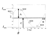
図7は、方向が異なる偏光主軸(Ψi=0°、45°、90°、135°)を有する4種類の偏光子を透過した光の輝度501〜504を示している。ここで、偏光主軸の回転角ψがψiのときにおける観測輝度をIiとする。ただし、「i」は、1以上N以下の整数、「N」はサンプル数とする、図7に示す例では、N=4であるため、i=1、2、3、4となる。図7には、4画素のサンプル(ψi,Ii)に対応する輝度501〜504が示されている。 FIG. 7 shows luminances 501 to 504 of light transmitted through four types of polarizers having polarization main axes (ψi = 0 °, 45 °, 90 °, 135 °) having different directions. Here, it is assumed that the observed luminance when the rotation angle ψ of the polarization main axis is ψ i is I i . However, “i” is an integer from 1 to N, and “N” is the number of samples. In the example shown in FIG. 7, since N = 4, i = 1, 2, 3, 4. FIG. 7 shows luminances 501 to 504 corresponding to the 4-pixel sample (ψi, Ii).
偏光主軸の角度Ψiと輝度501〜504との関係は、正弦関数によって表現される。図7では、輝度501〜504の4点が1本の正弦関数カーブ上に位置するように記載されているが、より多くの観測輝度に基づいて正弦関数カーブを決定した場合、観測輝度の一部が正弦関数カーブ上から僅かに外れる場合もあり得る。
The relationship between the polarization principal axis angle ψi and the luminance values 501 to 504 is expressed by a sine function. In FIG. 7, four points of
なお、本明細書における「偏光情報」とは、輝度の偏光主軸角度に対する依存性を示す正弦関数カーブにおける振幅変調度および位相情報を意味するものとする。 Note that “polarization information” in this specification means amplitude modulation degree and phase information in a sine function curve indicating the dependence of luminance on the polarization principal axis angle.
実際の処理では、図3(a)に示す同一カラー領域301〜304ごとに内部の4個の画素輝度値をサンプルとして、パターン化偏光子の主軸角ψに対する反射光輝度Iを以下のように近似する。

ここで図5に示すようにA、B、Cは定数であり、それぞれ、偏光輝度の変動カーブの振幅、位相、平均値を表現している。(式1)は、以下のように展開できる。
ただし、AおよびBは、それぞれ、以下の(式3)および(式4)で示される。
以下の(式5)を最小にするA、B、Cを求めれば、輝度Iと偏光主軸角Ψとの関係を(式1)の正弦関数によって近似できる。
以上の処理で1つのカラーについて正弦関数近似のA、B、Cの3パラメータが確定する。 With the above processing, the three parameters A, B, and C of the sine function approximation are determined for one color.
こうして、偏光度ρを示す偏光度画像と偏光位相φを示す偏光位相画像が求められる。偏光度ρは、該当画素の光が偏光している程度を表し、偏光位相φは、該当画素の光の部分偏光の主軸角度を表している。なお、偏光の主軸角度は0と180°(π)は同一である。値ρおよびφ(0≦φ≦π)は、それぞれ、以下の(式6)および(式7)によって算出される。
なお、本実施形態の画像処理装置は、偏光度画像ρと偏光位相画像φとを出力しているが、出力する偏光情報は、図7の正弦関数から得られる情報であれば、他の情報の組であってもよい。たとえば、正弦関数の最高輝度Imax、最低輝度Iminの値と、それぞれの値をとる角度Ψmax=φ、Ψminなどの組み合わせを偏光情報として出力してもよい。 Note that the image processing apparatus of the present embodiment outputs the polarization degree image ρ and the polarization phase image φ, but the output polarization information is other information as long as it is information obtained from the sine function of FIG. It may be a pair. For example, a combination of the values of the maximum luminance Imax and the minimum luminance Imin of the sine function and the angles Ψmax = φ, Ψmin taking the respective values may be output as the polarization information.
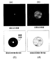
図8は、球体であるプラスチック製ボールの被写体の入力画像である。図9(a)および(b)は、それぞれ、図8の被写体に対する、偏光度画像ρ(x、y)および偏光位相画像φ(x,y)の例を示している。図9の画像は、各画像において、偏光度ρ、偏光位相φが大きいほど、高い明度を示すように表示されている。 FIG. 8 is an input image of a subject of a plastic ball that is a sphere. FIGS. 9A and 9B show examples of the polarization degree image ρ (x, y) and the polarization phase image φ (x, y) for the subject in FIG. 8, respectively. The images in FIG. 9 are displayed such that the higher the degree of polarization ρ and the polarization phase φ in each image, the higher the brightness.
図10(a)および(b)は、図9の画像を説明するための模式図である。偏光度画像ρ(x,y)では、カメラの視線方向とボールの表面法線とが同一になる中心付近から方位7101の向きに画素位置が離れるほど、その画素の偏光度ρは増加する。また、ボールの表面法線がカメラの視線方向に対して90度に近くなるボールの遮蔽エッジ(背景との境界)付近では、偏光度ρが最大になっている。図10(a)では、この偏光度ρを等高線で模式的に表現した。
10A and 10B are schematic diagrams for explaining the image of FIG. In the polarization degree image ρ (x, y), the degree of polarization ρ of the pixel increases as the pixel position moves away from the vicinity of the center where the viewing direction of the camera and the surface normal of the ball are the same in the direction of the
図10(b)の偏光位相画像φ(x,y)では、位相=0度を示す画像の天地方向の垂線に対して偏光位相が180度周期で球体の周囲を反時計回りに矢印7102、7103の向きに単調増加していることがわかる。これら偏光情報画像によれば、偏光度ρと偏光位相φが、被写体の表面法線の2自由度の向きに相当していることがよくわかる。すなわち偏光情報が被写体の形状を推定することが可能になる。
In the polarization phase image φ (x, y) in FIG. 10B, the
なお、本実施形態では、被写体の反射光のうち拡散反射成分の偏光度画像と偏光位相画像を出力としているが、これは鏡面反射成分でもよく、その場合偏光位相φが90°異なるものとなる。 In the present embodiment, the polarization degree image and the polarization phase image of the diffuse reflection component of the reflected light of the subject are output. However, this may be a specular reflection component, in which case the polarization phase φ is 90 ° different. .
また偏光情報としては、(ρ,φ)という組み合わせの他、図5の正弦関数から得られる情報であれば、他の情報の組であってもよく、その情報から生成される画像でもよい。たとえば偏光情報から被写体の拡散反射成分と鏡面反射成分を分離することが応用面で重要である。これを本発明で実行するには、鏡面反射領域の偏光に対してρ(x,y)に一定の比率を乗じて原画像から減算すればよい。このようにして生成された画像の例を図11(a)から(d)に示す。 In addition to the combination of (ρ, φ), the polarization information may be a combination of other information as long as it is information obtained from the sine function of FIG. 5 or an image generated from the information. For example, it is important in application to separate a diffuse reflection component and a specular reflection component of a subject from polarization information. In order to execute this in the present invention, it is only necessary to multiply ρ (x, y) by a certain ratio with respect to the polarization in the specular reflection region and subtract it from the original image. Examples of images generated in this way are shown in FIGS.
図1に示すカラー情報処理部102は、カラー偏光取得部101から出力される情報を用いて、カラー輝度を計算する。偏光子を透過した光の輝度は、偏光子に入射する前の光が有する本来の輝度とは異なる。非偏光照明の場合、理論的には、偏光のすべての偏光主軸における観測輝度を平均化した値が偏光子に入射する前の光が有する本来の輝度に相当する。偏光画素R1における観測輝度をIR1と表現すると、以下の(式8)に基づいて、カラー輝度を算出することができる。
各偏光画素における輝度を得ることにより、通常のカラーモザイク画像を生成できる。モザイク画像に基づいて各画素でRGB画素値を有するカラー画像へ変換することにより、カラー画像Imが生成される。このような変換は、例えばベイヤーモザイクの補間方法などの公知の補間技術を用いて実現される。 A normal color mosaic image can be generated by obtaining the luminance in each polarization pixel. A color image Im is generated by converting each pixel into a color image having RGB pixel values based on the mosaic image. Such conversion is realized by using a known interpolation technique such as a Bayer mosaic interpolation method.
カラー画像lm、偏光度画像ρ、偏光位相画像φの各々における各画素の輝度および偏光情報は、図3(b)に示す4つの偏光画素を用いて得られるため、個々の輝度および偏光情報は、図3(b)に示す4つの偏光画素の中心に位置する仮想画素点305における値を示していると考えることができる。従って、カラー画像および偏光画像の解像度は、いずれも、撮像素子の解像度の縦1/2×横1/2に低下する。
Since the luminance and polarization information of each pixel in each of the color image lm, the polarization degree image ρ, and the polarization phase image φ are obtained using the four polarization pixels shown in FIG. 3B, the individual luminance and polarization information is It can be considered that the value at the
しかしながら本実施形態では、図3や図4に示すように、1色のカラーモザイク画素内に複数の微細な偏光子が存在するため、微細画像にて4分割しないカラーモザイク画素を用いる場合の解像度と比較した場合には同等の解像度である。 However, in this embodiment, as shown in FIG. 3 and FIG. 4, since there are a plurality of fine polarizers in one color mosaic pixel, the resolution when using color mosaic pixels that are not divided into four in a fine image is used. Is equivalent to the resolution.
次に、図12を参照しながら、図1におけるカラー情報処理部102および偏光情報処理部103の動作を説明する。
Next, operations of the color
まず、最初にカラー偏光取得部101にてカラー動画像と偏光情報画像を同時にリアルタイムに取得する。ステップS801〜S803において、カラー動画像のR、G、Bの各画素における複数の偏光輝度の観測値を取得する。ステップS801〜S803の順序は任意であり、並列的に実行されてもよい。具体的には、R、G、Bのカラーモザイク画素内で4種類の偏光輝度を取得する。偏光輝度を示す信号は、偏光情報処理部103に送られ、ステップS804〜S808において、以下のように処理される。
First, the color
すなわち、ステップS804〜S806の各々において、R画素、G画素、B画素の各々から得られる変動輝度に基づいて、正弦関数パラメータを算出する。正弦関数パラメータは、前述の(式1)におけるA、B、Cで規定される。ステップS804〜S806の処理も、互いに独立しているため、任意の順序で行うことがであり、並列的に実行されてもよい。 That is, in each of steps S804 to S806, a sine function parameter is calculated based on the varying luminance obtained from each of the R pixel, G pixel, and B pixel. The sine function parameter is defined by A, B, and C in (Equation 1) described above. Since the processes of steps S804 to S806 are also independent of each other, they can be performed in an arbitrary order and may be executed in parallel.
その後、図1のカラー情報処理部102により、ステップS808の処理が実行される。具体的には、前述の(式8)を用いて、R、G、Bの平均輝度が求められ、カラー輝度画像I(x,y)が生成される。
Thereafter, the color
本実施形態の画像処理装置によれば、以下に示す従来技術の課題1)、2)を解決することができる。
1)カラー分離特性と偏光特性の干渉
2)カラー輝度取得と偏光情報取得の両立が困難
According to the image processing apparatus of the present embodiment, the following problems 1) and 2) of the prior art can be solved.
1) Interference between color separation characteristics and polarization characteristics 2) Difficult to obtain both color luminance and polarization information
すなわち、課題1)について、本実施形態によれば、R、G、Bのカラー別に各波長の狭い帯域で偏光特性が動作する偏光素子を独立に利用して干渉をなくすことができる。また、課題2)について、本実施形態によれば、1つのカラー分離系に偏光情報分離系を完全に包含させ1種類のカラー毎に偏光情報を得ることを可能にする。 That is, regarding the problem 1), according to the present embodiment, it is possible to eliminate interference by independently using polarizing elements that operate in a narrow band of each wavelength for each of R, G, and B colors. As for the problem 2), according to the present embodiment, the polarization information separation system is completely included in one color separation system, and polarization information can be obtained for each type of color.
なお、本実施形態では、パターン化偏光子にフォトニック結晶を用いているが、偏光素子は、フィルム型の偏光素子、ワイヤーグリッド型、その他の原理による偏光素子であってもよい。 In this embodiment, a photonic crystal is used for the patterned polarizer, but the polarizing element may be a film-type polarizing element, a wire grid type, or a polarizing element based on other principles.
(第2の実施形態)
以下、本発明による画像処理装置の第2の実施形態を説明する。
(Second Embodiment)
Hereinafter, a second embodiment of the image processing apparatus according to the present invention will be described.
第1の実施形態では、単板カラー撮像系を使用していたため、本来の撮像素子が有している解像度よりも、解像度が低下していた。このような解像度の低下は、カラーを光線の入射位置に応じて分離するカラーモザイクフィルタに起因している。本実施形態では、カラーモザイクフィルタに代えて、同一領域に入射した光を波長帯域に応じて異なる色に分離する色分解素子を用い、それによって第1の実施形態よりも解像度を高めることができる。 In the first embodiment, since a single-plate color imaging system is used, the resolution is lower than the resolution of the original imaging device. Such a decrease in resolution is caused by a color mosaic filter that separates colors according to the incident positions of light rays. In this embodiment, instead of the color mosaic filter, a color separation element that separates the light incident on the same region into different colors according to the wavelength band is used, and thereby, the resolution can be improved as compared with the first embodiment. .
本実施形態の基本的構成も、図1のブロック図で示されるため、ここでも適宜、図1を参照する。本実施形態の画像処理装置も、被写体からリアルタイムにカラー画像情報を取得すると同時に偏光画像情報を取得し、2種類の偏光画像(偏光度画像、および偏光位相画像)として出力する。レンズ100aおよび絞り100bを通った光は、カラー偏光取得部101に入射し、この入射光から、カラー偏光取得部101がカラー動画像情報および偏光画像情報の両方をリアルタイムに取得する。後述するように、本実施形態のカラー偏光取得部101は、色分解プリズムを備えている。カラー偏光取得部101からは、カラー動画像情報およびと偏光情報画像情報を示す信号が出力され、それぞれ、カラー情報処理部102および偏光情報処理部103に送られる。カラー情報処理部102およびと偏光情報処理部103は、上記信号に対して各種の処理を施し、カラー画像lm、偏光度画像ρ、偏光位相画像φを出力する。
Since the basic configuration of the present embodiment is also shown in the block diagram of FIG. 1, FIG. The image processing apparatus according to the present embodiment also acquires color image information from a subject in real time and simultaneously acquires polarization image information, and outputs it as two types of polarization images (polarization degree image and polarization phase image). The light passing through the
まず、図13Aおよび図13Bを参照しながら、色分解(ダイクロック)プリズムを用いたカラー偏光取得部101の最も単純な構成例を説明する。図13Aに例示したカラー偏光取得部101は、Rのパターン化偏光子が付加された撮像素子1201、Rのパターン化偏光子が付加された撮像素子1202、Rのパターン化偏光子が付加された撮像素子1203を備えており、色分解プリズムによって分立されたR、G、Bの光は、それぞれ、撮像素子1201、1202、1203に入射する。
First, the simplest configuration example of the color
図13Bは、撮像素子1201、1202、1203にそれぞれ付加された3種類のパターン化偏光子の配列を示す図である。この例では、R、G、Bのパターン化偏光子の各々において、透過偏光面が0度、45度、90度、135度という組み合わせのパターンが繰り返されている。また、偏光の波長特性は、図5に示す特性を満足する。
FIG. 13B is a diagram showing an array of three types of patterned polarizers added to the
図13Bに示す配列の例では、4画素で1セットが構成されるため、図3を参照しながら説明したように、RGBの各色ごとに偏光情報を取得することができる。また、4画素の輝度を平均することにより、カラー画像も取得できる。 In the example of the arrangement shown in FIG. 13B, since one set is formed by four pixels, polarization information can be acquired for each color of RGB as described with reference to FIG. A color image can also be obtained by averaging the luminance of the four pixels.
しかしながら、上述の構成例では、人間の視覚特性に重要なG画素の空間解像度が低下するという課題が残る。以下、図13Cを参照しながら、この課題を解決したカラー偏光取得部101の構成を説明する。
However, the above configuration example still has a problem that the spatial resolution of G pixels, which is important for human visual characteristics, is reduced. Hereinafter, the configuration of the color
本実施形態のカラー偏光取得部101は、色分解プリズム900と、R、G、B専用の撮像素子901、902、903と、RおよびB用のパターン化偏光子904、905とを備えている。パターン化偏光子904,905における微小な各偏向素子単位が設置された画素を、以下、偏光画素と称する。
The color
色分解プリズム900を使用することにより、被写体の各画素からR、G、Bの画像情報を取得できるため、解像度が向上する。また、本実施形態では、パターン化偏光子をR用撮像素子901およびB用撮像素子903の前に配置し、G用撮像素子902の前には配置していない。このため、G画像の解像度を、R画像やB画像の解像度よりも高めることができる。G光は、R、B光に比べて人間の視覚感度が最も高い色であるため、G画像を高解像度化することにより、解像度増加の視覚効果を効率的に得ることができる。
By using the
図14(a)から(c)は、RおよびB用のパターン化偏光子904、905と、対応するG用の画素とを示す図である。G用撮像素子902には、パターン化偏光子が設置されない。B用のパターン化偏光子905、およびR用パターン化偏光子904は、ぞれぞれ、図5(a)および図5(c)に示すように、B光およびR光の波長帯域において偏光特性を有している。R用パターン化偏光子904の偏光主軸は、以下の通りである。
FIGS. 14A to 14C are diagrams showing R and B patterned polarizers 904 and 905 and corresponding G pixels. The
一方、B用パターン化偏光子905の偏光主軸は、以下の通りである。
On the other hand, the polarization main axes of the patterned polarizer for
4種類の偏光画素から得られる偏光情報を表現する画素は、中心画素1001である。
A pixel expressing polarization information obtained from the four types of polarization pixels is a
パターン化偏光子904、905における配列の特徴は、以下の通りである。
(1)2×2画素からなるブロック内において、偏光主軸の異なる4つの偏光画素が隣接している。
(2)上記の各ブロック内において、隣接する偏光画素の偏光主軸は相互に45°異なる。
(3)偏光画素R1〜R4、B5〜B9の偏光主軸は、0°から180°までの間に等間隔(22.5°)で存在している。
The characteristics of the arrangement in the patterned
(1) In a block composed of 2 × 2 pixels, four polarizing pixels having different polarization main axes are adjacent to each other.
(2) In each of the above blocks, the polarization main axes of adjacent polarization pixels differ from each other by 45 °.
(3) The polarization main axes of the polarization pixels R1 to R4 and B5 to B9 exist at equal intervals (22.5 °) between 0 ° and 180 °.
これらの性質を満足すれば、偏光画素R1〜R4および偏光画素B5〜B9の配列順序は任意である。たとえば、図15(a)に示すよう順序で配列されていても良い。図15(a)では、偏光画素R1〜R4および偏光画素B5〜B8の他の配置例が示されている。なお、図15(b)の例では、R画素として偏光画素R5〜R8が配列され、B画素として偏光画素R1〜R4が配置されている。ここで、偏光画素に付与される参照符号1〜9により、以下に示すように偏光主軸の角度が規定されている。
If these properties are satisfied, the arrangement order of the polarization pixels R1 to R4 and the polarization pixels B5 to B9 is arbitrary. For example, they may be arranged in the order shown in FIG. FIG. 15A shows another arrangement example of the polarization pixels R1 to R4 and the polarization pixels B5 to B8. In the example of FIG. 15B, polarizing pixels R5 to R8 are arranged as R pixels, and polarizing pixels R1 to R4 are arranged as B pixels. Here, the
このようなパターン化偏光子は、例えば非特許文献2に記載されたフォトニック結晶を用いて作製することができる。 Such a patterned polarizer can be produced using, for example, a photonic crystal described in Non-Patent Document 2.
本実施形態では、異なる8つの方位を有する偏光主軸が画素Rおよび画素Bに分散して配置されているが、これらの画素から得られる輝度情報を統合して処理することにより、合計8点の異なる偏光角度における輝度情報が得られる。以下、この統合化処理の方法を説明する。 In this embodiment, the polarization main axes having eight different orientations are distributed and arranged in the pixel R and the pixel B. By integrating and processing the luminance information obtained from these pixels, a total of eight points can be obtained. Luminance information at different polarization angles is obtained. Hereinafter, a method of this integration process will be described.
図16は、図13Cに示す構成のカラー偏光取得部101を用いて被写体を観測した場合に得られる輝度の偏光主軸方向依存性を示すグラフである。自然界にある被写体は様々である。しかし、金属以外の誘電体を想定した場合、照明が被写体に照射されて得られる反射光の性質は、フレネル反射の理論で記述される。そのため、鏡面反射および拡散反射のいずれの場合においても、その偏光の性質は、R、G、Bの波長帯域で大きく変化はしない。すなわち、R、G、Bの輝度変動を示す正弦関数は、すべて、周期180°であり、等しい位相で変化する。したがって、(式6)の偏光度ρの関係式を用いて、3種類の輝度変動は、(式9)に示す式で表現できる。
屈折率η、光の入射角、および出射角は、R、G、Bの間で実質的に一定であるため、偏光度ρもR、G、Bの間で一定となる。このため、(式9)における3種類の正弦関数の変動部分は、R、G、Bに共通となる。 Since the refractive index η, the incident angle of light, and the outgoing angle are substantially constant between R, G, and B, the degree of polarization ρ is also constant between R, G, and B. For this reason, the fluctuation portions of the three types of sine functions in (Equation 9) are common to R, G, and B.
図16に示すカーブ1101、1102、1103は、それぞれ、R、G、Bの輝度変化を示している。また、ライン1104、1105、1106は、それぞれ、R、G、Bの平均輝度を示す。
本実施形態では、図13Cに示す構成を有しているため、G撮像素子902にはパターン化偏光子が設置されていない。このため、Gの輝度変動観測値は存在せず、カーブ1102は、あくまで理論式から求められる曲線にすぎない。しかし、ライン1105によって示されるGの輝度平均値は理論値ではなく、図14に示す画素G00から画素G11の4つ画素の輝度の平均値である。この平均値は、点1001における輝度値として観測される。図16における点1107は、Gの輝度平均値が実測値であることを示すため、グラフ中に記載したものである。
In the present embodiment, the
白点で示される輝度IR1〜IR4は、図14に示すR用パターン化偏光子904の4画素での観測輝度を示し、黒点で示される観測輝度IR5〜IR8は、B用パターン化偏光子905の4画素での観測輝度を示す。すなわち、4方向の偏光情報は、RおよびBの2種のカラー成分に分散している。本発明者らの実験によれば、偏光主軸が4方向の輝度測定値のみに基づいて1本の輝度変化カーブを決定すると、ノイズが多くなる場合があり、輝度変化カーブを高い精度で決定することが容易ではない。しかし、本実施形態のように偏光主軸が8方向の輝度測定値を用いると、ノイズが低減されるため、輝度変化カーブを高い精度で決定することができる。異なる色について得られる輝度測定値に基づいて1つの輝度変化カーブを決定することを「統合化」と称することにする。統合化のためには、測定された輝度IR1〜IR4、IB5〜IB8に対して、(式10)に示す変換を実施して補正を行う必要がある。補正後の輝度値を用いて統合化することにより、正弦関数カーブを決定する。
図17は、この統合化の結果を示している。本来は存在しない仮想的なGの輝度変動カーブに合致するようにRおよびBの輝度観測値を補正して統合化している。輝度I’R1〜I’R4、I’B5〜I’B8は、平均輝度がライン1105となる正弦関数カーブ上に位置する。これら8点の輝度補正値について、(式5)に示す最小2乗誤差が最小となる正弦関数カーブを算出する。
FIG. 17 shows the result of this integration. The luminance observation values of R and B are corrected and integrated so as to match a virtual G luminance fluctuation curve that does not exist originally. The luminances I ′ R1 to I ′ R4 and I ′ B5 to I ′ B8 are located on a sine function curve where the average luminance is a
ここでは、Gについて仮想的な輝度変化カーブを設定し、RおよびBの輝度がGの輝度変化カーブ上に位置するようにして統合化を行っているが、G以外の色の輝度カーブ上に他の色の輝度が位置するように統合化を行っても良い。 Here, a virtual luminance change curve is set for G, and integration is performed such that the luminances of R and B are positioned on the luminance change curve of G. However, on the luminance curves of colors other than G, Integration may be performed so that the luminances of other colors are located.
図18は、Bの輝度をRの輝度にあわせこんだ統合化の例を示す。この場合、Bの輝度IB5〜IB8からBの輝度補正値I”B5〜I”B8を、以下の(式11)に基づいて算出する。
RおよびBの輝度値は、それぞれ、理論的に周期180度の正弦関数カーブ上にあることがわかっている。このため、RおよびBの輝度値は、それぞれ、同一カラーで位相(偏光主軸の方向)が等間隔でずれた4点における輝度の観測値を平均した値によって与えられる。すなわち、RおよびBの輝度値は、以下の(式12)によって表される。
一方、Gの輝度値は、G用撮像素子902の前に偏光子が存在しないため、輝度の観測値に等しい。
On the other hand, the luminance value of G is equal to the observed luminance value because there is no polarizer in front of the
本実施形態によれば、Gについては高解像度画像が得られ、RおよびBについては、Gに比べて解像度が1/4に低下した画像が得られることになる。しかし、人間の視感度に最も影響を与えるGの解像度が高いため、全体して、人間の目に感じる画質はあまり劣化しないと期待できる。 According to the present embodiment, a high-resolution image is obtained for G, and for R and B, an image with a resolution reduced to ¼ compared to G is obtained. However, since the resolution of G that most affects human visual sensitivity is high, it can be expected that the image quality felt by human eyes as a whole will not deteriorate much.
本実施形態においては色分解プリズムを使うことにより解像度度が向上することを述べたが、色分解においてカラーモザイクフィルタのように光吸収に起因するロスを発生しないという利点もある。概算でカラーモザイクフィルタに比較して約3倍の光量を有効に使うことができるため、感度向上も同時に達成される。 In the present embodiment, it has been described that the resolution degree is improved by using the color separation prism. However, there is an advantage that no loss due to light absorption occurs in the color separation unlike the color mosaic filter. In general, the amount of light that is approximately three times that of the color mosaic filter can be effectively used, so that sensitivity can be improved at the same time.
図19は、本実施形態の動作を図1における画像処理装置に対応させて説明するための図である。 FIG. 19 is a diagram for explaining the operation of the present embodiment in correspondence with the image processing apparatus in FIG.
まず、最初にカラー偏光取得部101にてカラー動画像と偏光情報画像を同時にリアルタイムに取得する。ステップS1301〜S1303において、カラー動画像のR、G、Bの各画素における複数の偏光輝度の観測値を取得する。ステップS1301〜S1303の順序は任意であり、並列的に実行されてもよい。Gについては高解像度にて実際の輝度が取得されるが、RとBについては低解像度で偏光子を透過した輝度のみが取得される。
First, the color
両者の解像度が異なるため偏光情報画像としては、図14の位置1001において、RおよびBの偏光情報を統合化する。ステップS1304において、(式10)に従い、補正係数Krrを用いてR画像の異なる偏光輝度をGに統合する。同様に、ステップS1305において、補正係数Kbbを用いてB画像の異なる偏光輝度をGに統合する。これらのステップS1304〜S1306の順番も任意であり、並列に実行されてもよい。
Since the resolutions of the two are different, the polarization information images of R and B are integrated at a
ステップS1306では、図14の位置1001における偏光度画像ρ(x,y)および偏光位相画像φ(x,y)が生成される。
In step S1306, a polarization degree image ρ (x, y) and a polarization phase image φ (x, y) at the
図1に示すカラー情報処理部102では、(式11)に基づいて、RおよびBの位置1001に相当する低解像度画像を生成し(ステップS1307)、Gの高解像度画像と画素位置を合わせてカラー輝度画像Im(x,y)が生成される(S1308)。
The color
本実施形態の画像処理装置によれば、以下に示す従来技術の課題1)、2)を解決することができる。
1)カラー分離特性と偏光特性の干渉
2)カラー輝度取得と偏光情報取得の両立が困難であること
According to the image processing apparatus of the present embodiment, the following problems 1) and 2) of the prior art can be solved.
1) Interference between color separation characteristics and polarization characteristics 2) It is difficult to achieve both color luminance acquisition and polarization information acquisition.
すなわち、課題1)について、本実施形態によれば、R、G、Bのカラー別に各波長の狭い帯域で偏光特性が動作する偏光素子を独立に利用して干渉をなくすことができる。また、課題2)について、本実施形態では、色分解プリズムによるR、G、B分離を行ない、Gは通常のカラー輝度画素とし、RおよびBを偏光画素とする。不足する偏光角度情報は、RおよびBの観測輝度値に一定の補正係数を乗じて統合化することによって求めている。これにより実質的に6種類の偏光角度情報を得るようにしてカラー輝度と偏光情報の取得の両立を実現できる。 That is, regarding the problem 1), according to the present embodiment, it is possible to eliminate interference by independently using polarizing elements that operate in a narrow band of each wavelength for each of R, G, and B colors. As for the problem 2), in this embodiment, R, G, and B are separated by the color separation prism, G is a normal color luminance pixel, and R and B are polarization pixels. The insufficient polarization angle information is obtained by multiplying the observed luminance values of R and B by a certain correction coefficient and integrating them. Accordingly, it is possible to obtain both color luminance and polarization information by substantially obtaining six types of polarization angle information.
なお、本実施形態でも、パターン化偏光子にフォトニック結晶を用いているが、偏光素子は、フィルム型の偏光素子、ワイヤーグリッド型、その他の原理による偏光素子であってもよい。 In this embodiment as well, a photonic crystal is used for the patterned polarizer, but the polarizing element may be a film-type polarizing element, a wire grid type, or a polarizing element based on other principles.
(第3の実施形態)
以下、本発明による画像処理装置の第3の実施形態を説明する。
(Third embodiment)
Hereinafter, a third embodiment of the image processing apparatus according to the present invention will be described.
第2の実施形態では、パターン化偏光子を使用していたため、特にRおよびBの解像度が本来の撮像素子における解像度よりも低下していた。本実施形態では、RおよびBの解像度低下を回避できる。 In the second embodiment, since the patterned polarizer is used, the resolutions of R and B are particularly lower than the resolution of the original image sensor. In this embodiment, it is possible to avoid a decrease in the resolution of R and B.
本実施形態の基本的構成も、図1のブロック図で示されるため、ここでも適宜、図1を参照する。本実施形態の画像処理装置も、被写体からリアルタイムにカラー画像情報を取得すると同時に偏光画像情報を取得し、2種類の偏光画像(偏光度画像、および偏光位相画像)として出力する。レンズ100aおよび絞り100bを通った光は、カラー偏光取得部101に入射し、この入射光から、カラー偏光取得部101がカラー動画像情報および偏光画像情報の両方をリアルタイムに取得する。後述するように、本実施形態のカラー偏光取得部101は、色分解プリズムを備えている。カラー偏光取得部101からは、カラー動画像情報およびと偏光情報画像情報を示す信号が出力され、それぞれ、カラー情報処理部102および偏光情報処理部103に送られる。カラー情報処理部102およびと偏光情報処理部103は、上記信号に対して各種の処理を施し、カラー画像lm、偏光度画像ρ、偏光位相画像φを出力する。
Since the basic configuration of the present embodiment is also shown in the block diagram of FIG. 1, FIG. The image processing apparatus according to the present embodiment also acquires color image information from a subject in real time and simultaneously acquires polarization image information, and outputs it as two types of polarization images (polarization degree image and polarization phase image). The light passing through the
図20を参照して、本実施形態におけるカラー偏光取得部101の構成を説明する。
With reference to FIG. 20, the structure of the color
図20は、本実施形態におけるカラー偏光取得部101の構成を示す図である。このカラー偏光取得部101は、色分解プリズム900と、R、G、B用の偏光ビームスプリッタ1407、1408、1409を備えている。R用の偏光ビームスプリッタ1408で分離されたR光は、それぞれ、P偏光成分を取得する撮像素子1401およびS偏光成分を取得する撮像素子1402に入射する。同様に、G用の偏光ビームスプリッタ1407で分離されたG光は、それぞれ、P偏光成分を取得する撮像素子1403、およびS偏光成分を取得する撮像素子1404に入射し、B用の偏光ビームスプリッタ1409で分離されたB光は、それぞれ、P偏光成分を取得する撮像素子1406およびS偏光成分を取得する撮像素子1405に入射する。
FIG. 20 is a diagram illustrating a configuration of the color
本実施形態では、パターン化偏光子の代わりに、偏光ビームスプリッタを用いて偏光情報を取得しているため、解像度の低下が無く、また、視覚感度の高いG成分からも偏光情報を取得できる。 In this embodiment, since polarization information is acquired using a polarization beam splitter instead of a patterned polarizer, the resolution is not reduced, and polarization information can be acquired from a G component with high visual sensitivity.
なお、「偏光ビームスプリッタ」は、入射光をその偏光成分によって分離するフィルタであり、入射光線の光軸に対して45°の角度で傾斜したフィルタ面が、P偏光成分を透過、S偏光成分を反射する。偏光ビームスプリッタの動作波長域は、パターン化偏光子の場合と同様に、可視光全域にわたるものではなく、比較的狭い。本実施形態では、R用ビームスプリッタ1407と、G用ビームスプリッタ1408と、B用のビームスプリッタ1408は、いずれも、図5のように色分解プリズムが3色分解するRGB波長域に各々の動作波長域が一致するように設計されている。
The “polarization beam splitter” is a filter that separates incident light by its polarization component, and a filter surface inclined at an angle of 45 ° with respect to the optical axis of the incident light beam transmits the P-polarization component and S-polarization component. To reflect. The operating wavelength range of the polarizing beam splitter is not limited to the entire visible light region as in the case of the patterned polarizer, but is relatively narrow. In the present embodiment, the
通常、偏光ビームスプリッタでは、P成分とS成分という直交する2方向の偏光からしか偏光情報が得られない。しかし、本実施形態では、R用の偏光ビームスプリッタ1407およびB用の偏光ビームスプリッタ1409を、それぞれの光軸まわりに所定の角度だけ回転させて固定することにより、複数の偏光角度における偏光情報を得ることができる。図20に示す、R用およびB用の撮像素子1407、1409の記載は、その回転角度が若干不明瞭であるが、図21は、回転角度をより詳しく説明するための図である。図20は、R、G、B用の各ビームスプリッタ1407〜1409が、各々の光軸まわりに回転して固定され、かつ撮像素子もそれに対応して設置されている構成を示す図である。
Usually, in a polarization beam splitter, polarization information can be obtained only from polarized light in two directions, ie, a P component and an S component. However, in the present embodiment, the polarization information at a plurality of polarization angles is fixed by rotating the
図21に示されるように、R用の偏光ビームスプリッタ1407は+30°、B用の偏光ビームスプリッタ1409は−30°、G用の偏光ビームスプリッタ1408に対して回転している。このため、Gの偏光は0°および90°、Rの偏光は30°および120°、Bの偏光は60°および150°の角度だけ回転した偏光主軸における観測を行うことができる。すなわち、撮像素子1401によって、Rp(R光のP偏光成分)が、撮像素子1402によってRs(R光のS偏光成分)が取得される。同様に撮像素子1403によって、Gp(G光のP偏光成分)が、撮像素子1404によってGs(G光のS偏光成分)が取得される。また同様に、撮像素子1405によって、Bs(G光のS偏光成分)が、撮像素子1406によってBp(B光のP偏光成分)が取得される。
As shown in FIG. 21, the R
図22は、図20および図21に示すビームスプリッタによって観測される偏光の主軸角度を同一の角度座標上にて示す図である。図22における符号は、図20、図21の対応する撮像素子の参照符合である。輝度が観測される偏光の偏光主軸は、0°から180°まで、Gp、Rp、Bs、Gs、Rs、Bpの順に30°ずつ回転している。 FIG. 22 is a diagram showing the principal axis angles of polarized light observed by the beam splitter shown in FIGS. 20 and 21 on the same angle coordinates. The reference numerals in FIG. 22 are reference numerals of the corresponding image pickup elements in FIGS. The polarization main axis of the polarized light whose luminance is observed is rotated by 30 ° in the order of Gp, Rp, Bs, Gs, Rs, and Bp from 0 ° to 180 °.
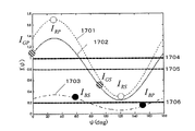
図23は、Rの輝度変化カーブ1701、Gの輝度変化カーブ1702、Bの輝度変化カーブ1703と、R、G、Bの平均輝度1704、1705、1706を示している。撮像素子1403、1404で観測される輝度IGP、IGSは、斜線のサークルで示されている。また、撮像素子1401、1402で観測される輝度IRP、IRSは、白いサークルで示され、撮像素子1405、1406で観測される輝度IBS、IBPは、黒いサークルで示されている。すなわち、PおよびS偏光の直交する偏光主軸に関する偏光情報は、R、G、およびBの3種のカラー成分に分散している。理論上、2点の輝度値から1本の正弦関数カーブを決定することは不可能であるので、カラー別に正弦関数カーブを決定することはできない。本実施形態では、各カラーについて観測される輝度値を統合化することにより、正弦関数カーブを決定している。統合化のため、第2の実施形態について説明したように、得られた6個の輝度IRP〜IBSに対して、(式13)の変換を実施する。すなわち、補正係数Kr、Kbを用いてRおよびBの輝度をGの輝度に合わせ込む補正を行う。補正を行った上で統合した輝度のサンプルを用いて、正弦関数カーブの決定を実施する。
図24は、上記の統合化によって得られた正弦関数カーブを示している。RおよびBの観測値は、統合化され、Gの輝度変動カーブ上に位置している。こうして得られる6点の輝度について、(式5)の最小2乗誤差最適化を行うことにより正弦関数カーブを決定すれば、偏光情報を高い精度で求めることができる。 FIG. 24 shows a sine function curve obtained by the above integration. The observed values of R and B are integrated and located on the G luminance fluctuation curve. If the sine function curve is determined by performing the least square error optimization of (Equation 5) for the luminance of the six points thus obtained, the polarization information can be obtained with high accuracy.
カラー輝度の正弦関数カーブの周期は、周期180°であるため、同じカラーで位相が90°異なる2点の観測値を平均すれば、そのカラーの輝度値が求められる。
このように本実施形態では、偏光ビームスプリッタを用いるため、RおよびBの解像度低下を回避できるのみならず偏光フィルタの光吸収による光量のロスが無くなり、感度の向上を達成することができる。 As described above, in this embodiment, since the polarization beam splitter is used, not only the resolution reduction of R and B can be avoided, but also the loss of light amount due to the light absorption of the polarization filter is eliminated, and the improvement in sensitivity can be achieved.
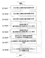
図25は、図1における画像処理装置に対応してその動作を説明する図であり、カラー偏光取得部については第3の実施形態について述べるものとする。最初にカラー偏光取得部101にてカラー動画像と偏光情報画像を同時にリアルタイムに取得され、その信号は偏光情報処理部103に送られ以下のように処理される。まずS1901〜S1903のステップで101にて撮像されたR、G、Bの各画像の異なる複数の偏光輝度の観測値を取得する。すなわち、R、G、B画像で各々P偏光とS偏光という2種類の偏光輝度が取得されるため、画像としてはR、G、B画像が各々2枚取得されることとなる。このS1901からS1903の処理順番は任意であり並列に実行されてもよい。
FIG. 25 is a diagram for explaining the operation corresponding to the image processing apparatus in FIG. 1, and the color polarization acquisition unit is described in the third embodiment. First, a color moving image and a polarization information image are simultaneously acquired in real time by the color
次にS1904において、補正係数Krを用いてR画像の異なる偏光輝度をGに統合し、同様にS1904において補正係数Kbを用いてB画像の異なる偏光輝度をGに統合する。この処理は、(式13)の処理を用いて実行され、結局R、G、Bで合計6枚の画像に統合される。このS1904とS1905の処理の順番も任意であり並列に実行されてもよい。次に、S1906において、これらの画像を使って画素毎に(式5)を用いて正弦関数、すなわち、パラメータA、B、Cを決定する。最後にS1907にて、(式6)を使って偏光度画像ρ(x、y)が生成される。 In step S1904, the different polarization luminances of the R image are integrated into G using the correction coefficient Kr. Similarly, in step S1904, the different polarization luminances of the B image are integrated into G using the correction coefficient Kb. This process is executed using the process of (Equation 13), and is eventually integrated into a total of 6 images of R, G, and B. The order of the processing of S1904 and S1905 is arbitrary and may be executed in parallel. In step S1906, a sine function, that is, parameters A, B, and C are determined for each pixel using these images using (Equation 5). Finally, in S1907, a polarization degree image ρ (x, y) is generated using (Expression 6).
カラー情報処理部102では、R、G、B画像がP偏光とS偏光の2枚取得された後、これらから、(式14)を用いてR、G、Bの平均輝度を求めてカラー輝度画像I(x,y)が生成される。
In the color
本発明の画像処理装置は、特別な投光装置などを用いなくても被写体からの偏光情報を取得できるため、各種デジタルスチルカメラ、デジタルムービーカメラ、監視カメラなどに適用可能である。また、今後のカメラの小型化に際して不足すると思われる画像輝度情報に対し、偏光情報から算出される表面の形状情報などを用いて加工処理を行うことが可能になる。 The image processing apparatus of the present invention can be applied to various digital still cameras, digital movie cameras, surveillance cameras, and the like because it can acquire polarization information from a subject without using a special projector. Further, it is possible to perform processing using image shape information calculated from polarization information for image luminance information that is considered to be insufficient in future camera miniaturization.
100a レンズ
100b 絞り
101 カラー偏光取得部
102 偏光情報処理部
103 カラー情報処理部
Claims (11)
同一色画素内の複数の偏光子単位を透過した光の輝度と前記偏光子単位の透過偏波面の角度との関係を正弦関数で近似する偏光情報処理部と、
同一色画素内の複数の偏光子単位を透過した光の輝度を平均化することによって平均カラー輝度情報を取得するカラー情報処理部と、
を備える画像処理装置。A single-plate color imaging device having a color mosaic filter, and a color polarization acquisition unit having a patterned polarizer in which polarizer units having transmission polarization planes of different angles are arranged adjacent to each other in the same color pixel of the color mosaic filter When,
A polarization information processing unit that approximates the relationship between the luminance of light transmitted through a plurality of polarizer units in the same color pixel and the angle of the transmission polarization plane of the polarizer units by a sine function;
A color information processing unit that acquires average color luminance information by averaging the luminance of light transmitted through a plurality of polarizer units in the same color pixel;
An image processing apparatus comprising:
前記複数の撮像素子の出力に基づいて偏光情報を得る偏光情報処理部と、
前記複数の撮像素子の出力に基づいて平均カラー輝度情報を得るカラー情報処理部と、
を備え、
前記複数の撮像素子は、前記分解された異なる色に含まれる第1の色の光から高解像度単色画像を取得する少なくとも1つの高解像度撮像素子と、前記分解された異なる色に含まれる第2の色の光から低解像度画像を取得する少なくとも1つの低解像度撮像素子とを有し、
前記低解像度撮像素子は、異なる方向に透過偏波面を有する複数の偏光子単位が隣接して配列されたパターン化偏光子を有しており、
前記偏光情報処理部は、前記複数の偏光子単位を透過した光の輝度を統合して前記偏光情報を取得する、画像処理装置。A color polarization acquisition unit having a color separation element that separates incident light into a plurality of different colors, and a plurality of imaging elements that each receive light of different colors separated by the color separation element;
A polarization information processing unit for obtaining polarization information based on outputs of the plurality of image sensors;
A color information processing unit for obtaining average color luminance information based on outputs of the plurality of image sensors;
With
The plurality of imaging elements include at least one high-resolution imaging element that acquires a high-resolution single-color image from light of a first color included in the separated different colors, and a second included in the separated different colors. At least one low-resolution image sensor that acquires a low-resolution image from light of
The low-resolution imaging device has a patterned polarizer in which a plurality of polarizer units having transmission polarization planes in different directions are arranged adjacent to each other,
The polarization information processing unit is an image processing device that acquires the polarization information by integrating the luminance of light transmitted through the plurality of polarizer units.
前記高解像度単色素子は、Gの光を受ける請求項2に記載の画像処理装置。The color separation element decomposes incident light into R, G, and B light,
The image processing apparatus according to claim 2, wherein the high-resolution monochromatic element receives G light.
複数の低解像度撮像素子に対応する複数のパターン化偏光素子は、全体として、透過偏波面の角度がθ°だけ異なる(180/θ)種類の偏光子単位を有している請求項2に記載の画像処理装置。The number of the low resolution imaging elements is plural,
The plurality of patterned polarizing elements corresponding to the plurality of low-resolution imaging elements as a whole have (180 / θ) types of polarizer units in which the angle of the transmission polarization plane differs by θ °. Image processing apparatus.
前記複数の撮像素子の出力に基づいて偏光情報を得る偏光情報処理部と、
前記複数の撮像素子の出力に基づいて平均カラー輝度情報を得るカラー情報処理部と、
を備え、
前記偏光情報処理部は、前記複数の撮像素子に入射した光の輝度を統合して前記偏光情報を取得する、画像処理装置。A color separation element that separates incident light into a plurality of different colors, a plurality of polarization beam splitters each receiving light of different colors separated by the color separation element, and reflected light and transmitted light of each polarization beam splitter, respectively A color polarization acquisition unit having a plurality of image sensors including a pair of image sensors for receiving light;
A polarization information processing unit for obtaining polarization information based on outputs of the plurality of image sensors;
A color information processing unit for obtaining average color luminance information based on outputs of the plurality of image sensors;
With
The polarization information processing unit is an image processing device that acquires the polarization information by integrating the luminance of light incident on the plurality of imaging elements.
補正係数を用いて複数のカラー画像の異なる偏光状態における輝度を1つのカラーの輝度に統合するステップと、
画素毎に統合された輝度の変動を正弦関数に近似するステップと、
正弦関数の最大値と最小値から偏光度画像を生成するステップと、
R、G、Bの平均輝度を求めてカラー輝度画像を生成するステップと、
を含む画像入力方法。Obtaining observed values of color polarization information for each of the R, G and B images;
Integrating the luminance in different polarization states of a plurality of color images into a single color luminance using a correction factor;
Approximating luminance variation integrated for each pixel to a sine function;
Generating a polarization degree image from the maximum and minimum values of the sine function;
Obtaining an average luminance of R, G, B and generating a color luminance image;
Image input method including
Applications Claiming Priority (3)
| Application Number | Priority Date | Filing Date | Title |
|---|---|---|---|
| JP2007145897 | 2007-05-31 | ||
| JP2007145897 | 2007-05-31 | ||
| PCT/JP2008/001136 WO2008149489A1 (en) | 2007-05-31 | 2008-05-01 | Image processing device |
Related Child Applications (1)
| Application Number | Title | Priority Date | Filing Date |
|---|---|---|---|
| JP2008261854A Division JP4787871B2 (en) | 2007-05-31 | 2008-10-08 | Color polarization imaging device |
Publications (2)
| Publication Number | Publication Date |
|---|---|
| JP4235252B2 true JP4235252B2 (en) | 2009-03-11 |
| JPWO2008149489A1 JPWO2008149489A1 (en) | 2010-08-19 |
Family
ID=40093323
Family Applications (2)
| Application Number | Title | Priority Date | Filing Date |
|---|---|---|---|
| JP2008541535A Active JP4235252B2 (en) | 2007-05-31 | 2008-05-01 | Image processing device |
| JP2008261854A Active JP4787871B2 (en) | 2007-05-31 | 2008-10-08 | Color polarization imaging device |
Family Applications After (1)
| Application Number | Title | Priority Date | Filing Date |
|---|---|---|---|
| JP2008261854A Active JP4787871B2 (en) | 2007-05-31 | 2008-10-08 | Color polarization imaging device |
Country Status (5)
| Country | Link |
|---|---|
| US (1) | US7760256B2 (en) |
| EP (2) | EP2034743A4 (en) |
| JP (2) | JP4235252B2 (en) |
| CN (2) | CN102316329B (en) |
| WO (1) | WO2008149489A1 (en) |
Cited By (8)
| Publication number | Priority date | Publication date | Assignee | Title |
|---|---|---|---|---|
| JP2010104421A (en) * | 2008-10-28 | 2010-05-13 | Fujifilm Corp | Imaging system and imaging method |
| JP2010104422A (en) * | 2008-10-28 | 2010-05-13 | Fujifilm Corp | Imaging system and imaging method |
| JP2010104424A (en) * | 2008-10-28 | 2010-05-13 | Fujifilm Corp | Imaging system and imaging method |
| JP2012199700A (en) * | 2011-03-18 | 2012-10-18 | Ricoh Co Ltd | Image processor and image processing method |
| US8648907B2 (en) | 2010-11-30 | 2014-02-11 | Panasonic Corporation | Image processing apparatus |
| US8913113B2 (en) | 2010-09-24 | 2014-12-16 | Panasonic Corporation | Image processing apparatus |
| US10460422B2 (en) | 2015-11-10 | 2019-10-29 | Sony Corporation | Image processing device and image processing method |
| US11336849B2 (en) | 2016-08-31 | 2022-05-17 | Sony Corporation | Image processing apparatus and image processing method |
Families Citing this family (63)
| Publication number | Priority date | Publication date | Assignee | Title |
|---|---|---|---|---|
| EP3217660B1 (en) * | 2007-06-15 | 2018-10-31 | Panasonic Intellectual Property Management Co., Ltd. | Image processing device |
| EP2293541B1 (en) * | 2008-06-26 | 2018-09-12 | Panasonic Intellectual Property Management Co., Ltd. | Image processing apparatus, image division program and image synthesising method |
| WO2010004677A1 (en) * | 2008-07-08 | 2010-01-14 | パナソニック株式会社 | Image processing method, image processing device, image processing program, image synthesis method, and image synthesis device |
| CN102113021B (en) | 2008-12-25 | 2013-11-27 | 松下电器产业株式会社 | Image processing device and pseudo-3d image creation device |
| WO2010079557A1 (en) * | 2009-01-06 | 2010-07-15 | パナソニック株式会社 | Apparatus for detecting direction of image pickup device and moving body comprising same |
| JP5428509B2 (en) * | 2009-05-11 | 2014-02-26 | ソニー株式会社 | Two-dimensional solid-state imaging device and polarized light data processing method in two-dimensional solid-state imaging device |
| CN101943843B (en) * | 2009-05-22 | 2012-03-07 | 上海丽恒光微电子科技有限公司 | Integrated microdisplay projection and imaging system |
| JP5446521B2 (en) * | 2009-07-06 | 2014-03-19 | 株式会社リコー | Imaging device |
| JP5471117B2 (en) | 2009-07-24 | 2014-04-16 | ソニー株式会社 | Solid-state imaging device, manufacturing method thereof, and camera |
| JP5391914B2 (en) * | 2009-08-06 | 2014-01-15 | ソニー株式会社 | Imaging apparatus and video recording / reproducing system |
| IL201110A (en) * | 2009-09-22 | 2014-08-31 | Vorotec Ltd | Apparatus and method for navigation |
| JP5310483B2 (en) * | 2009-10-28 | 2013-10-09 | 株式会社リコー | Imaging device |
| WO2011070708A1 (en) * | 2009-12-08 | 2011-06-16 | パナソニック株式会社 | Image processing apparatus |
| DE102010001715B4 (en) * | 2010-02-09 | 2023-08-24 | Robert Bosch Gmbh | Method and device for surface testing |
| WO2011104714A1 (en) | 2010-02-25 | 2011-09-01 | Shlomo Vorovitchik | Light filter with varying polarization angles and processing algorithm |
| JP5543863B2 (en) * | 2010-07-07 | 2014-07-09 | オリンパス株式会社 | Imaging device |
| WO2012011246A1 (en) | 2010-07-21 | 2012-01-26 | パナソニック株式会社 | Image processing device |
| TWI435118B (en) * | 2010-12-15 | 2014-04-21 | Chung Shan Inst Of Science | A multi - channel optical image capture device |
| US9479743B2 (en) * | 2011-06-01 | 2016-10-25 | Gvbb Holdings S.A.R.L. | Single lens 3-D camera |
| JP2013031054A (en) | 2011-07-29 | 2013-02-07 | Ricoh Co Ltd | Image pickup device and object detection device incorporating the same and optical filter and manufacturing method thereof |
| HUP1100482A2 (en) * | 2011-09-05 | 2013-04-29 | Eotvos Lorand Tudomanyegyetem | Method for cloud base height measuring and device for polarization measuring |
| US20130070140A1 (en) * | 2011-09-21 | 2013-03-21 | Robert Gove | Image sensors with multiple lenses of varying polarizations |
| JP5853719B2 (en) * | 2012-01-20 | 2016-02-09 | 株式会社リコー | Image processing system and vehicle equipped with the same |
| US9186470B2 (en) * | 2012-02-08 | 2015-11-17 | Apple Inc. | Shape reflector and surface contour mapping |
| JP5900127B2 (en) * | 2012-04-13 | 2016-04-06 | 株式会社デンソー | Imaging device and image processing system |
| JP5603508B2 (en) | 2012-05-22 | 2014-10-08 | パナソニック株式会社 | Imaging processing apparatus and endoscope |
| WO2014020791A1 (en) | 2012-08-02 | 2014-02-06 | パナソニック株式会社 | Polarized color imaging device |
| JP5777825B2 (en) * | 2012-12-05 | 2015-09-09 | 富士フイルム株式会社 | Imaging apparatus, abnormal oblique incident light detection method and program, and recording medium |
| JP5749409B2 (en) * | 2012-12-07 | 2015-07-15 | 富士フイルム株式会社 | Imaging apparatus, image processing method, and program |
| WO2014136570A1 (en) * | 2013-03-05 | 2014-09-12 | 富士フイルム株式会社 | Imaging device, image processing device, image processing method and program |
| JP6417666B2 (en) * | 2013-05-15 | 2018-11-07 | 株式会社リコー | Image processing system |
| DE102013109005A1 (en) * | 2013-08-20 | 2015-02-26 | Khs Gmbh | Device and method for identifying codes under film |
| JP6485078B2 (en) * | 2014-02-18 | 2019-03-20 | パナソニックIpマネジメント株式会社 | Image processing method and image processing apparatus |
| US20160037089A1 (en) * | 2014-07-30 | 2016-02-04 | Raytheon Company | Multi-band thermal imaging sensor with integrated filter array |
| CN104298024B (en) * | 2014-10-24 | 2017-04-26 | 华中科技大学 | Liquid-crystal-based infrared wave beam polarization control chip |
| JP2016127333A (en) * | 2014-12-26 | 2016-07-11 | 株式会社リコー | Image pickup device, imaging apparatus, and imaging information recognition system |
| JP6456156B2 (en) * | 2015-01-20 | 2019-01-23 | キヤノン株式会社 | Normal line information generating apparatus, imaging apparatus, normal line information generating method, and normal line information generating program |
| US9513162B2 (en) | 2015-03-16 | 2016-12-06 | Raytheon Company | Tunable multi-band spectro-polarimeter |
| JP2017005111A (en) * | 2015-06-10 | 2017-01-05 | ソニー株式会社 | Solid state imaging device and electronic apparatus |
| CN105554484B (en) * | 2015-12-05 | 2017-07-11 | 西北工业大学 | A kind of demosaicing methods for being applied to high photosensitive micro- inclined array image-forming |
| JP6779649B2 (en) * | 2016-04-12 | 2020-11-04 | キヤノン株式会社 | Image processing equipment, imaging equipment, image processing methods, image processing programs and recording media |
| JP6697680B2 (en) | 2016-08-17 | 2020-05-27 | ソニー株式会社 | Signal processing device, signal processing method, and program |
| JP6697681B2 (en) * | 2016-08-17 | 2020-05-27 | ソニー株式会社 | Inspection device, inspection method, and program |
| JP2018029279A (en) * | 2016-08-18 | 2018-02-22 | ソニー株式会社 | Imaging device and imaging method |
| JP6422924B2 (en) * | 2016-09-12 | 2018-11-14 | 株式会社ソニー・インタラクティブエンタテインメント | Imaging apparatus and subject information acquisition method |
| JP6807546B2 (en) * | 2016-11-15 | 2021-01-06 | パナソニックIpマネジメント株式会社 | Image forming device |
| US10341576B2 (en) * | 2016-12-30 | 2019-07-02 | X Development Llc | Polarization sensitive image sensor |
| US10638054B2 (en) | 2017-01-25 | 2020-04-28 | Cista System Corp. | System and method for visible and infrared high dynamic range sensing |
| JP6843682B2 (en) * | 2017-04-07 | 2021-03-17 | キヤノン株式会社 | Image sensor and image sensor |
| CN111356895A (en) * | 2017-11-24 | 2020-06-30 | 索尼公司 | Detection device and method for producing electronic device |
| US20210235060A1 (en) * | 2018-05-18 | 2021-07-29 | Sony Corporation | Solid-state imaging device, information processing device, information processing method, and calibration method |
| CN108566504B (en) * | 2018-05-22 | 2021-01-26 | 京东方科技集团股份有限公司 | Double-camera module, electronic equipment and image acquisition method thereof |
| EP3805717B1 (en) * | 2018-06-05 | 2023-05-17 | Sony Group Corporation | Information generation device, information generation method, and program |
| JP7450163B2 (en) * | 2018-09-18 | 2024-03-15 | パナソニックIpマネジメント株式会社 | Depth acquisition device, depth acquisition method and program |
| JP2020080366A (en) * | 2018-11-13 | 2020-05-28 | ソニーセミコンダクタソリューションズ株式会社 | Light receiving device |
| JP2020178318A (en) * | 2019-04-22 | 2020-10-29 | 株式会社ジェイエイアイコーポレーション | Imaging apparatus |
| JP7293020B2 (en) * | 2019-07-19 | 2023-06-19 | キヤノン株式会社 | Imaging element and imaging device provided with the same |
| US20220366668A1 (en) * | 2019-10-30 | 2022-11-17 | Sony Group Corporation | Image processing apparatus, image processing method, and image processing program |
| KR102558937B1 (en) * | 2020-01-27 | 2023-07-21 | 코그넥스코오포레이션 | Systems and method for vision inspection with multiple types of light |
| WO2021192814A1 (en) * | 2020-03-27 | 2021-09-30 | ソニーグループ株式会社 | Information processing device and information processing method, and information processing system |
| WO2023032338A1 (en) * | 2021-08-30 | 2023-03-09 | ソニーセミコンダクタソリューションズ株式会社 | Color determination device and color determination method |
| WO2024171910A1 (en) * | 2023-02-16 | 2024-08-22 | 株式会社Jvcケンウッド | Imaging device and endoscope system |
| WO2024202116A1 (en) * | 2023-03-24 | 2024-10-03 | 株式会社日立国際電気 | Imaging device |
Family Cites Families (24)
| Publication number | Priority date | Publication date | Assignee | Title |
|---|---|---|---|---|
| US5028138A (en) | 1989-05-23 | 1991-07-02 | Wolff Lawrence B | Method of and apparatus for obtaining object data by machine vision form polarization information |
| US5257092A (en) * | 1990-06-27 | 1993-10-26 | Asahi Kogaku Kogyo Kabushiki Kaisha | Apparatus for measuring polarization and birefringence |
| USRE37752E1 (en) * | 1992-10-29 | 2002-06-18 | Equinox Corporation | Polarization viewer |
| US5557324A (en) | 1992-10-29 | 1996-09-17 | The Johns Hopkins University | Polorization viewer |
| JPH06339146A (en) * | 1993-05-31 | 1994-12-06 | Victor Co Of Japan Ltd | Television camera |
| US5479015A (en) * | 1994-08-18 | 1995-12-26 | Grumman Aerospace Corporation | Multi-image detector assembly |
| CN1225220A (en) * | 1996-05-14 | 1999-08-04 | 彩色联结公司 | Color selective light modulators |
| JP3179402B2 (en) | 1998-01-28 | 2001-06-25 | 日本電気オフィスシステム株式会社 | Printing apparatus having a printing paper cooling mechanism |
| US6122404A (en) * | 1998-05-28 | 2000-09-19 | Trw Inc. | Visible stokes polarimetric imager |
| US6215597B1 (en) * | 1999-11-17 | 2001-04-10 | Duncan Technologies, Inc. | Apparatus for forming a plurality of subimages having different characteristics |
| US6724531B2 (en) * | 2000-01-31 | 2004-04-20 | Pentax Corporation | Optical low-pass filter |
| US7149262B1 (en) * | 2000-07-06 | 2006-12-12 | The Trustees Of Columbia University In The City Of New York | Method and apparatus for enhancing data resolution |
| JP4287320B2 (en) | 2003-04-07 | 2009-07-01 | パナソニック株式会社 | Solid-state imaging device, signal processing device, camera, and spectroscopic device |
| US20050133879A1 (en) * | 2003-04-07 | 2005-06-23 | Takumi Yamaguti | Solid-state imaging device, signal processing device, camera, and spectral device |
| JP2005287073A (en) | 2003-04-07 | 2005-10-13 | Matsushita Electric Ind Co Ltd | Solid-state imaging device, signal processing device, camera, and spectral device |
| JP4455156B2 (en) * | 2004-05-19 | 2010-04-21 | オリンパス株式会社 | Imaging device |
| JP2006254331A (en) | 2005-03-14 | 2006-09-21 | Fuji Photo Film Co Ltd | Image processing method for detecting reflected optical component of object and apparatus executing this method |
| JP2006254311A (en) * | 2005-03-14 | 2006-09-21 | Mitsubishi Electric Corp | Communication terminal and communication terminal control method |
| JP4974543B2 (en) | 2005-08-23 | 2012-07-11 | 株式会社フォトニックラティス | Polarization imaging device |
| WO2007029446A1 (en) * | 2005-09-01 | 2007-03-15 | Matsushita Electric Industrial Co., Ltd. | Image processing method, image processing device, and image processing program |
| US7582857B2 (en) * | 2006-04-18 | 2009-09-01 | The Trustees Of The University Of Pennsylvania | Sensor and polarimetric filters for real-time extraction of polarimetric information at the focal plane |
| JP4324238B2 (en) * | 2007-02-13 | 2009-09-02 | パナソニック株式会社 | Image processing system, method and apparatus |
| US8319821B2 (en) * | 2007-06-05 | 2012-11-27 | Tandent Vision Science, Inc. | Polarization-based shadow detection |
| EP3217660B1 (en) * | 2007-06-15 | 2018-10-31 | Panasonic Intellectual Property Management Co., Ltd. | Image processing device |
-
2008
- 2008-05-01 EP EP08751661.3A patent/EP2034743A4/en not_active Ceased
- 2008-05-01 EP EP20199025.6A patent/EP3828519A3/en not_active Withdrawn
- 2008-05-01 WO PCT/JP2008/001136 patent/WO2008149489A1/en active Application Filing
- 2008-05-01 US US12/307,609 patent/US7760256B2/en active Active
- 2008-05-01 CN CN201110252521.2A patent/CN102316329B/en active Active
- 2008-05-01 CN CN2008800012957A patent/CN101584222B/en active Active
- 2008-05-01 JP JP2008541535A patent/JP4235252B2/en active Active
- 2008-10-08 JP JP2008261854A patent/JP4787871B2/en active Active
Cited By (8)
| Publication number | Priority date | Publication date | Assignee | Title |
|---|---|---|---|---|
| JP2010104421A (en) * | 2008-10-28 | 2010-05-13 | Fujifilm Corp | Imaging system and imaging method |
| JP2010104422A (en) * | 2008-10-28 | 2010-05-13 | Fujifilm Corp | Imaging system and imaging method |
| JP2010104424A (en) * | 2008-10-28 | 2010-05-13 | Fujifilm Corp | Imaging system and imaging method |
| US8913113B2 (en) | 2010-09-24 | 2014-12-16 | Panasonic Corporation | Image processing apparatus |
| US8648907B2 (en) | 2010-11-30 | 2014-02-11 | Panasonic Corporation | Image processing apparatus |
| JP2012199700A (en) * | 2011-03-18 | 2012-10-18 | Ricoh Co Ltd | Image processor and image processing method |
| US10460422B2 (en) | 2015-11-10 | 2019-10-29 | Sony Corporation | Image processing device and image processing method |
| US11336849B2 (en) | 2016-08-31 | 2022-05-17 | Sony Corporation | Image processing apparatus and image processing method |
Also Published As
| Publication number | Publication date |
|---|---|
| EP3828519A3 (en) | 2021-10-06 |
| EP3828519A2 (en) | 2021-06-02 |
| WO2008149489A1 (en) | 2008-12-11 |
| CN102316329A (en) | 2012-01-11 |
| CN102316329B (en) | 2014-03-12 |
| JP2009055624A (en) | 2009-03-12 |
| US7760256B2 (en) | 2010-07-20 |
| JP4787871B2 (en) | 2011-10-05 |
| EP2034743A4 (en) | 2014-03-05 |
| CN101584222A (en) | 2009-11-18 |
| EP2034743A1 (en) | 2009-03-11 |
| US20090290039A1 (en) | 2009-11-26 |
| JPWO2008149489A1 (en) | 2010-08-19 |
| CN101584222B (en) | 2011-10-12 |
Similar Documents
| Publication | Publication Date | Title |
|---|---|---|
| JP4235252B2 (en) | Image processing device | |
| JP4469021B2 (en) | Image processing method, image processing apparatus, image processing program, image composition method, and image composition apparatus | |
| US8130293B2 (en) | Image processing apparatus having patterned polarizer, patterned polarizer, and image processing method | |
| JP5159809B2 (en) | Image processing apparatus, image processing method, and imaging apparatus | |
| JP6422924B2 (en) | Imaging apparatus and subject information acquisition method | |
| JP5927570B2 (en) | Three-dimensional imaging device, light transmission unit, image processing device, and program | |
| Pistellato et al. | Deep demosaicing for polarimetric filter array cameras | |
| Sattar et al. | Snapshot spectropolarimetric imaging using a pair of filter array cameras | |
| WO2022113568A1 (en) | Image processing device, image processing method, and program | |
| JP6843682B2 (en) | Image sensor and image sensor | |
| Lapray et al. | Performance comparison of division of time and division of focal plan polarimeters | |
| WO2020049816A1 (en) | Information processing device, information processing method, and program | |
| Giménez-Henríquez | Caractérisation et étalonnage des systèmes d'imagerie de stokes à matrice de filtres polariseurs | |
| Giménez-Henríquez | Characterization and calibration of polarizer filter array stokes imaging systems | |
| JP2020094876A (en) | Shape information acquisition device, shape information acquisition method, program, and storage medium |
Legal Events
| Date | Code | Title | Description |
|---|---|---|---|
| TRDD | Decision of grant or rejection written | ||
| A01 | Written decision to grant a patent or to grant a registration (utility model) |
Free format text: JAPANESE INTERMEDIATE CODE: A01 Effective date: 20081118 |
|
| A01 | Written decision to grant a patent or to grant a registration (utility model) |
Free format text: JAPANESE INTERMEDIATE CODE: A01 |
|
| A61 | First payment of annual fees (during grant procedure) |
Free format text: JAPANESE INTERMEDIATE CODE: A61 Effective date: 20081212 |
|
| FPAY | Renewal fee payment (event date is renewal date of database) |
Free format text: PAYMENT UNTIL: 20111219 Year of fee payment: 3 |
|
| R150 | Certificate of patent or registration of utility model |
Ref document number: 4235252 Country of ref document: JP Free format text: JAPANESE INTERMEDIATE CODE: R150 Free format text: JAPANESE INTERMEDIATE CODE: R150 |
|
| FPAY | Renewal fee payment (event date is renewal date of database) |
Free format text: PAYMENT UNTIL: 20111219 Year of fee payment: 3 |
|
| FPAY | Renewal fee payment (event date is renewal date of database) |
Free format text: PAYMENT UNTIL: 20121219 Year of fee payment: 4 |
|
| FPAY | Renewal fee payment (event date is renewal date of database) |
Free format text: PAYMENT UNTIL: 20121219 Year of fee payment: 4 |
|
| FPAY | Renewal fee payment (event date is renewal date of database) |
Free format text: PAYMENT UNTIL: 20131219 Year of fee payment: 5 |