JP2020094876A - Shape information acquisition device, shape information acquisition method, program, and storage medium - Google Patents
Shape information acquisition device, shape information acquisition method, program, and storage medium Download PDFInfo
- Publication number
- JP2020094876A JP2020094876A JP2018231940A JP2018231940A JP2020094876A JP 2020094876 A JP2020094876 A JP 2020094876A JP 2018231940 A JP2018231940 A JP 2018231940A JP 2018231940 A JP2018231940 A JP 2018231940A JP 2020094876 A JP2020094876 A JP 2020094876A
- Authority
- JP
- Japan
- Prior art keywords
- unit
- image
- shape information
- projection
- subject
- Prior art date
- Legal status (The legal status is an assumption and is not a legal conclusion. Google has not performed a legal analysis and makes no representation as to the accuracy of the status listed.)
- Granted
Links
Images


Classifications
-
- G—PHYSICS
- G06—COMPUTING; CALCULATING OR COUNTING
- G06T—IMAGE DATA PROCESSING OR GENERATION, IN GENERAL
- G06T7/00—Image analysis
- G06T7/50—Depth or shape recovery
- G06T7/521—Depth or shape recovery from laser ranging, e.g. using interferometry; from the projection of structured light
-
- G—PHYSICS
- G01—MEASURING; TESTING
- G01B—MEASURING LENGTH, THICKNESS OR SIMILAR LINEAR DIMENSIONS; MEASURING ANGLES; MEASURING AREAS; MEASURING IRREGULARITIES OF SURFACES OR CONTOURS
- G01B11/00—Measuring arrangements characterised by the use of optical techniques
- G01B11/24—Measuring arrangements characterised by the use of optical techniques for measuring contours or curvatures
- G01B11/25—Measuring arrangements characterised by the use of optical techniques for measuring contours or curvatures by projecting a pattern, e.g. one or more lines, moiré fringes on the object
- G01B11/2513—Measuring arrangements characterised by the use of optical techniques for measuring contours or curvatures by projecting a pattern, e.g. one or more lines, moiré fringes on the object with several lines being projected in more than one direction, e.g. grids, patterns
-
- G—PHYSICS
- G06—COMPUTING; CALCULATING OR COUNTING
- G06T—IMAGE DATA PROCESSING OR GENERATION, IN GENERAL
- G06T7/00—Image analysis
- G06T7/50—Depth or shape recovery
- G06T7/55—Depth or shape recovery from multiple images
- G06T7/586—Depth or shape recovery from multiple images from multiple light sources, e.g. photometric stereo
-
- G—PHYSICS
- G06—COMPUTING; CALCULATING OR COUNTING
- G06T—IMAGE DATA PROCESSING OR GENERATION, IN GENERAL
- G06T7/00—Image analysis
- G06T7/70—Determining position or orientation of objects or cameras
- G06T7/73—Determining position or orientation of objects or cameras using feature-based methods
-
- H—ELECTRICITY
- H04—ELECTRIC COMMUNICATION TECHNIQUE
- H04N—PICTORIAL COMMUNICATION, e.g. TELEVISION
- H04N23/00—Cameras or camera modules comprising electronic image sensors; Control thereof
- H04N23/56—Cameras or camera modules comprising electronic image sensors; Control thereof provided with illuminating means
-
- G—PHYSICS
- G02—OPTICS
- G02F—OPTICAL DEVICES OR ARRANGEMENTS FOR THE CONTROL OF LIGHT BY MODIFICATION OF THE OPTICAL PROPERTIES OF THE MEDIA OF THE ELEMENTS INVOLVED THEREIN; NON-LINEAR OPTICS; FREQUENCY-CHANGING OF LIGHT; OPTICAL LOGIC ELEMENTS; OPTICAL ANALOGUE/DIGITAL CONVERTERS
- G02F1/00—Devices or arrangements for the control of the intensity, colour, phase, polarisation or direction of light arriving from an independent light source, e.g. switching, gating or modulating; Non-linear optics
- G02F1/01—Devices or arrangements for the control of the intensity, colour, phase, polarisation or direction of light arriving from an independent light source, e.g. switching, gating or modulating; Non-linear optics for the control of the intensity, phase, polarisation or colour
- G02F1/13—Devices or arrangements for the control of the intensity, colour, phase, polarisation or direction of light arriving from an independent light source, e.g. switching, gating or modulating; Non-linear optics for the control of the intensity, phase, polarisation or colour based on liquid crystals, e.g. single liquid crystal display cells
- G02F1/133—Constructional arrangements; Operation of liquid crystal cells; Circuit arrangements
- G02F1/1333—Constructional arrangements; Manufacturing methods
- G02F1/1335—Structural association of cells with optical devices, e.g. polarisers or reflectors
- G02F1/133528—Polarisers
-
- G—PHYSICS
- G02—OPTICS
- G02F—OPTICAL DEVICES OR ARRANGEMENTS FOR THE CONTROL OF LIGHT BY MODIFICATION OF THE OPTICAL PROPERTIES OF THE MEDIA OF THE ELEMENTS INVOLVED THEREIN; NON-LINEAR OPTICS; FREQUENCY-CHANGING OF LIGHT; OPTICAL LOGIC ELEMENTS; OPTICAL ANALOGUE/DIGITAL CONVERTERS
- G02F1/00—Devices or arrangements for the control of the intensity, colour, phase, polarisation or direction of light arriving from an independent light source, e.g. switching, gating or modulating; Non-linear optics
- G02F1/01—Devices or arrangements for the control of the intensity, colour, phase, polarisation or direction of light arriving from an independent light source, e.g. switching, gating or modulating; Non-linear optics for the control of the intensity, phase, polarisation or colour
- G02F1/13—Devices or arrangements for the control of the intensity, colour, phase, polarisation or direction of light arriving from an independent light source, e.g. switching, gating or modulating; Non-linear optics for the control of the intensity, phase, polarisation or colour based on liquid crystals, e.g. single liquid crystal display cells
- G02F1/133—Constructional arrangements; Operation of liquid crystal cells; Circuit arrangements
- G02F1/1333—Constructional arrangements; Manufacturing methods
- G02F1/1335—Structural association of cells with optical devices, e.g. polarisers or reflectors
- G02F1/13363—Birefringent elements, e.g. for optical compensation
-
- G—PHYSICS
- G02—OPTICS
- G02F—OPTICAL DEVICES OR ARRANGEMENTS FOR THE CONTROL OF LIGHT BY MODIFICATION OF THE OPTICAL PROPERTIES OF THE MEDIA OF THE ELEMENTS INVOLVED THEREIN; NON-LINEAR OPTICS; FREQUENCY-CHANGING OF LIGHT; OPTICAL LOGIC ELEMENTS; OPTICAL ANALOGUE/DIGITAL CONVERTERS
- G02F1/00—Devices or arrangements for the control of the intensity, colour, phase, polarisation or direction of light arriving from an independent light source, e.g. switching, gating or modulating; Non-linear optics
- G02F1/01—Devices or arrangements for the control of the intensity, colour, phase, polarisation or direction of light arriving from an independent light source, e.g. switching, gating or modulating; Non-linear optics for the control of the intensity, phase, polarisation or colour
- G02F1/13—Devices or arrangements for the control of the intensity, colour, phase, polarisation or direction of light arriving from an independent light source, e.g. switching, gating or modulating; Non-linear optics for the control of the intensity, phase, polarisation or colour based on liquid crystals, e.g. single liquid crystal display cells
- G02F1/133—Constructional arrangements; Operation of liquid crystal cells; Circuit arrangements
- G02F1/1333—Constructional arrangements; Manufacturing methods
- G02F1/1337—Surface-induced orientation of the liquid crystal molecules, e.g. by alignment layers
- G02F1/133742—Surface-induced orientation of the liquid crystal molecules, e.g. by alignment layers for homeotropic alignment
-
- G—PHYSICS
- G02—OPTICS
- G02F—OPTICAL DEVICES OR ARRANGEMENTS FOR THE CONTROL OF LIGHT BY MODIFICATION OF THE OPTICAL PROPERTIES OF THE MEDIA OF THE ELEMENTS INVOLVED THEREIN; NON-LINEAR OPTICS; FREQUENCY-CHANGING OF LIGHT; OPTICAL LOGIC ELEMENTS; OPTICAL ANALOGUE/DIGITAL CONVERTERS
- G02F2413/00—Indexing scheme related to G02F1/13363, i.e. to birefringent elements, e.g. for optical compensation, characterised by the number, position, orientation or value of the compensation plates
- G02F2413/01—Number of plates being 1
Abstract
Description
本発明は、物体の形状情報を取得する技術に関する。 The present invention relates to a technique of acquiring shape information of an object.
被写体の面法線情報を取得する方法として照度差ステレオ法が知られている(非特許文献1)。照度差ステレオ法は、異なる位置に配置された複数の照明部を個別に点灯し、被写体に対して異なる方向から照明して撮影することで複数の画像を取得する。そして、例えば照度差ステレオ法を用いる場合は、各照明部の照明方向と照明部ごとの画像の輝度情報とに基づいて被写体の面法線情報を算出することができる。 A photometric stereo method is known as a method for acquiring surface normal information of a subject (Non-Patent Document 1). The photometric stereo method obtains a plurality of images by individually lighting a plurality of illumination units arranged at different positions and illuminating a subject from different directions to capture an image. Then, for example, when the photometric stereo method is used, the surface normal information of the subject can be calculated based on the illumination direction of each illumination unit and the luminance information of the image for each illumination unit.
照度差ステレオ法により取得した面法線情報は、例えば画像処理に用いることができる。撮影時とは異なる環境光下で撮影した画像と同等の画像を、面法線情報などの形状情報と環境光の光源位置や光量の情報とを用いて画像処理により再現することができる。 The surface normal information acquired by the photometric stereo method can be used for image processing, for example. An image equivalent to an image taken under ambient light different from that at the time of shooting can be reproduced by image processing using shape information such as surface normal information and information about the light source position and the light amount of ambient light.
照度差ステレオ法のように各照明部の照明方向情報と輝度情報を用いて面法線情報を算出する場合、照明部の設置時のズレや経時変化により所定の位置からズレが生じると、照明方向にもズレが生じるため、面法線情報にも算出誤差が生じる。 When surface normal information is calculated using the illumination direction information and luminance information of each illuminating unit as in the photometric stereo method, when the illuminating unit is dislocated from the predetermined position due to displacement or aging, the illumination Since a deviation also occurs in the direction, a calculation error also occurs in the surface normal information.
本発明は、上記課題に鑑みてなされ、その目的は、形状情報の算出誤差を低減し、高精度な形状情報を取得できる技術を実現することである。 The present invention has been made in view of the above problems, and an object thereof is to realize a technique that can reduce a calculation error of shape information and acquire highly accurate shape information.
上記課題を解決し、目的を達成するために、本発明の形状情報取得装置は、 照明部により被写体を異なる方向から照明した照度差画像と投影部により被写体に所定のパターン光を投影したパターン投影画像とを取得する取得手段と、 前記パターン投影画像に基づいて前記照明部の位置を検出する検出手段と、 前記照度差画像と前記照明部の位置とに基づいて前記被写体の形状情報を算出する形状算出手段と、を有する。 In order to solve the above problems and achieve the object, the shape information acquisition device of the present invention is a pattern projection in which a predetermined pattern light is projected onto a subject by an illuminance difference image obtained by illuminating the subject from different directions by an illumination unit. An acquisition unit that acquires an image; a detection unit that detects the position of the illumination unit based on the pattern projection image; and a shape information of the subject based on the illumination difference image and the position of the illumination unit. And a shape calculation means.
本発明によれば、照明部の位置がずれた場合でも、形状情報の算出誤差を低減し、高精度な形状情報を取得することができる。 According to the present invention, even when the position of the illumination unit is displaced, the calculation error of the shape information can be reduced and the highly accurate shape information can be acquired.
以下に、本発明を実施するための形態について詳細に説明する。尚、以下に説明する実施の形態は、本発明を実現するための一例であり、本発明が適用される装置の構成や各種条件によって適宜修正または変更されるべきものであり、本発明は以下の実施の形態に限定されるものではない。また、後述する各実施形態の一部を適宜組み合わせて構成してもよい。 Hereinafter, modes for carrying out the present invention will be described in detail. The embodiment described below is an example for realizing the present invention, and should be appropriately modified or changed according to the configuration of the device to which the present invention is applied and various conditions. However, the present invention is not limited to the embodiment. In addition, a part of each embodiment described below may be appropriately combined and configured.
[実施形態1]以下、実施形態1について説明する。 [First Embodiment] The first embodiment will be described below.
<装置構成>まず、図1を参照して、実施形態1の形状情報取得装置の構成および機能について説明する。 <Device Configuration> First, the configuration and function of the shape information acquisition device according to the first embodiment will be described with reference to FIG.
実施形態1の形状情報取得装置100は、照明装置101により被写体102に対して照明を行い、撮影装置103にて撮影を行う。撮影装置103は、結像光学系104、撮像素子105、CPU(演算処理部)106、内蔵メモリ107を備える。また、照明装置101と撮影装置103は制御部108に接続され、それぞれの装置の動作が同期して制御される。制御部108は、装置の各構成要素を制御する。また、制御部108は、CPUが内蔵メモリに格納されているプログラムを読み出して後述するフローチャートの処理を実行する。
In the shape
照明装置101は、複数の照明部110と、投影部111と、照明部110および投影部111を撮影装置103に取り付けるための固定部112と、を備える。複数の照明部110は、各照明部110の光源により被写体を異なる位置(方向)から照明可能に構成されている。照明部110は、結像光学系104の光軸を中心とする1つの円周上に回転対称に複数配置されている。なお、照度差ステレオ法を実施する場合には、照明方向が少なくとも3方向必要であるため、照明部110は3個以上備えていればよい。また、本実施形態では複数の照明部110を結像光学系104の光軸を中心とする1つの円周上に回転対称に配置しているが、必ずしも回転対称に配置する必要はなく、非対称に配置してもよい。また、隣接する照明部110の間隔は、等間隔でなく不等間隔であってもよい。照明部110の間は隙間をあけないで配置してもよい。
The
投影部111は、空間的な輝度変化を有するパターン光を被写体に照射可能に構成されている。投影部111は、例えばLED(Light Emitting Diode)のような光源と、結像レンズと、すりガラスや金属板などにパターンを形成したパターンマスクとで構成することができる。装置コストの低減、装置の小型化の観点から好適である。本実施形態において投影可能なパターン光を図1(c)に示す。パターン光109は、x軸方向に所定輝度値を超える高輝度領域と所定輝度値以下の低輝度領域とが交互に繰り返され、y軸方向に長い線状(ライン状)の輝度領域を有するラインパターン光である。なお、投影部111は照明部110と同じ円周上に配置しなくてもよく、異なる距離に配置してもよい。
The
固定部112は、照明装置101(照明部110と投影部111)を撮影装置103または三脚などの撮影補助機材(不図示)に取り付けるための部材である。照明部110と投影部111は、固定部112に対してそれぞれ一体として構成しても、着脱可能に構成してもよい。固定部112は撮影装置103または撮影補助機材に対して一体として構成しても、着脱可能に構成してもよい。
The
照明部110および投影部111の位置関係は図1(b)のように結像光学系104の光軸140に垂直な平面において、光軸140から等距離にある1つの円周141上にある位置関係となっている。所定の位置に照明装置101を設置した場合の、照明部110の位置および投影部111の位置を基準位置と呼ぶ。このときの照明装置101の位置を基準取り付け位置と呼ぶ。本実施形態では図1(b)のように、照明装置101を正面から見たときに投影部111が真上になるように照明装置101を設置したときの照明装置101の位置を基準取り付け位置とし、投影部111および照明部110の各位置を基準位置とする。照明部110および投影部111の基準位置情報は内蔵メモリ107あるいは照明装置101に設けられたメモリに記録されている。
The positional relationship between the
結像光学系104は、被写体の像を撮像面である撮像素子105に形成する機能を有する。結像光学系104は複数のレンズ群(不図示)、絞り(不図示)を備え、撮像素子105から所定距離離れた位置に射出瞳130を有する。なお、図1(a)中の符号140は結像光学系104の光軸を示し、本実施形態では、光軸140はz軸と平行とする。さらに、x軸とy軸は互いに直交し、光軸と垂直な軸とする。
The imaging
撮像素子105には複数の画素が配置され、各画素は図2(a)に示す断面図のように、マイクロレンズ201、カラーフィルタ202、光電変換部203A、203Bを備える。撮像素子105は画素ごとにカラーフィルタ202によって検出する波長帯域に応じたRGB(Red,Green,Blue)の分光特性が与えられ、ベイヤー配列などの公知の配色パターンによってxy平面に二次元状に配置されている。基板204には、検出する波長帯域に感度を有する光電変換部が形成されている。また、各画素には、図示しない配線を備えている。
A plurality of pixels are arranged in the
図2(b)は光軸140と撮像素子105の交点(中心像高)から、結像光学系104の射出瞳130を見た図である。光電変換部203Aおよび光電変換部203Bには、それぞれ射出瞳130の異なる領域である第一の瞳領域210を通過した第一の光束および第二の瞳領域220を通過した第二の光束が入射する。光電変換部203Aおよび光電変換部203Bに入射した光束をそれぞれ光電変換することで、A画像およびB画像を生成する。取得されたA画像とB画像は演算処理部106に送られ、所定の距離演算処理により距離情報が算出され、内蔵メモリ107に蓄えられる。また、A画像とB画像を加算した画像は、画像情報として利用することができる。
FIG. 2B is a view of the exit pupil 130 of the imaging
図2(b)は第1の瞳領域210の重心位置(第1の重心位置)211、第2の瞳領域220の重心位置(第2の重心位置)221をそれぞれ示している。本実施形態において、第1の重心位置221は、射出瞳130の中心から第1の軸200に沿って偏心(移動)している。一方、第2の重心位置221は、第1の軸200に沿って、第1の重心位置211とは逆の方向に偏心(移動)している。第1の重心位置211と第2の重心位置221とを結ぶ方向を瞳分割方向と呼ぶ。また、重心位置211と重心位置221との重心間距離が基線長222となる。A画像とB画像は、デフォーカスによって瞳分割方向と同じ方向(本実施形態ではx軸方向)に位置ズレが生じている。この画像間の相対的な位置ズレ量、すなわちA画像とB画像の視差量は、デフォーカス量に応じた量となる。よって、この視差量を後述する方法により取得し、既知の変換方法によって視差量をデフォーカス量または距離に変換することができる。
FIG. 2B shows the barycentric position (first barycentric position) 211 of the
(照度差画像を用いた形状算出)
本実施形態では、照度差ステレオ法を利用して、照明部110を個別にオン/オフ(点灯/消灯)させ、撮影装置103で取得した複数の画像からなる照度差画像に基づいて被写体の面法線情報を取得可能である。
(Shape calculation using photometric image)
In the present embodiment, the
照度差ステレオ法は、被写体に対する照明方向と被写体の面法線とに基づく反射特性を仮定し、複数の光源位置から照明し、撮影することで取得した被写体の輝度情報と仮定した反射特性から面法線情報を算出する方法である。反射特性は、例えばランバートの余弦則に従うランバート反射モデルを用いることができる。輝度情報は、光源が点灯している場合と消灯している場合のそれぞれの被写体を撮像し、これらの差分をとることで環境光等の光源以外の光源による影響を除いてもよい。 The photometric stereo method assumes a reflection characteristic based on an illumination direction with respect to the subject and a surface normal of the subject, illuminates from a plurality of light source positions, and obtains the luminance information of the subject acquired by photographing, and the reflection characteristic assumes the surface. This is a method of calculating normal line information. As the reflection characteristic, for example, a Lambert reflection model that follows Lambert's cosine law can be used. The brightness information may be taken by capturing images of the respective subjects when the light source is turned on and when the light source is turned off, and by taking the difference between them, the influence of a light source other than the light source such as ambient light may be removed.
以下、ランバート反射モデルで反射特性を仮定した場合について説明する。異なるM個(M≧3)の光源ベクトル(物体から光源への方向を示す単位ベクトル)の各成分をs1、s2、・・・、sM、光源ベクトルの成分ごとの輝度値をi1、i2、・・・、iM、とする。ランバート拡散反射率をρd、入射光の強さをE、物体から光源への方向を示す単位ベクトル、物体の単位面法線ベクトルをnとすると、以下の式1の関係が成り立つ。
(式1)

(Equation 1)
被写体の反射特性をランバート反射モデルとは異なるモデルで仮定した場合は、条件式が単位面法線ベクトルnの各成分に対する線形方程式と異なる場合がある。その場合、未知変数以上の条件式が得られれば、フィッティング方法や最適化方法を用いることができる。 If the reflection characteristics of the subject are assumed to be different from the Lambertian reflection model, the conditional expression may be different from the linear equation for each component of the unit surface normal vector n. In that case, if a conditional expression equal to or greater than the unknown variable is obtained, a fitting method or an optimization method can be used.
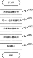
<形状情報取得処理>次に、図3を参照して、実施形態1の形状情報取得処理について説明する。 <Shape Information Acquisition Process> Next, the shape information acquisition process of the first embodiment will be described with reference to FIG.
なお、図3の処理は、制御部108が内蔵メモリ107に格納されているプログラムを実行し各部を制御することにより実現される。後述する図5、図6および図8でも同様である。
The processing of FIG. 3 is realized by the
S301「照度差画像取得」では、複数の照明部110を個別に点灯させることで、被写体に対して異なる方向から照明し、各方向から照明した被写体を撮影することで照度差画像を取得する。具体的には、異なる位置にある少なくとも3つ以上の照明部110からの光を順次照射し、撮影装置103で被写体を撮像し、撮影画像を内蔵メモリ107に記録する。各照明部110より照明した状態で撮影するために、制御部108は照明部110と撮影装置103の動作およびタイミングの制御を行う。
In S301 “Acquisition of illuminance difference image”, the plurality of
S302「パターン投影画像取得」では、撮影装置103により被写体へパターン光を投影した状態で撮影することでパターン投影画像を取得する。投影部111でパターン光109を生成し、被写体に照射する。この状態で撮影し、パターン投影画像を取得し、内蔵メモリ107に蓄える。このようなパターン光投影を行った状態で撮影するために、制御部108は投影部111と撮影装置103の動作およびタイミングの制御を行う。
In S302 “Pattern projection image acquisition”, the pattern projection image is acquired by shooting with the
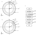
S303「投影部位置検出」では、演算処理部106は、パターン投影画像を用いて投影部111の位置を検出する。パターン投影画像におけるラインパターンの方向は、投影部111の円周上の位置に応じて変化する。図4は照明装置101の設置例とパターン投影画像142の例を示している。図4(a)、(b)、(c)は、それぞれ投影部111が0度方向、45度方向、90度方向の位置にあるときの照明装置101と、各位置からパターンを平面に投影した際の投影画像142を表している。投影部が各位置にあるとき、投影画像142のラインパターンはそれぞれ縦方向、斜め45度方向、水平方向に延びるパターンとなる。これを利用し、投影画像142におけるラインパターンの方向を検出し、投影部111の位置を検出する。初めに、パターン投影画像に含まれるエッジを検出する。エッジの検出方法は既知の方法を用いることができる。例えばパターン投影画像に対してソーベルフィルタなどの微分フィルタを施すことで、水平方向および垂直方向の微分画像を生成し、微分値が所定値より大きい領域をエッジとして検出する。次に水平成分の微分画像と垂直成分の微分画像の比を算出することでエッジの方向を検出する。パターンの方向と投影部の位置との関係に関する情報を予め保持しておき、検出したパターンの方向と照合することで投影部111の位置を検出する。
In S303 “projection unit position detection”, the
S304「照明部位置検出」では、演算処理部106は、S303で求めた投影部111の位置情報に基づき照明部110の位置を検出する。投影部111および照明部110の基準位置情報は予め記録されており、検出した投影部111の位置と基準位置(本実施形態では真上の位置)との差から移動量を算出し、照明部110の基準位置に、算出した移動量を加算することで、各照明部110の位置を算出することができる。
In S304 "illumination unit position detection", the
S305「形状算出」では、演算処理部106は、前述の既知の方法により形状情報を算出する。S304で求めた各照明部110の位置情報から照度差画像の各画像を撮影した際の照明方向を求めることができる。照度差画像の各照明方向と輝度値より、形状情報である面法線情報を算出することができる。
In S305 “shape calculation”, the
上述した形状情報取得処理により、照明装置が基準取り付け位置からずれた異なる位置に取り付けられている場合であっても各照明部の位置情報を取得することができ、高精度な形状情報を取得することができる。 By the shape information acquisition process described above, it is possible to acquire the position information of each illuminating unit even when the lighting device is mounted at different positions deviated from the reference mounting position, and acquire the highly accurate shape information. be able to.
(パターン方向の検出方法)
S303「投影部位置検出」において、パターン投影画像内でエッジの方向の変化量が所定の閾値より小さい領域、すなわちエッジの直線性が所定の誤差範囲内の領域(直線性が高い領域)を抽出し、この領域の画像を用いてパターンの方向検出を行ってもよい。例えば、前述の方法で水平成分の微分画像と垂直成分の微分画像を算出し、両者の比をとることでエッジの方向の分布を表すエッジ方向画像を生成する。エッジ方向画像のうち値が一様な領域を選出することで、直線性が高い領域を検出することができる。異なる距離にある物体の境界や凹凸がある物体にパターン光を投影すると、距離の変化によってパターン光の形状が歪むため、正しく方向検出ができなくなる。このような方法を用いることで、撮影領域内の被写体領域の中から距離の変化量が所定の閾値より小さい領域でパターンの方向検出を行うことができ、高精度な方向検出および投影部の位置検出が可能となる。
(Pattern direction detection method)
In S303 "projection position detection", an area in which the amount of change in the direction of the edge is smaller than a predetermined threshold value in the pattern projection image, that is, an area in which the linearity of the edge is within a predetermined error range (area with high linearity) However, the direction of the pattern may be detected using the image of this area. For example, the differential image of the horizontal component and the differential image of the vertical component are calculated by the above-described method, and the ratio of the two is calculated to generate the edge direction image representing the distribution in the edge direction. By selecting a region having a uniform value in the edge direction image, a region having high linearity can be detected. When pattern light is projected on an object having boundaries or irregularities of objects at different distances, the shape of the pattern light is distorted due to the change in the distance, and the direction cannot be detected correctly. By using such a method, it is possible to detect the direction of the pattern in an area in which the amount of change in distance is smaller than a predetermined threshold value from within the subject area within the shooting area, and to detect the direction and position of the projection unit with high accuracy. It becomes possible to detect.
また、投影部111の位置検出において、パターン投影がない画像を取得し、パターン投影画像との差もしくは比を取ることで、パターン強調画像を生成し、使用してもよい。パターン投影がない画像は、例えば投影部111を消灯して撮影することで取得できる。あるいは照度差画像の一部の画像もしくは全画像の平均画像を用いてもよい。パターンの方向検出を行う際に、被写体に模様があると、投影パターンのエッジの方向の他に複数のエッジの方向が検出され、検出誤差となる。このようなパターン強調画像を用いると、被写体がもつテクスチャの影響を低減することができ、パターン投影画像のパターンの方向をより高精度に検出することができ、投影部の高精度な位置検出が可能となる。
Further, in detecting the position of the
S303「投影部位置検出」において、微分フィルタを用いた方法について述べたが、他の方法を用いてもよい。例えば画像をハフ変換し、直線検出と直線の方向を求めてもよい。あるいは、既知のパターンマッチングを用いてもよい。予め基準画像を用意しておく。基準画像は、平面にパターンを投影して撮影した画像や投影部を構成するマスクパターンの透過率分布を画像に変換したものを使用することができる。あるいは投影部のLCOS(Liquid Crystal On Silicon)やDMD(Digital Micromirror Device)などを使用する場合は、パターン投影で使用する元画像等を使用することができる。基準画像と取得したパターン投影画像とを相対的に回転させて相関値を算出し、相関が最も高い回転方向をパターンの方向として検出することができる。このような方法を用いることで、投影パターンはラインパターンに限定されず、任意のパターンを用いることができる。 Although the method using the differential filter is described in S303 “Projection Position Detection”, other methods may be used. For example, the image may be Hough-transformed to detect the straight line and determine the direction of the straight line. Alternatively, known pattern matching may be used. A reference image is prepared in advance. As the reference image, an image obtained by projecting a pattern on a plane and an image obtained by converting the transmittance distribution of a mask pattern forming the projection unit into an image can be used. Alternatively, when LCOS (Liquid Crystal On Silicon) or DMD (Digital Micromirror Device) of the projection unit is used, the original image or the like used in the pattern projection can be used. The correlation value is calculated by relatively rotating the reference image and the acquired pattern projection image, and the rotation direction having the highest correlation can be detected as the pattern direction. By using such a method, the projection pattern is not limited to the line pattern, and any pattern can be used.
(距離情報を用いた投影部の位置検出方法)
S303の「投影部位置検出」において、距離情報を用いることで、より高精度に投影部の位置を検出することができる。図5は距離情報を用いた形状情報取得処理を示している。
(Method of detecting position of projection unit using distance information)
By using the distance information in the “projection unit position detection” in S303, the position of the projection unit can be detected with higher accuracy. FIG. 5 shows a shape information acquisition process using distance information.
S301「照度差画像取得」は図3のS301と同様である。 S301 "Illuminance difference image acquisition" is the same as S301 of FIG.
S302「パターン投影画像取得」では、図3のS302と同様にパターン投影画像を取得する。被写体へパターン光を投影した状態で撮影することで視差を有するパターン投影画像であるA画像とB画像からなる画像対を取得し、内蔵メモリ107に保存する。被写体102の模様(テクスチャともいう)が乏しいとき、投影部111からのパターン光投影を併用しないで周辺環境光のみで撮影をした場合にはA画像やB画像のコントラストやS/N比が低下し、相関演算による距離演算精度が低下する。このため、投影部111からパターン光の投影を行い、被写体102の表面にテクスチャを重畳した状態で撮影を行うことで距離演算精度を向上させる。
In S302 “Pattern projection image acquisition”, a pattern projection image is acquired as in S302 of FIG. An image pair consisting of the A image and the B image, which are pattern projection images having parallax, is acquired by shooting with the pattern light projected onto the subject, and the image pair is stored in the
S307「距離算出」では、演算処理部106は、S302で取得したパターン投影画像を用いて被写体の距離情報を算出する。
In S307 “distance calculation”, the
ここで、図5(b)を用いて、基準画像および参照画像の位置関係を説明する。符号310AはA画像、符号310BはB画像を表している。初めに、A画像とB画像の相関値を算出する。A画像において距離演算処理を行う画素320(注目画素と呼ぶ)とその近傍画素を含む部分領域を抜き出し基準画像311とする。次に、B画像で基準画像と同面積の領域を抜き出して参照画像313とする。B画像で参照画像を抜き出す位置を瞳分割方向と同じx軸方向に移動させ、各移動量における参照画像と基準画像との相関値を算出することで、各移動量に対する相関値のデータ列からなる相関値を算出する。参照画像を移動させて相関演算を行う方向を視差算出方向と呼ぶ。視差算出方向は瞳分割方向と同じ方向に設定することでA画像とB画像の被写体距離に応じて生じる視差量を正しく算出することができる。相関値の算出は、SAD(Sum of Absolute Difference)やSSD(Sum of Squared Difference)などの一般的な算出方法を用いることができる。
Here, the positional relationship between the standard image and the reference image will be described with reference to FIG.
次に、求めた相関値より視差量を算出する。視差量は、既存の方法を用いて算出することができる。例えば、相関値の中で最も高い相関が得られる移動量とその近傍の移動量に対応する相関値のデータ列を抽出し、既知の内挿方法により、最も相関が高くなる移動量をサブピクセル精度で推定することで、視差量を算出することができる。 Next, the amount of parallax is calculated from the obtained correlation value. The parallax amount can be calculated using an existing method. For example, the data amount of the correlation value corresponding to the movement amount having the highest correlation among the correlation values and the movement amount in the vicinity thereof is extracted, and the movement amount having the highest correlation is determined by the known interpolating method. The amount of parallax can be calculated by estimating with accuracy.
算出した視差量は、既知の方法によりデフォーカス量または被写体距離に変換することができる。視差量からデフォーカス量への換算は、基線長を用いた幾何学的関係から算出することができる。また、デフォーカス量から被写体距離への変換は、結像光学系104の結像関係を用いて行えばよい。あるいは視差量に所定の変換係数を乗算することでデフォーカス量または被写体距離に変換してもよい。このような方法により、注目画素における距離情報を算出することができ、各画素で上述した演算を行うことで視差画像あるいはデフォーカス画像あるいは距離画像を求めることができる。
The calculated parallax amount can be converted into a defocus amount or a subject distance by a known method. The conversion from the parallax amount to the defocus amount can be calculated from the geometrical relationship using the base line length. Further, the conversion from the defocus amount to the subject distance may be performed using the image forming relationship of the image forming
S308「評価領域決定」では、演算処理部106は、パターン投影画像内において投影部111の位置検出を行う評価領域を決定する。初めに、距離画像内の部分領域毎に標準偏差を算出する。次に、部分領域のうち、標準偏差が所定の基準値より小さい領域を評価領域として選出する。これにより距離の変化量が所定の閾値より小さい領域を評価領域として決定することができる。
In S308 “Evaluation Area Determination”, the
S303「投影部位置検出」では、図3のS303と同様にパターン投影画像を用いて投影部の位置を検出する際に、S308で決定した評価領域の画像を用いて投影部111の位置検出を行う。
In S303 “projection unit position detection”, when the position of the projection unit is detected using the pattern projection image as in S303 of FIG. 3, the position of the
S304「照明部位置検出」およびS305「形状算出」では、図3と同様に照明部110の位置を検出し、形状情報を算出する。
In S304 "illumination unit position detection" and S305 "shape calculation", the position of the
異なる距離にある物体の境界や凹凸がある物体にパターン光を投影すると、距離の変化によってパターン光の形状が歪むため、正しく方向検出ができなくなる。距離情報を使用し、距離の変化量が所定の閾値より小さい領域の画像を用いて、投影部の位置検出を行うことで、撮影領域内に異なる距離にある複数の物体や凹凸が大きい物体が撮影領域内に存在する場合でも、パターン投影画像の方向検出を高精度に行うことができる。 When pattern light is projected on an object having boundaries or irregularities of objects at different distances, the shape of the pattern light is distorted due to the change in the distance, and the direction cannot be detected correctly. By using the distance information and detecting the position of the projection unit by using the image of the area in which the amount of change in the distance is smaller than the predetermined threshold value, multiple objects at different distances or objects with large unevenness can be detected in the shooting area. Even if the pattern projection image exists in the shooting area, the direction of the pattern projection image can be detected with high accuracy.
上述した形状情報取得処理により、照明装置101が基準取り付け位置からずれた位置に設置されている場合でも、各照明部110の位置を高精度に検出することができ、より高精度な形状情報を取得することができる。
By the shape information acquisition process described above, even if the
なお、実施形態1では距離画像を用いて評価領域を決定する方法について述べたが、距離画像の代わりに視差画像やデフォーカス画像を用いてもよい。視差量およびデフォーカス量は距離に応じて変化するため、視差画像およびデフォーカス画像を用い、距離変動が小さい領域を検出し、評価領域として決定してもよい。同等の効果を得ることができる。 In the first embodiment, the method of determining the evaluation area using the distance image has been described, but a parallax image or a defocus image may be used instead of the distance image. Since the parallax amount and the defocus amount change according to the distance, the parallax image and the defocus image may be used to detect a region in which the distance variation is small and determine the region as the evaluation region. The same effect can be obtained.
(影情報を用いた形状算出方法)
照度差画像を用いて影の領域を検出し、物体の相対的な距離関係を表す相対距離情報や距離が大きく変化する領域を表す境界情報などの形状情報を取得してもよい。距離差がある物体を照明すると、手前にある物体に遮られて、照明が当たらない影領域が発生する。この領域は、撮影画像では所定輝度値以下の低輝度の領域となる。一方向の照明で取得した画像では、被写体反射率が低いために低輝度の領域との判別ができない。
(Shape calculation method using shadow information)
The shadow area may be detected using the illuminance difference image, and shape information such as relative distance information indicating a relative distance relationship between objects and boundary information indicating an area in which the distance greatly changes may be acquired. When an object with a difference in distance is illuminated, it is blocked by an object in the foreground and a shadow area where the illumination is not generated occurs. This region is a low-luminance region having a predetermined luminance value or less in the captured image. An image obtained by unidirectional illumination cannot be distinguished as a low-luminance region because the subject reflectance is low.
そこで、複数の方向から照明を行って取得した照度差画像を用い、方向の変化による輝度値の変化量が所定の閾値より大きい画素領域を影領域として検出する。これにより低輝度の領域と影領域とを分離して検出することができる。検出した影領域と照明方向から、撮影装置103に対して手前の物体領域と奥側の領域とを検出することができ、相対距離情報を得ることができる。また、影領域と手前の物体領域との境界領域を検出することができ、境界情報を得ることができる。前述した方法で、照明方向を検出することで、より高精度にこれらの形状情報を取得することができる。本実施形態における形状情報とは、被写体の法線情報や所定の基準位置からの絶対距離情報あるいは被写体領域内の相対距離情報である。
Therefore, by using the illuminance difference images obtained by illuminating from a plurality of directions, a pixel area in which the change amount of the brightness value due to the change in the direction is larger than a predetermined threshold value is detected as a shadow area. This makes it possible to detect the low-luminance region and the shadow region separately. From the detected shadow area and illumination direction, the object area in front of and the area on the back side of the
(照明部が1つの構成)
本実施形態では照明装置101を複数の照明部110で構成した例を示したが単一の照明部で構成してもよい。図6は、照明装置101を単一の照明部118で構成する例を示している。
(A single lighting unit)
In the present embodiment, an example in which the
照明部118は固定部112の所定の位置に配置されている。照明装置101は図6(a)、(b)に示すように、照明部110および投影部111は撮影装置103の光軸140を中心に手動または自動で回転可能に構成されている。照明部110と投影部111の位置関係は図6(a)、(b)のように結像光学系104の光軸140に垂直な平面において、光軸140から等距離にある1つの円周141上にある位置関係となっている。
The illumination unit 118 is arranged at a predetermined position on the fixed
図6(c)は照明装置101を単一の照明部で構成した場合の形状情報取得処理を示している。
FIG. 6C shows the shape information acquisition process when the
S331「照度差画像取得」では、制御部108は照明部110と撮影装置103を制御して、照明装置101により任意の位置にある状態で照明と撮影を行って画像を取得する。ここでは、照明装置101の位置を回転させることで照明部118の位置を変更しながら照明と撮影を行う。必要に応じて照明部の位置の変更と照明と撮影を複数回行うことで照度差画像を取得する。
In S331 “Illuminance difference image acquisition”, the
S332「パターン投影画像取得」では、制御部108は投影部111と撮影装置103を制御して、被写体にパターン光を投影した状態で撮影することでパターン投影画像を取得する。ここでは、S331で照明装置101を回転させながら照度差画像を取得すると共に、照明部110の各回転位置において、投影部111でパターン光を投影し、投影画像を取得する。
In S332 "acquisition of pattern projection image", the
S333「投影部位置検出」では、演算処理部106は、照明部110の各回転位置におけるパターン投影画像を用いて各回転位置における投影部の位置を検出する。投影部111の位置検出方法は図3や図5で説明したいずれかの方法を用いることができる。
In S333 “projection unit position detection”, the
S334「照明部位置検出」では、演算処理部106は、照明部110の各回転位置で検出した投影部111の位置と基準位置情報とに基づいて各回転位置における照明部110の位置を算出する。各回転位置における照明部110の位置検出方法は図3や図5で説明した方法と同様である。
In S334 “illumination unit position detection”, the
S305「形状算出」では、演算処理部106は、図3や図5で説明した方法で形状情報を算出する。
In S305 “shape calculation”, the
以上の形状情報取得処理によれば、照明装置101が基準取り付け位置からずれた位置にある場合でも照明部110の各回転位置の情報を取得することができ、高精度な形状情報を取得することができる。また、照明部110の数を減らすことができるので、照明装置101の部品点数を削減することができ、より安価に装置を構成することができる。
According to the above-described shape information acquisition processing, it is possible to acquire information on each rotation position of the
[実施形態2]次に、実施形態2について説明する。 [Second Embodiment] Next, a second embodiment will be described.
<装置構成>まず、図7を参照して、実施形態2の形状情報取得装置の構成および機能について説明する。 <Device Configuration> First, the configuration and function of the shape information acquisition device according to the second embodiment will be described with reference to FIG. 7.
実施形態2の形状情報取得装置200において、撮影装置103は、結像光学系104、撮像素子105、演算処理部106、内蔵メモリ107を備える。また、偏光制御装置401と撮影装置103は制御部108に接続され同期などの制御を受ける。
In the shape
偏光制御装置401は、偏光素子411と、投影部111と、偏光素子411および投影部111を撮影装置103に取り付けるための固定部412と、を備える。偏光素子411と投影部111は、撮影装置103の結像光学系104の光軸140に垂直な平面に配置される。図7(b)において413は結像光学系104の外形を示している。
The polarization control device 401 includes a polarization element 411, a
偏光素子411は、その偏光軸または透過軸に平行な光を透過し、他の振動方向の光の透過を阻止する素子であり、透過軸の方向が可変な素子である。偏光素子411は、例えば、1/4波長位相板とVA(Vertical Alignment)タイプの液晶素子と偏光板を備える。1/4波長位相板と偏光板は、1/4波長位相板の遅相軸または進相軸が偏光板の透過軸と平行になるように配置される。偏光制御装置401は図示しない駆動部を備えており、液晶素子に電圧を印加する。駆動部により、印加電圧を変化させることで、液晶分子の配向方向が変化し、偏光素子411の透過軸の方向を変更することができる。図7(c)、(d)、(e)は透過軸の方向を示したもので、印加電圧を増加または低下させると図示のように偏光素子を透過する透過軸414の方向が変化する。 The polarization element 411 is an element that transmits light parallel to its polarization axis or transmission axis and blocks transmission of light in other vibration directions, and has a variable transmission axis direction. The polarizing element 411 includes, for example, a ¼ wavelength phase plate, a VA (Vertical Alignment) type liquid crystal element, and a polarizing plate. The 1/4 wavelength phase plate and the polarizing plate are arranged such that the slow axis or the fast axis of the 1/4 wavelength phase plate is parallel to the transmission axis of the polarizing plate. The polarization control device 401 includes a drive unit (not shown) and applies a voltage to the liquid crystal element. By changing the applied voltage by the driving unit, the alignment direction of the liquid crystal molecules is changed, and the direction of the transmission axis of the polarizing element 411 can be changed. 7C, 7D, and 7E show the directions of the transmission axes, and when the applied voltage is increased or decreased, the directions of the transmission axes 414 that pass through the polarization element change as shown in the drawing.
固定部412は、偏光素子411と投影部111を撮影装置103または三脚などの撮影補助機材(不図示)に固定する部材である。偏光素子411と照明装置は、固定部412に対して着脱可能に構成してもよい。また固定部412は撮影装置103または撮影補助機材に対して着脱可能に構成してもよい。所定の電圧を印加したときの偏光素子411の透過軸方向と、投影部の位置情報とが既知であり、このときの電圧を基準電圧、方向を基準方向、位置を基準位置と呼ぶ。また、偏光制御装置401の取り付け位置を基準取り付け位置と呼ぶ。これらの基準電圧、基準方向および基準位置の各基準情報は内蔵メモリ107あるいは偏光制御装置401の内部に設けたメモリに記録されている。
The fixing unit 412 is a member that fixes the polarizing element 411 and the
<形状情報取得処理>
次に、図8を参照して、実施形態2の形状情報取得処理について説明する。
<Shape information acquisition process>
Next, the shape information acquisition process of the second embodiment will be described with reference to FIG.
S501「偏光画像取得」では、制御部108は偏光制御装置401および撮影装置103を制御して、所定の透過軸として被写体像光を撮影することで偏光画像を取得する。このとき不図示の駆動部により所定の電圧を偏光素子411に印加することで、透過軸の方向を設定し、撮影を行う。次に印加電圧を変更し、他の透過軸での撮影を行う。異なる透過軸で被写体像光を撮影することで、複数の偏光画像を取得できる。偏光画像は内蔵メモリ107に保存される。
In S501 “polarized image acquisition”, the
S302「パターン投影画像取得」およびS303「投影部位置検出」では、図3と同様に、パターン投影画像の取得と投影部111の位置検出を行う。
In S302 “Pattern projection image acquisition” and S303 “Projection unit position detection”, the pattern projection image is acquired and the position of the
S504「透過軸の方向検出」では、演算処理部106は、S303で求めた投影部111の位置情報に基づいて偏光素子411に印加した電圧ごとに偏光素子411の透過軸の方向を検出する。基準電圧における透過軸の基準方向と投影部111の基準位置は既知であるため、投影部111の位置と基準位置の差、印加電圧と基準電圧の差から透過軸の基準方向との差を求めることができる。
In S504 “transmission axis direction detection”, the
S505「形状情報算出」では、演算処理部106は、既知の方法により形状情報を算出する。S501で取得した偏光画像と、S504で検出した透過軸の方向情報とに基づいて、既知の方法で形状情報である面法線情報を算出することができる。物体に非偏光の光が入射すると、物体の面法線に応じて反射光に含まれるS偏光とP偏光の割合が変化する。取得した偏光画像からS偏光とP偏光の割合を分析することで、被写体の面法線情報を算出することができる。
In S505 "shape information calculation", the
上述した形状情報取得処理によれば、偏光制御装置401が基準取り付け位置からずれた位置に設置されている場合でも、偏光素子411の透過軸の方向を検出することができ、高精度な形状情報を取得することができる。 According to the shape information acquisition process described above, even when the polarization control device 401 is installed at a position displaced from the reference mounting position, the direction of the transmission axis of the polarization element 411 can be detected, and highly accurate shape information can be obtained. Can be obtained.
なお、本実施形態ではVA液相素子を用いて偏光素子411を構成する例を示したが、他の位相板や液晶素子を用いて構成してもよい。 In the present embodiment, the example in which the polarization element 411 is configured by using the VA liquid phase element is shown, but it may be configured by using another phase plate or liquid crystal element.
また、液晶素子に電圧を印加することで偏光素子411を透過する光の透過状態を変更する例について示したが、偏光素子411または液晶素子を機械的に回転するように構成してもよい。このとき偏光素子411または液晶素子を自動あるいは手動で回転させてもよい。前述と同様に偏光制御装置401が基準取り付け位置から異なる位置に設定されている場合でも、偏光素子411の透過軸の方向を検出することができ、高精度な形状情報を取得することができる。 Further, although an example in which the transmission state of light passing through the polarization element 411 is changed by applying a voltage to the liquid crystal element has been shown, the polarization element 411 or the liquid crystal element may be mechanically rotated. At this time, the polarizing element 411 or the liquid crystal element may be automatically or manually rotated. Similar to the above, even when the polarization control device 401 is set at a position different from the reference mounting position, the direction of the transmission axis of the polarization element 411 can be detected, and highly accurate shape information can be acquired.
[実施形態3]次に、実施形態3について説明する。 [Third Embodiment] Next, a third embodiment will be described.
実施形態1では撮影装置103で被写体の形状情報を算出したが、実施形態3では撮影装置103とは別に設けられた画像処理装置600を用いて被写体の形状情報を算出する。
In the first embodiment, the photographing
以下、図9を参照して、実施形態3の画像処理装置の構成および機能について説明する。 The configuration and function of the image processing apparatus according to the third embodiment will be described below with reference to FIG.
実施形態3の画像処理装置600は、例えばパーソナルコンピュータ(PC)などの情報処理装置である。画像処理装置600は撮影装置103と有線または無線により通信可能に接続され、撮影装置103で取得した照度差画像とパターン投影画像のデータを受信可能である。画像処理装置600は、図3のS303〜S305の処理を行う演算処理部を有している。S301とS302で取得した照度差画像データおよびパターン投影画像データが有線また無線で画像処理装置600に送信され、演算処理部において処理が実施されることで形状情報を取得することができる。このような構成であっても実施形態1と同様に、投影部および照明部の位置を高精度に検出でき、高精度な形状情報を取得することができる。
The
なお、投影部および照明部の基準位置情報は、照度差画像またはパターン投影画像の付加情報として画像データと共に記録してもよい。あるいは図3のS304の処理を撮影装置103の演算処理部106で行い、求めた各照明部の位置情報を照度差画像またはパターン投影画像の付加情報として画像データと共に記録してもよい。これらの基準位置情報は予め画像処理装置600の内部の記憶装置に格納しておいてもよい。あるいは、これらの基準位置情報あるいは各照明部の位置情報はインターネットで接続された他の記憶装置に格納しておき、形状情報を算出するときに他の記憶装置からデータを読み出して使用してもよい。画像処理装置600の演算処理部で形状算出を行うときに、画像データと位置情報を用いて形状情報を算出することができる。
The reference position information of the projection unit and the illumination unit may be recorded together with the image data as additional information of the illuminance difference image or the pattern projection image. Alternatively, the processing of S304 of FIG. 3 may be performed by the
[他の実施形態]
偏光制御装置401は撮影装置103に備えられた演算処理部106で構成することも、装置小型化の観点から好適である。
[Other Embodiments]
It is also preferable to configure the polarization control device 401 by the
投影部111は、光源としてLD(Laser Diode)を用いてもよい。反射型LCOSや透過型LCOSやDMDを用いてもよい。被写体の大きさや距離に応じて投影パターンの周期を適時変えることができ、状況に応じてより高精度な測距が可能となる。投影部111の光源の波長が可視光域の全域を含む白色であることは、本実施形態にて被写体の分光反射率によらず反射率補正の効果が得られるため好適である。投影部111の光源がR、G、Bの3色から構成されていることは撮影装置103のカラーフィルタ透過帯域と一致し、使用エネルギーに対する光利用効率の観点で好適である。投影部111の光源が赤外(IR)領域であり、これに対応した透過帯域ならびに受光感度を持つカラーフィルタならびに撮像素子を備えた撮像装置を用いて撮影を行うことは、RGB帯域を用いた鑑賞用画像を同時に撮影することが可能になり好適である。特にIRの波長帯域が800nmから1100nmの間である場合、光電変換部にSiを用いることができ、カラーフィルタの配列を変更することで1つの撮像素子でRGB鑑賞画像とIR測距画像を取得することができ好適である。
The
撮影装置103は、2つ以上の複数の光学系と各光学系に対応する撮像素子を備えるステレオカメラで構成してもよい。これは基線長の設計自由度が向上し、測距分解能が向上する観点から好適である。また、照明装置101または偏光制御401と撮影装置103とを分離して構成してもよい。
The
また、本発明は、上述の実施形態の1以上の機能を実現するプログラムを、ネットワークまたは記憶媒体を介してシステムまたは装置に供給し、そのシステムまたは装置のコンピュータにおける1つ以上のプロセッサがプログラムを読出し実行する処理でも実現可能である。また、1以上の機能を実現する回路(例えば、ASIC)によっても実現可能である。 The present invention also supplies a program that implements one or more functions of the above-described embodiments to a system or apparatus via a network or a storage medium, and one or more processors in a computer of the system or apparatus execute the program. It can also be realized by a process of reading and executing. It can also be realized by a circuit (for example, ASIC) that realizes one or more functions.
100…形状情報取得装置、101…照明装置、102…被写体、103…撮影装置、104…結像光学系、105…撮像素子、106…演算処理部、107…内蔵メモリ
Claims (25)
前記パターン投影画像に基づいて前記照明部の位置を検出する検出手段と、
前記照度差画像と前記照明部の位置とに基づいて前記被写体の形状情報を算出する形状算出手段と、を有することを特徴とする形状情報取得装置。 An acquisition unit that acquires an illumination difference image obtained by illuminating the subject from different directions by the illumination unit and a pattern projection image obtained by projecting predetermined pattern light onto the subject by the projection unit,
A detection unit that detects the position of the illumination unit based on the pattern projection image;
A shape information acquisition device comprising: a shape calculation unit that calculates shape information of the subject based on the illuminance difference image and the position of the illumination unit.
前記検出手段は、前記パターン投影画像に基づいて前記投影部の位置を検出し、前記投影部の位置と前記基準位置情報とに基づいて前記照明部の位置を検出することを特徴とする請求項3から5のいずれか1項に記載の形状情報取得装置。 Further comprising a holding unit that holds the position of the projection unit and the position of the illumination unit when the illumination unit is attached to a predetermined position as reference position information,
The detection unit detects the position of the projection unit based on the pattern projection image, and detects the position of the illumination unit based on the position of the projection unit and the reference position information. The shape information acquisition device according to any one of 3 to 5.
前記撮影手段は、前記複数の光源を個別に点灯させた状態で撮影することで前記照度差画像を取得し、
前記検出手段は、前記複数の光源の位置を前記照明部の位置として検出することを特徴とする請求項2から6のいずれか1項に記載の形状情報取得装置。 The lighting unit includes a plurality of light sources arranged at different positions,
The photographing means acquires the illuminance difference image by photographing in a state where the plurality of light sources are individually turned on,
The shape information acquisition apparatus according to claim 2, wherein the detection unit detects positions of the plurality of light sources as positions of the illumination unit.
前記撮影手段は、前記光源の位置を変更して撮影することで前記照度差画像を取得することを特徴とする請求項2から6のいずれか1項に記載の形状情報取得装置。 The illumination unit is provided with a single light source rotatable about the optical axis of the photographing means,
The shape information acquisition apparatus according to claim 2, wherein the imaging unit acquires the illuminance difference image by changing the position of the light source and imaging.
前記検出手段は、前記視差画像の相関演算により前記距離情報を算出することを特徴とする請求項13に記載の形状情報取得装置。 The acquisition means acquires a parallax image based on a light flux that has passed through different pupil regions of the optical system,
The shape information acquisition apparatus according to claim 13, wherein the detection unit calculates the distance information by performing a correlation calculation of the parallax images.
前記パターン投影画像に基づいて前記透過する方向を検出する検出手段と、
前記偏光画像と前記透過する方向とに基づいて前記被写体の形状情報を算出する形状算出手段と、を有することを特徴とする形状情報取得装置。 An acquisition unit that acquires a polarized image having different directions of transmission through the polarizing element and a pattern projection image obtained by projecting predetermined pattern light on the subject by the projection unit,
Detecting means for detecting the transmitting direction based on the pattern projection image;
A shape information acquisition device comprising: a shape calculation unit that calculates shape information of the subject based on the polarized image and the transmission direction.
前記偏光制御手段は、前記偏光素子および前記投影部を前記撮影手段に取り付けるための固定部を有することを特徴とする請求項19に記載の形状情報取得装置。 The polarizing element and the projection unit are arranged on a plane perpendicular to the optical axis of the optical system of the photographing means,
20. The shape information acquisition device according to claim 19, wherein the polarization control unit has a fixing unit for mounting the polarization element and the projection unit to the imaging unit.
前記検出手段は、前記パターン投影画像に基づいて前記投影部の位置を検出し、前記投影部の位置と前記基準情報とに基づいて前記透過する方向を検出することを特徴とする請求項19または20に記載の形状情報取得装置。 Further comprising holding means for holding, as reference information, the position of the projection unit and the transmission direction of the polarizing element when the polarization control means is attached at a predetermined position,
20. The detecting unit detects the position of the projection unit based on the pattern projection image, and detects the transmission direction based on the position of the projection unit and the reference information. The shape information acquisition device according to item 20.
検出手段が、前記パターン投影画像に基づいて前記照明部の位置を検出するステップと、
形状算出手段が、前記照度差画像と前記照明部の位置とに基づいて前記被写体の形状情報を算出するステップと、を有することを特徴とする形状情報取得方法。 A shape information acquisition method in a device capable of acquiring an illumination difference image in which a subject is illuminated from different directions by an illumination unit and a pattern projection image in which a predetermined pattern light is projected on the subject by a projection unit,
A step of detecting a position of the illumination unit based on the pattern projection image,
The shape calculation means includes a step of calculating shape information of the subject based on the illuminance difference image and the position of the illumination unit.
検出手段が、前記パターン投影画像に基づいて前記透過する方向を検出するステップと、
形状算出手段が、前記偏光画像と前記透過する方向とに基づいて前記被写体の形状情報を算出するステップと、を有することを特徴とする形状情報取得方法。 A shape information acquisition method in a device capable of acquiring a polarized image having different directions of light transmitted through a polarizing element and a pattern projection image obtained by projecting predetermined pattern light on a subject by a projection unit,
A step in which the detecting means detects the transmitting direction based on the pattern projection image;
The shape calculation means calculates the shape information of the subject based on the polarization image and the transmission direction, and the shape information acquisition method.
Priority Applications (2)
| Application Number | Priority Date | Filing Date | Title |
|---|---|---|---|
| JP2018231940A JP7236854B2 (en) | 2018-12-11 | 2018-12-11 | Shape information acquisition device, shape information acquisition method, program, and storage medium |
| US16/701,998 US11176695B2 (en) | 2018-12-11 | 2019-12-03 | Shape information acquisition apparatus and shape information acquisition method |
Applications Claiming Priority (1)
| Application Number | Priority Date | Filing Date | Title |
|---|---|---|---|
| JP2018231940A JP7236854B2 (en) | 2018-12-11 | 2018-12-11 | Shape information acquisition device, shape information acquisition method, program, and storage medium |
Publications (2)
| Publication Number | Publication Date |
|---|---|
| JP2020094876A true JP2020094876A (en) | 2020-06-18 |
| JP7236854B2 JP7236854B2 (en) | 2023-03-10 |
Family
ID=70972746
Family Applications (1)
| Application Number | Title | Priority Date | Filing Date |
|---|---|---|---|
| JP2018231940A Active JP7236854B2 (en) | 2018-12-11 | 2018-12-11 | Shape information acquisition device, shape information acquisition method, program, and storage medium |
Country Status (2)
| Country | Link |
|---|---|
| US (1) | US11176695B2 (en) |
| JP (1) | JP7236854B2 (en) |
Citations (4)
| Publication number | Priority date | Publication date | Assignee | Title |
|---|---|---|---|---|
| JPH06274266A (en) * | 1993-03-23 | 1994-09-30 | Wacom Co Ltd | Optical position detector and optical coordinate input device |
| JP2016020891A (en) * | 2014-06-20 | 2016-02-04 | 株式会社リコー | Shape measurement system and imaging device |
| JP2017049179A (en) * | 2015-09-03 | 2017-03-09 | キヤノン株式会社 | Measurement device |
| JP2017072499A (en) * | 2015-10-08 | 2017-04-13 | キヤノン株式会社 | Processor, processing system, imaging apparatus, processing method, program, and recording medium |
Family Cites Families (4)
| Publication number | Priority date | Publication date | Assignee | Title |
|---|---|---|---|---|
| US20090109215A1 (en) * | 2007-10-31 | 2009-04-30 | Fein Gene S | Method and apparatus for user interface communication with an image manipulator |
| CN104412586B (en) * | 2012-04-25 | 2016-12-28 | 株式会社尼康 | Image processing apparatus, camera head |
| JPWO2016098400A1 (en) * | 2014-12-15 | 2017-09-21 | ソニー株式会社 | Imaging device assembly, three-dimensional shape measuring device, and motion detecting device |
| JP6274266B2 (en) | 2016-06-30 | 2018-02-07 | 株式会社寺岡精工 | Self-weighing device |
-
2018
- 2018-12-11 JP JP2018231940A patent/JP7236854B2/en active Active
-
2019
- 2019-12-03 US US16/701,998 patent/US11176695B2/en active Active
Patent Citations (4)
| Publication number | Priority date | Publication date | Assignee | Title |
|---|---|---|---|---|
| JPH06274266A (en) * | 1993-03-23 | 1994-09-30 | Wacom Co Ltd | Optical position detector and optical coordinate input device |
| JP2016020891A (en) * | 2014-06-20 | 2016-02-04 | 株式会社リコー | Shape measurement system and imaging device |
| JP2017049179A (en) * | 2015-09-03 | 2017-03-09 | キヤノン株式会社 | Measurement device |
| JP2017072499A (en) * | 2015-10-08 | 2017-04-13 | キヤノン株式会社 | Processor, processing system, imaging apparatus, processing method, program, and recording medium |
Also Published As
| Publication number | Publication date |
|---|---|
| US20200184665A1 (en) | 2020-06-11 |
| US11176695B2 (en) | 2021-11-16 |
| JP7236854B2 (en) | 2023-03-10 |
Similar Documents
| Publication | Publication Date | Title |
|---|---|---|
| US8199335B2 (en) | Three-dimensional shape measuring apparatus, three-dimensional shape measuring method, three-dimensional shape measuring program, and recording medium | |
| US10571668B2 (en) | Catadioptric projector systems, devices, and methods | |
| JP4787871B2 (en) | Color polarization imaging device | |
| US8025408B2 (en) | Method, apparatus and program for image processing and method and apparatus for image synthesizing | |
| KR100815283B1 (en) | System for simultaneous projections of multiple phase-shifted patterns for the three-dimensional inspection of an object | |
| US20050035314A1 (en) | Range finder and method | |
| EP3524929B1 (en) | Projection system | |
| KR20110084703A (en) | Board inspection apparatus | |
| JP2004132829A (en) | Method and apparatus for three-dimensional imaging, and stereo adapter | |
| JP2004239886A (en) | Three-dimensional image imaging apparatus and method | |
| TWI489079B (en) | Projection apparatus and depth measuring system | |
| JP6556013B2 (en) | PROCESSING DEVICE, PROCESSING SYSTEM, IMAGING DEVICE, PROCESSING METHOD, PROGRAM, AND RECORDING MEDIUM | |
| JP2006279546A (en) | Electronic camera, image processing program, and image processing method | |
| US10444162B2 (en) | Method of testing an object and apparatus for performing the same | |
| WO2017061213A1 (en) | Projection-type display device and image correction method | |
| JP2014060549A (en) | Illuminance output device, luminance output device and image projection device | |
| JP7118776B2 (en) | IMAGING DEVICE, IMAGE PROCESSING METHOD, IMAGE PROCESSING PROGRAM AND RECORDING MEDIUM | |
| JP7236854B2 (en) | Shape information acquisition device, shape information acquisition method, program, and storage medium | |
| JP2009236696A (en) | Three-dimensional image measurement method, measurement system, and measurement program for subject | |
| JP2021004762A (en) | Measurement device, imaging device, measurement system, control method, program and recording medium | |
| JP6432968B2 (en) | Object shape estimation apparatus and program | |
| JP2021127998A (en) | Distance information acquisition device and distance information acquisition method | |
| US11037316B2 (en) | Parallax calculation apparatus, parallax calculation method, and control program of parallax calculation apparatus | |
| TWI454831B (en) | Image-capturing system and method of capturing images by using the same | |
| JP2005106820A5 (en) |
Legal Events
| Date | Code | Title | Description |
|---|---|---|---|
| RD01 | Notification of change of attorney |
Free format text: JAPANESE INTERMEDIATE CODE: A7421 Effective date: 20210103 |
|
| A521 | Request for written amendment filed |
Free format text: JAPANESE INTERMEDIATE CODE: A523 Effective date: 20210113 |
|
| A621 | Written request for application examination |
Free format text: JAPANESE INTERMEDIATE CODE: A621 Effective date: 20211020 |
|
| A977 | Report on retrieval |
Free format text: JAPANESE INTERMEDIATE CODE: A971007 Effective date: 20220907 |
|
| A131 | Notification of reasons for refusal |
Free format text: JAPANESE INTERMEDIATE CODE: A131 Effective date: 20220916 |
|
| A521 | Request for written amendment filed |
Free format text: JAPANESE INTERMEDIATE CODE: A523 Effective date: 20221115 |
|
| TRDD | Decision of grant or rejection written | ||
| A01 | Written decision to grant a patent or to grant a registration (utility model) |
Free format text: JAPANESE INTERMEDIATE CODE: A01 Effective date: 20230130 |
|
| A61 | First payment of annual fees (during grant procedure) |
Free format text: JAPANESE INTERMEDIATE CODE: A61 Effective date: 20230228 |
|
| R151 | Written notification of patent or utility model registration |
Ref document number: 7236854 Country of ref document: JP Free format text: JAPANESE INTERMEDIATE CODE: R151 |